

Page 1
KKTTTT
KK
KKTTTT
KK
CCCC----222211112222PPPPWW
CCCC----222211112222SSSSHH
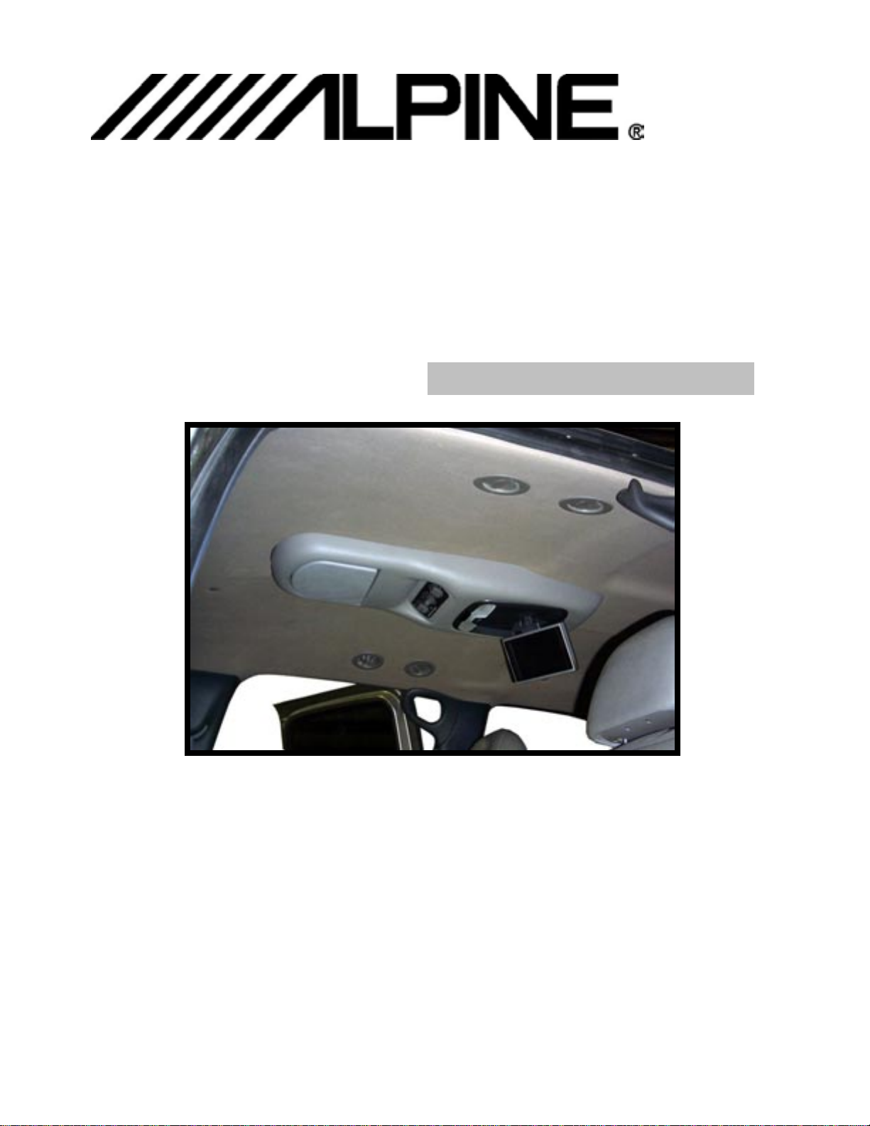
Overhead Console for use with Mobile Overhead Monitor
WW 55550000----0000333388886666
HH 55550000----0000333388886666
2000 TAHOE / YUKON
AAAA----0000111188
AAAA----0000222266
IIIINNNNSSSSTTTTAAAALLLLLLLLAAAATTTTIIIIOOOONNNN MMMMAAAANNNNUUUUAAAALLLL
88
66
These instructions are intended for use only by experienced professionals in the automotive
customizing business. Special tools and equipment, as well as specialized handling and care of
product during installation, may be required. Before beginning this installation, carefully read through
the following instructions. Use extreme care when cutting headliner material. Check for wiring
or other componentry above headliner material. Cut only where indicated.
Materials / Tools required for this installation:
1. Phillips screwdriver 2. Powered screwdriver or drill with adapter
3. Awl or scribe point tool or similar 4. Razor knife or similar tool
5. 18 GA wire 4' 6. Rubbing alcohol
7. ALPINE TMX-R680A Mobile Overhead Monitor
Jan. 1,2001
Printed in the U.S.A.
Page 2
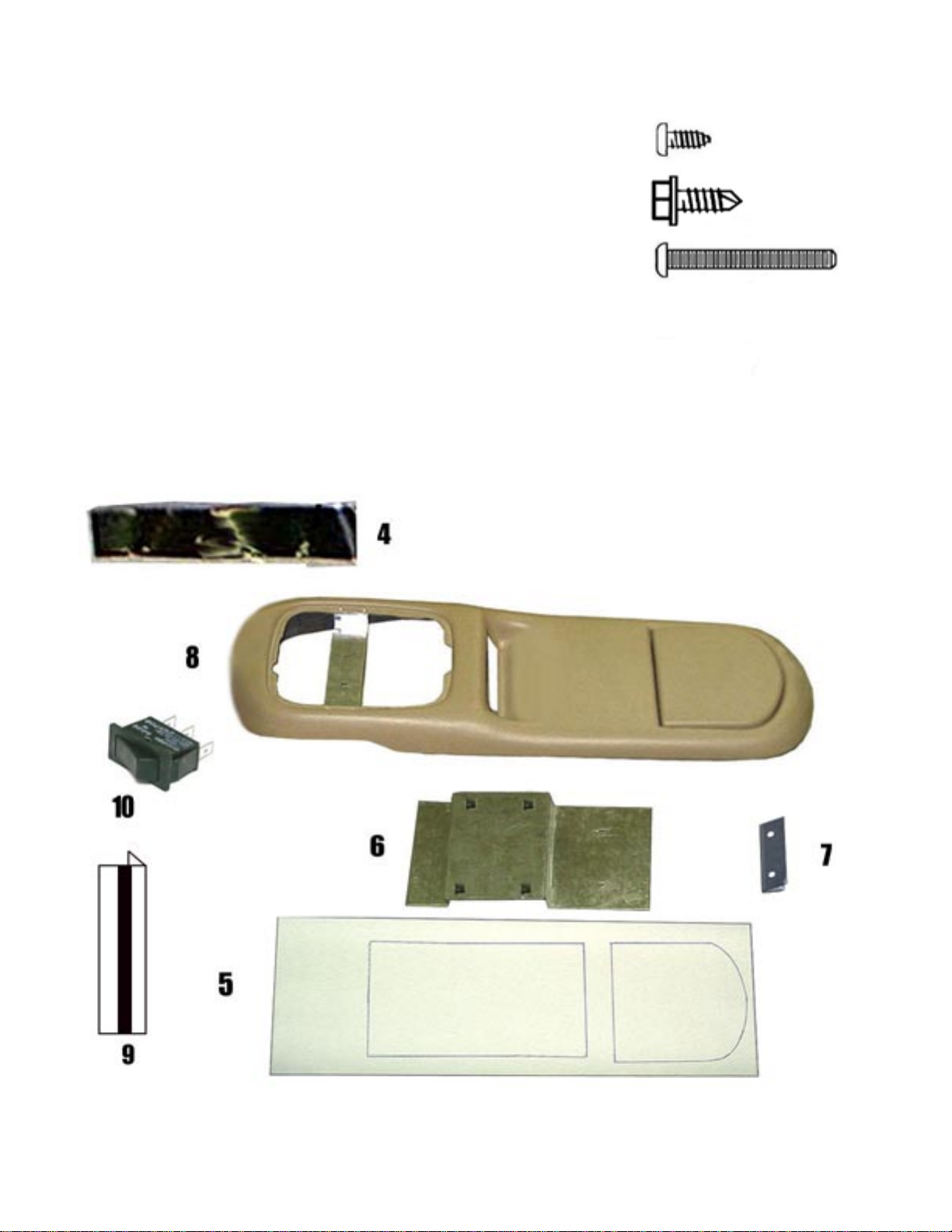
MATERIALS PROVIDED FOR
INSTALLATION:
ITEM Description QTY 1
1
2
3
4
5
6
7
8
9
10
SCREW, # 6 x 3/8" PPH
SCREW, #10 X 1/2" HWH
SCREW, 8-32 X 1 1/2" PPH
VELCRO TAPE, 1" X 6"
TEMPLATE
FRONT MOUNTING BRACKET
REAR MOUNTING BRACKET
A/C CONTROL MOUNTING BRACKET
CONSOLE
SWITCH, SPDT
2
6
4 2
1
1
1 3
1
1
1
1
INSTALLATION INSTRUCTION # 44-0086A
2
Page 3
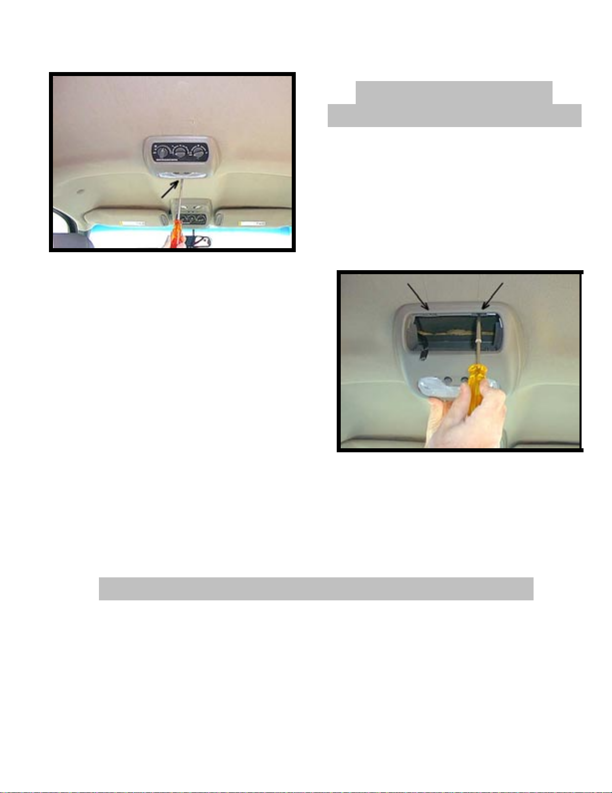
PHOTO 1
I. REMOVAL OF O.E.M.
EQUIPMENT .
1. Release front mounting clips of O.E. dome light by
gently prying downward on front edge of housing.
See Photo 1.
2. Gently lower the front of housing enough to reach inside
and push the A/C control head out of the housing.
Disconnect wiring and lay control head in a safe place.
3. Remove and discard (2) two screws which secure
housing. Disconnect wiring and discard light assembly.
See Photo 2.
II. PREPARATION OF VEHICLE INTERIOR .
PHOTO 2
INSTALLATION INSTRUCTION # 44-0086A
Jan. 1, 2001
Printed in the U.S.A.
3
Page 4

4. Using a razor knife, carefully trim headliner as
shown to allow clearance for mounting bracket.
See Photo 3. Locate template (item 5 pg 2) at
front edge of O.E. cut out. Make sure that arrow is
pointing forward and template is centered left to
right in vehicle.
PHOTO 4
5. Squeeze clips on O.E. plastic bracket and pull downward.
Pull down on outer edges of bracket to release hook and
loop fasteners. Remove and discard plastic bracket.
See Photo 4.
PHOTO 3
4
Page 5

6. Install front mounting bracket (item 6 pg 2) by aligning
holes in bracket with holes in O.E. roof brace. Secure
(4) four # 10 x 1/2" screws (item 2 pg 2). See Photo 5.
7. Install rear mounting bracket ( item 7 pg 2) on O.E. roof
brace and secure using (2) two # 10 x 1/2" screws (item 2
pg 2). Make sure bracket is centered left to right.
See Photo 6.
PHOTO 5
8. Construct a 1ft. jumper harness that will connect
the vehicle’s dome light wires to the lights in LCD
monitor housing. Refer to wiring/connections section
of the TMX-680A owner’s manual for details.
9. Using a test light, test function of lights.
using
10. Install and route all video and audio cables, and any
other added component requirements to their
respective places in the vehicle. Refer to component
installation instructions for wiring diagrams. The
suggested routing of the video system cable is as
follows: Above the headliner from video system to B-
PHOTO 6
5
Page 6

pillar. Down the B-pillar to the floor. Route the power lead to an accessory controlled source. Connect the
ground lead to the vehicle chassis. Route the remaining wiring to the VCP location. See Photo 7. Connect per
instructions included with the video system.
II
IIIIIIIIII.... PPPPRRRREEEEPPPPAAAARRRRAAAATTTTIIIIOOOONNNN OOOOFFFF CCCCOOOONNNNSSSSOOOOLLLLEEEE
11. Install O.E. A/C control head in console (item 8 pg 2).
Remove protective backing from adhesive strips on
PHOTO 7
mounting brackets (item 9 pg 2 ) and press firmly
against control head as shown. See Photo 8.
IV. INSTALLATION OF
PHOTO 10
CONSOLE .
Caution: Use extra support for the
console until secured to the
vehicle.
Failure to do so may cause damage to console or installed components.
.
PHOTO 8
12. Install dome light switch (item 10 pg 2) into opening
on front of console. Raise console into approximate
position and connect A/C control wires. Insert bracket
on rear of console into rear mounting bracket (item 7 pg 2)
and slide rearward. Position console against headliner.
Make sure console alignment is straight and matches
contours in headliner, then secure console using (2) two
# 6 x 3/8" screws (item 1 pg. 2) through the slots in
bracket on console into holes on front mounting bracket.
See Photo 9.
13. Release LCD monitor panel from locked position. Lower to viewing position for access to mounting
PHOTO 9
6
Page 7

location in top of housing.
14. Raise monitor housing into approximate position and connect all wiring to components. Connect
wiring and cabling per instructions included with LCD monitor.
15. Check function of all component and lights. See operating instructions for video operations check.
For further assistance, refer to the TMX-R680A owner’s manual for the technical support phone
number listed for your area.
16. Insert monitor housing into opening in console.
Note : Make sure wires do not get pinched
between housing and console. Align holes in
housing with clips in mounting bracket. Secure
using (4) four 8-32x 1 1/4" screws (item 3 pg.2).
See Photo 10.
Caution : Do not overtighten screws.
17. Raise LCD monitor panel into locked position.
18. Cut Velcro tape (item 4 pg 2) into 2" pieces. Remove
protective backing from tape and apply to remote
controls. Position them against the console door and
press firmly on remote while holding the door.
19. Raise remote control door into locked position.
PHOTO 11
7
 Loading...