

Page 1
ALPINE ELECTRONICS, INC.
Tokyo office ; 1-1-8 Nishi Gotanda,
Shinagawa-ku, Tokyo 141-8501, Japan
Tel.: (03) 3494-1101
ALPINE ELECTRONICS OF AMERICA, INC.
19145 Gramercy Place, Torrance,
California 90501, U.S.A.
Tel.: 1-800-ALPINE1 (1-800-257-4631)
1-888-NAV-HELP (1-888-628-4357)
ALPINE ELECTRONICS OF CANADA, INC.
Suite 203, 7300 Warden Ave. Markham, Ontario
L3R 9Z6, Canada
Tel.: 1-800-ALPINE1 (1-800-257-4631)
ALPINE ELECTRONICS OF AUSTRALIA PTY. LTD.
6-8 Fiveways Boulevarde Keysborough Victoria 3173,
Australia
Tel.: (03) 9769-0000
ALPINE ELECTRONICS GmbH
Kreuzerkamp 7-11 40878 Ratingen, Germany
Tel.: 02102-45 50
ALPINE ITALIA S.p.A.
Via C.Colombo 8, 20090 Trezzano
Sul Naviglio MI, Itary
Tel.: 02-48 47 81
ALPINE ELECTRONICS FRANCE S.A.R.L.
98, Rue De La Belle Etoile, Z.I. Paris Nord II B.P.50016
F-95945, Roissy, Charles De Gaulle Cedex, France
Tel.: 01-48 63 89 89
ALPINE ELECTRONICS OF U.K., LTD.
13 Tanners Drive, Blakelands,
Milton keynes MK14 5BU, U.K.
Tel.: 01908-61 15 56
INSTALLATION INSTRUCTION # ALA440089 Printed in U.S.A INSTALLATION INSTRUCTION # ALA440089 Printed in U.S.A
ALPINE ELECTRONICS DE ESPANÃ, S.A.
Portal De Gamarra 36, Pabollón 32
01013 Vitoria(Alava)-Apdo. 133, Spain
Tel.: 34-45-283588
Semi-Universal Trim Ring
INSTALLATION MANUAL
KTC-111GY
KTC-111TN
8
Page 2
NOTE: These instructions are intended for experienced professional installers within mobile
electronics industry. Specialized tools and equipment, as well as careful handling of product during
installation may be required. Before beginning this installation, carefully read through the following
instructions. Use extreme care when cutting headliner material. Check for wiring or other
critical components above headliner material, and cut only where indicated.
Materials/Tools required for this installation:
1. Phillips Screwdriver
2. Powered Screwdriver or drill with adapter
3. Awl or scribe point tool or similar
4. Razor knife or other appropriate cutting tool
5. ¼” Hex socket bit
6. Alpine TMX-R680A Mobile Overhead Monitor
III. INSTALLATION OF CONSOLE
Caution: Use support for the console until secured to the vehicle.
Failure to do so may cause damage to console or installed components.
2 7
26. Raise monitor housing into approximate position and connect all wiring to components. Connect wiring
and cabling per instructions included with LCD monitor. Caution: Check for clearance of dome light
switch terminals and other wiring to prevent possibility of a short circuit.
27. Check function of all components and lights. See operating instructions for video operations check.
For further assistance, refer to the TMX-R680A owner’s manual for the technical support phone
number listed for your area.
28. Adjust position of console to match contours in headliner and secure to threaded clips in
mounting bracket assembly. Caution: If spacers are not cut to proper length, over tightening
may
cause headliner to buckle. Screw & spacer assembly should be snug, preventing rocking or
vibration.
29. Raise LCD monitor panel into locked position.
PHOTO 11
19. The plain plastic trim ring may be painted or covered
with material if desired. Additionally, the vinyl covered
low profile trim ring my be dyed for color matching.
20. Insert the LCD monitor into the trim ring and secure
using screws provided with monitor. See Photo 7.
21. Install dome light switch (item 13 pg 3) in opening in
front of console.
Page 3

22. To determine the length of spacers (item 9 pg 3) and
screws that will be needed, place a straight edge across
the console and measure to each
mounting boss as shown. See Photo 8.
Mark each spacer and screw appropriately, then
trim to measured length. See Photo 8.
Caution: If screws extend more than 1" past the
edge of console, damage to roof of vehicle
PHOTO 7
may occur. Trim screws as necessary.
23. If spacers and screws are different lengths, be sure
make note of proper location for correct
installation.
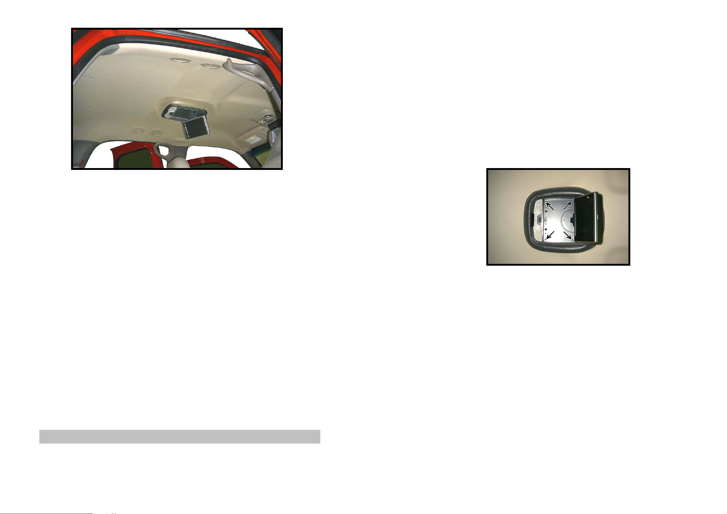
24. Release LCD monitor panel from locked position.
Lower to viewing position to access mounting
locations. Install (4) four proper length 8-32 screws
(item 3 or 8 pg 3), (4) four # 8 lock washers (item 4
PHOTO 8
pg 3), and (4) four plastic spacers (item 9 pg 3) previously cut. See Photo 9 & 10.
25. Place fender washer (item 6 pg 3) and push on retainer (item 5 pg 3) over screws as shown.
See Photo 9 & 10.
4
5
6
7
8
9
10
11
12
13
14
SPLIT LOCK WASHER, # 8
PUSH ON RETAINER
FENDER WASHER
NUT, 8-32, KEPS
SCREW, 8-32 X 3 1/2" PPH
PLASTIC SPACER, 1/4" X 1/2" X 3"
MOUNTING BRAKET
CONSOLE, VINYL COVERED
CONSOLE, PLASTIC ONLY
SWITCH, SPDT
CONSOLE MOUNTING BRACKET
4
4
4
4
4
4
1
1
1
1
1
MATERIALS PROVIDED FOR INSTALLATION:
ITEM Description QTY
PHOTO 9
1
2
3
SCREW, 8-32 X 3/8" PPH
SCREW, #10 X 3/4" HWH
SCREW, 8-32 X 1 1/2" PPH
I. PREPARATION OF VEHICLE INTERIOR
PHOTO 10
4
6
4
4
1. Determine which console is to be used, the low profile
vinyl covered console (item 11 pg 3) for relatively flat
headliners or high profile plastic only console (item 12
pg 3) for heavily contoured headliners.
2. Insert the TMX-R680A LCD monitor in the console
and secure using (4) four screws provided with monitor. See Photo 1.
3
Page 4

3. Release LCD monitor panel from locked position. Lower to viewing position.
4. Determine a suitable mounting location by raising
console into approximate position and checking the
viewing angle from the rear seat, contours in headliner,
that THE MONITOR CAN NOT BE
VIEWED BY THE DRIVER,
AND THAT THE
MONITOR WILL NOT IMPROPERLY LIMIT
REAR VIEW MIRROR FUNCTIONS. ENSURE
COMPLIANCE WITH ALL APPLICABLE
SAFETY STANDARDS GOVERNING THE
FUNCTION OF THE REAR VIEW MIRROR, THE
DRIVER’S FIELD OF THE VIEW AND THE
PHOTO 1
PASSENGER’S SAFETY.
5. Mark location on headliner with masking tape.
6. If mounting location is over the dome light, remove
light and disconnect wiring.
7. Locate the vehicle’s roof brace and determine how
close it is to the center of the console.
8. If the roof brace is close to center, you can use just the
center bracket of the mounting bracket assembly
(item 14 pg 3). If the roof brace is in front of the
console, you will need to locate a second roof brace.
PHOTO 2
The mounting bracket assembly can be adjusted to span up to 29" between braces. If a span of more than 13"
is required, the headliner may need to be lowered to gain access to the rear mounting screws.
9. Using a razor knife, carefully trim headliner as shown
to allow clearance for mounting bracket. Make sure
location is centered left to right. See Photo 3.
Caution: Before cutting headliner material, check
for wiring or other critical components above
headliner. DO NOT OVERCUT HEADLINER.
10. Make necessary adjustments to the mounting bracket assembly and install in vehicle. Use additional
screws and nuts (items 1 & 7 pg 3) if necessary. Make sure that bracket is centered left to right and
secure using (4) four # 10 x 3/4" screws (item 2 pg 3).
Caution: Make sure that roof brace is at least 3/4" tall. If not, substitute a shorter screw or
damage to roof may occur. See Photo 4.
11. Prepare connection of the vehicle’s dome light wires to the monitor for proper function. Note: Vehicle
dome light +12V constant may not provide sufficient current for both monitor and integrated
lights. Direct connection to battery may be required. Refer to wiring/connections section of the
TMX-R680A owner’s manual for details.
PHOTO 3
4 5
12. Using an analog or digital multi-meter, test the
function of the dome lights.
13. Install and route all video and audio cables, and any
other added component requirements to their respective
places in the vehicle. Refer to component installation
instructions for wiring diagrams. The suggested routing
of the video system cable is as follows: Above the
headliner from video system to the B-pillar. Down the
B-pillar to the floor. See Photo 5. Connect per
instructions included with the video system and the
TMX-R680A owner’s manual.
II. PREPARATION OF
TRIM RING
18. Carefully trim the console with an appropriate cutting
tool (e.g. jigsaw, razor knife, etc). Check the fit of
console and make any necessary changes.
PHOTO 5
PHOTO 4
14. The console may need to be trimmed to fit the
contour
of the headliner. Apply masking tape to the
console.
15. Tape a pen or pencil to the handle of a
screwdriver to
make a contour marking tool. See Photo 6.
16. Raise console into approximate position and
trace
around console. See Photo 6.
17. Remove LCD monitor housing from console
and set it
in a safe place.
PHOTO 6
 Loading...