

Technical Manual
CE-3x2 5K-T 48Vdc Telecom Generator
PN-6x-T 7.5kW 48Vdc Telecom Generator
Effective: May 2008
Alpha Technologies

Alpha Technologies
Power
®

TM
CE-3x2 5K-T 48Vdc Telecom Generator
PN-6x-T 7.5kW 48Vdc Telecom Generator
Technical Manual
042-288-B0-001, Rev. A
Effective Date: May 2008
Copyright © 2008
Alpha Technologies, Inc.
member of The Group
NOTE:
Photographs contained in this manual are for illustrative purposes only. These photographs may not match
your installation.
NOTE:
Operator is cautioned to review the drawings and illustrations contained in this manual before proceeding. If
there are questions regarding the safe operation of this powering system, please contact Alpha Technologies
or your nearest Alpha representative.
NOTE:
Alpha shall not be held liable for any damage or injury involving its enclosures, power supplies, generators,
batteries, or other hardware if used or operated in any manner or subject to any condition not consistent with
its intended purpose, or is installed or operated in an unapproved manner, or improperly maintained.
TM
Contacting Alpha Technologies: www.alpha.com
or
For general product information and customer service (7 AM to 5 PM, Pacifi c Time), call
1-800-863-3930,
For complete technical support, call
1-800-863-3364
7 AM to 5 PM, Pacifi c Time or 24/7 emergency support
3

Table of Contents
Safety Notes .......................................................................................................................... 8
1.0 System Overview ...................................................................................................... 13
1.1 PN-6x-T System Diagram ..............................................................................14
1.2 CE3x2 5kW System Diagram ........................................................................15
1.3 Natural Gas System Block Diagram .............................................................. 16
1.4 Liquid Propane System Block Diagram ......................................................... 17
1.5 Specifi cations ................................................................................................. 18
2.0 Site Preparation ........................................................................................................ 21
2.1 Site Considerations ........................................................................................21
2.2 Acoustics ........................................................................................................21
2.3 Enclosure Impact Protection .......................................................................... 23
2.4 Natural Gas Meter Confi gurations ................................................................. 25
2.5 Liquid Propane Systems ................................................................................ 27
2.6 Grounding Requirements, CE-3x2 5K-T ........................................................ 28
2.7 Grounding Requirements, PN-6xT 7.5kW ..................................................... 29
3.0 Installation.................................................................................................................30
3.1 Installing the CE-3x2 5K-T or PN-6x-T 7.5kW Pad Template ........................ 30
3.2 Installation, CE-3x2 5K-T ............................................................................... 33
3.2.1 CE-3x2 5K-T Transportation and Lifting .............................................. 34
3.2.2 Enclosure Installation, CE-3x2 5K-T ................................................... 36
3.3 PN-6x-T 7.5kW Installation ........................................................................... 37
3.3.1 PN-6x-T 7.5kW Transportation and Lifting, ......................................... 38
3.3.2 Enclosure Installation Procedure, PN-6x-T 7.5kW ..............................40
3.4 Enclosure Grounding, CE-3x2 5K-T .............................................................. 41
3.5 Enclosure Grounding, PN-6x-T 7.5kW ........................................................... 42
3.6 Natural Gas Utility Fuel Hookup, CE-3x2 5K-T ..............................................43
3.7 Natural Gas Utility Fuel Hookup, PN-6x-T 7.5kW .......................................... 44
3.8 Liquid Propane Utility Fuel Hookup, CE-3x2 5K-T .........................................45
3.9 Liquid Propane Utility Fuel Hookup, PN-6x-T 7.5kW ..................................... 46
3.10 Making the DC Output Connection, CE-3x2 5K-T ......................................... 47
3.11 Making the DC Output Connection, PN-6x-T 7.5kW ...................................... 48
3.12 Connecting the Ignition Battery, CE-3x2 5K-T ...............................................49
3.13 Connecting the Ignition Battery, PN-6x-T 7.5kW ...........................................50
3.14 Terminal Block 2 (AC Line) Connections, CE-3x2 5K-T .................................51
3.15 Terminal Block 2 (AC Line) Connections, PN-6x-T 7.5kW ............................. 52
3.16 Final Inspection Checklist .............................................................................. 53
4.0 The Engine Control Module ..................................................................................... 54
4.1 Theory of Operation ....................................................................................... 56
4.1.1 Standby Operating Condition Less Than Three Minutes .................... 56
4.1.2 Standby Operating Condition More Than Three Minutes .................... 56
4.1.3 Normal APU Shutdown ....................................................................... 57
4.1.4 Abnormal APU Shutdown.................................................................... 57
4.2 ECM Operating Mode Summary ....................................................................57
4.3 LED Indicators ............................................................................................... 58
4
042-288-B0-001, Rev. A

4.4 Control Functions ...........................................................................................59
4.5 Alarm Classifi cations ...................................................................................... 60
4.6 ECM Alarm Overview ..................................................................................... 62
4.7 Connecting the Alarm and Control Connections ............................................63
4.8 ECM DIP Switch and Fuse Confi guration ......................................................64
4.9 ECM Interface Block Diagram and Connectors ............................................. 66
4.10 ECM Self-test ................................................................................................. 67
4.11 Maintenance Functions .................................................................................68
5.0 Turn-up and Test ....................................................................................................... 69
5.1 Appearance and Condition of Components ................................................... 69
5.2 System Preparation ....................................................................................... 69
5.3 Performing a Local APU Test ......................................................................... 70
5.4 Generator System Sensor Verifi cation ........................................................... 71
5.4.1 Enclosure Alarm Verifi cation ............................................................... 71
5.4.2 AC and DC Line Sense Verifi cation ....................................................72
6.0 Operation ..................................................................................................................73
6.1 Normal Operating Condition .......................................................................... 73
6.1.1 AC Line Fail ......................................................................................... 73
6.1.2 Low DC Bus Level............................................................................... 73
6.2 Alpha Ignition Battery Charger Overview .......................................................74
7.0 Maintenance ............................................................................................................. 75
7.1 Servicing the APU .......................................................................................... 76
7.2 Filter Cleaning, CE-3x2 5K-T ......................................................................... 77
7.3 Filter Cleaning, PN-6x-T 7.5kW ..................................................................... 78
7.4 Pad Shear Magnetic Switch Replacement..................................................... 79
7.5 Replacing Gas Hazard Sensor ...................................................................... 80
7.6 Replacing Ignition Battery Charger Module Assembly ................................... 81
7.7 Replacing Engine Control Module ................................................................ 82
7.8 Fuel Conversion, Natural Gas to LP .............................................................. 83
7.8.1 PN-6x-T Pre-regulator Removal with Low Pressure Switch Installation ...... 83
7.8.2 Switching the LP Port to the NG Port, PN-6x-T .................................. 84
7.8.3 Switching the NG Port to the LP Port, CE-3X2 ................................... 85
7.9 Maxitrol Pre-regulator Calibration .................................................................. 86
8.0 Interconnection ......................................................................................................... 89
8.1 Gas Hazard Alarm Interface Connector .........................................................89
8.2 Low Fuel Pressure Interface Connector ........................................................ 89
8.3 Gas Solenoid Interface Connector ................................................................ 92
8.4 Charger Module Control Interface Connector ............................................... 90
8.5 ECM Enclosure Alarm Interface Connector ................................................... 91
8.6 Inverter Battery DC Sense Interface Connector ............................................ 91
8.7 Charger Control Interface Connector .............................................................92
8.8 ECM AC Line Sense 120/240V Interface ....................................................... 92
8.9 ECM APU Control Interface ........................................................................... 93
8.10 ECM Alarm Interface ...................................................................................... 93
042-288-B0-001, Rev. A
5

List of Figures
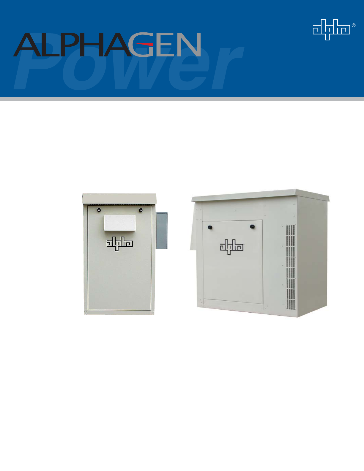
Fig. 1-1, PN-6x-T 7.5kW Telecom Generator ...................................................................... 13
Fig. 1-2, CE-3x2 5K-T Telecom Generator .......................................................................... 13
Fig. 1-3, PN-6x-T System Diagram ..................................................................................... 14
Fig. 1-4, CE3x2 System Diagram ........................................................................................ 15
Fig. 1-5, Arrangement of Metered, Nominal Pressure (1-2psi) Natural Gas System........... 16
Fig. 1-6, Excess Flow Valve ...............................................................................................16
Fig. 1-7, LP Propane Vapor Withdrawal Block Diagram ...................................................... 17
Fig. 2-1, Generator Sound Levels at 100% Load ................................................................ 21
Fig. 2-2, Acoustical Measurements in Relation to Placement Near Residences ................. 22
Fig. 2-3, Vehicular Area Impact Protection for Collocated Natural Gas Meter ................... 23
Fig. 2-4, Vehicular Area Impact Protection for Remote Natural Gas Meter ........................ 24
Fig. 2-5, Collocated Natural Gas Meter Setup for CE-3x2 Generator ................................. 25
Fig. 2-6, Collocated Natural Gas Meter Setup for PN-6x-T 7.5kW System .........................25
Fig. 2-7, Collocated CE-3x2 5K-T Generator with Remote Natural Gas Meter ................... 26
Fig. 2-8, Remote Natural Gas Meter Setup for PN-6x-T 7.5kW Generator ......................... 26
Fig. 2-9, Liquid Propane Setup, CE-3x2 5K-T ..................................................................... 27
Fig. 2-10, Liquid Propane Setup, PN-6x-T 7.5kW ............................................................... 27
Fig. 2-11, Enclosure Grounding, CE-3x2 5K-T .................................................................... 28
Fig. 2-12, Enclosure Grounding, PN-6x-T 7.5kW ................................................................ 29
Fig. 3-1, Pad Frame Template for CE-3x2 5K-T .................................................................. 30
Fig. 3-2, Pad frame and mounting template CE-3x2 5.0 kW .............................................. 31
Fig. 3-3, Cross-section of Sweep Trench ............................................................................ 32
Fig. 3-4, Pad Bolt Location, CE-3x2 5K-T ........................................................................... 34
Fig. 3-5, Lifting Ear Attachment ........................................................................................... 35
Fig. 3-6, Enclosure with Lifting Ears Installed, CE-3x2 5K-T ...............................................36
Fig. 3-7, Water Intrusion Alarm (1), Pad Shear Sensor (2), and Pad Shear Magnet (3) .....36
Fig. 3-8, PN-6x-T 7.5kW Sweep Dimensions (in inches) .................................................... 37
Fig. 3-9, Pallet Bolt Locations, PN-6x-T 7.5kW ................................................................... 38
Fig. 3-10, Enclosure with Lifting Ears Installed, PN-6x-T 7.5kW ......................................... 39
Fig. 3-11, Installation Location of Pad Shear/Magnet Assembly .........................................40
Fig. 3-12, Enclosure Grounding, CE-3x2 5K-T ....................................................................41
Fig. 3-13, Enclosure Grounding, PN-6x-T 7.5kW ............................................................... 42
Fig. 3-14, Utility Gas Service Input, CE-3x2 5K-T ............................................................... 43
Fig. 3-15, Utility Gas Service Input, PN-6x-T 7.5kW ........................................................... 44
Fig. 3-16, Propane Fuel Hookup, CE-3x2 5K-T ................................................................... 45
Fig. 3-17, Propane Fuel Hookup, PN-6x-T 7.5kW ...............................................................46
Fig, 3-18, DC Output, CE-3x2 5K-T ..................................................................................... 47
Fig. 3-19, DC Output Safety Shroud.................................................................................... 48
Fig. 3-20, DC Output Connections, PN-6x-T 7.5kW ............................................................48
Fig. 3-21, Terminal Block 2 (TB2) Position 1, 5kW .............................................................. 51
Fig. 3-22, Terminal Block 2 (TB2), PN-6x-T7.5kW ..............................................................52
6
042-288-B0-001, Rev. A

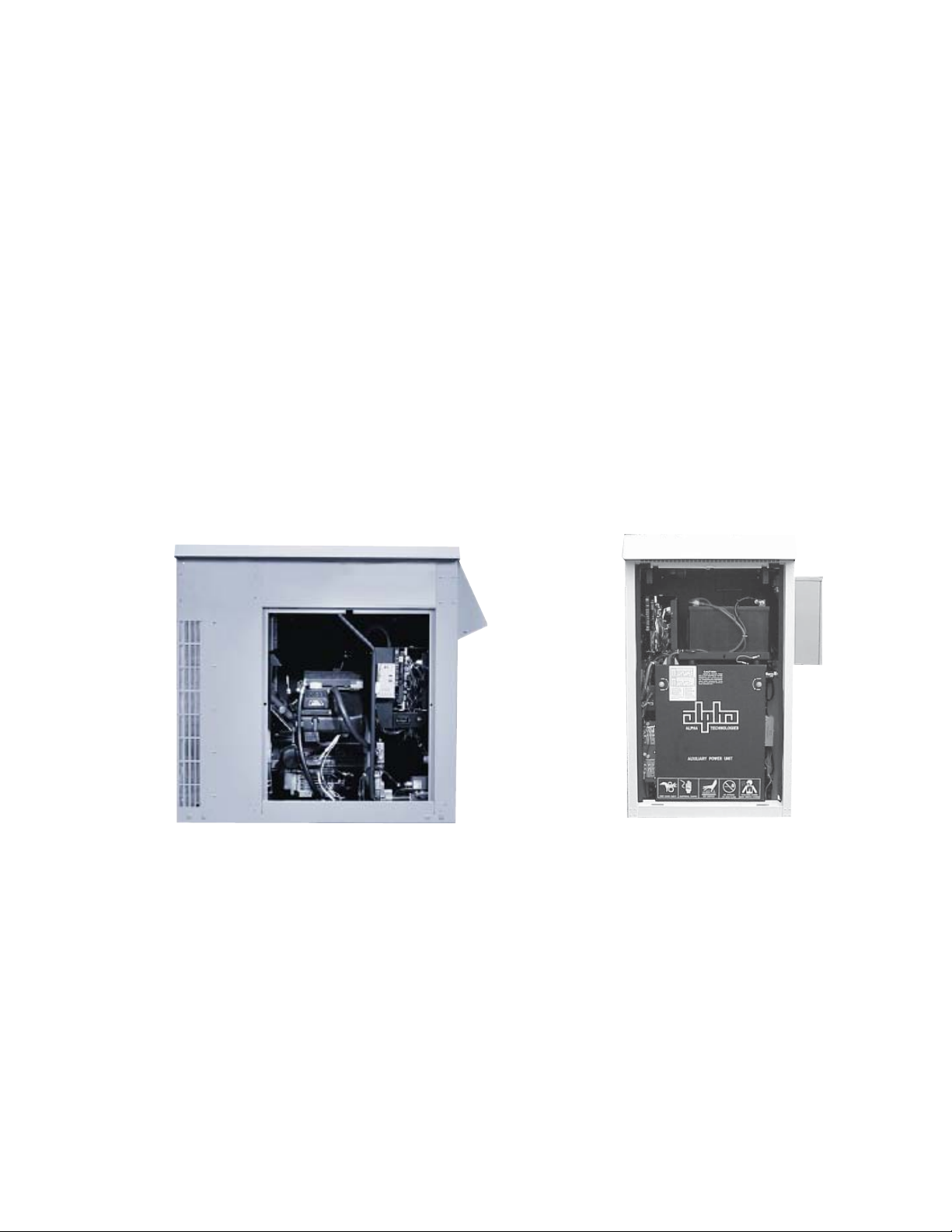
Fig. 4-1, Location of Engine Control Module (ECM) ...........................................................54
Fig. 4-2 (a), ECM LED Indicators, Switches, and Interface Connections ............................ 55
Fig. 4-2 (b), ECM Printed Circuit Boards ............................................................................ 55
Fig. 4-3, LED Indicators and Control Functions...................................................................59
Fig. 4-4, Terminal Block 1 .................................................................................................... 63
Fig. 4-5, SW5 and Fuse Locations ...................................................................................... 64
Fig. 4-6, SW5 Settings.........................................................................................................65
Fig. 4-7, ECM/APU Interconnection ................................................................................... 66
Fig. 5-1, Generator Set Master Switch and Run/Auto/Stop (RAS) Switch .......................... 70
Fig. 6-1, Ignition Battery Charger LED ................................................................................ 74
Fig. 6-2, Wiring for ECM, Ignition Battery Charger, and Ignition Battery ............................. 74
Fig. 7-1, Captive Fastener Location, CE-3x2 5K-T .............................................................. 77
Fig. 7-2, Air Filter Removal, CE-3x2 5K-T ........................................................................... 77
Fig. 7-3, Filter Replacement, PN-6x-T 7.5kW ...................................................................... 78
Fig. 7-4, Pad Shear Sensor ................................................................................................. 79
Fig. 7-5, Gas Hazard Sensor Location (Alpha P/N 744-891-20) ......................................... 80
Fig. 7-6, Ignition Battery Charger ........................................................................................ 81
Fig. 7-7, ECM ...................................................................................................................... 82
Fig. 7-8, PN-6x-T Pre-regulator Removal ............................................................................83
Fig. 7-9, PN-6x-T Switch Assembly Installed ....................................................................... 83
Fig. 7-10, Load Block, PN-6x-T 7.5kW ................................................................................ 84
Fig. 7-11, Changing Load Block Confi guration, PN-6x-T 7.5kW .........................................84
Fig. 7-12, Changing Load Block Confi guration, CE-3x2 5K-T ............................................. 85
Fig. 7-13, Primary Fuel Regulator ....................................................................................... 86
Fig. 7-14, Pre-regulator Calibration ..................................................................................... 87
Fig. 7-15, Secondary Demand Regulator ............................................................................ 87
Fig. 7-16, Manometer Connection ....................................................................................... 88
Fig. 8-1, Gas Hazard Detector Interface Connector ............................................................ 89
Fig. 8-2, Low Fuel Pressure Interface Connector ................................................................89
Fig. 8-3, Gas Solenoid Interface Connector ........................................................................ 90
Fig. 8-4, Charger Control Interface Connector .................................................................... 90
Fig. 8-5, ECM Enclosure Alarm Interface Connector...........................................................91
Fig. 8-6, Inverter Battery DC Sense Interface Connector ....................................................91
Fig. 8-7, Charger Control Interface Connector .................................................................... 92
Fig. 8-8, ECM AC Line Sense, 120/240V Interface ............................................................. 92
Fig. 8-9, APU Control Interface............................................................................................93
Fig. 8-10, ECM Connector Arrangement ............................................................................. 93
042-288-B0-001, Rev. A
7

Safety Notes
Review the drawings and illustrations contained in this manual before proceeding. If there are any questions
regarding the safe installation or operation of the system, contact Alpha Technologies or the nearest Alpha
representative. Save this document for future reference.
To reduce the risk of injury or death, and to ensure the continued safe operation of this product, the following
symbols have been placed throughout this manual. Where these symbols appear, use extra care and
attention.
ATTENTION:
The use of ATTENTION indicates specifi c regulatory/code requirements that may affect the placement of
equipment and installation procedures.
NOTE:
A NOTE provides additional information to help complete a specifi c task or procedure.
CAUTION!
The use of CAUTION indicates safety information intended to PREVENT DAMAGE to material or
equipment.
WARNING!
A WARNING presents safety information to PREVENT INJURY OR DEATH to the
technician or user.
8
042-288-B0-001, Rev. A

General Safety Precautions
To avoid injury:
• This enclosure and its associated hardware must be serviced only by authorized personnel.
• Enclosure must remain locked at all times, except when authorized service personnel are present.
• Remove all conductive jewelry or personal equipment prior to servicing equipment, parts, connectors,
wiring, or batteries.
• Read and follow all installation, equipment grounding, usage, and service instructions included in this
manual.
• Use proper lifting techniques whenever handling enclosure, equipment, parts, or batteries.
• Batteries contain dangerous voltages, currents and corrosive material. Battery installation, maintenance,
service and replacement must be performed by authorized personnel only.
• Never use uninsulated tools or other conductive materials when installing, maintaining, servicing or
replacing batteries.
• Use special caution when connecting or adjusting battery cabling. An improperly connected battery cable,
or unconnected battery cable, can result in arcing, fi re, or possible explosion.
• A battery that shows signs of cracking, leaking or swelling must be replaced by authorized personnel
immediately using a battery of identical type and rating.
• Avoid any contact with gelled or liquid emissions from a valve-regulated lead-acid (VRLA) battery.
Emissions contain dilute sulfuric acid that is harmful to the skin and eyes. Emissions are electrolytic, and
are electrically conductive and are corrosive. Follow the Chemical Hazards notes if contact occurs.
• Do not smoke or introduce sparks in the vicinity of the batteries or natural gas/propane connections.
• Under certain overcharging conditions, lead-acid batteries can vent a mixture of hydrogen gas that is
explosive. Proper venting of the enclosure is required.
• Follow the battery manufacturer’s approved transportation and storage instructions.
To avoid damage:
• Prior to installation, verify that the AC input voltage to the enclosure and its equipment match with respect
to voltage and frequency.
• Prior to installation, verify that the output voltage from the enclosure or its equipment match the voltage
requirements of the connected equipment (load).
• Prior to installation, verify that the enclosure’s utility service panel is equipped with a properly rated circuit
breaker for use with the equipment inside. Refer to manufacturer’s recommendations.
• Review and upgrade utility service panel circuit breaker requirements whenever the equipment within the
enclosure is changed.
• Prior to installation, contact local utilities, local building maintenance departments, and cable/piping
locator services to ensure that installation does not interfere with existing utility or building cables/piping.
• Do not exceed the output rating of equipment. Verify load requirements prior and during connection
process.
• Prior to handling the batteries, touch a grounded metal object to dissipate any static charge that may
have developed in your body.
042-288-B0-001, Rev. A
9

Battery Safety Notes
WARNING!
Lead-acid batteries contain dangerous voltages, currents, and corrosive material. Battery
installation, maintenance, service, and replacement must only be performed by authorized
personnel.
Chemical Hazards
Any gelled or liquid emissions from a valve-regulated lead-acid (VRLA) battery contain dilute sulfuric
acid, which is harmful to the skin and eyes. Emissions are electrolytic, and are electrically conductive and
corrosive.
To avoid injury:
• Servicing and connection of batteries shall be performed by, or under the direct supervision of, personnel
knowledgeable of batteries and the required safety precautions.
• Always wear eye protection, rubber gloves, and a protective vest when working near batteries. Remove
all metallic objects from hands and neck.
• Batteries produce explosive gases. Keep all open fl ames and sparks away from batteries.
• Use tools with insulated handles. Do not rest any tools on top of batteries.
• Batteries contain or emit chemicals known to the State of California to cause cancer and birth defects,
or other reproductive harm. Battery post terminals and related accessories contain lead and lead
compounds. Wash hands after handling (California Proposition 65).
• Wear protective clothing (insulated gloves, eye protection, etc.) when installing, maintaining, servicing, or
replacing batteries.
• If any battery emission contacts the skin, wash immediately and thoroughly with water. Follow your
company’s approved chemical exposure procedures.
• Neutralize any spilled battery emission with the special solution contained in an approved spill kit or with
a solution of one pound Bicarbonate of soda to one gallon of water. Report chemical spill using your
company’s spill reporting structure and seek medical attention if necessary.
• Always replace batteries with those of an identical type and rating. Never install old or untested batteries.
• Do not charge batteries in a sealed container. Each individual battery should have at least 0.5 inches of
space between it and all surrounding surfaces to allow for convection cooling.
• All battery compartments must have adequate ventilation to prevent an accumulation of potentially
dangerous gas.
• Prior to handling the batteries, touch a grounded metal object to dissipate any static charge that may have
developed on your body.
• Never use uninsulated tools or other conductive materials when installing, maintaining, servicing, or
replacing batteries.
• Use special caution when connecting or adjusting battery cabling. An improperly connected battery cable
or an unconnected battery cable can make contact with an unintended surface and can result in arcing,
fi re, or possible explosion.
• A battery showing signs of cracking, leaking, or swelling should be replaced immediately by Authorized
Personnel using a battery of identical type and rating.
10
042-288-B0-001, Rev. A

Battery Maintenance Guidelines
The battery maintenance instructions listed below are for reference only. Battery manufacturer’s instructions
for transportation, installation, storage, or maintenance take precedence over these instructions.
• To prevent damage, inspect batteries every 3 months for:
Signs of battery cracking, leaking or swelling. The battery should be replaced immediately by
authorized personnel using a battery of the identical type and rating.
Signs of battery cable damage. Battery cables should be replaced immediately by authorized personnel
using replacement parts specifi ed by vendor.
Loose battery connection hardware. Refer to battery manufacturer’s documentation for the correct
torque and connection hardware for the application.
• Apply battery manufacturer’s specifi ed antioxidant compound on all exposed connections.
• Verify battery terminals and/or exposed connection hardware is not within 2 inches of a conductive
surface. Reposition batteries as necessary to maintain adequate clearance.
• Clean up any electrolyte (battery emission) in accordance with all federal, state, and local regulations or
codes.
• Proper venting of the enclosure is recommended. Follow the Battery Manufacturer’s approved
transportation and storage instructions.
• Always replace batteries with those of an identical type and rating. Never install old or untested batteries.
• Do not charge batteries in a sealed container. Each individual battery should have at least 0.5
inches of space between it and all surrounding surfaces to allow for convection cooling.
• All battery compartments must have adequate ventilation to prevent an accumulation of potentially
dangerous gas.
Recycling and Disposal Instructions
Spent or damaged batteries are considered environmentally unsafe. Always recycle used batteries or dispose
of the batteries in accordance with all federal, state and local regulations.
Electrical Safety
• Lethal voltages are present within the power supply and electrical boxes. Never assume that an electrical
connection or conductor is not energized. Check the circuit with a volt meter with respect to the grounded
portion of the enclosure (both AC and DC) prior to any installation or removal procedure.
• Always use the buddy system when working under hazardous conditions.
• A licensed electrician is required to install permanently wired equipment.
• Input voltages can range up to 240Vac. Ensure that utility power is disabled before beginning installation
or removal.
• Ensure no liquids or wet clothes contact internal components.
• Hazardous electrically live parts inside this unit are energized from batteries even when the AC input
power is disconnected.
Gas Safety
• Do not smoke or use any source of fl ame around gas lines. Propane and natural gas are extremely
fl ammable, and explosive at high concentrations. Large releases can create a fl ammable vapor cloud.
• In high concentrations gas is an asphyxiant that displaces oxygen from the breathing atmosphere.
• Contact with liquid may cause skin and eye burns.
042-288-B0-001, Rev. A
11

Auxiliary Power Unit (APU) Notes
• While the engine is stopping, a small amount of unburned fuel may be present. Fans are used to expel
these fumes from the enclosure, but fumes may be detected outside the enclosure for a short period of
time after engine shutdown. This is a normal condition and does not present a hazard.
• Most utilities add a chemical agent to the gas which produces a strong odor so leaks can be detected
before they reach a dangerous or explosive level. It may be possible to detect this gas additive odor even
though the gas hazard sensor does not issue an alarm. The gas sensor will issue an alarm when the
detected levels of gas reaches 10% to 20% of the Lower Explosive Limit (LEL). The gas hazard sensor
has a 10 minute delay for periods of purging and power up. During the purge phase, the Green alarm light
will fl ash. When the purge phase is completed, the light will glow steadily. In the event the detector has
been disconnected from power for more than 24 hours, it may require a period of more than 10 minutes
to complete its purge phase. In that event, push the reset button to disable the alarm for repeated purge
cycles. The reset button may be used to disable the alarm for 10 minutes at any time.
• If gas fumes are detected before running the engine, or more than 10 minutes after running the engine,
check the system for leaks and correct as necessary.
12
042-288-B0-001, Rev. A
1.0 System Overview
AlphaGen Telecom curb-side generator systems power outside plant communication networks. Every
AlphaGen system incorporates industry leading power technology, including natural gas or propane
fueling, exclusive audible noise baffl ing, remote status monitoring features, and a durable, weather
resistant enclosure construction.
This document describes the installation, operation, and maintenance of the CE-3x2 5K-T and PN-6x-T
7.5kW Telecom generators.
Features:
• Cost effective extended runtime solution for outdoor powering applications
• Quiet operation, small size, and low profi le provides for easier installation in populated areas
• Eliminates large quantities of batteries otherwise required for extended runtime
• Telecom-grade 48Vdc output
• Built-in safeguards to protect the system, operator, and public
• Safe unattended operation designed to UL2200, NFPA 37, 54, 58 & 70 standards
Fig. 1-1, PN-6x-T 7.5kW Telecom Generator
042-288-B0-001, Rev. A
Fig. 1-2, CE-3x2 5K-T Telecom Generator
13
1.0 System Overview, continued
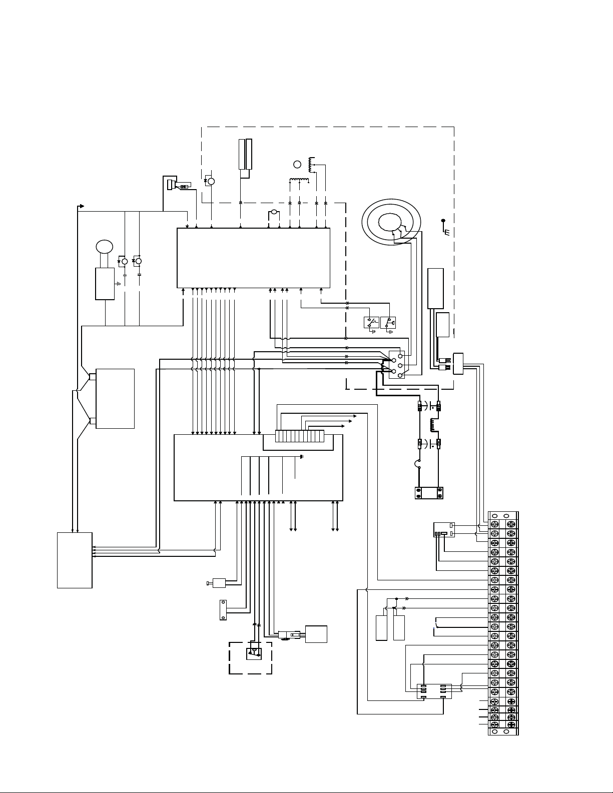
1.1 PN-6x-T System Diagram
SR
STARTER RELAY
0
1
7
N
7
0
-1
2
LP
UE
ROUND P2-2
F
G
CRANK P2-1
.
MP
PRESS.
E
L
T
RY +
TTE
3-5 BA
P
P
I
R
OW O
OVE
L
1
1
-
7
P1
P1-10 E NGINE RUNNING
P1-2 GROUND
P1-
P1 -4 OV ER CRAN K
P1-1 GROUND
P1-3 BATTERY+
P1-6 START
P1-9 STOP
TT
N
VC
N
P
S
STP
LOP
OVT
O
RUN
BCA
Battery Charging
Regulator
HR
SM
SS
SS
SR
P
P
IGNITION MODULE
QCON1
IGN
3
NP2-1
O
NITI
IG
D
EE
P
1-12 O VERS
P
OVS
IGNITION MODULE
HR
70
GAUGES P2-6
CONTROL
PCB
SPEED SENSING
P3- 4
P3-3
AC1
AC2
STM
YEL
RED
P7- 2
M4
P2-16
7
-1
2
P
37
THROTTLE
INHIBIT FOR
P7-4
P7-1
M2
0
-2
2
P
L
NTRO
O
C
SECONDS AFTER
30
SECOND SHUTDOWN
START, THEN 5
2-18
P
13
WHT
M1
P2-19
NT
E
TM
R
ENGINE
COMP A
SW
P
HIGH OILTEM
R
D
ATO
EA
ST
3L
EATER
H
BLOCK
T
HO
LOP
LOW OIL PRESSURE SWITCH
OR
T
E
R
ARBU
C
R
E
HEAT
P7-3
M3
N
-12
-3
2
2
P
-) P
(
BAT
T
TPU
SING
N
SE
DCOU
P3-2
P3-1
DCP
DCN
C
A
+
D
B
-
+
IGNITION
BATTERY
-
C
NC
163
2
9
J4
M
EC
3
2
4
1
J9
K
C
RED
BLA
2
1
J1
34
J2
Y
2
1
ER
RGER
A
TT
BA
CH
BLACK
RED
J9
N
ER
SIO
T
A
TRU
W
N
I
N
487
5
YELLOW
1
R
EA
12
11
10
PADSHEAR
0
1
J
2
1 WATERINTRUSION
3
ORANGE
E
T
WHI
WHITE
RED
PADSH
L
SURESW
S
LOW FU E
PRE
1
2
5
678
3
4
3
1
B1
T
R
WE
O
ESS.
P
R
LP
E
AZARD
H
S
A
GASHAZARD
LOW F U
G
0
5
462
9
8
7
1
TE
WHI
BLACK
BLACK
K
GE
N
GREEN
RA
BLAC
O
1
2
Y
L
PG MOD EL
ON
L
9
12
1011
N
E
P
(See Fig. 3-12 for details)
O
OUND
R
NC
DOOR
12 V
G
4
1
11
13
12
-7
2
2-8
B
TB
T
R
O
S
123
S
A
G
HAZARD
SEN
AC SENSE
2
1
-2
2
B2-1
T
TB
TB2- 11
-13
2
B
T
TB2- 20
E
RECT
00 AM P CB
2
NEG
Y
A
EL
AC FAIL
R
B
C
W
UT
P
OUT
AUX S W
DOOR S
DOOR S W
S
S
Y
A
RM
A
AL
BYPA
6
8
REL
7
1
Fig. 1-3, PN-6x-T System Diagram
AC
V
120
1
2
345
6
7
8
9
0
1
11
12
13
4
1
15
6
1
17
18
19
20
21
2223
TB 2
C
L
A
C
N
A
G
AC
IL
AC/
FA
COM
O
AIL
AC/
F
N
/
IL
A
NC
AC
F
LPG
(12V)
G
P
(-)
L
r
OM
Doo
C
O
oor
N
D
M
R
NO
COM
MINOR
ALA
M
R
NC
MINOR
ALA
NO
MINOR
ALARM
NC
ENG
RUN
N
NO
ENG
RU
ENG
RUN
COM
BY
NC
ALM
M
BY
NO
AL
M
O
BY
ALM
C
NC
COM
MINOR
ALARM
R
M
O
C
ALARM
RM
NO
ALA
M
R
A
NC
L
MAJORMAJORMAJO
A
POS
L
COM
NC
NO
N
COM
NC
NO
2
4
3
0
9
TB1
ECM
4
1-
CM
B
T
E
5
M
1-
C
B
T
E
-6
ECM
TB1
14
042-288-B0-001, Rev. A
1.0 System Overview, continued
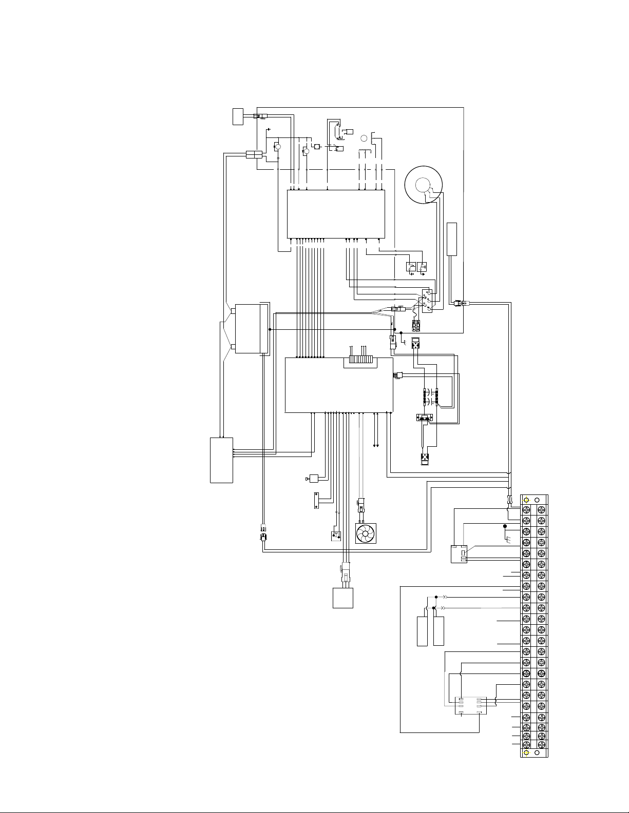
1.2 CE3x2 5kW System Diagram
FUEL
SOLENOID
P8
+
IGNITION
BATTERY
-
RED
BLACK
2
1
P5
SM
BLACK
BLK
RED
CR
RED
P4-5
BATTERY HEATER MAT (OPTIONAL)
N
P4-2
P4-1
N
N
70
P3-4
P3-9
FUEL
GROUND P3-2
CONTROL
P1-1GROUND
P3-5 BATTERY +
P1-2GROUND
P1-3BATTERY +
P
N
P
N
OVC
1
2
6
J4
ECM
N
N
HR
CR
71
CRANK P3-1
P1-11OVER TEMP.
P1-9STOP
P1-6START
P1-10ENGINE RUNNING
P1-7LOW OIL PRESS.
P1-4OVER CRANK
STT
STP
LOP
OVT
RUN
4
9
5
3
7
10
CHARGER CONTROL
1
J9
2
BLK
MODULE
IGNITION
WHT
B
70
IGNC
C
P4-6
70
RUN P3-6
SPEED SENSING
PCB
CONTROL
P1-12OVER SPEED
P2-4
P2-3
OVS
AC2
AC1
TB2-7
NC
NC
12345
8
11
12
TB 1
PAD SHEAR
DOOR OPEN
WATER INTRUSION COM
PAD SHEAR COM
LOW FUEL PRESS. COM
GAS HAZARD PWR/ALRM COM
LOW FUEL PRESS.
GAS HAZARD ALARM
WATER INTRUSION
GAS HAZARD PWR (+12vFUSED)
9
5
8
6
7
4
3
1
2
10
J10
COIL
TRIGGER
STM
LK
YEL
B
P7-3
P7-2
M4
M3
P3-12
P3-16
DC OUTPUT
SENSING
P2-2
P2-1
P3-17
37
DCP
DCN
874-869-20
RELAY
POS#1
ALARM
BYPASS
TB2-20
TB2-13
TB2-11
678910
NO CONNECTION
DOOR OPEN COM
GROUND
12 VDC APU FAN
14
12
11
13
RED
WHT
P7-4
P7-1
M2
M1
P3-19
P3-20
CONTROL
THROTTLE
P3-18
13
(CATV)
(TELCOM)
11
12
J8
DC SENSE
GROUND
TB2 PWR (+12 VDC )
AC SENSE
J5
J6
5
6
1
3 LEAD
STATOR
APU COMPARTMENT
low oil pressure
high engine temp
HET
LOP
P4-7
P4-8
P4-9
P4-10
1
2
150 AMP
Fuse
(GREY)
SMH
(GREY)
123
3
1
2
BLOCK HEATER
RECTIFIER
1
2
J1
4
3
2
J2
1
CHARGER
BATTERY
BLACK
RED
ORANGE
YELLOW
INTRUSION
WATER
PAD SHEAR
LOW FUEL
1
2
PRESSURE
GREEN
123
GAS
BLACK
ORANGE
HAZARD
DETECT
Fig. 1-4, CE3x2 System Diagram
NOT USED
123
+
TB2-7
TB2-8
APU
ENCLOSURE FAN
(GREY)
SMH 175
CUSTOMER OUPUT CABLE CONNECTION
L
COM
NO
NC
RELAY
AC FAIL
DOOR SW
DOOR SW
ALARM
BYPASS
RELAY
ECM
TB1-2
1
AC
L
2
AC
N
3
AC
G
AC/
FAIL
COM
ECM
ECM
ECM
ECM
ECM
TB1-9
TB1-9
TB1-4
TB1-5
TB1-6
4
5
6
7
8
9
10
11
12
13
14
15
16
17
18
19
20
21
22
23
AC/
FAIL
AC/
FAIL
MON.
LPG
(12VDC)
MON.
LPG
(12VDC)
Door
COM
Door
NO
MINOR
ALARMNOCOM
MINOR
ALARM
NC
MINOR
ALARM
NO
ENG
RUN
ENG
RUN
RUN
ENG
ALMBYNC
ALMBYNO
ALMBYCOM
MINOR
ALARM
NC
MAJOR
ALARM
COM
MAJOR
ALARM
NO
MAJOR
ALARM
NC
NO
NC
(POS)
(NEG)
NC
NO
COM
COM
N
ECM
J5-5
ECM
J5-6
ECM
TB1-7
ECM
TB1-8
6
2
8
4
7
3
1
0
042-288-B0-001, Rev. A
15
1.0 System Overview, continued
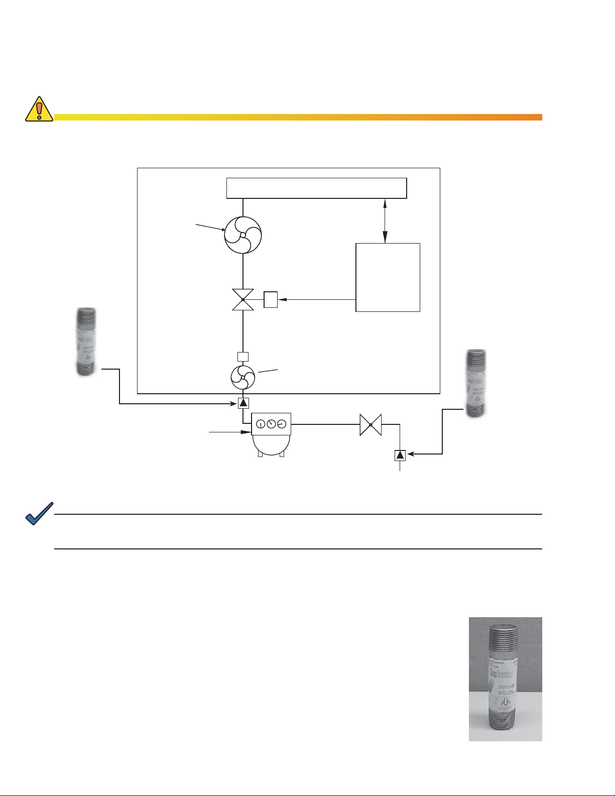
1.3 Natural Gas System Block Diagram
CAUTION!
Do not include the generator system as part of a local gas piping system test. Damage to the
generator pre-regulator may result. The generator system is pressure tested in accordance with
NFPA standards prior to shipment.
ENGINE
Demand
Low-pressure
Regulator
CONTROLS
APU
Enclosure
Flare Coupling
(Quick-Disconnect)
Low pressure excess
flow valve (optional)
NOTE: 1 psi = 28" WC
0.5 psi (min.)
1 psi (nominal)
10 psi (max)
14" WC
(max.)
Solenoid
S
Engine must have
7" to 11" WC and 156 cubic
feet/Hr. to operate
Pre-Regulator
Maxitrol 325-3
10 psi max input
Meter
WC = Water Column H
CONTROL
Manual
Shutoff
O
2
High pressure
(optional)
excess flow valve
Fig. 1-5, Arrangement of Metered, Nominal Pressure (1-2psi) Natural Gas System
NOTE:
For added safety, a low pressure and high pressure excess fl ow valve may be installed.
ATTENTION:
Federal DOT Regulation 49 CFR Part 192.383, Excess Flow Valve Customer Notifi cation, requires gas
utilities to either voluntarily install Excess Flow Valves (EFVs) on all new home service lines or to notify
builders about EFVs’ benefi ts and availability. EFVs are installed on gas service lines during pre-construction
site work, and automatically activate when a gas line is ruptured. Excess fl ow valves should never be used as
in-line regulators. They cannot perform this function and may damage equipment.
16
Fig. 1-6, Excess Flow Valve
(above ground ¾" x 4" NPT nipple)
Alpha P/N 042-146-10
042-288-B0-001, Rev. A
1.0 System Overview, continued
1.4 Liquid Propane System Block Diagram
LP PROPANE - VAPOR WITHDRAWAL
DEMAND
LOW PRESSURE
REGULATOR
APU
ENCLOSURE
SENSOR
8oz
MAX
11"WC
BLOCK DIAGRAM
ENGINE
SOLENOI
S
LOW FUEL ALM
LOW FUEL
PRESSURE
SWITCH
CONTROLS
D
CONTROL
11"W
OUTLE
C
T
PROPANE
POST-REG
PROPANE
ENCLOSURE
LPG TANK
Fig. 1-7, LP Propane Vapor Withdrawal Block Diagram
042-288-B0-001, Rev. A
17

1.0 System Overview, continued
1.5 Specifi cations
Model CE-3x2 5.0kW
DC Output Voltage: -51.5 to -52V @ no load -51.5 to -52V @ no load
DC Output Load Regulation: 0.5V 0.5V
Output Current: 52V @96A max. 52V @ 144A max.
PN-6x-T 7.5kW
Noise
Voiceband: <54dBrnc <54dBrnc
Wideband: <100mVrms in any 3kHz bandwidth from 10k to 20mHz <100mVrms in any 3kHz bandwidth from 10k to 20mHz
Broadband: <250mVp-p from 20 to 100mHz <250mVp-p from 20 to 100mHz
Engine: 398cc, air-cooled, single OHV
RPM (Variable Speed): 2800 to 3600RPM 2100 to 3450RPM
10.5hp (using natural gas fuel)
624cc, air-cooled, twin OHV
13.1hp (using natural gas fuel)
Acoustic Noise
dBA 10' @ 100% rated load: 68.5 avg. 70.3 avg.
dBA 20' @ 100% rated load: 62.5 avg. 64.3 avg.
dBA 10' @ 70% rated load: 66.9 avg. 66.4 avg.
dBA 20' @ 70% rated load: 60.9 avg. 60.4 avg.
System Size: CE-3x PN-6x
Height (in/cm): 44/111.8 36/99.1
Width (in/cm): 26/66 39.25/99.7
Depth (in/cm): 24/61 24/61
Weight (lb/kg): 395/179.2 338/153.3
Fuel Consumption
Natural Gas: 1000BTU/ft
Propane Gas: 2520 BTU/ft
Gas Inlet Pressure: 0.5 to 2 PSI Inlet pressure
Ignition Charger Voltage: 13.5Vdc 13.5Vdc
Ignition Charger Current: 6A max. 6A max
Remote Interface Length: 50ft. max
Agency Compliance: UL2200, NFPA 37/54/58 and 70, CSA 22.2, FCC Class A UL2200, NFPA 37/54/58 and 70, CSA 22.2, FCC Class A
3
3
80ft3/hr 156ft3/hr
1.1gal/hr 1.48gal/hr
3
/hr 54ft3/hr
40ft
4.62lb/hr 6.24lb/hr
(Please contact Alpha Technologies for low pressure)
Distance depends upon proper installation, de-rating,
and wire gauge. Please contact Alpha Technologies for
remote interface length usage.
0.5 to 2 PSI Inlet pressure
(Please contact Alpha Technologies for low pressure)
25ft. max
Distance depends upon proper installation, de-rating, and
wire gauge. Please contact Alpha Technologies for remote
interface length usage.
Common to All Models
Fuel System, Controls & Monitoring: The controls and fuel system meet applicable sections of NFPA 37, 54, and 58 for automatic unattended operation of
Sensors: Gas hazard, pad shear, water intrusion & tamper
Safety shutdowns: Low oil pressure
remotely located generators. Full system control and status monitoring included
Water intrusion
Pad shear
Gas hazard (propane or Natural Gas)
Over speed
Over crank
Over temp
Low fuel pressure shutdown (Propane only
Optional Features
Optional Integrated Propane
Storage: (5kW APU only)
For locations where gas is not available, Alpha offers the CE-G propane enclosure for use with the 5kW APU system.
Contact local propane supplier for proper tank sizing. Fully CSA & NFPA compliant, and designed for curbside
applications.
18
)
042-288-B0-001, Rev. A

1.0 System Overview, continued
1.5 Specifi cations, continued
Engine Specifi cations, PN-6x-T 7.5kW
Manufacturer: Kohler
Make/model: CH20
Cycle: 4
Compression Ratio: 8:5:1
Displacement, cu. in. (cc): 38 (624)
Rated Horsepower:
(using natural gas fuel)
Engine Speed (rpm): 2100-3450
Bore, in. (mm): 3.08 (77)
Stroke, in. (mm): 2.64 (67)
Valve Train: Overhead valve
Valve Material:
Intake
Exhaust
Number of Cylinders: 2
Cylinder Block Material: Aluminum with cast iron liners
Cylinder Head Material: Aluminum
Cylinder Head Tightening Torque,
ft. lb (Nm):
Piston Rings: 2 compression, 1 oil
Crankshaft Material: Heat treated, ductile iron casting
Bearings:
Number
Type
Governor: Electronic
Starter Motor: Electric, 12Vdc, solenoid shift
Lubrication System: Full pressure
Oil Capacity:
(with fi lter and cooler), qt. (L) 2 (1.9 )
Oil Filter Tightening Torque 1/2 turn
Oil Pressure, psi (kPa): 25-35 (172-241)
Low Oil Pressure, psi (kPa): 3.5±1.5 (24.1±13.8)
Fuel Type: Natural gas or propane
Fuel Pressure, kPA (in. water): 7-11 (1.7-2.7)
Battery Voltage: 12Vdc
Battery Ground: Negative
Battery Recommendation (min.): 585 CCA @ 0ºF ( -18ºC)
Spark Plug Type:
(Kohler P/N 24 132 02-S)
Spark Plug Gap, in. (mm): 0.030 (0.75)
Spark Plug Tightening Torque, ft.
lb (Nm):
Ignition System: Capacitive discharge
Cooling System: Air cooled
High Engine Temperature, ºF (ºC): 305 (152)
Exhaust System: USFS approved spark arrestor
13.1
Steel
®
Stellite
face
30 (41)
2
Replaceable sleeve
(Champion RC12YC)
18-22 (24.4-29.8)
48Vdc Generator Set Specifi cation
Manufacturer: Kohler
Dimensions (in/mm): 21.5"L x 20"W x 21.8"H
Weight (lb/kg): 190/86
Rated* kW: 7.5
Rated Voltage:
(after rectifi er)
Rated Amps: 144 @ 52Vdc
Stator Resistance:
(ohms)
Stator Type: 3-phase, 3-lead,
Excitation Method: Permanent magnet,
Coupling Type: Direct-to-Engine
Insulation (stator): Class 180,
Winding Material: Copper
* Derate approximately 4% per 1000 ft (300m)
over 500 ft (153m) above sea level. Derate 1%
for each 10ºF (5.5ºC) increase in temperature
above 77ºF (25ºC).
546 x 508 x 554
52 ± 0.5Vdc @ no load
0.024
ungrounded
brushless
epoxy varnish,
vacuum-impregnated
042-288-B0-001, Rev. A
19

1.0 System Overview, continued
1.5 Specifi cations, continued
Engine Specifi cations, CE-3x2 5K-T
Manufacturer: Kohler
Make/model: CV14
Cycle: 4
Compression Ratio: 8:5:1
Displacement, cu. in. (cc): 24.3 (398)
Rated Horsepower:
(using natural gas fuel)
Engine Speed (rpm): 2800-3600
Bore, in. (mm): 3.43 (87)
Stroke, in. (mm): 2.64 (67)
Valve Train: Overhead valve
Valve Material:
Intake
Exhaust
Number of Cylinders: 1
Cylinder Block Material: Aluminum with cast iron liners
Cylinder Head Material: Aluminum
Piston Rings: number/type: 2 compression, 1 oil
Crankshaft Material: Heat treated, ductile iron casting
Bearings:
Number
Type
Governor: Electronic
Starter Motor: Electric, solenoid shift
Lubrication System: Full pressure
Oil Capacity:
(with fi lter and cooler), qt. (L) 2.1 (2.0)
Oil Type: summer/winter: Synthetic 5W-30
Oil Pressure, psi (kPa): 25-35 (172-241)
Low Oil Pressure, psi (kPa): 2-5 (13.8-34.5)
Fuel Type: Natural gas or propane
Fuel Pressure, kPA (in. water): 7-11 (1.7-2.7)
Battery Voltage: 12Vdc
Battery Ground: Negative
Battery Recommendation (min.): 425 CCA @ 0ºF ( -18ºC)
Spark Plug Type: Kohler P/N 24 132 03
Spark Plug Gap, in. (mm): 0.75 (0.030)
Spark Plug Tightening Torque, ft.
lb (Nm):
Ignition System: Battery/Coil
Cooling System: Integrated air cooled
High Engine Temperature, ºF (ºC): 305 (152)
10.5
Steel
®
Stellite
face
2
Replaceable sleeve
18-22 (24.4-29.8)
48Vdc Generator Set Specifi cation
Manufacturer: Kohler
Dimensions (in/mm): 24"L x 26"W x 44"H
Weight (lb/kg): 395/179
Rated* kW: 5kW
Rated Voltage:
(after rectifi er)
Rated Amps: 96 @ 52Vdc
Stator Resistance:
(ohms):
Stator Type: 3-phase, 3-lead,
Excitation Method: Permanent magnet,
Coupling Type: Direct-to-Engine
Insulation (stator): Class 155,
Winding Material: Copper
* Derate approximately 4% per 1000 ft (300m)
over 500 ft (153m) above sea level. Derate 1%
for each 10ºF (5.5ºC) increase in temperature
above 77ºF (25ºC).
546 x 508 x 554
52 ± 0.5Vdc @ no load
0.024
ungrounded
brushless
epoxy varnish,
vacuum-impregnated
20
042-288-B0-001, Rev. A

2.0 Site Preparation
2.1 Site Considerations
• Where possible, select a site away from houses, and above the 100-year fl ood plain.
• Place in a shaded location to minimize the effects of solar loading.
• Avoid locating the enclosure where it obstructs or inhibits visibility.
• Locate the enclosure away from sprinkler systems, or other sources of forced water.
• Locate the enclosure out of the prevailing wind to minimize the buildup of snow or windborne dust.
• Determine if soil conditions are suitable for the appropriate grounding system.
• Verify utility power cabling is terminated at the site.
• Ensure maintenance access and exhaust clearance.
• Locate the enclosure to allow for 36" of clearance around all enclosure door and exhaust
openings.
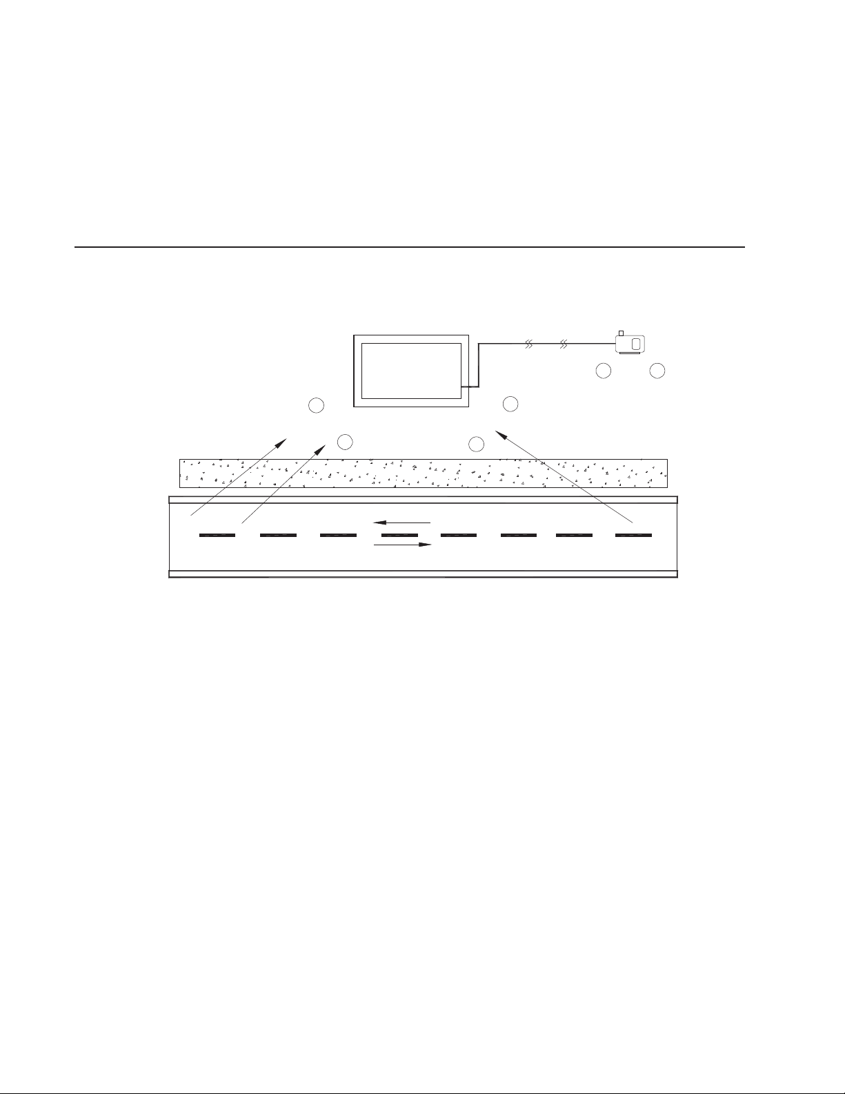
2.2 Acoustics
Nuisance noise is of concern to nearby residents. Nuisance noise is a directional noise
which can cause discomfort during engine-generator operation to nearby residential
occupants (audible levels may vary due to absorption and refl ection caused by the immediate
surroundings).
Audible impact on neighborhoods is mitigated by recent advances in muffl ers, fl ame resistant
sound materials, intake air sound attenuators, along with improved cabinet airfl ow dynamics.
The fi gures below show the measured audible levels from CE-3x2 5KW and PN-6x-T 7.5kW
generators at full load. Note the symmetry of these emissions. Deployment decisions must
include noise consideration to minimize nuisance noise.
North West
72.8dBA
West
71.9dBA
10'
South West
70.1BA
042-288-B0-001, Rev. A
North
73.0dBA
North East
Exhaus
Intake
71.4dB
t
A
East
70.0dBA
5'
South East
70.5dBA
South
72.4dBA
CE-3x2 PN-6x-T
Fig. 2-1, Generator Sound Levels at 100% Load
dB a
56. 3
64. 3
70. 3
20'
10'
50'
Feet
21
2.0 Site Preparation, continued
2.2 Acoustics, continued
20 Feet, (64 dBa)
50 Feet (56 dBa)
Fig. 2-2, Acoustical Measurements in Relation to Placement Near Residences
(generator sound levels at full load)
22
042-288-B0-001, Rev. A
2.0 Site Preparation, continued
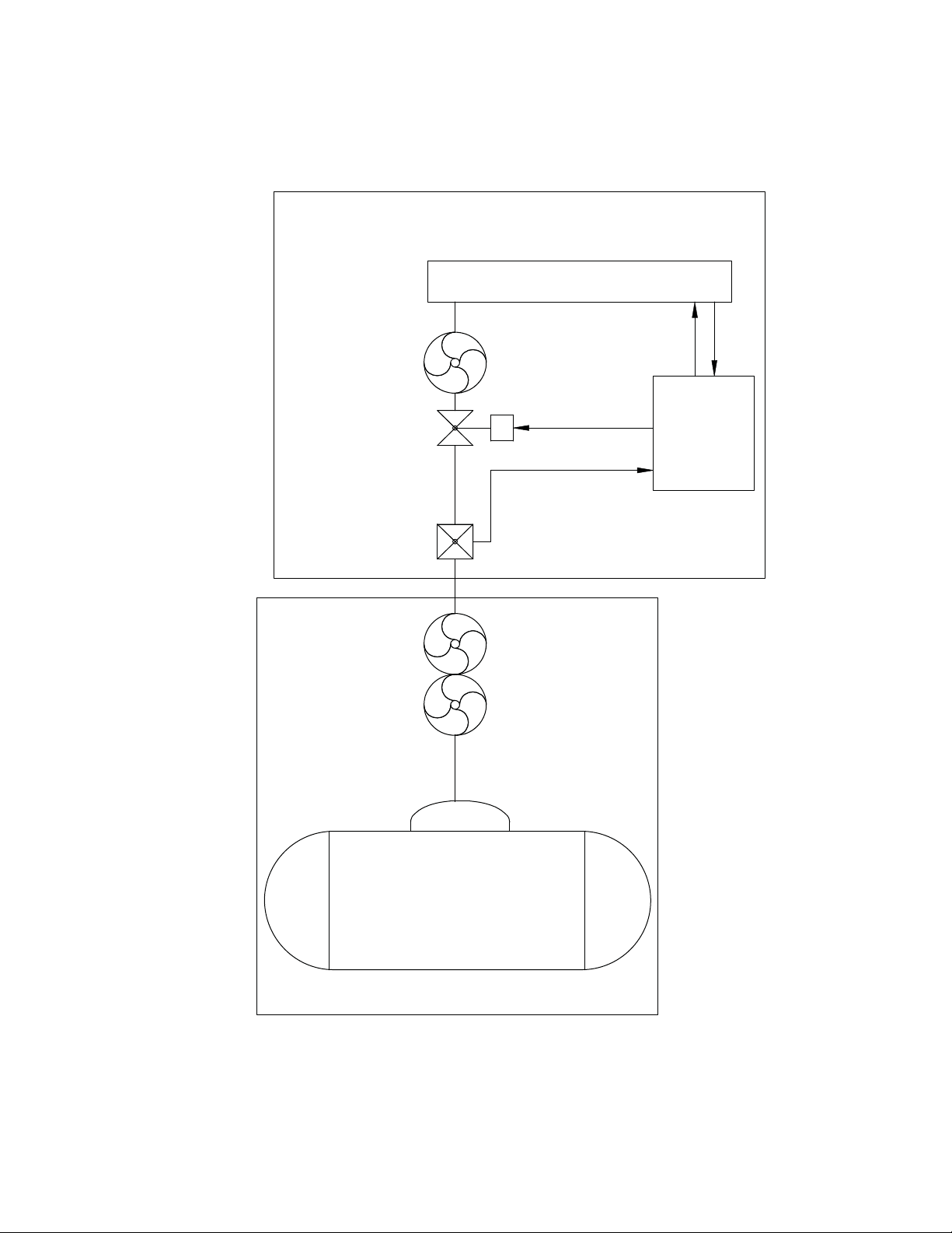
2.3 Enclosure Impact Protection
The National Fire Protection Agency (NFPA) requires that equipment using natural gas
or liquid propane be protected, based on good engineering practices, in areas where
vehicle traffi c is normally expected at that location. The required protection is based on the
anticipated speed of the vehicles operated in that area. The NFPA does not provide specifi c
guidelines for when protection is needed or the nature of the protection. However, the intent is
to provide suffi cient protection for the equipment should contact occur by a vehicle operating
in the area at a reasonably expected speed.
Alpha Technologies, Inc. cannot anticipate all the ways a vehicle may potentially threaten an
installed generator system, or the specifi c type of protection that is appropriate for a particular
location. The determination of the threat to the equipment and the means of protection are
the responsibility of the end user of the equipment and the authority having local jurisdiction.
The following installation drawings are general recommendations and are not intended to
be specifi c guidelines for protecting the equipment. The numbers of bollard posts (or other
protection devices) depend upon equipment locations, site surveys, and traffi c patterns as
shown below in a typical installation.
Generator Protection, Vehicular Areas
Several variations of installation are possible. The diagrams provide information on the
different confi gurations and site installations. The collocated natural gas meter shown below
may require two to four bollard posts depending on location, site surveys, and traffi c patterns.
Typical bollard post construction may change based on local codes regarding pipe material,
concrete, or stanchion design.
042-288-B0-001, Rev. A
Generator
Fig. 2-3, Vehicular Area Impact Protection for Collocated Natural Gas Meter
23
2.0 Site Preparation, continued
2.3 Enclosure Impact Protection, continued
Generator Protection, Vehicular Areas, continued
The remote located natural gas meter shown below may require two to four bollard posts
depending on location, site survey, and traffi c pattern. This is a typical installation design with
gas meters supported by dual risers and located near the cabinet.
ATTENTION:
Install enclosure protection in compliance with local codes.
Generator
Fig. 2-4, Vehicular Area Impact Protection for Remote Natural Gas Meter
24
042-288-B0-001, Rev. A
2.0 Site Preparation, continued
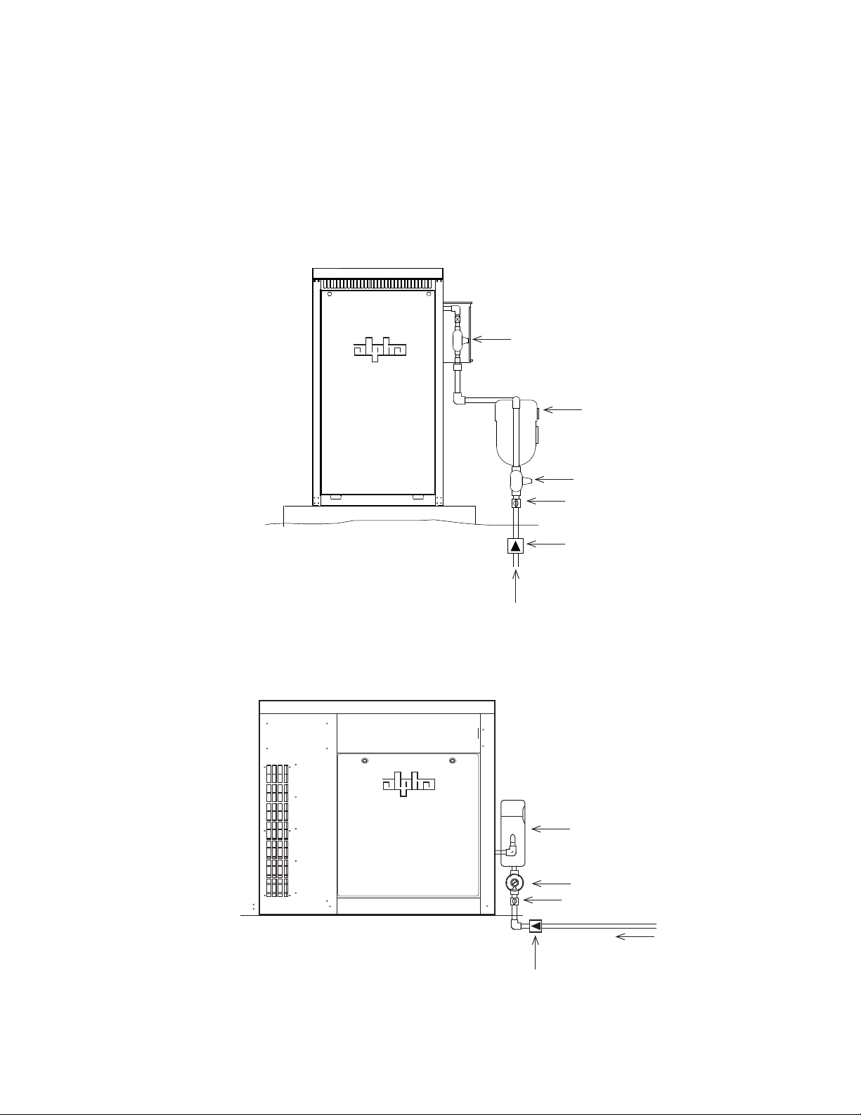
2.4 Natural Gas Meter Confi gurations
The gas utility company should have the meter installed prior to generator arrival. Meter
confi gurations must comply with local codes. The illustrations provided are for illustrative
purposes only.
Gas Utility Box
Natural Gas Meter
Street Regulator
Manual Shutoff
Excess Flow Valve
(optional)
Street Pressure
Fig. 2-5, Collocated Natural Gas Meter Setup for CE-3x2 Generator
Natural Gas Meter
Street Regulator
Manual Shutoff
Excess Flow Valve
(optional)
Street Pressure
042-288-B0-001, Rev. A
Fig. 2-6, Collocated Natural Gas Meter Setup for PN-6x-T 7.5kW System
25
2.0 Site Preparation, continued
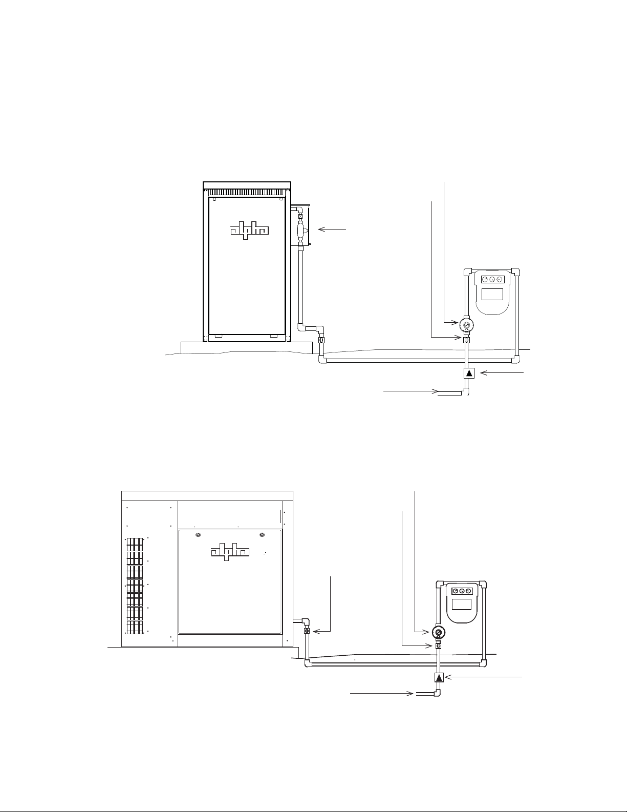
2.4 Natural Gas Meter Confi gurations, continued
The gas utility company should have the meter installed prior to generator arrival. Meter
confi gurations must comply with local codes. Examplesz provided are for illustrative purposes
only.
Street Regulator
Manual Shutoff
Gas Utility Box
Natural Gas Meter
Street Pressure
Fig. 2-7, Collocated CE-3x2 5K-T Generator with Remote Natural Gas Meter
Street Regulator
Manual Shutoff
Manual
shutoff required if
meter cannot be
seen
Natural Gas Meter
Excess Flow Valve
(optional)
26
Excess Flow Valve
Street Pressure
(optional)
Fig. 2-8, Remote Natural Gas Meter Setup for PN-6x-T 7.5kW Generator
042-288-B0-001, Rev. A
2.0 Site Preparation, continued
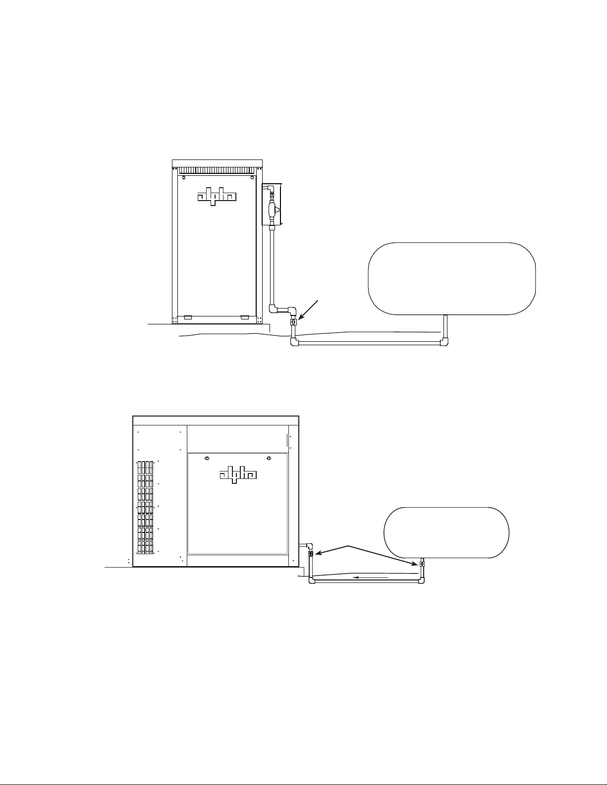
2.5 Liquid Propane Systems
For systems using liquid propane, the end user must provide a suitable LP tank. For
collocated propane enclosures, see the CE-G Series Enclosure Installation Manual, Alpha
P/N 031-093-C0-001, located at www.alpha.com.
Manual
Shutoff
Fig. 2-9, Liquid Propane Setup, CE-3x2 5K-T
Manual
Shutoff
Location
User-provided LP Tank
User-provided LP Tank
042-288-B0-001, Rev. A
(Most Common)
Fig. 2-10, Liquid Propane Setup, PN-6x-T 7.5kW
27

2.0 Site Preparation, continued
2.6 Grounding Requirements, CE-3x2 5K-T
The ground rod system is typically used in remote applications where the generator is located
away from the power supply enclosure and exposed to lightning strikes, or coincidental
surges. The wiring interface between the DC Genset and system carries a system ground to
ensure common ground between both cabinets and communication devices. The remote APU
cabinet ground rod serves only as an alternate discharge path.
NOTE:
Alpha Technologies recommends using the grounding method illustrated below. The grounding method for a particular site will be
dependant upon soil type, available space, local codes, NEC (National Electric Code), and other site- specifi c characteristics.
Alpha Technologies recommends 5 ohms minimum ground resistance between enclosure and ground rods, in accordance with IEEE
1100-1999 Powering and Grounding Electronic Equipment. NEC minimum grounding standard is 25 ohms.
Alpha Technologies assumes no responsibility or liability for failure of the installer to comply with the requirements of all applicable local
and national codes. Where allowed, exothermic welding may be used as an alternative to Burndy clamps and connectors.
6
7
5
8
4
3
1
2
Fig. 2-11, Enclosure Grounding, CE-3x2 5K-T
Service grounding (required). #6AWG Copper wire from
1
service entrance ground bar.
2
Two ground rods, 6' apart
10
(for reference only)
Burndy YGHP58C2W-3 or equivalent compression ground
6
tap connector
Terminate at ground bar
7
9
28
Lightning protection (optional). 1/2" x 8' Copper ground
3
rods, 4 places.
4
Burndy YGHP58C2W-3 or equivalent compression ground
tap connector
5
#6 bare copper wire from loop to enclosure ground bar
Terminate at ground bar
8
#6 bare copper loop terminated at each ground rod, 30” below
9
grade (min). Corrosion-proof (25 yr. life-span) connections
suitable for direct burial MUST be used
10
#2 AWG wire
042-288-B0-001, Rev. A
2.0 Site Preparation, continued
2.7 Grounding Requirements, PN-6xT 7.5kW
The ground rod system is typically used in remote applications where the generator is located
away from the power supply enclosure and exposed to lightning strikes, or coincidental
surges. The wiring interface between the DC Genset and system carries a system ground to
ensure common ground between both cabinets and communication devices. The remote APU
cabinet ground rod serves only as an alternate discharge path.
A
B
Conduit
AC In
DC Out
Ground
A
B
042-288-B0-001, Rev. A
• 8 feet long, 1/2 inch diameter copper electrode.
• To aid in serviceability, place the ground electrode outside the concrete pad’s perimeter. Consult
local utility codes for additional cabinet grounding and utility requirements.
• #6AWG bare copper wire exposed 5 feet above grade (min.) for output ground bus bar.
• Clamp #6AWG bare copper wire exposed 5 feet above grade (min.) for output ground bus bar.
Front of Enclosure
Fig. 2-12, Enclosure Grounding, PN-6x-T 7.5kW
29

3.0 Installation
Front of Pad
38.00
.63
00
19.50 SYMM
.
41
17
S
MMY
C
L
C
L
2.25
8
6
.
2
9.25 REF
1
.
056
FER
3
1
2
3.1 Installing the CE-3x2 5K-T or PN-6x-T 7.5kW Pad Template
To ease the installation of the generator enclosure, use the pad mounting template to
accurately locate the mounting holes for the generator cabinet mounting hardware. The
installation instructions for the two types of generator pad templates are the same, only the
dimensions vary.
Site Considerations:
• Where possible, select a site that is above the 100-year fl ood plain, and away from
houses.
• Place in a shaded location to minimize the effects of solar loading.
• Avoid locating the enclosure where it will be an obstruction or inhibit visibility.
• Locate the enclosure away from sprinkler systems or other sources of forced water.
• Locate the enclosure out of the prevailing wind to minimize the buildup of snow or the
accumulation of wind-borne dust.
• Determine if soil conditions are suitable for the installation of the required grounding
system.
• Verify utility power cabling has been run and terminated at the site.
Template frame
1
Threaded fasteners with “hex” spacers (4).
Insert mounting bolts into the threaded
2
fasteners to prevent concrete from fouling the
threads. Once the pad has cured, attach the
enclosure to the threaded fasteners.
Sweep compression plate. For the CE3x2, verify sweep is held in place against
3
the frame by the compression plate. For
the PN-6xT, verify the sweep retaining
bracket is located properly.
30
Fig.3-1, Pad Frame Template for CE-3x2 5K-T
(in inches)
042-288-B0-001, Rev. A

3.0 Installation, continued
3.1 Installing the CE-3x2 5K-T or PN-6x-T 7.5kW Pad Template, continued
1. Determine the size of the pad you need. Typically it is best to leave at least 6 inches
of space between the outside of the cabinet and the edge of the pad. Occasionally,
you might want to extend the pad in one or more directions for ease of access during
maintenance.
2. Using the physical placement of the mounting bolts in the pad template, calculate the
exact dimensions of the pad, taking into consideration the size of the wooden frame used
around its perimeter. Measure the overall pad dimensions from the inside of the wooden
frame.
3. Using the dimensions calculated in step 2, excavate the site for the pad.
WOODEN FRAME
FRAME TEMPLATE
Fig. 3-2, Pad frame and mounting template CE-3x2 5.0 kW
NOTE:
If using a gravel foundation, the hole for the pad must be deep enough to place the gravel before installing the
pad template. Check local codes for exact specifi cations.
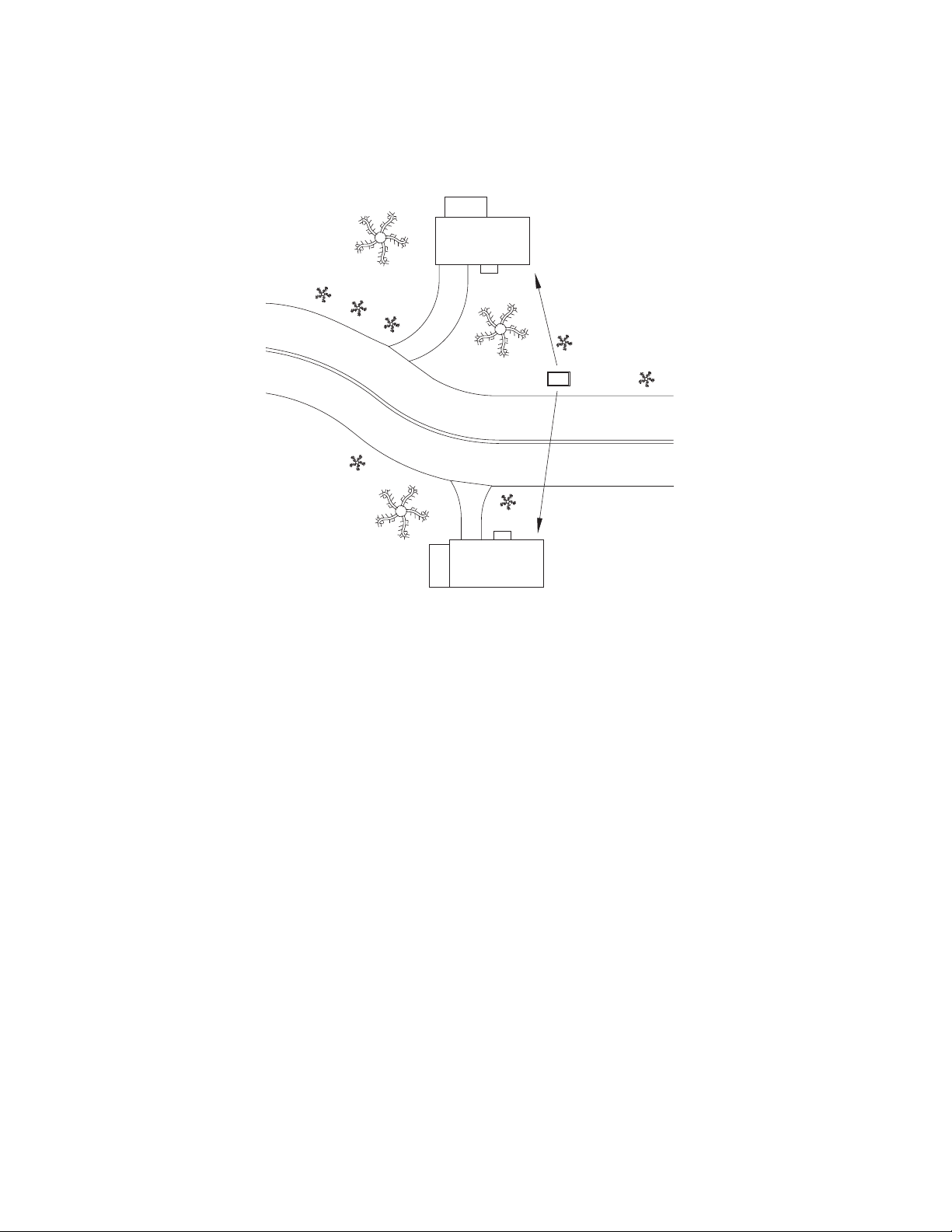
4. Dig the trenches for the sweep conduits. Consult your local codes for the required depth,
fi ll material, and back fi lling.
042-288-B0-001, Rev. A
5. Install the wooden perimeter frame in pad opening.
6. Verify that the top of the pad is 4 inches above grade to minimize debris buildup around
the base of the cabinet.
7. Place the pad template in pad opening and adjust the template so the tops of the four
threaded fasteners are level with the top of the wooden frame.
8. Plug the threaded inserts.
9. Pour the concrete, smooth the surface of the pad, and let the concrete cure.
10. Backfi ll the sweep trench.
31

3.0 Installation, continued
3.1 Installing the CE-3x2 5K-T or PN-6x-T 7.5kW Pad Template, continued
Backfi ll trenches over conduit.
A
Concrete pad.
B
Stagger or nest conduits for passage through the
C
three inch pad sweep opening on CE-3x2.
When pouring the pad the sweeps may extend to a
D
maximum of 4 inches above the fi nished pad to pre-
vent concrete from fi lling the sweep openings. After
the concrete is set, trim the conduit to a height no
more than 2 inches above the surface of the pad.
Max. height = 2.00"
B
C
A
D
Fig. 3-3, Cross-section of Sweep Trench
32
042-288-B0-001, Rev. A

3.0 Installation, continued
3.2 Installation, CE-3x2 5K-T
Prior to installation verify the following:
• All necessary grounding rods and materials are in place.
• Utility power was run to site in accordance with the NESC (National Electric Safety
Code).
• Obtained local safety practices for working with high-voltage systems.
• Gas piping, hardware, supports, and other gas carrying components to the pad location
conform to NFPA standard and local requirements.
Required Tools and Materials:
• Crane to lift enclosure from shipping pallet and place on pad
• Key(s) to enclosure doors
• Digital voltmeter
• Torque wrench with insulated handle and 7/16" socket
• 7/16” box-end wrench
• NO-OX or other suitable corrosion inhibiting agent (NCP-2)
• Silicone sealant GE RTV123 (or equivalent)
• Phillips screwdriver (for pad shear mounting)
• 5/8" socket for removing pallet mounting bolts
• Hard hats
• Utility knife
WARNING!
To prevent injury or death, do not walk, or allow personnel to walk, beneath the suspended
unit. Use steel-toe work shoe protection. Use hard hats at all times during this procedure.
Before lifting, verify the transport path is clear of obstructions.
042-288-B0-001, Rev. A
33

3.0 Installation, continued
3.2 CE-3x2 5K-T Installation
3.2.1 CE-3x2 5K-T Transportation and Lifting
The generator weighs approximately 395 lbs. A safe means of transporting to the site,
and unloading the generator must be arranged. Do not transport, lift, or place the
generator on a surface unable to fully support its weight.
The generator is shipped bolted to a pallet. Remove the protective outer wrapping
material, and inspect the outside of the generator for shipping damage. Use a
forklift to place the unit (still bolted to its pallet) in the back of the transport vehicle
for delivery to the installation site. Once on-site, follow the procedure outlined on
the following pages to lift the enclosure from the shipping pallet and place it on the
concrete pad.
CAUTION!
Do not install the ignition battery until the enclosure is set in place in its permanent location.
34
Fig. 3-4, Pad Bolt Location, CE-3x2 5K-T
042-288-B0-001, Rev. A

3.0 Installation, continued
3.2 CE-3x2 5K-T Installation, continued
3.2.1 CE-3x2 5K-T Transportation and Lifting, continued
The enclosure is lifted via the attached lifting ears. The lifting ears are attached to the
cabinet with 1/4-20 x 3/8” stainless steel SAE J429 Grade 8 hex head bolts, torqued
80 to 90 in-lbs.
1
1/4-20 x 3/8” stainless steel
A1
SAE J429 Grade 8 hex head bolts.
4 places per ear.
1
A1
1
B1
042-288-B0-001, Rev. A
1
B1
Bolts torqued 80 to 90 in-lbs.
Fig. 3-5, Lifting Ear Attachment
35

3.0 Installation, continued
3.2 CE-3x2 5K-T Installation, continued
3.2.2 Enclosure Installation, CE-3x2 5K-T
1. Lift the enclosure with a lifting appararatus rated in excess of 500 lbs. Confi gure
the lifting arrangement so the distance from the top of the cabinet to the lift ring
or hook is at least twice the distance between the lifting ears (Fig. 3-2).
2. Position the enclosure above the concrete pad, and slowly lower it into position
over the pad’s 3/8" (or 1/2") anchor or J-bolts. Use a 25-year vapor barrier
between the concrete and enclosure base to inhibit moisture ingress, and to
prevent possible corrosion caused by metal to concrete contact. The vapor
barrier material (such as 30 lb. felt, neoprene pond liner, or heavy grade tar
paper) should initially extend at least 6" in all directions around the perimeter of
the enclosure. After the enclosure is in place, the material should be cut closer to
the enclosure, using the appropriate knife or cutting tool.
3. Secure the enclosure using stainless or galvanized fl at washers, lock washers,
and 3/8" (or 1/2") nuts at each mounting bolt. Torque mounting hardware in
accordance with the manufacturer's recommendation.
4. Make a small cutout in the vapor barrier material directly under the pad shear
sensor, Apply silicone glue to the concrete pad (in the cutout section) and set the
pad shear magnet into the glue (potted side down). Let the glue set 12-24 hours.
CAUTION!
To prevent damage to the enclosure, it must be mounted fl ush to a completely fl at surface. If the
concrete pad is uneven or has bumps, cracks or other imperfections, the installer is responsible for
correcting these defects prior to installing the enclosure.
2D
1
D
2
3
Fig. 3-6, Enclosure with Lifting Ears Installed, CE-3x2 5K-T
36
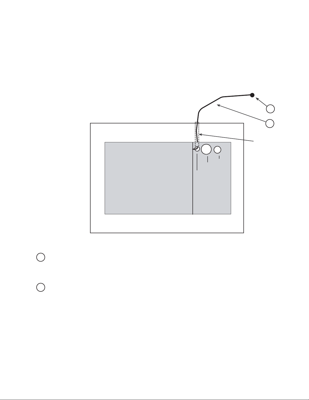
Fig. 3-7, Water Intrusion Alarm (1), Pad Shear Sensor (2),
and Pad Shear Magnet (3)
042-288-B0-001, Rev. A

3.0 Installation, continued
3.3 PN-6x-T 7.5kW Installation
Prior to installation verify the following:
• All necessary grounding rods and materials are in place.
• Utility power run to site in accordance with the NESC (National Electric Safety Code).
• Obtained local safety practices for working with high-voltage systems.
• Gas piping, hardware, supports, and other gas carrying components to the pad location
conform to NFPA standard and local requirements.
Required Tools and Materials:
• Crane to lift enclosure from shipping pallet and place on pad
• Key(s) to enclosure doors
• Digital voltmeter
• Torque wrench with insulated handle and 1/2" socket
• 1/2" box-end wrench
• NO-OX or other suitable corrosion inhibiting agent (NCP-2)
• Silicone sealant GE RTV123 (or equivalent)
• Phillips screwdriver (for pad shear mounting)
• 5/8" socket for removing pallet mounting bolts
• Hard hats
MOUNTING STUD POSITIONO 0.625 x 1.000 4 PL
• Utility knife
O
1.375AC SWEEP
O
3.000DC SWEEP
O
0.875GROUND SWEEP
042-288-B0-001, Rev. A
ENCLOSURE
FRONT
7.60
Fig. 3-8, PN-6x-T 7.5kW Sweep Dimensions (in inches)
26.00
0.581
0.25
3.00
3.40
5.35
5.60
37

3.0 Installation, continued
3.3 PN-6x-T 7.5kW Installation, continued
3.3.1 PN-6x-T 7.5kW Transportation and Lifting,
The enclosure as shipped contains the Auxiliary Power Unit (APU) and weighs
approximately 338 lbs. A safe means of transporting to the site, and unloading the
enclosure must be considered. Do not transport, lift, or place the unit on any surface
unable to fully support its weight.
The system is shipped bolted to a pallet. Once the system arrives, remove the
protective outer wrapping material and inspect the outside of the enclosure for
shipping damage. Use a forklift to place the unit (still bolted to its pallet) in the back of
the transport vehicle for delivery to the installation site. Once on site, attach the lifting
plates to the enclosure at the holes indicated below. Remove the front and rear doors
and remove the pallet mounting bolts using a 5/8" socket wrench.
CAUTION!
Do not install the ignition battery until the enclosure is placed in its permanent location.
Pallet Mounting Bolt
(hidden)
Lifting Plate
Mounting Holes
Pallet Mounting Bolt
(hidden)
Lifting Plate
Mounting Holes
Fig. 3-9, Pallet Bolt Locations, PN-6x-T 7.5kW
38
042-288-B0-001, Rev. A

3.0 Installation, continued
3.3 PN-6x-T 7.5kW Installation, continued
3.3.1 PN-6x-T 7.5kW Transportation and Lifting, continued
The enclosure is lifted via four lifting plates included with the generator. The lifting
plates are attached to the cabinet with 1/4-20 x 3/8" stainless steel SAE J429 Grade
8 hex-head bolts, torqued 80 to 90 in-lbs.
WARNING!
To prevent injury or death, do not walk, or allow personnel to walk, beneath the suspended
unit. Use steel-toe work shoe protection. Use hard hats at all times during this procedure.
Before lifting, verify the transport path is clear of obstructions.
Spreader Bar
Front View Side View
Fig. 3-10, Enclosure with Lifting Ears Installed, PN-6x-T 7.5kW
042-288-B0-001, Rev. A
39

3.0 Installation, continued
3.3 PN-6x-T 7.5kW Installation, continued
3.3.2 Enclosure Installation Procedure, PN-6x-T 7.5kW
1. Position the enclosure above the concrete pad and slowly lower it into position
over the pad’s 3/8" (or 1/2") anchor or J-bolts. A 25+ year vapor barrier MUST be
used between the concrete and enclosure base to inhibit moisture ingress, and
to prevent possible corrosion caused by metal to concrete contact. The vapor
barrier material (such as Alpha P/N 564-721-10) should initially extend at least
1/2" in all directions around the perimeter of the enclosure. After the enclosure is
in place, the material should be cut closer to the enclosure, using the appropriate
knife or cutting tool.
2. Secure the enclosure using customer-supplied stainless, galvanized (or better),
fl at washers, lock washers and 3/8" (or 1/2") nuts at each mounting bolt. Torque
mounting hardware in accordance with manufacturers’ ratings.
3. The pad shear sensor is located in the left hand corner of the enclosure from the
rear door. To install, locate the loose magnet (located in a plastic bag included
with the enclosure). Remove the two screws holding the sensor in place, and lift
out. Using a silicone based glue, glue the loose magnet to the pad in the center
of the hole. After the glue has set, install the sensor with the two Phillips screws
so it faces the glued down magnet.
If a pedestal is used, relocate the pad shear sensor to the L-bracket located near
the bottom of the pedestal. Glue the pad shear magnet directly below the sensor.
Use the extender cable to connect the pad shear sensor wires to the wires
located in the generator enclosure (route wires through pad shear sensor hole in
the fl oor of the generator enclosure).
CAUTION!
To prevent damage to the enclosure, it must be mounted fl ush to a completely fl at surface. If the
concrete pad is uneven or has bumps, cracks or other imperfections, the installer is responsible for
correcting these defects prior to installing the enclosure.
0.581
ENCLOSURE
FRONT
0.25
3.00
3.40
5.35
5.60
Fig. 3-11, Installation Location of Pad Shear/
Magnet Assembly
(Dimensions in inches)
WARNING!
The pad shear sensor is a safety feature that must be correctly installed before connecting
the gas utility. This is a CRITICAL safety feature required to disable the generator in the
event of automobile impact, seismic, or other unforeseen catastrophic event.
40
042-288-B0-001, Rev. A

3.0 Installation, continued
3.4 Enclosure Grounding, CE-3x2 5K-T
Run the chassis and earth grounding wires through the one-inch opening in the bottom of
the generator enclosure. Using a 7/16" nutdriver or socket, secure the ground leads to the
grounding stud located on the enclosure wall. See Fig. 3-12 below.
ATTENTION:
It is the responsibilty of the system installer to verify applicable grounding requirements, and to ensure that
system grounding complies with all state, local, or regional requirements.
042-288-B0-001, Rev. A
Fig. 3-12, Enclosure Grounding, CE-3x2 5K-T
41

3.0 Installation, continued
3.5 Enclosure Grounding, PN-6x-T 7.5kW
Run the chassis and earth grounding wires through the one-inch opening in the bottom of
the generator enclosure. Using a 7/16" nutdriver or socket, secure the ground leads to the
grounding stud located on the enclosure wall. See Fig. 3-13 below.
ATTENTION:
It is the responsibilty of the system installer to verify applicable grounding requirements, and to ensure that
system grounding complies with all state, local, or regional requirements.
Ground Stud
Fig. 3-13, Enclosure Grounding, PN-6x-T 7.5kW
1" Opening
3" Opening
42
042-288-B0-001, Rev. A

3.0 Installation, continued
3.6 Natural Gas Utility Fuel Hookup, CE-3x2 5K-T
These general instructions apply to either remote or collocated systems.
• Connection to the utility fuel line is made using a 3/4" shear point union, 1/2" black iron
pipe, and the appropriate pipe thread sealant suitable for use with natural gas or propane
vapor.
• Use approved pipe thread sealant on all fuel line connections (except fl are fi ttings).
• Thoroughly check the fuel system for vapor leaks. Use an approved leak detector liquid,
or a soap-water solution, with the fuel system pressurized to the cabinet with 0.5 to 1.0
pounds of fuel pressure. Do not use test solutions that contain ammonia or chlorine,
since they prevent soap from bubbling.
• Check and satisfy all local codes before connecting gas to the fuel system.
WARNING!
Observe all safety precautions when working with fuel lines. The illustrations on this page
should be considered for general reference only. Installation should ONLY be done by
qualifi ed personnel. Alpha is not liable for gas leaks resulting from improper installation.
042-288-B0-001, Rev. A
Fig. 3-14, Utility Gas Service Input, CE-3x2 5K-T
43

3.0 Installation, continued
3.7 Natural Gas Utility Fuel Hookup, PN-6x-T 7.5kW
These general instructions apply to either remote or collocated systems.
• Connection to the utility fuel line is made using a 3/4" shear point union, 1/2" black iron
pipe, and the appropriate pipe thread sealant suitable for use with natural gas or propane
vapor.
• Use approved pipe thread sealant on all fuel line connections (except fl are fi ttings).
• Thoroughly check the fuel system for vapor leaks. Use an approved leak detector liquid,
or a soap-water solution, with the fuel system pressurized to the cabinet with 0.5 to 1.0
pounds of fuel pressure. Do not use test solutions that contain ammonia or chlorine,
since they prevent soap from bubbling.
• Check and satisfy all local codes before connecting gas to the fuel system.
WARNING!
Observe all safety precautions when working with fuel lines. The illustrations on this page
should be considered for general reference only. Installation should ONLY be done by
qualifi ed personnel. Alpha is not liable for gas leaks resulting from improper installation.
Natural Gas Utility Fuel Connection
MANUAL SHUTOFF
REQUIRED IF METER
CANNOT BE SEEN
STREET REGULATOR
MANUAL SHUTOFF
METERED SUPPLY
STREET PRESSURE
NATURAL
GAS
METER
High pressure
excess flow valve
44
Fig. 3-15, Utility Gas Service Input, PN-6x-T 7.5kW
042-288-B0-001, Rev. A

3.0 Installation, continued
3.8 Liquid Propane Utility Fuel Hookup, CE-3x2 5K-T
For collocated propane enclosures, see the CE-G Series Enclosure Installation Manual,
Alpha P/N 031-093-C0-001, located at www.alpha.com.
• Connection to the LP fuel line is made using a 3/4" shear point union, 1/2" black iron pipe,
and the appropriate pipe thread sealant suitable for use with propane vapor.
• Approved pipe thread sealant must be used on all fuel line connections (except fl are
fi ttings).
• Thoroughly check the fuel system for vapor leaks. Use an approved leak detector liquid,
or a soap-water solution, with the fuel system pressurized to the cabinet with 0.5 to 1.0
pounds of fuel pressure. Do not use test solutions that contain ammonia or chlorine,
since they prevent soap from bubbling.
• Check and satisfy all local codes before connecting gas to the fuel system.
WARNING!
Observe all safety precautions when working with fuel lines. The illustrations on this page
should be considered for general reference only. Installation should ONLY be done by
qualifi ed personnel. Alpha is not liable for gas leaks resulting from improper installation.
042-288-B0-001, Rev. A
Manual
Shutoff
User-provided LP Tank
Fig. 3-16, Propane Fuel Hookup, CE-3x2 5K-T
45

3.0 Installation, continued
3.9 Liquid Propane Utility Fuel Hookup, PN-6x-T 7.5kW
• Connection to the LP fuel line is made using a 3/4" shear point union, 1/2" black iron pipe,
and the appropriate pipe thread sealant suitable for use with propane vapor.
• Approved pipe thread sealant must be used on all fuel line connections (except fl are
fi ttings).
• Thoroughly check the fuel system for vapor leaks. Use an approved leak detector liquid,
or a soap-water solution, with the fuel system pressurized to the cabinet with 0.5 to 1.0
pounds of fuel pressure. Do not use test solutions that contain ammonia or chlorine,
since they prevent soap from bubbling.
• Check and satisfy all local codes before connecting gas to the fuel system.
WARNING!
Observe all safety precautions when working with fuel lines. The illustrations on this page
should be considered for general reference only. Installation should ONLY be done by
qualifi ed personnel. Alpha is not liable for gas leaks resulting from improper installation.
46
Manual
Shutoff
User-provided LP Tank
Fig. 3-17, Propane Fuel Hookup, PN-6x-T 7.5kW
042-288-B0-001, Rev. A

3.0 Installation, continued
3.10 Making the DC Output Connection, CE-3x2 5K-T
Verify proper polarity with a digital voltmeter, and connect the Load to the DC output
connector.
Fig, 3-18, DC Output, CE-3x2 5K-T
042-288-B0-001, Rev. A
47

3.0 Installation, continued
3.11 Making the DC Output Connection, PN-6x-T 7.5kW
1. Locate and remove the safety shroud. The shroud is held in place with two thumb screws.
Shroud Location
2. Strip the user-supplied DC load wires 3/4". Loosen the 3/16" Allen screws and insert the
DC load wires. Torque to 120 in-lbs and replace the safety shroud.
Fig. 3-19, DC Output Safety Shroud
Positive DC Load Connection
Fig. 3-20, DC Output Connections, PN-6x-T 7.5kW
NOTE:
Before connection, read polarity with a multimeter. To connect a -48V customer load, make the negative load
connection to the postive terminal on the output terminal block, and make the positive load connection to the
negative terminal on the output terminal block.
Negative DC Load Connection
48
042-288-B0-001, Rev. A

3.0 Installation, continued
3.12 Connecting the Ignition Battery, CE-3x2 5K-T
WARNING!
For further information regarding the safe handling of batteries, refer to the Battery Safety
Notes at the beginning of this manual.
1. Set the RAS switch on the ECM to the STOP position.
2. Using a voltmeter, check ignition battery voltage. Battery voltage should be at least
12.5Vdc. If low, recharge before placing into operation.
3. Coat the battery terminals with battery corrosion preventative compound (NCP-2).
4 Connect the positive (red) battery terminals and torque to 60 in-lbs.
5. Connect the negative (black) battery terminals and torque to 60 in-lbs.
6. Secure the battery hold-down bracket.
7. To remove the battery, reverse procedure.
CAUTION!
To reduce the risk of arcing, disconnect the negative cable fi rst when removing the ignition battery
from the enclosure.
042-288-B0-001, Rev. A
49

3.0 Installation, continued
3.13 Connecting the Ignition Battery, PN-6x-T 7.5kW
The ignition battery is calcium/silver chemistry, 585 CCA , group 55 battery (Alpha P/N 181076-10).
WARNING!
For further information regarding the safe handling of batteries, refer to the Battery Safety
Notes at the beginning of this manual.
1. Set the RAS switch on the ECM to the STOP position.
2. Using a voltmeter, check ignition battery voltage. Battery voltage should be at least
12.5Vdc. If low, recharge before placing into operation.
3. Place the battery onto the pan located to the left of the generator, with the POS terminal
closest to the sweep opening.
4. Coat the battery terminals with battery corrosion preventative compound (NCP-2).
5 Connect the positive (red) battery terminals and torque to 60 in-lbs.
6. Connect the negative (black) battery terminals and torque to 60 in-lbs.
7. Secure the battery hold-down bracket.
8. To remove the battery, reverse procedure.
CAUTION!
To reduce the risk of arcing, disconnect the negative cable fi rst when removing the ignition battery
from the enclosure.
50
042-288-B0-001, Rev. A

3.0 Installation, continued
3.14 Terminal Block 2 (AC Line) Connections, CE-3x2 5K-T
Terminal Block 2 is above the ignition battery, located in the rear of the enclosure. Connect
the user-supplied wiring using a #1 fl at-head screwdriver. Strip wires 3/8" (9.5mm) and torque
to 7 in-lbs (0.8 Nm). Refer to the table and photo below for alarm defi nitions.
Fig. 3-21, Terminal Block 2 (TB2) Position 1, 5kW
Position 1
Terminal Block 2
Pos # Function
23 Major Alarm NC
22 Major Alarm NO
21 Major Alarm Com
20 See Note
19 Alarm Bypass Com
18 Alarm Bypass NO
17 Alarm Bypass NC
16 Eng Run Com
15 Eng Run Com NO
14 Eng Run Com NC
13 Minor Alarm NO
12 See Note
11 Minor Alarm COM NO
10 Door NO
9 Door COM
8 LPG Monitor PWR (-12V)
7 LPG Monitor PWR (+12V)
6 AC Line Fail NC
5 AC Line Fail NO
4 AC Line Fail COM
3 AC Input Ground
2 AC Input Neutral
1 AC Input Line
NOTE:
For customers requiring a Normally Closed (NC) logic minor alarm, make connections to TB2 positions 12
and 20.
042-288-B0-001, Rev. A
Table 3-1, Terminal Block 2 (TB2) Connections, CE-3x2 5K-T
51

3.0 Installation, continued
3.15 Terminal Block 2 (AC Line) Connections, PN-6x-T 7.5kW
Terminal Block 2 is located on the bulkhead next to the convenience outlet. Connect the usersupplied wiring using a #1 fl at-head screwdriver. Strip wires 3/8" (9.5mm) and torque to 7
in-lbs (0.8 Nm). Refer to the table and photo below for alarm defi nitions.
Terminal Block 2
Position 1
Fig. 3-22, Terminal Block 2 (TB2), PN-6x-T7.5kW
Terminal Block 2
Pos # Function
23 Major Alarm NC
22 Major Alarm NO
21 Major Alarm Com
20 See Note
19 Alarm Bypass Com
18 Alarm Bypass NO
17 Alarm Bypass NC
16 Eng Run Com
15 Eng Run Com NO
14 Eng Run Com NC
13 Minor Alarm NO
12 See Note
11 Minor Alarm COM NO
10 Door NO
9 Door COM
8 LPG Monitor PWR (-12V)
7 LPG Monitor PWR (+12V)
6 AC Line Fail NC
5 AC Line Fail NO
4 AC Line Fail COM
3 AC Input Ground
2 AC Input Neutral
1 AC Input Line
Table 3-2, Terminal Block 2 (TB2) Connections, PN-6x-T 7.5kW
NOTE:
For customers requiring a Normally Closed (NC) logic minor alarm, make connections to TB2 positions 12
and 20.
52
042-288-B0-001, Rev. A

3.0 Installation, continued
3.16 Final Inspection Checklist
CAUTION!
Set the ECM Run/Auto/Stop (RAS) switch to the STOP position before initially powering up the
ECM. This allows the operator to manually control the START and STOP functions of the APU until
the system is set up. This also prevents the APU from starting unexpectedly.
Once the installation is complete, verify the following:
1. Engine oil at proper level
2. All electrical connections securely made
3. Engine Control Module (ECM) set to STOP
4. Battery connections made
5. Battery voltage normal.
6. Gas connections checked for leak integrity
7. Gas pressure normal
When the above checks are complete, the unit is ready for initial turn-up.
042-288-B0-001, Rev. A
53

4.0 The Engine Control Module
The Engine Control Module (ECM) controls and monitors the generator’s Auxiliary Power Unit (APU).
The ECM is a two part assembly made up of the ECM Printed Circuit Board (ECM PCB) and the
Generator Remote Interface (GRI) board. The GRI is attached to the ECM PCB with three ribbon
cables.
The ECM provides interface connectors for the enclosure sensors, engine controller, battery sense,
line sense, and other equipment. The ECM monitors AC line and DC bus status to determine when
to start and stop the APU. In the event of an extended power outage or low DC bus voltage, the ECM
starts the APU to prevent the backup batteries from discharging to a level that could compromise the
ability of the system to provide a continuous, reliable source of power.
The ECM monitors the entire system for abnormal operating conditions such as low engine oil
pressure, engine over-temperature, gas leaks, enclosure pad shear, etc. If certain abnormal
conditions or alarms are present, the ECM prevents the generator from starting or shuts it down
immediately. This provides public safety, and prevents damage to the APU.
The ECM provides an interface between the APU and Alpha communication devices. The ECM
controls and monitors the APU. Status information and alarms can be read from the front panel LEDs,
or by four “Form C” relay contacts. The ECM is capable of reporting 9 major alarms, 8 minor alarms,
and 2 notifi cations.
ECM
ECM
CE-3x2 5K-T PN-6x-T 7.5kW
Fig. 4-1, Location of Engine Control Module (ECM)
54
042-288-B0-001, Rev. A

4.0 The Engine Control Module, continued
ECM PCB LED Indicators and Switches
1 Communications Input (J4)
(Pin #1 at bottom of connector)
2 Major Alarm Indicator (Red LED)
3 Minor Alarm Indicator (Red LED)
4 Notify Indicator (Orange LED)
5 Comm Indicator (Green LED)
6 System Indicator (Green LED)
7 Run-Auto-Stop (RAS) Switch
8 Service/Reset Push Button Switch (SW3)
9 Transponder Interface (J6)
(Pin #1 at top of connector)
10 Enclosure Alarm Input Connector (J10)
11 Fuel Enclosure Alarm Connector (J5)
12 Interface Input Connector from APU (J4)
13 Inverter Battery String Connector (J8)
14 Battery Charger Control Interface
15 AC Generator Voltage, Current Connector (J7)
16 AC Line Input Connector (J6)
(Connected at all times)
Pin 1
Pin 1
1
10
2
3
4
5
11
6
7
12
8
13
14
15
9
16
10
11
12
13
14
15
16
Fig. 4-2 (a), ECM LED Indicators, Switches, and Interface Connections
GRI
J 2
J 3
J 1
J 2
J 1
J 3
ECM PCB
1
Pin 1
2
3
4
5
6
7
8
Pin 1
9
042-288-B0-001, Rev. A
Fig. 4-2 (b), ECM Printed Circuit Boards
55

4.0 The Engine Control Module, continued
4.1 Theory of Operation
Under normal operating conditions (no alarms) the ECM Run-Auto-Stop (RAS) switch is in
the AUTO (center) position. The ECM has control of the APU while in the Auto mode. When
the RAS switch is switched from the STOP position to the AUTO position the ECM will run the
APU for a one minute self-test after a short delay. This indicates the ECM is in the Auto mode
and is capable of starting and stopping the APU automatically.
The APU can be controlled manually by placing the RAS switch in the RUN (up) position or
the STOP (down) position. In Auto mode, the ECM continuously monitors the AC line voltage,
DC bus voltage, enclosure sensors, and APU status. If a fault occurs, the ECM determines
whether to start or inhibit the APU based on the type of failure.
4.1.1 Standby Operating Condition Less Than Three Minutes
If an AC line disturbance or outage lasts less than three minutes, the ECM will not
start the APU, unless the battery bus voltage drops below the default threshold (Low
DC Bus Level) of 49V. The ECM indicates line failure locally using the front panel
LEDs (see Fig. 4-2a), and remotely by the appropriate Terminal block 2 terminal positions (see Fig. 3-21 and 3-22.
4.1.2 Standby Operating Condition More Than Three Minutes
If an AC line disturbance or outage lasts more than three minutes, the ECM start
delay timer expires, and the ECM attempts to start the APU. The ECM will attempt
to start the engine 9 times with either a 30 second or a 60 second pause between
attempts (See Table 4-1). If the engine fails to start, the ECM reports an Engine
Over-crank alarm. Otherwise, the ECM starts and runs the APU until either a normal
shutdown, or major alarm, occurs.
Crank Cycle
Crank Attempt
Crank Duration
Pause (no crank)
12345 678 9
15 Sec
30 Sec
15 Sec
30 Sec 30 Sec 30 Sec 30 Sec 30 Sec60 Sec60 Sec
15 Sec
15 Sec
15 Sec
15 Sec
15 Sec
15 Sec 15 Sec
Table 4-1, Engine Crank Cycle
Engine
Over-crank
Alarm
56
042-288-B0-001, Rev. A

4.0 The Engine Control Module, continued
4.1 Theory of Operation, continued
4.1.3 Normal APU Shutdown
The ECM initiates a normal APU shutdown when the AC line is within normal limits,
the DC bus alarm is not active, the 12 minute cool-down period has elapsed, and the
Engine Run command is not active. If started due to low DC Bus voltage, the ECM
continues to run the APU until specifi c conditions are met (see below) or a major
alarm occurs. The APU will run until the DC voltage of approximately 53V is obtained
and then the 12 minute cool-down period has elapsed.
4.1.4 Abnormal APU Shutdown
The ECM immediately shuts down the APU under the following conditions:
• Major alarm
• Activation of manual engine stop switch
• Receipt of software engine stop command
• General generator failure
4.2 ECM Operating Mode Summary
The ECM monitors the status of the AC line and DC bus to make a determination when to
start and stop the generator. The ECM also monitors APU status while the engine is running
and immediately shuts down the unit if certain alarm conditions are detected. The ECM
reports status information via a parallel data interface and/or an Alphabus serial data (RS-
485) interface.
The following conditions can cause the ECM to start the generator:
1. Loss of AC line for a period of time in excess of Start Delay (programmable).
2. DC bus voltage drops below Low DC bus voltage (default, 49V).
3. Manual run switch is activated.
4. Software run command is received.
5. A self-test is initiated manually.
6. An automatic self-test is initiated.
The following conditions are required for normal engine shutdown:
1. AC line is qualifi ed.
2. DC bus voltage is greater than 49Vdc (if the unit is started due to low DC bus voltage, DC
bus voltage must reach >53V).
042-288-B0-001, Rev. A
3. Cool-down period has expired.
4. Engine Run command is not active.
57

4.0 The Engine Control Module, continued
4.2 ECM Operating Mode Summary, continued
The following conditions cause immediate engine shutdown:
1. Manual engine stop switch is activated.
2. Software engine stop switch is received.
3. Any of the following engine alarms become active:
• Low oil
• Engine over-temperature
• Low fuel
• Over-speed
• Over-crank
• Over-voltage
4. Any of the following system alarms become active:
• Gas hazard
• Pad shear
• Water intrusion
• General APU failure
4.3 LED Indicators
The ECM uses fi ve LEDs to display alarms and system status.
The red Major alarm LED indicates failure of a critical component, or some other situation
(i.e. pad shear) where the system has gone off-line or system failure/shutdown is imminent.
The engine is shuts down immediately during major alarms. Most major alarms are latched
(will not self-clear) by the ECM. A site check by service personnel is required to repair the
fault and clear the system.
The red Minor alarm LED indicates a system fault which, although not indicative of imminent
system failure, requires service attention before the condition worsens. A site check by
service personnel is recommended.
The amber Notify LED represents status information that is not signifi cant enough to be
classifi ed as an alarm. At present, only two items fi t into this category: AC Line Status and
Engine Service Required.
The green COMM (Communications) LED illuminates for two seconds after each
communications session on the Alphabus. This is standard with Alphabus communications
systems.
The green SYS (System) LED indicates that the microprocessor has power and is operating
normally. This LED normally fl ashes once a second. When the ECM is in factory test mode,
the LED fl ashes twice a second.
58
042-288-B0-001, Rev. A

4.0 The Engine Control Module, continued
4.4 Control Functions
The Run-Auto-Stop (RAS) switch controls the Auxiliary Power Unit (APU). Typically the RAS
switch is in the AUTO position so the ECM has control of the generator. When the RAS is
not in the AUTO position a minor alarm is displayed. The STOP position is used to stop or
prevent APU operation during maintenance. Placing the RAS switch in the STOP position
for three (3) seconds, then switching back to AUTO will clear any latched alarms and
start the generator (if the cause of the alarm has been corrected). The RUN position will
start and run the engine until the switch is released to AUTO. The engine may not shut down
immediately after the switch is returned to the AUTO position because shutdown criteria must
fi rst be met. Placing the RAS switch in the AUTO position from the STOP position will start
and run the APU for one minute, after a short delay.
The Service Reset switch resets the engine service timer and displays all active alarms.
The ECM’s programmable service interval defaults to 100 hours. When 100 hours of engine
runtime elapses, a Service Required notifi cation is sent and the notifi cation LED illuminates.
After the engine has been serviced, pressing and holding the service reset switch for
fi ve seconds resets the 100-hour service counter. All of the LEDs fl ash while the switch
is depressed. The LEDs then remain on solid until the switch is released. This provides
feedback to the technician, indicating the effective resetting of the engine service counter.
The Service Reset button also displays alarm information. To retrieve details about an active
alarm, press and release the Service Reset button. Active alarms (major and minor) are
indicated by the LED display (See Fig. 4-3). Press the button again to display the next active
alarm. Pressing the button when there are no more active alarms will reset the LEDs to their
normal state. Several quick fl ashes of all fi ve LEDs indicates the end of the alarm list. If the
Service Reset button is not depressed again after an alarm is indicated, the LEDs return to
their normal display after 30 seconds. Resetting alarms using status monitoring or the manual
stop switch also clears the alarm pattern indicated by the LEDs.
NOTE:
Depressing the Service Reset button for fi ve seconds causes the service timer to clear, possibly disrupting the
preventive maintenance schedule.
Major Alarm LED (Red)
Minor Alarm LED (Red)
Notify LED (Amber)
COMM LED (Green)
SYS LED (Green)
RAS Switch
Service Reset Switch
042-288-B0-001, Rev. A
Fig. 4-3, LED Indicators and Control Functions
59

4.0 The Engine Control Module, continued
4.5 Alarm Classifi cations
Major Alarms:
A major alarm indicates a critical failure or situation that causes the system to go off-line.
Major alarms cause the engine to shutdown immediately and generally prevent further
operation. Most major alarms are latched by the ECM. Placing the RAS switch to the STOP
position for three seconds, then switching back to AUTO clears any latched alarms and
starts the generator (if the cause of the alarm has been corrected). A site check by service
personnel is required to repair the fault and clear the system.
• Low Oil Pressure (Latching): Engine oil pressure is below safe limits. APU operation is
suspended. The alarm is cleared when the Reset command is issued or when the manual
stop switch is activated.
• Engine Over-temp (Non-latching): Engine temperature has exceeded safe limits. APU
operation is suspended. The alarm is reset when the engine temperature falls within safe
limits.
• Engine Over-speed (Latching): Engine rpm has exceeded safe limits. APU operation is
suspended. The alarm is cleared when the Reset command is issued or when the manual
stop switch is activated.
• Engine Over-crank (Latching): Engine failed to start. The alarm is cleared when the
Reset command is issued or when the manual stop switch is activated.
• Alternator Over-voltage (Latching): The generator set has detected the alternator
output voltage is too high. Depending on generator type, this likely means that the
voltage regulator or engine speed governor has failed. Operation of the unit has been
suspended. The alarm is cleared when the Reset command is issued or when the manual
stop switch is activated.
The alternator over-voltage alarm can be triggered in three ways:
1.) The generator controller can signal the ECM that an over-voltage condition exists.
2.) A programmable threshold of 57V (Hi DC Bus Level) is exceeded for fi ve seconds
(programmable for a range of 5-15 seconds; fi ve seconds is the default value).
3.) A fi xed threshold of 2.5V/cell (60V for a 48V system) is exceeded for fi ve seconds.
• Gas Hazard (Latching): The concentration of hydrocarbon fuel in the power system’s
enclosure air space has exceeded safe limits or 10%-20% of the Lower Explosive
Limit (LEL) for more than three (3) seconds. APU operation is suspended. The alarm is
cleared when the Reset command is issued or when the manual stop switch is activated.
• Water Intrusion (Non-latching): Water level within the main or fuel enclosure has
exceeded safe limits. APU operation is suspended while the alarm is active. The alarm is
cleared and the engine will re-start when the water level falls below maximum limits.
• Pad Shear (Latching): The main or fuel enclosure has shifted from its pad mounting
position. APU operation is suspended. The alarm is reset when the unit is returned to its
original position and the Reset command is issued or the manual stop switch is activated.
The APU will not start if the pad shear magnet is not correctly installed below the pad
shear sensor.
• Low Fuel Pressure (Latching – after fi ve activations): Site fuel supply (propane-fueled
APU only) is insuffi cient for extended engine operation. The alarm is reset fi ve minutes
after the fuel supply is replenished.
60
042-288-B0-001, Rev. A

4.0 The Engine Control Module, continued
4.5 Alarm Classifi cations, continued
Minor Alarms:
Minor alarms indicate a system fault which, though not indicative of imminent system failure
or shutdown, requires service attention before the condition worsens. A site check by service
personnel is recommended.
• Control Fail (Latching – after fi ve activations): A control failure between the ECM and
the generator set. Typically this means the engine did not start or stop when commanded
to do so. The alarm is cleared when the Reset command is issued or the manual stop
switch is activated.
• Alternator Off (Non-latching): This alarm is active if the generator controller has
disabled the alternator output. A generator controller may disable the alternator output if
the output voltage cannot be held above some threshold.
• Self-test Fail (Latching): Activates when the most recent generator self-test fails. The
alarm is cleared when the Reset command is issued, the manual stop switch is activated
or another Self-Test command is issued.
• Low Ignition Battery: The generator’s ignition battery voltage has fallen below 11.5Vdc.
Alarm is cleared when battery voltage rises above 12Vdc indicating battery recovery has
begun. The low ignition battery voltage does not trigger an alarm during engine cranking.
• Auto Mode Disabled: The position of the ECM control select switch. When the Run-
Auto-Stop (RAS) switch is in a manual (STOP or RUN) position, the ECM has no control
over engine operation and therefore raises an alarm. This is a hardware ‘lockout’ input
and cannot be changed via status monitoring.
• Tamper: One of the enclosure doors is open. The alarm clears when the door is closed
(disabled).
• DC Bus Fault: The power system DC bus voltage, as measured at the ECM, is less
than the DC bus voltage (programmable - default = 49V). This alarm clears automatically
when the bus voltage exceeds 2V above nominal (i.e., 50Vdc in a 48V system). Note the
alarm clears, but the generator starts when DC bus level drops to 49Vdc or lower.
• Engine Disabled: Command to disable normal operation of the generator set. When set
to DISABLE the engine is shutdown under all conditions. A Minor Alarm indicator is active
if this switch is set to DISABLE. The engine is disabled by software after fi ve consecutive
Low Fuel alarms, or fi ve consecutive Control Fail alarms. This alarm is cleared by issuing
a “Reset” command or when the “Manual Stop” switch is activated.
• Output Circuit Breaker OFF or Disabled (PN-6x-T Only): No ECM indication. Verify
circuit breaker position visually.
042-288-B0-001, Rev. A
Notifi cations:
Notifi cations represent important information not urgent enough to be considered an alarm.
There are currently two notifi cations.
• Line Failure: The ECM’s determination of the state of AC line voltage. Loss of AC utility
input is one of the criteria for starting the generator.
• Service Required: Routine maintenance of the engine/generator is due. This alarm
activates when the Service Countdown reaches 0. It is cleared by depressing the service
timer reset button for fi ve seconds (Refer to Section 7.0, System Maintenance, for further
information).
61

4.0 The Engine Control Module, continued
4.6 ECM Alarm Overview
Alarms are indicated in three ways: ECM LEDs, RS-485 communications, and alarm
contact closures on the ECM transponder interface. Alarm indications on the ECM LEDs are
displayed by pressing the service reset button momentarily. Pressing the service reset switch
again will reveal the next alarm in the list. When the alarm list has been exhausted, all LEDs
will fl ash several times and then return to their normal functions. Placing the RAS switch to
the STOP position for three (3) seconds, then switching back to AUTO will clear any
latched alarms and start the generator if the cause of the alarm has been corrected.
The following table shows the LED patterns and the alarms they represent.
Major Alarms
Abbreviation
Major
Minor
Notify
Comm
System
Major Alarms
Abbreviation
Major
Minor
Notify
Comm
System
Red
Amber
Green
123456789
LO OT OS OC GH WI PS LPOV
10 11 12 13 14 15 16 17 18
CF AO TF IB TP DC ED LFAD
19
SR
62
1. (LO)* Low Oil Pressure
2. (OT) Engine Over-temp
3. (OS)* Engine Over-speed
4. (OC)* Engine Over-crank
5.
6. (GH)* Gas Hazard
7. (WI) Water Intrusion
8. (PS)* Pad Shear
9. (LP)*** Low Fuel Pressure
(OV)* Alternator Over-voltage
10. (CF)*** Control Fail
11. (AO) Alternator OFF
12. (TF)* Self-Test Fail
13. (IB) Low Ignition Battery
14. (AD) Auto-mode Disabled
15. (TP) Tamper (Default, Disabled)
16. (DC) DC Bus fault
17. (ED) Engine Disable
18. (LF)** Line Failure
19. (SR)** Service Required
Legend: * = Latching Alarm
** = Notifi cations
*** = Alarm “latches” after 5 activations
Table 4-2, Major/Minor Alarm Indications and Notifi cations
(LEDs displayed on the ECM)
042-288-B0-001, Rev. A

4.0 The Engine Control Module, continued
4.7 Connecting the Alarm and Control Connections
Alarm output and communication connections are located on Terminal Block 1.
Pin Alarm Signal Description Alarm Active State
TB 1
Pin 1
10 Not used Not used
11 Not used Not used
12 Not used Not used
Terminal Block 1
1 Engine Run Common Common
2 Engine Run Closed with respect to Pin 1
3 Engine Run Open with respect to Pin 1
4 Major Alarm Common Common
5 Major Alarm Closed with respect to Pin 4
6 Major Alarm Open with respect to Pin 4
7 Minor Alarm Common Common
8 Minor Alarm Closed with respect to Pin 7
9 Minor Alarm Open with respect to Pin 7
Fig. 4-4, Terminal Block 1
042-288-B0-001, Rev. A
63

4.0 The Engine Control Module, continued
4.8 ECM DIP Switch and Fuse Confi guration
The ECM PCB has an eight-position DIP switch (SW5) used to confi gure the generator
interface, APU output voltage (AC or DC), and utility voltage.
The GRI board has three fuses, F1, F2, and F3.
F2: 12V Output to
APU Fan and Enclosure
Gas Detector
(2A, 250V Slo-Blo)
Alpha P/N 460-205-10
F1: 12V Input from APU
(2.5A, 250V Slo-Blo)
Alpha P/N 460-204-10
SW5
F3: 120/240Vac Input
to ECM Logic Transformer
(250mA, 250V Slo-Blo)
Alpha P/N 460-166-10
Low DC Bus Level Default 49V (2V/cell)
High DC Bus Level Default to 57V (2.38V/cell)
Service Interval Default 100 hours
Autotest Interval Will auto set to 14 days when SW5-8 is set ON
Autotest Duration Default 10 minutes
Start Delay Default 180 seconds (3 minutes)
Shutdown Delay Default 720 seconds (12 minutes)
Over-voltage Duration Default 5 seconds
GRI
Fig. 4-5, SW5 and Fuse Locations
Telecom Defaults
ECM PCB
64
Table 4-3, Telecom Defaults
042-288-B0-001, Rev. A

4.0 The Engine Control Module, continued
4.8 ECM DIP Switch and Fuse Confi guration, continued
ECM SW5 Settings Meaning
12 3456781 = ON, 0 = OFF
1 Standard Confi guration
0 0 0 Invalid output voltage confi guration
0 0 1 24Vdc Output
0 1 0 36Vdc Output
0 1 1 48Vdc Output
0 0 N/A
0 1 120Vac Input
1 1 240Vac Input
1 0 ECM drives starter with the
1 1 "Engine Start" signal becomes
"Engine Start" signal
"Engine Run" signal
0 Autotest OFF
1 Autotest sequence enabled with
14-day test interval
Table 4-4, DIP Switch Settings
NOTE:
Programming parameters that affect the Autotest feature via status monitoring will override this switch setting.
To reset factory defaults, turn all DIP switches off, power up the ECM (plug in AC line sense) for 10 seconds,
remove power, then reset DIP switches.
Input Voltage Confi guration
Output Voltage Confi guration
Interface
ON
Engine Start/Run Signal
Enable Autotest
042-288-B0-001, Rev. A
1
3
2
45 67 8
Fig. 4-6, SW5 Settings
65

4.0 The Engine Control Module, continued
4.9 ECM Interface Block Diagram and Connectors
The Generator Remote Interface provides power conditioning to the ECM PCB, and
connection between cabinet sensors and the APU control. The interface supplies all
necessary signals, alarms, logic power, and analog voltages required for telemetry at the
central offi ce or relevant monitoring station, and allows the ECM to start and stop the engine
alternator as part of the network controlled periodic test sequence.
ECM
Fuel Low
Pressur
e
Switch
(Propane Only
Pa d
)
Wate r
Intrusion
Hour
Meter
00 1
Shear
QUART Z
Tamper
5
Generator
Control Board
Inductor
Cap
Output
Rectifier
2
1
Pin 1
Battery heater mat
Ignition
Battery
PN-6X-T (48V) PI Filter
Ignition
BatteryCharger
Cap
Ignition
Battery
Output
AC
CB
Gen.
Control
Signal s
Engine/Alternator
Engine
Block
Heater
Carb
Heater
Fuel
Solenoid
Ga s
Detector
66
TB2
Pin 1
Fig. 4-7, ECM/APU Interconnection
Duplex
Outlet
NOT A
SERVICE
OUTLE
T
042-288-B0-001, Rev. A

4.0 The Engine Control Module, continued
4.10 ECM Self-test
Generator testing consists of starting and running the generator for a duration of 10 minutes.
Generator testing can be initiated two ways:
1. The ECM is confi gured to periodically run an automatic test.
2. A one-minute automatic test is performed when the manual control switch is returned to
Auto from Stop.
The ECM monitors all engine-related signals and will declare a self-test as failed if any of the
following alarms activate during the test:
• Low Oil Pressure
• Engine Over-temperature
• Engine Over-speed
• Engine Over-crank
• Low Fuel
• Alternator Over-voltage
• ECM Control Failure
• Alternator Not On
• Low Ignition Battery
• Low DC Bus Voltage
The ECM will not start a self-test if the engine is disabled, the stop switch is engaged, or the
engine is already running.
If the AC line fails during a test, the test will terminate normally, but the engine will continue to
run until line voltage returns. If the test fails because the DC Bus alarm activates, the test will
terminate. The Self-test Fail alarm becomes active and the generator runs until the DC Bus
alarm clears.
The Self-test Fail alarm may be cleared using a reset command, or by successfully running a
subsequent test.
042-288-B0-001, Rev. A
67

4.0 The Engine Control Module, continued
4.10 ECM Self-test, continued
The following programmable, internal ECM variables control automatic self-tests.
• Autotest Interval: The number of days between automatic tests.
• Autotest Countdown:
• Autotest Duration: Each Autotest is measured in minutes. The test duration is 10
minutes.
Manually Enabling the Autotest Feature:
Use SW5-8 to enable the Autotest feature with a 14-day test interval. The fi rst autotest begins
14 days from the time the ECM is powered up with the confi guration switch changed from 0 to
1 (OFF to ON). To disable the autotest sequence, put SW5-8 in the OFF position and restart
the ECM. On power up, the ECM looks for a change in the switch position before it changes
the test control parameters.
1. Go to the site on the day of the week and time of day you want the self-test to occur.
2. Disconnect and remove the ECM.
3. Turn OFF SW5-8.
4. Install and re-power the ECM briefl y (15 second minimum powerup time). If AC is
present, this can be done by connecting J6 (AC line, the 2-position mate-n-lock plug at
the bottom of the ECM). Disconnect and remove the ECM (again).
5. Turn ON SW5-8.
6. Reinstall the ECM with all connectors.
The self-test will occur 14 days from the time the ECM is powered.
4.11 Maintenance Functions
The ECM monitors time between periodic maintenance of the engine-generator. The service
interval is the number of hours of engine runtime between servicing. When the engine
runtime is equal to service interval, the ECM activates the Service Required notifi cation and
turns on the amber notifi cation LED. The default value of Service Interval is 100 hours, and
can be programmed from 0 to 250.
Service Due is the number of engine runtime hours before the next periodic maintenance is
required. Pressing and holding the Service Reset switch for fi ve seconds resets the service
counter and it is updated with the current value of the service interval.
68
042-288-B0-001, Rev. A

5.0 Turn-up and Test
5.1 Appearance and Condition of Components
Prior to applying power, open each door of the enclosure. Observe and note the condition of
the following:
• Doors and locking mechanisms
• Seals
• Door intrusion switches
5.2 System Preparation
The following procedure involves starting and stopping the engine using the Engine Control
Module (ECM). It assumes the engine is properly connected to the 12V ignition battery, and
the natural gas (or propane) fuel has been installed, pressurized, and tested for leaks. Before
beginning, verify the circuit breaker (located near the ECM) is in the ON position.
1. Ignition Battery Test Procedure:
A. Connect a digital voltmeter (DVM) set for DC Volts to the ignition battery
terminals. Connect the Red (+) lead to the positive terminal and the Black (-) lead
to the negative terminal.
B. The DVM should read at least 12Vdc (+ 2V). If this reading is lower than
specifi ed, recharge the batteries to 13.8Vdc before proceeding.
2. Check Engine Lubrication. Check the engine crankcase oil level. If necessary, add oil
to the FULL mark. DO NOT OVERFILL. Refer to the engine manufacturers’ operation
manual for proper fi ll capacities and oil types. Ensure that the same brand of oil is used
for topping the oil level (some oil manufacturer’s additives are not compatible with each
other). Never attempt to measure the oil level, or add oil, when the engine is in operation.
Placing the ECM in the Stop position disables the generator for maintenance.
WARNING!
• To prevent injury, never attempt to start a generator that has an active Leak Detect
alarm. Correct the alarm condition before starting the generator.
• Do not use batteries (AGM or Gell Electrolyte) that read below 9V. Batteries discharged
below a safe point can cause an explosion hazard by gassing during recharge.
• Do not attempt to crank or start the engine before servicing with the recommended oil,
or engine failure will result.
042-288-B0-001, Rev. A
69

5.0 Turn-up and Test, continued
5.3 Performing a Local APU Test
Procedure:
1. Locate the ECM and set the Run/Auto/Stop (RAS) switch to the STOP position.
2. Verify ignition battery and AC line sense connection to ECM.
3. Verify all alarms on ECM are OFF, except Tamper Alarm & Auto Mode Disabled.
4. Remove gas port plug from input side of demand regulator, install brass manometer port
connection fi tting and connect manometer to fi tting (see Section 7-9 for details).
5. Move the RAS switch from Stop to Auto.
6. Verify the engine starts within 9 crank cycles. If engine fails to start within 9 crank cycles
and Engine Over-crank is activated, the gas line needs to be purged by removing the
air fi lter and placing your hand over the carburetor throat and cranking the engine until it
starts.
7. Verify 11" of water column pressure is present at the input of the demand regulator.
8. If necessary, adjust the pre-regulator or dual regulator (located on gas bottle assembly for
propane) by removing regulator cap and adjusting for 11" ± 1" of water column pressure.
Perform under NO-LOAD condition (see Section 7.9 for details).
9. Set RAS switch to Stop.
10. Remove brass manometer fi tting and reinstall plug to demand regulator input monitoring
port using approved pipe sealant.
11. Check demand regulator input monitoring port for leaks.
12. Set RAS to Auto.
NOTE:
The Generator Control Board master switch will override the Run/Auto/Stop (RAS) switch on the ECM. This
switch defaults to the center (ECM) position.
Generator Set
Run/Auto/Stop
(RAS) Switch
Master Switch
70
Fig. 5-1, Generator Set Master Switch and Run/Auto/Stop (RAS) Switch
042-288-B0-001, Rev. A

5.0 Turn-up and Test, continued
5.4 Generator System Sensor Verifi cation
The ECM has a built-in self-test feature. Each time the ECM’s RAS (Run-Auto-Stop) switch is
placed in the AUTO position, a one minute self-test is performed and any failures are reported
as major or minor alarms. Latched alarms can be reset after the fault has been cleared by
placing the RAS switch to the STOP position for three seconds and then back to the AUTO
position.
5.4.1 Enclosure Alarm Verifi cation
1. Place the RAS switch in the AUTO position. Verify the generator runs for one
minute and the only alarm reported by the ECM is a minor Tamper alarm.
2. Place the RAS switch in the STOP position for three seconds and then back to
Auto to start a generator self-test. During the one minute self-test, unscrew the
pad shear sensor from the enclosure, and slowly lift sensor away from magnet.
Verify the generator stops running and the ECM reports a major Pad Shear
alarm. Replace pad shear sensor.
3. Place the RAS switch in the STOP position for three seconds, and then back
in the AUTO position to start a generator self-test. During the one minute selftest, trip the gas sensor by placing a cloth moistened with isopropyl alcohol over
the gas sensor for at least three seconds. The red LED on the gas sensor must
illuminate for three seconds before the ECM will recognize and report the alarm.
Verify the generator stops and the ECM reports a major Gas Hazard alarm.
NOTE:
Gas from an unlit butane lighter can also be used to trip the gas sensor.
4. Place the RAS switch in the STOP position for three seconds and then back to
the AUTO position to start a generator self-test. During the one minute self-test,
trip the Water Intrusion sensor by lifting the small plastic fl oat located behind the
Ignition Battery. Verify the generator stops running and the ECM reports a major
Water Intrusion alarm.
NOTE:
The Water Intrusion alarm is non-latching (self-clearing), and must be in the active state for the ECM to report
an alarm.
042-288-B0-001, Rev. A
71

5.0 Turn-up and Test, continued
5.4 Generator System Sensor Verifi cation, continued
5.4.2 AC and DC Line Sense Verifi cation
The ECM monitors the AC line and DC bus status to determine when to start and
stop the APU. In the event of an extended power outage or low battery bus voltage
the ECM will start the APU. The following test verifi es these functions.
1. Verify the ECM RAS switch is in the AUTO position, the APU is not running, and
there are no major or minor alarms reported other than the Tamper alarm.
2. Place the Output Circuit Breaker in the OFF position.
3. ECM reports a minor DC Bus Fault alarm.
4. Verify the APU starts and alarm clears. Return the Output Circuit Breaker to the
ON position.
5. After the ECM verifi es 53Vdc (or greater) the generator will run for a12-minute
cooldown period and shut down
6. Remove the AC Utility Line sense cable from the front of the ECM.
7. Verify the ECM reports a Line Failure notifi cation and the APU starts running after
a three minute time delay.
8. Replace the AC Utility Line sense cable and verify the notifi cation clears.
9. Verify the APU stops running after the 12-minute cooldown period
72
042-288-B0-001, Rev. A

6.0 Operation
6.1 Normal Operating Condition
Under normal operating conditions (no alarms) the ECM’s RAS switch is in the AUTO
position. The ECM has control over the APU while in Auto mode. Each time the RAS switch
is moved from the STOP position to the AUTO position, the ECM, after a short delay, runs
the APU for one minute. This indicates that the ECM is in the Auto mode, and is capable of
starting and stopping the APU automatically. The APU can be controlled manually by placing
the RAS switch in the RUN or STOP positions. In Auto mode, the ECM continuously monitors
the AC line voltage, DC bus voltage, enclosure sensors, and APU status. If a fault occurs, the
ECM determines whether to start or inhibit the APU based on the type of fault.
6.1.1 AC Line Fail
Standby Operating Condition Less Than Three Minutes
If an AC line disturbance or outage is less than three minutes, the ECM will not start
the APU unless the battery bus voltage drops below a programmable threshold (Low
DC Bus Level). The default is 49V. The ECM will notify the system operator of a line
failure via the front panel LEDs, and through the AC Fail Relay located on Terminal
Block 2 (see Table 3-1).
Standby Operating Condition More Than Three Minutes
If an AC line disturbance or outage is longer than three minutes, the ECM start delay
timer expires and the ECM starts the APU. The ECM starts and runs the APU until
either a normal shutdown or major alarm occurs. If the APU fails to start, the ECM
attempts to start the engine up to nine times, with either 30 or 60 second intervals
between attempts. If the engine will not start, the ECM reports an Engine Over-crank
alarm.
6.1.2 Low DC Bus Level
If the DC bus voltage level drops to 49Vdc, or below, the APU will start. The APU
continues to run until the ECM DC Sense Voltage increases to 53.5Vdc or higher.
Once the ECM DC Sense Voltage level is reached, and the 12-minute cool-down
period expires, the APU will stop.
The 53.5Vdc threshold is set to assure rectifi ers are supporting the DC bus before
the generator goes into cool down and shuts off. The level assumes a rectifi er set
point of 54.5Vdc at 25°C and a battery temperature compensation of -70mV/c.
** Note: Under very hot battery temperature conditions the voltage threshold may not
be eclipsed by rectifi er output until temperatures cool.
042-288-B0-001, Rev. A
73

6.0 Operation, continued
6.2 Alpha Ignition Battery Charger Overview
The Alpha Ignition Battery Charger (Alpha P/N 744-870-21)) keeps the ignition battery
charged to start the Auxiliary Power Unit (APU) in the event of an extended power outage.
The charger is active when the yellow LED on the face of the unit is lit. When the generator
starts, the Alpha Ignition Battery Charger (IBC) shuts off and internal engine charger takes
over ignition battery charging.
48V Systems
The ECM monitors ignition battery voltage via the generator control board. The following
conditions must be met for the ECM to turn on the ignition battery charger:
• DC bus greater than 49Vdc
• Ambient temperature less than 35°C and battery voltage less than 13.2Vdc, or battery
voltage less than 12.6V at any temperature
The following conditions turn the ignition battery charger off:
• Engine off and DC bus less than 48Vdc
• Ambient temperature greater than 40°C and battery volts greater than 13.2
• Battery volts greater than 14.5
PCB Mounted
Temp Sensor
Fig. 6-1, Ignition Battery Charger LED
Engine
Control
Module
Charger
Control
Ignition
Battery
Charger
LED ON Indicates Charger is
Active
Ignition Battery
74
Charger
Power
DC BUS
Fig. 6-2, Wiring for ECM, Ignition Battery Charger, and Ignition Battery
042-288-B0-001, Rev. A

7.0 Maintenance
The engine/alternator requires maintenance at regular intervals to remain reliable and ready to
provide backup power when needed. Please refer to the following table for general maintenance
guidelines. For specifi c recommendations regarding maintenance intervals, please refer to the
supplied engine manufacturer’s operator’s manual.
System Component or
Procedure
FUEL
Inspect flexible lines and
connections
Check fuel supply
Inspect fuel piping X Y
LUBRICATION
Check oil level XX
Change oil RY or 100
Replace oil filter RY or 100
COOLING
Verify air ducts, filters, and
louvers are
Verify remote control operation XM
Check for signs of damage due
temperature, or deterioration.
Maintenance Procedures: X = Action, R = Replace as necessary
Frequency: D = Daily, W = Weekly, M = Monthly, Q = Quarterly, AS = Attended Startup, S = Six Months
Y = Yearly (all numbers in hours)
free from debris
EXHAUST SYSTEM
Check for leakage. carbon or
soot residue indicates leaks.
Repair immediately.
Check for fire hazards X Y
Check for loose or broken
hangers and supports.
Clean exhaust outlet
BATTERY CONNECTIONS
Check battery charger
operation, charge rate
Clean, re-torque battery
terminals
ELECTRICAL SYSTEM
General inspection X Q
Inspect cables for abrasion
(Generator compartment)
Reapply corrosion-inhibiting
coating on all exposed
connector assemblies
ENGINE & MOUNTING
General inspection X W
Inspect air cleaner element RY or 100
Inspect spark plugs RY or 500
CONTROL SYSTEM
Run generator set XW
GENERATOR SET
Inspect generator set X Prestart
Exercise generator set XM
GENERAL CONDITION OF
EQUIPMENT
to vibration, leakage,
excessive noise, extreme
Inspect and clean cabinet
interior
Maintenance Procedures
Visual Inspection Verify Change Clean Test Frequency
X
X
XX
XXX Y
XR
X
XX X
XX S
XX X W
XX
RQ
W or AS
D, AS
Y or AS
Y or AS
Y or 100
XY
Q or AS
M
042-288-B0-001, Rev. A
Table 7-1, Scheduled Maintenance
75

7.0 Maintenance, continued
7.1 Servicing the APU
Required Tools and Equipment:
• Phillips screwdriver
• 10mm socket wrench
• 3/8" open-end wrench
• Digital Voltmeter (DVM) capable of displaying true RMS
• Battery operated frequency counter (or DVM with this function)
Prior to Performing Maintenance Activities:
1. For routine engine maintenance procedures, refer to the Kohler Power Systems COM7.5
Operation Manual included with your generator.
2. Notify contact personnel that the unit will be out of service for maintenance.
3. Disable the generator ECM (RAS switch to Stop) to prevent unexpected engine start.
4. Switch the DC Output circuit breaker to the OFF position.
5. Verify the gas sensor has no alarms.
6. Ensure the engine/generator is cool to the touch. Exhaust pipes can cause serious burns.
The following components on the APU are accessible from the front, and do not require
removing the enclosure cover:
Air fi lter replacement Rectifi er replacement
Oil fi lter Oil fi ll
Dual fuel load block (propane/natural gas) Electrical interface connections
Demand regulator pressure tap
WARNING!
Avoid exhaust pipes while checking oil. Exhaust pipes can cause serious burns.
CAUTION!
• The duplex outlet is designed for the carburetor and block heaters
only. This is NOT a service outlet.
• Failure to perform recommended maintenance will result in
equipment damage, and may void the equipment warranty.
• Failure to use recommended replacement parts or procedures
may result in equipment damage, and may void the equipment
warranty.
Duplex Outlet
NOTE:
A corrosion inhibiting coating (i.e. LPS 3) must be used on all exposed connectors (battery posts, fuse tabs,
etc.) and reapplied annually per the manufacturer’s instructions.
76
042-288-B0-001, Rev. A

7.0 Maintenance, continued
7.2 Filter Cleaning, CE-3x2 5K-T
The air intake fi lter (Alpha P/N 561-216-10) is located on the rear door of the enclosure.
CAUTION!
Failure to keep the fi lter clean, or using improperly installed fi lters, may cause system failure due
to dirt buildup or lack of cooling air. Equipment failures caused by fi lter blockage, incorrect fi lter
substitution, or dirt ingress due to clogged or improperly installed fi lters are not covered under
warranty.
Filter Removal, Replacement, and Cleaning
1. Unlock and remove the rear door.
2. Pull the four captive fasteners out, Fig. 7-1.
3. Tilt the fi lter frame away from the door and remove the fi lter, Fig. 7-2.
4. Clean the fi lter using a vacuum or compressed air (if available) to remove loose dust and
dirt. Then use a soap and water solution to remove any trapped dirt. Use compressed
air to dry the fi lter. After cleaning, re-coat the fi lters using RP Super Filter Coat Adhesive,
available from local suppliers.
5. Replace the fi lter (Verify the “Air Flow” indicating mark faces into the enclosure) and
refasten the fi lter frame.
6. Replace and lock the rear door.
Fig. 7-1, Captive Fastener Location, CE-3x2 5K-T
042-288-B0-001, Rev. A
Fig. 7-2, Air Filter Removal, CE-3x2 5K-T
77

7.0 Maintenance, continued
7.3 Filter Cleaning, PN-6x-T 7.5kW
The air intake fi lter (Alpha P/N 561-216-10) is located inside the air intake vent on the side of
the enclosure.
CAUTION!
Failure to keep the fi lter clean, or using improperly installed fi lters, may cause system failure due
to dirt buildup or lack of cooling air. Equipment failures caused by fi lter blockage, incorrect fi lter
substitution, or dirt ingress due to clogged or improperly installed fi lters are not covered under
warranty.
Filter Removal, Replacement, and Cleaning:
1. Unlock and remove the enclosure rear door.
2. Locate and loosen the fi lter bracket thumbscrew on the inside wall of the enclosure,
opposite the air intake vent.
3. Lower the bracket and remove the fi lter.
4. Clean the fi lter using a vacuum or compressed air (if available) to remove loose dust and
dirt. Then use a soap and water solution to remove any trapped dirt. Use compressed
air to dry the fi lter. After cleaning, re-coat the fi lters using RP Super Filter Coat Adhesive,
available from local suppliers.
Filter Bracket
5. Replace the fi lter.
X
Loosen thumbscrew on inside of
enclosure and lower the bracket.
78
Fig. 7-3, Filter Replacement, PN-6x-T 7.5kW
042-288-B0-001, Rev. A

7.0 Maintenance, continued
7.4 Pad Shear Magnetic Switch Replacement
Required Tools:
#2 Phillips screwdriver
1. Unlock and remove rear enclosure door.
2. Locate the pad shear switch on the left side of the enclosure fl oor.
3. Remove the two screws holding the switch bracket to the fl oor.
4. Disconnect electrical connections, and remove the switch assembly (inset).
5. Unbolt the switch from the bracket, and replace with a new unit.
6. Reinstall in reverse order.
NOTE:
Electrical connections are NOT polarized. Leads can be connected in any order.
Pad Shear
Sensor
Fig. 7-4, Pad Shear Sensor (Alpha P/N 425-503-10)
042-288-B0-001, Rev. A
79

7.0 Maintenance, continued
7.5 Replacing Gas Hazard Sensor
1. Unlock and remove the front enclosure door.
2. Locate and remove the gas hazard sensor. The gas hazard sensor is located to the left
of the ECM cage and above the hour meter. It is attached to the sheet metal with a hook
and loop fastener. Disconnect the wire harness.
3. Verify the selector switch of the new sensor is in the proper position for your fuel source.
4. Reconnect wire harness.
5. Place new sensor on the hook and loop pad. There is a 10 minute self-calibration period
following power-up (Ready LED is blinking). Following the self-calibration, verify the
green Ready LED is lit.
Gas Hazard Sensor
CE-3x2 5K-T PN-6x-T 7.5kW
Fig. 7-5, Gas Hazard Sensor Location (Alpha P/N 744-891-20)
Gas Hazard Sensor
80
042-288-B0-001, Rev. A

7.0 Maintenance, continued
7.6 Replacing Ignition Battery Charger Module Assembly
Required Tools:
#2 Phillips screwdriver
The 48Vdc charger module is located above the ECM housing.
1. Disconnect the connectors from the front of the module.
2. Remove the Phillips screw holding the front of the charger to the ECM housing.
3. The back of the charger is held in place by a tab that fi ts into a slot on to the ECM
housing. Slide the charger free and lift it out of the enclosure.
Fig. 7-6, Ignition Battery Charger (Alpha P/N 744-870-21)
Remove Screw
042-288-B0-001, Rev. A
81

7.0 Maintenance, continued
7.7 Replacing Engine Control Module
1. Set RAS to STOP.
2. Turn OFF the 200A DC circuit breaker (PN-6x-T) or disconnect the output connector
(CE-3x2).
3. Disconnect wire harnesses on ECM top to bottom.
4. Release the ECM captive latch and slide the ECM out of its housing.
5. Check new ECM DIP switch confi guration per Table 4.4 (page 61).
6. Verify 120V/240V jumpers in the 120V position.
7. Install new ECM card. Verify card edges are in rails and latch card in place.
8. Verify RAS is OFF.
9. Reconnect wire harnesses top to bottom.
10. Set RAS to AUTO.
11. Verify APU runs for the one minute self-test.
12. Check and clear any alarms.
CE-3x2 5K-T PN-6x-T 7.5kW
Release ECM captive latch
and slide ECM from its
housing. Perform steps in
reverse order to replace
ECM.
82
Fig. 7-7, ECM (Alpha P/N 744-726-23)
042-288-B0-001, Rev. A

7.0 Maintenance, continued
7.8 Fuel Conversion, Natural Gas to LP
7.8.1 PN-6x-T Pre-regulator Removal with Low Pressure Switch Installation
WARNING!
The following procedure must only be performed by qualifi ed personnel. To prevent
injury, disable generator and disconnect gas supply prior to beginning the gas conversion
procedure.
Required Tools:
7/8" open-end wrench
In this procedure, the pre-regulator is removed, and a low pressure switch is installed
in its place. Reverse this procedure if changing from (LP) liquid propane to (NG)
natural gas.
1. Remove the inlet nipple that passes through the enclosure wall.
2. Loosen the quick disconnect fi tting just below the pre-regulator, and remove the
pre-regulator assembly.
3. Do not apply pipe sealant to the Quick Disconnect fi tting. Install the low
pressure assembly onto the Quick Disconnect fi tting and tighten.
4. Reinstall the inlet nipple through the enclosure wall. Connect alarm plug into the
ECM wiring harness.
Quick
Disconnect
Fitting
Fig. 7-8, PN-6x-T Pre-regulator Removal
042-288-B0-001, Rev. A
Fig. 7-9, PN-6x-T Switch Assembly Installed
83

7.0 Maintenance, continued
7.8 Fuel Conversion, Natural Gas to LP, continued
7.8.2 Switching the LP Port to the NG Port, PN-6x-T
WARNING!
The following procedure must only be performed by qualifi ed personnel. To prevent
injury, disable generator and disconnect gas supply prior to beginning the gas conversion
procedure.
Required Tools:
• 7/8" open-end wrench
• NFPA-approved pipe sealant
In this procedure, the gas inlet hose is switched from the LP port to the NG port.
Reverse this process if converting from natural gas to liquid propane.
1. Loosen swivel connector and remove from fl are fi tting.
2. Turning counterclockwise, remove fl are fi tting and plug from unused port.
3. Coat all but last two threads of the fl are fi tting and plug.
4. Reinstall fl are fi tting and plug into the opposite holes, reconnect hose.
5. Set the selector switch on the Gas Hazard Sensor to the correct setting.
6. Apply gas pressure and test all fi ttings for leaks with test solution or soapy water.
Fig. 7-10, Load Block, PN-6x-T 7.5kW
(natural gas confi guration)
84
Fig. 7-11, Changing Load Block Confi guration, PN-6x-T 7.5kW
042-288-B0-001, Rev. A

7.0 Maintenance, continued
7.8 Fuel Conversion, Natural Gas to LP, continued
7.8.3 Switching the NG Port to the LP Port, CE-3X2
WARNING!
The following procedure must only be performed by qualifi ed personnel. To prevent
injury, disable generator and disconnect gas supply prior to beginning the gas conversion
procedure.
Required Tools:
• 7/8" open-end wrench
• NFPA-approved pipe sealant
• 1/4" Allen wrench
• Flathead screwdriver
In this procedure, the gas inlet hose is switched from the NG port to the LP port.
Reverse this process if converting from liquid propane to natural gas.
1. Locate the Loosen the hose clamp on the gas line (1).
2. Holding the gas hose, loosen the gas fi tting from the NG port (2).
3. Using the 1/4" Allen wrench, remove the plug from the LP port. Coat the plug
with pipe sealant and reinstall in the NG port (3).
4. Coat all but last two threads of the gas fi tting and install in the LP port (4).
5. Set the selector switch on the Gas Hazard Sensor to the correct setting.
6. Apply gas pressure, and test all fi ttings for leaks with test solution or soapy
water. Clean and dry fi ttings after leak testing to avoid rust.
1 2 3 4
042-288-B0-001, Rev. A
Fig. 7-12, Changing Load Block Confi guration, CE-3x2 5K-T
85

7.0 Maintenance, continued
7.9 Maxitrol Pre-regulator Calibration
Required Tools and Materials:
• Flat Tip Screwdriver
• DWYER # 1212 water column (0-16") gas pressure test kit
• Allen head wrench set
• NFPA-approved pipe sealant (i.e. Megaloc Multipurpose Thread Sealant)
• Leak detector compound (soapy water)
The Maxitrol 325-3 regulator has a maximum inlet pressure of 10 PSI. Alpha Technologies
recommends all installations range between 1-2 PSI for consistent of gas fl ow.
An external water trap must be supplied outside the enclosure in accordance with local, state,
and National Fire Protection Agency (NFPA) codes. Water sent through the gas lines to the
regulator system can damage the secondary demand regulator.
Remove cap to access
adjustment screw
CE-3x2 5K-T PN-6x-T 7.5kW
86
Fig. 7-13, Primary Fuel Regulator
042-288-B0-001, Rev. A

7.0 Maintenance, continued
7.9 Maxitrol Pre-regulator Calibration, continued
Fig. 7-14, Pre-regulator Calibration
Secondary
Regulator
Calibration
Tap
042-288-B0-001, Rev. A
Secondary
Regulator
Calibration
Tap
Fig. 7-15, Secondary Demand Regulator
87

7.0 Maintenance, continued
7.9 Maxitrol Pre-regulator Calibration, continued
WARNING!
• No matches or open fl ame or sparks. Use caution whenever working in the area to
prevent possible combustion of fuel vapors.
• Leak Hazard: Use caution whenever working in the area to prevent and correct any
leaks detected.
Calibration Procedure:
1. Set the ECM Run/Auto/Stop (RAS) switch to the STOP position.
2. Remove the Allen-head screw located on the secondary or demand regulator.
3. Open both ports on the DWYER #1212 manometer.
4. Set the scale of “0” between the water lines. Connect the pressure test hose.
5. Remove the Maxitrol regulator adjustment cover (located in the gas service box outside
of the enclosure).
6. Apply 0.5 psi to 2.0 psi gas pressure to the gas package.
7. Place the ECM’s RAS switch in the RUN position. The starter then cranks the engine until
the generator starts (this may take a few seconds to draw excess air from hoses). When
the ECM RAS switch is placed in the RUN position, the ECM starts the engine.
8. Verify the DWYER #1212 manometer reads 5-1/2" above the “0” mark, and 5-1/2" below
the “0” mark. This equals 11" water column of pressure. Adjust the Maxitrol regulator in a
clockwise direction to increase pressure, and in a counterclockwise direction to decrease
pressure.
CAUTION!
Do not bottom out the regulator adjust screw. If you cannot get a reading, retest the inlet pressure
to the Maxitrol gas package.
9. Press and hold the ECM’s RAS switch in the STOP position until the generator stops.
10. Disconnect the DWYER #1212 manometer gas pressure test kit from the secondary
demand regulator.
11. Reapply a small amount of an approved pipe sealant to the Allen-head cap screw,
replace and tighten into the demand regulator.
12. Replace the Maxtrol regulator access cap and gasket, and tighten.
KEEP PORT OPEN
5 ½"
WATER
11"
COLUMN TOTAL
Connect hose and fi tting to the
demand regulator
88
DWYER
1212
5 ½"
MANOMETER
Fig. 7-16, Manometer Connection
Reverse view of demand
regulator showing port
042-288-B0-001, Rev. A

8.0 Interconnection
8.1 Gas Hazard Alarm Interface Connector
The Gas Hazard Detector Interface Connector is connected between the wire harness and
detector unit as shown. The interface control is a 3-pin (1x3 row) Universal Mini Mate-’N’-Lok
style male connector.
Pin Description Function
1 Gas Hazard Sensor Switch Active OPEN signal denotes gas hazard (Logic HIGH)
2 Gas Hazard Power/Alarm Common Return signal path for sensor
3 Gas Hazard Logic Power +12Vdc Fused Logic Power for Logic PCB & sensor
Fig. 8-1, Gas Hazard Detector Interface Connector
8.2 Low Fuel Pressure Interface Connector
The interface control is a 2 pin Mini Mate-'N’-Lok connector (near gas solenoid):
• Pin 1 = +12Vdc activates (opens) solenoid ONLY when APU is running. Controlled by
APU engine ON command
• Pin 2 = Low fuel pressure switch (negative)
Pin Description Function
1 Low Fuel Pressure Sensor Contact Closed (LOW signal) denotes Low
Fuel Pressure (LP Versions only)
2 Low Fuel Pressure Common Return signal path for sensor
042-288-B0-001, Rev. A
Fig. 8-2, Low Fuel Pressure Interface Connector
89

8.0 Interconnection, continued
8.3 Gas Solenoid Interface Connector
Pin Description Function
1 Gas Solenoid +12V +12Vdc supplied to gas solenoid only when APU is ON
2 Gas Solenoid Common Return path for gas solenoid.
(running). APU Shuts OFF gas supply to cabinet during
any fail safe or fault condition.
Fig. 8-3, Gas Solenoid Interface Connector
8.4 Charger Module Control Interface Connector
The Charger Module – Control Interface Connector is connected between the
charger module and ECM with Sense/Power leads connected to the APU output DC bus. The
interface control is a 4-pin (2x2 row) Universal Mini Mate-’N’-Lok style male connector.
Pin Description Function
1 ECM Charger Control
(+) Yellow Wire
2 Inverter Battery
(+) Red Wire
3 ECM Charger Control
Orange Wire
4 Inverter Battery (-)
Black Wire
Connects pins 1 and 2 together, turning the charger
ON, i.e. Closed (LOW signal).
Input power to charger module, operates on 48Vdc
battery pack to charge ignition battery.
ECM turns charger ON by applying a LOW signal to
this pin (referenced to ignition battery negative).
NEGATIVE input power to charger module, operates
on 48Vdc battery pack to charge ignition battery.
90
Fig. 8-4, Charger Control Interface Connector
042-288-B0-001, Rev. A

8.0 Interconnection, continued
8.5 ECM Enclosure Alarm Interface Connector
The Alarm Interface Connector (J10) is connected to the Power PCBA. The interface control
is a 14-pin (2x7 row) Universal Mini Mate-’N’-Lok style male connector.
Pin Description Function
1 Water Intrusion Sensor Contact OPEN (HIGH signal) denotes water
2 Water Intrusion Common Return signal path for sensor
3 Pad Shear Sensor Contact CLOSED (LOW signal) denotes pad shear
4 Pad Shear Common Return signal path for sensor
5 Low Fuel Pressure Sensor Contact CLOSED (LOW signal) denotes low fuel
6 Low Fuel Pressure Common Return signal path for sensor
7 Gas Hazard Sensor Switch Active OPEN signal denotes gas hazard (Logic HIGH)
8 Gas Hazard Power/Alarm Return signal path for sensor (Common)
9 Gas Hazard Logic Power Logic power for Logic PCB & sensor (+12Vdc Fused)
10 Door Open Sensor Contact CLOSED (LOW signal) denotes door is open
11 Door Open Common Return signal path for sensor
12 No Connection
13 +12V Fused Fan
14 Common Fan
pressure (LP versions only)
8.6 Inverter Battery DC Sense Interface Connector
042-288-B0-001, Rev. A
Fig. 8-5, ECM Enclosure Alarm Interface Connector
ECM - Inverter Battery DC Sense Interface Connector J8. The interface control is a 3-pin (1x3
row) Mini Mate-’N’-Lok style connector.
Pin Description Function
1 DC Bus Sense (POS.) Output inverter battery bus – positive connection, 48 and 98Vdc buses
2 No Connection
3 DC Bus Sense ( NEG.) Output inverter battery bus – positive connection, 48 and 96Vdc buses
Fig. 8-6, Inverter Battery DC Sense Interface Connector
91

8.0 Interconnection, continued
8.7 Charger Control Interface Connector
The Battery Charger Control Interface Connector is connected between the charger
module and ECM as shown. The interface control is a terminal block 2-position plug-in
connector.
Pin Description Function
1 Control Positive Connects pin 1 & 2 together, turning the Charger ON, i.e. Closed
2 Control Negative Charger control common return
Pin 1
(LOW signal)
Pin 2
Fig. 8-7, 48Vdc Charger Control Interface Connector
8.8 ECM AC Line Sense 120/240V Interface
The interface control (J6) is a 2-pin (1x2 row) Mini Mate-’N’-Lok style connector.
Pin Description Function
1 Line 1, 120Vac AC Line
Sense
2 Line 2, Neutral The Neutral side of the incoming line power.
The Line side that powers the ECM and Power
PCB, and provides AC line sense to start the
APU.
92
Fig. 8-8, ECM AC Line Sense, 120/240V Interface
042-288-B0-001, Rev. A

8.0 Interconnection, continued
8.9 ECM APU Control Interface
The interface control is a 12-pin (2x6 row) Mini Mate-’N’-Lok style connector.
Pin Description Function
1 +12V Ignition Battery Ignition Battery Fused 12V from APU
2 Neg. Ignition Battery Ignition Battery Negative from APU
3 Low Oil Pressure Active LOW signal denotes low oil pressure.
4 Over-temp Active LOW signal indicates Over-temp.
5 Start Command Active LOW from ECM activates APU Start relay.
6 Common (Start – Stop) Common return between START and STOP relays.
7 Stop Command Active LOW from ECM activates APU Stop relay.
8 Over-speed Active LOW signal denotes engine RPM was exceeded.
9 Over-crank Active LOW signal denotes Over-crank Limit is reached.
10 Engine Run Active LOW signal denotes the engine is running.
11 Not Used
12 Not Used
8.10 ECM Alarm Interface
042-288-B0-001, Rev. A
Top View
Terminal 1
Fig. 8-9, APU Control Interface
Plug-side View
Terminal 1
Wire-insertion-side View
Fig. 8-10, ECM Connector Arrangement
Terminal 1
93


Alpha Technologies
Power
®
Alpha Technologies
3767 Alpha Way
Bellingham, WA 98226
USA
Tel: +1 360 647 2360
Fax: +1 360 671 4936
Web: www.alpha.com
Alpha Technologies Ltd.
4084 McConnell Court
Burnaby, BC, V5A 3N7
CANADA
Tel: +1 604 430 1476
Fax: +1 604 430 8908
Alpha Technologies
Europe Ltd.
Twyford House
Thorley
Bishop's Stortford
Hertfordshire
CM22 7PA
UNITED KINGDOM
Tel: +44 0 1279 501110
Fax: +44 0 279 659870
Alpha Technologies GmbH
Hansastrasse 8
D 91126 Schwabach
GERMANY
Tel: +49 9122 79889 0
Fax: +49 9122 79889 21
Alphatec, Ltd
P.O. Box 56468
Limassol, Cyprus
CYPRUS
Tel: +357 25 375675
Fax: +357 25 359595
AlphaTEK ooo
Khokhlovskiy Pereulok 16
Stroenie 1
109028 Moscow
RUSSIA
Tel: +7 495 916 1854
Fax: +7 495 916 1349
Alphatec Baltics
S. Konarskio Street 49-201
LT-03123 Vilnius
LITHUANIA
Tel: +370 5 210 5291
Fax: +370 5 210 5292
Alpha Technologies
34, Grande Rue
Bétheny F-51450
FRANCE
Tel: +33 32 64990 54
Fax: +33 32 64990 54
Copyright © 2008 Alpha Technologies, Inc. All rights reserved. Alpha is a registered trademark of Alpha Technologies. 042-288-B0-001, Rev. A.
Due to continuing product improvements, Alpha reserves the right to change specifi cations without notice.
 Loading...