

Page 1
Main menu
Camera/Door
Intercom
Playback
Do not disturb
USER MANUAL
VESTA GB2 M2 ONITOR
https://alphacommunications.com
AWD211 Rev 07/2018
Page 2

VESTA2 G 2 MONITORB
INTRODUCTION
First and foremost we would like to thank you for purchasing this product.
Our commitment to satisfying our customers can be seen from our ISO-9001 certification and from the manufacturing of
products like this one.
Its advanced technology and exacting quality control will ensure that customers and users enjoy the many features this
system offers. To obtain the maximum benefit from these features and a properly wired installation, we kindly
recommend that you spend a few minutes of your time reading this manual.
CONTENTS
Introduction....................................................................................................................................................................2
Contents..........................................................................................................................................................................2.
Safety precautions........................................................................................................................................................ 2..
Characteristics...............................................................................................................................................................3
System operation...........................................................................................................................................................3.
Monitor description...........................................................................................................................................................
Description..................................................................................................................................................................4.
Function and menu buttons......................................................................................................................................... 4.
Status LEDS................................................................................................................................................................4
Connection terminals.................................................................................................................................................. 4.
Configuration dip switch.............................................................................................................................................. 4.
Setting the monitor's address codes............................................................................................................................ 5.
Installation of the monitor in a surface box.......................................................................................................................6
Installation of the monitor in an embedding box...............................................................................................................7
Operation.........................................................................................................................................................................
Description..................................................................................................................................................................8.
1.1 Receiving a call from the door panel....................................................................................................................... 8.
1.2 The call is unanswered (resident unavailable)........................................................................................................9.
1.3 Ending a call from the door panel............................................................................................................................9
1.4Answering a call from the door panel...................................................................................................................... 9.
1.5 “Doctor mode” function (automatic door opening)................................................................................................ 10.
Screen and monitor volume settings menu (contrast, brightness, colour and monitor volume)...................................... 11. .
User menu........................................................................................................................................................................
Accessing the menu.................................................................................................................................................. 12.
1. Displaying door panel/camera images................................................................................................................... 13.
1.1 Displaying images from the door panels...............................................................................................................13.
1.2 Displaying camera images (D-CAM-GB2 module required)................................................................................. 14.
2. Intercom calls........................................................................................................................................................ 15.
2.1 Intercom calls between apartments................................................................................................................ 15-16.
2.2 Calling the monitor ............................................................................................................................17Guard .........
2.3 Intercom calls within an apartment....................................................................................................................... 18.
3. Do not disturb mode..........................................................................................................................................19-20.
4. Divert calls mode.............................................................................................................................................. 20-21.
5. Settings (ringtone, ring volume, auto switch-on time and language selection)................................................... 22-24.
6.About (information, “restore” default setting and access to installer setup).........................................................24-25.
Second lock release menu (menu to activate lock release 1 or lock release 2)...............................................................26.
Monitor cleaning.......................................................................................................................................................... 26.
Notes...........................................................................................................................................................................27.
Annex: Image memory (only for installations with MM-GB2 module andFA-GB2 power supply) .............................. 29-30.
2
SAFETY PRECAUTIONS
- Do not use excessive force when tightening the monitor's connection block screws.
- Always disconnect the power supply before making modifications to the equipment.
- The installation and handling of these devices must be carried out by authorised personnel.
- All of the wiring must run at least 40cm away from any other wiring.
- I and place without projections.nstall the monitor in a dry protected risk of drip or water
- Do not place in humid, dusty or smoky locations, or near sources of heat.
- Before connecting the system to the mains, check the connections between the door panel, power supply, distributors
and monitors.
- Always follow the instructions contained in this manual.
Page 3
VESTA2 G 2 MONITORB
CHARACTERISTICS
- Hands-free monitor.
- 4.3” TFT colour screen.
- Monitor with simple installation (non-polarised 2 wire BUS).
- Capacitive buttons to access and select menu functions:
User menu:
- Display door panel images.
- Display camera images (D-CAM-GB2 module required).
- Intercom calls between apartments.
- Intercom calls within an apartment.
- GuardCalls to the monitor.
- Do not disturb mode (door panel or intercom calls are not received).
- Divert call (GSM-GB2 module required).
- Settings: Ringtone, ring volume, auto switch-on time and language.
-About: Information, “restore” default setting and access to installer setup.
Installer setup:
- Monitor as master or (Slave 1, Slave 2 or slave 3). Up to 4 monitors per apartment.
- Guard monitor.
-Activate the menu to open the second lock release.
-Allow the menuview when the Bus is busy.
-Activate intercom calls between apartments.
Screen and volume settings menu: (during auto switch-on or communication).
- Contrast.
- Brightness
- Colo r.u
- Monitor speaker volume.
- Start/stop communication push button and, in standby, it displays the door panel image.
- Door release push button.
- “Doctor mode” function (automatic door opening).
- Power supply status LED.
- “Do not disturb” mode - LED fixed/doctor mode - LED slow blink.
- Different ringtones to identify the origin of the call (door panel, intercom or apartment door).
- Dip switches for setting the monitor address (call code) and end of line.
- external door bell push buttonInput for .
- Call repeater output (SAR-12/24).
3
S STEMY OPERATION
- To make a call, the visitor must press the button of the apartment; an audible sound indicates that the call is being
made and LED will turn on. If vocal synthesis is activated then a “call ” message will indicate a call isis in progress
being made. At this moment the apartment's monitor receives the call. During the call the visitor can correct his call by
pressing a push button corresponding to a different apartment, in which case the original call is cancelled.
- The ring tone lasts for 40 seconds. Without alerting the visitor, their image appears on the master monitor to receive
the call. To view the picture on a slave monitor this function must first be activated in the monitor. For Villakit
application: the image appears on the monitor (with code 0 “apartment 1” or monitor with code 16 if the call is in
“apartment 2”) when receiving the call without the visitor being alerted.
If the call is not answered within 40 seconds, LED will turn off and the channel will be freed.
- To establish communication, press the monitor's push button and the door panel's LED will turn on If the vocal
synthesis is enabled the message “you can speak now” will be eard confirming the communication is activated.h
- Communication will last for one and a half minutes or until button is pressed again. When communication has
finished, LEDs and will turn off and the channel will be freed. If vocal synthesis is activated, a “Communication is
finished” message will indicate that the call is over.
- To open the door,press button during the call or communicationprocesses: one press will activate the lock release
for five seconds and LED will also turn on for five seconds. If vocal synthesis is activated, a “Door pen” messageis o
will be indicated on the door panel.
- The descriptions of the function push buttons are found on page 4.
.
Page 4
VESTA2 G 2 MONITORB
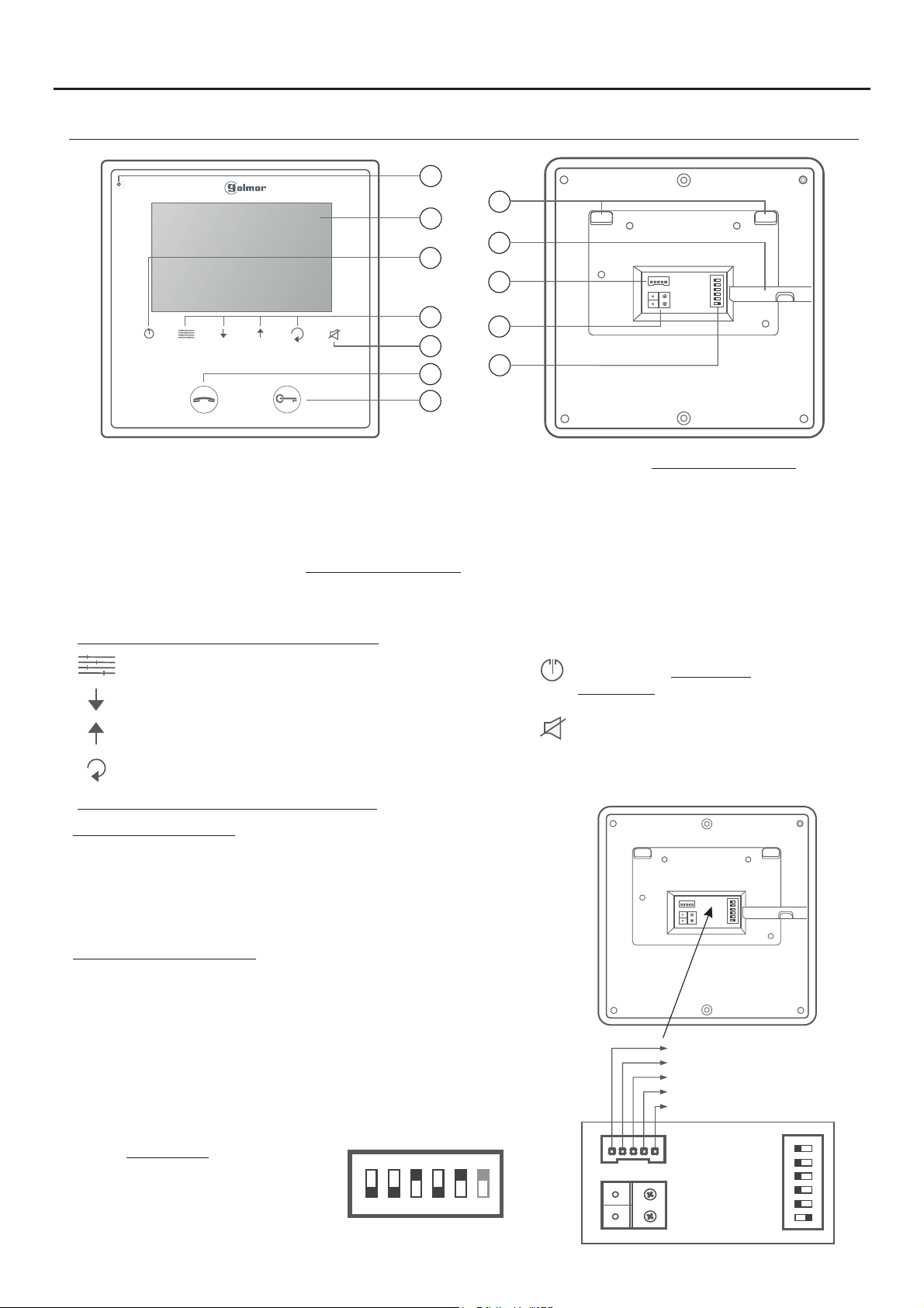
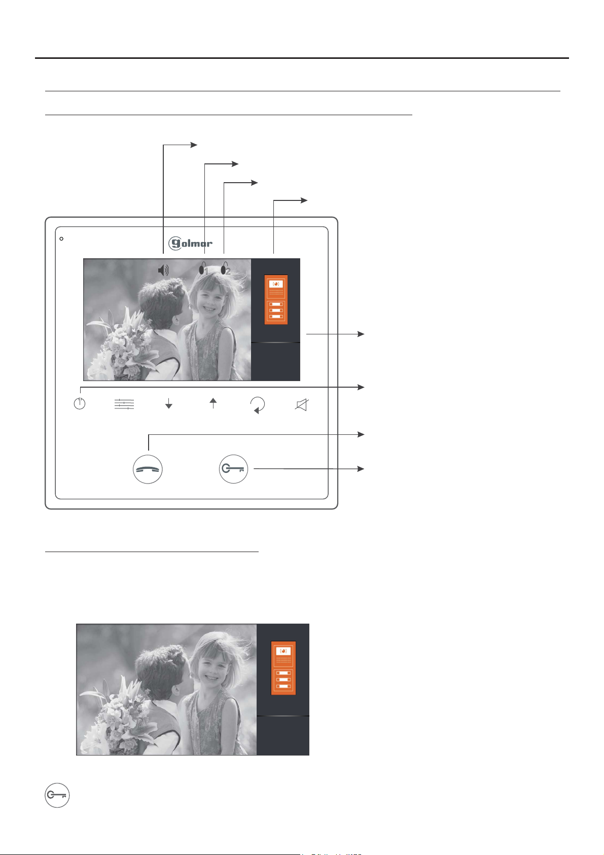
MONITOR DESCRIPTION
4
a
h
b
c
i
ON DIP
j
1 2 3
4 5 6
a. .Microphone
b. 4.3” TFT colour screen.
c. .Close push button
d. Menu push buttons.
e. “Do not disturb” push button/indicator.
f. .Start/stop communication function push button
During standby: Display door panel image.
Menu push buttons and status LEDs:
Menu accessand functionselection push button.
Menu scroll down push button.
Menu scroll up push button.
Menu back push button.
Installation terminals and dip switch:
d
k
e
f
l
g
g. releaseDoor .function push button
During standby: Press for 10 seconds to
activate/deactivate the “doctor mode” function
(function code[9018] must be activated).
h. Attachment holes.
i. .Horizontal cable input
j. Connector.
k. BUS connection terminals.
l. .Configuration DIP switch
Power supply .status LED
Push button: .End call/communication
During standby: Enter/exit menu mode.
“Do not disturb” function access push button.
LED on: “do not disturb” modeactivated.
LED blinking: “doctor mode” activated.
LED off: function not activated.
Connection terminals:
L1, L2: BUS connection (non-polarised).
HZ+, HZ-: .Door bell push button connection
CALL REPEATER, GND: Call repeater connection (SAR-12/24).
(12Vcc/50mAmaximum).
Configuration dip switch:
Dip6: Sets the end of line. Set to ON in monitors where the bus cable
terminates. Set to OFF only in intermediate monitors.
Dip1 to Dip5: Set the monitor address (addresses 0 to 31).
Switches set to OFF have a value of zero.
The values of the switches set to ON are shown in the enclosed chart.
The monitor code will be the sum of the values of the switches set to
ON.
Value chart
Switch number: 1 2 3 4 5
valueON : 1 2 4 8 16
E : 0 + 0+ 4+ 0 +16 = 20xample
ON DIP
1 2 3
4 5 6
ON DIP
1 2 3
4 5 6
( ):YELLOW
( ):BLACK GND
(R ):ED CALL REPEATER
( ):GREEN HZ-
( ):WHITE HZ+
L1
DO NOT USE
1 2 3
4 5 6
ON
DIP
L2
Page 5
VESTA2 G 2 MONITORB
MONITOR DESCRIPTION
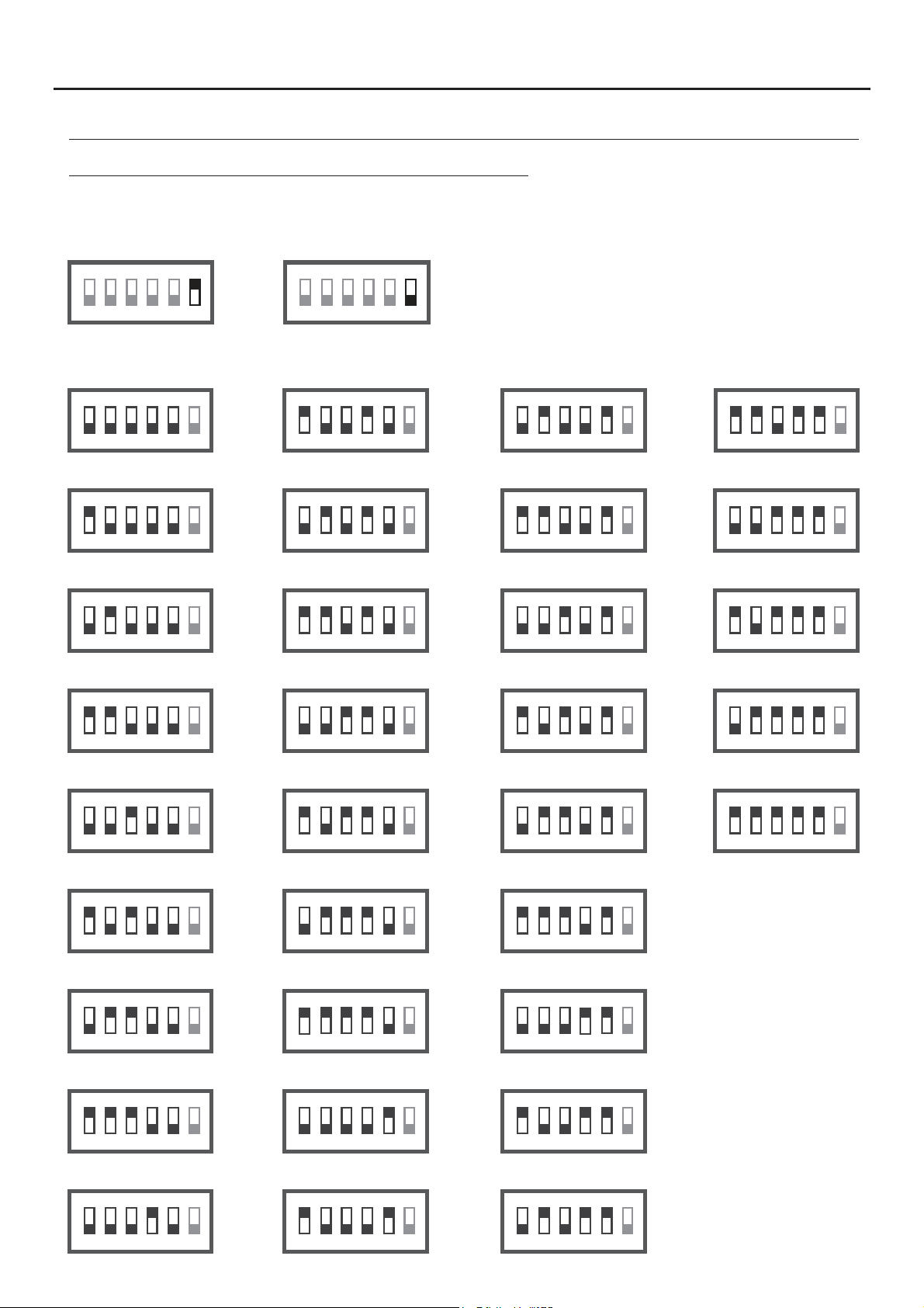
Setting the monitor's address codes (addresses 0 to 31):
Dip6: Sets the end of line. Set to ON in monitors where the bus cable terminates. Set to OFF only in intermediate
monitors.
5
Dip6 ONto
ON DIP
1 2 3
4 5 6
Dip6 OFFto
ON DIP
1 2 3
4 5 6
Dip1 Dip5:to Set the monitor address (addresses 0 to 31).
C 00ode
ON DIP
1 2 3
4 5 6
C 01ode
ON DIP
1 2 3
4 5 6
C 02ode
ON DIP
1 2 3
4 5 6
C 03ode
ON DIP
C 09ode
ON DIP
1 2 3
4 5 6
C 10ode
ON DIP
1 2 3
4 5 6
C 11ode
ON DIP
1 2 3
4 5 6
C 12ode
ON DIP
C 18ode
ON DIP
1 2 3
4 5 6
C 19ode
ON DIP
1 2 3
4 5 6
C 20ode
ON DIP
1 2 3
4 5 6
C 21ode
ON DIP
C 27ode
ON DIP
1 2 3
4 5 6
C 28ode
ON DIP
1 2 3
4 5 6
C 29ode
ON DIP
1 2 3
4 5 6
C 30ode
ON DIP
1 2 3
4 5 6
C 04ode
ON DIP
1 2 3
4 5 6
C 05ode
ON DIP
1 2 3
4 5 6
C 06ode
ON DIP
1 2 3
4 5 6
C 07ode
ON DIP
1 2 3
4 5 6
C 08ode
ON DIP
1 2 3
4 5 6
C 13ode
ON DIP
1 2 3
4 5 6
C 14ode
ON DIP
1 2 3
4 5 6
C 15ode
ON DIP
1 2 3
4 5 6
C 16ode
ON DIP
1 2 3
4 5 6
C 17ode
ON DIP
1 2 3
4 5 6
C 22ode
ON DIP
1 2 3
4 5 6
C 23ode
ON DIP
1 2 3
4 5 6
C 24ode
ON DIP
1 2 3
4 5 6
C 25ode
ON DIP
1 2 3
4 5 6
C 26ode
ON DIP
1 2 3
4 5 6
C 31ode
ON DIP
1 2 3
4 5 6
1 2 3
4 5 6
1 2 3
4 5 6
1 2 3
4 5 6
Page 6

VESTA2 G 2 MONITORB
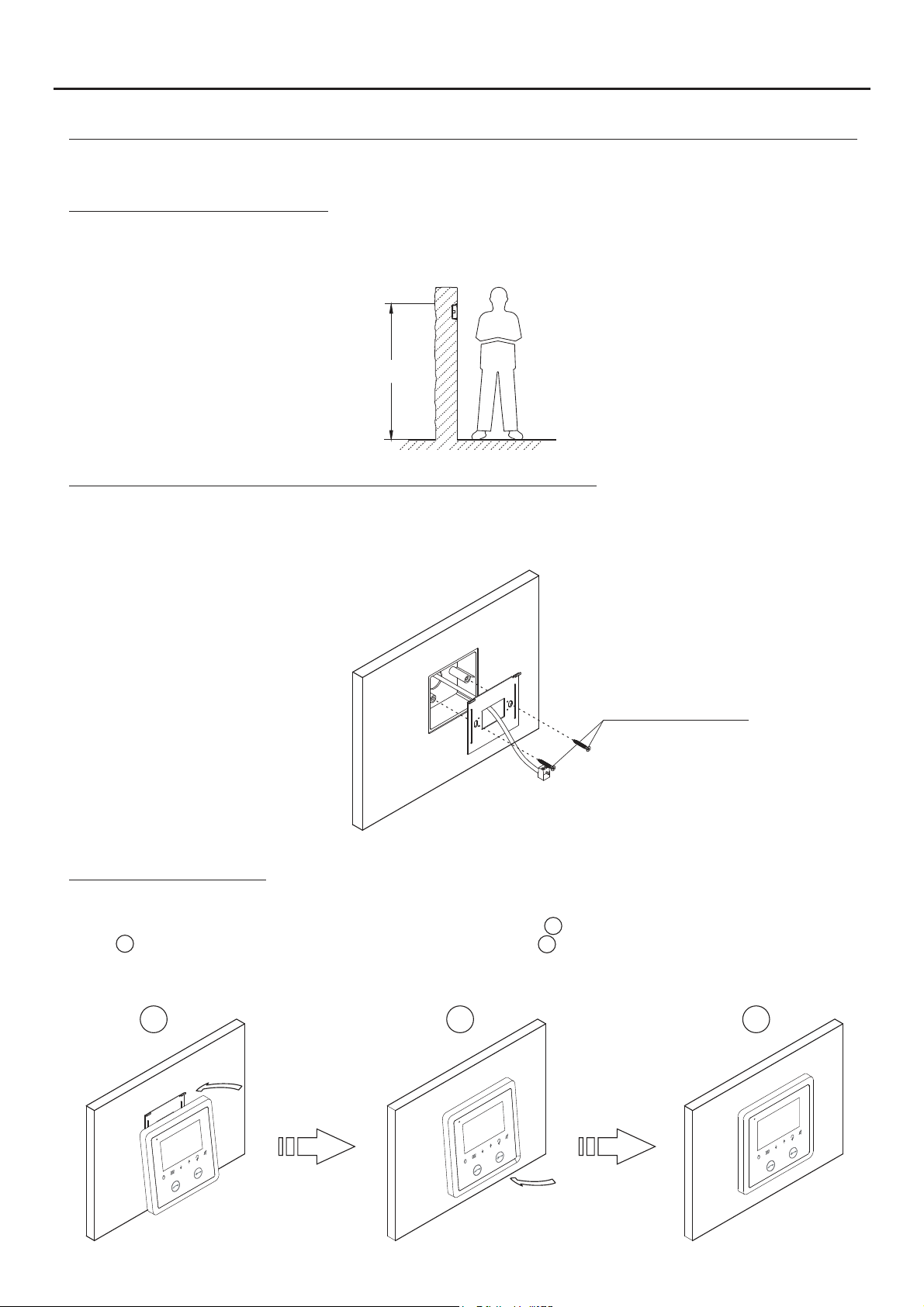
INSTALLATION OF THE MONITOR IN A SURFACE BOX
Avoid dusty or smoky environments or locations near sources of heat.
Positioning the surface box:
The upper part of the surface box must be placed at a height of 1.60m. The minimum distance between the sides of the
surface box and the closest object must be 5cm.
1 6. 0m
Fixing the monitor's surface box to the wall:
Fix the monitor's surface box to the wall by drilling two 6mm diameter holes and using the screws and plugs supplied
with the monitor.
6
x4 30
Positioning the monitor:
Connect the cables to the monitor (see page 4), position the monitor perpendicular to the terminal block ensuring that
the holes in the base of the monitor line up with those on terminal block and then move the monitor towards terminal
2
block until the monitor is fixed with the magnets located on monitor .
Remember to remove the protective covering from the front of the monitor once installation has been
completed
1
3
1 2 3
Page 7
VESTA2 G 2 MONITORB
INSTALLATION OF THE MONITOR IN AN EMBEDDING BOX
Avoid dusty or smoky environments or locations near sources of heat.
Positioning the embedding box:
Make a hole in the wall to position the top of the universal embedding box at a height of 1.60m from the ground. The
minimum distance between the embedding box and the closest object must be 5 cm.
1 6. 0m
Positioning the embedding box and mounting the terminal block:
Pass the cable through the hole made in the embedding box. Embed the box and ensure that it is level and flush.
Fix the terminal block of the monitor with the screws supplied with the embedding box.
7
Screws supplied with the
embedding box.
Positioning the monitor:
Connect the cables to the monitor (see page 4), position the monitor perpendicular to the terminal block ensuring that
the holes in the base of the monitor line up with those on terminal block and then move the monitor towards terminal
2
block until the monitor is fixed with the magnets located on monitor .
Remember to remove the protective covering from the front of the monitor once installation has been
completed.
1
3
1 2 3
Page 8
VESTA2 G 2 MONITORB
OPERATION
Monitor description upon receiving a call and during communication:
Communication activated.
Door 1 activated.
Door 2 activated.
Elapsed call/communication time.
8
1
2
1.1 Receiving a call from the door panel:
00:30
DS-1
Door panel that made the call.
End call/communication.
Start/stop communication.
Activate door release.
When a call is received, the monitor(s) will play a melody and show the door panel image on the main monitor without
alerting the visitor.If the call is not answered within 40 seconds the monitor returns to standby.
00:30
DS-1
To open the door, press the door release push button during the call: one press will activate the lock release for 5
seconds.
Continued overleaf
Page 9
VESTA2 G 2 MONITORB
OPERATION
Continued from the previous page.
1.2 :The call is unanswered (resident unavailable)
When a call is received, the monitor(s) will play a melody and show the door panel image on the main monitor without
alerting the visitor.If the call is not answered within 40 seconds the monitor returns to standby.
00:30
DS-1
9
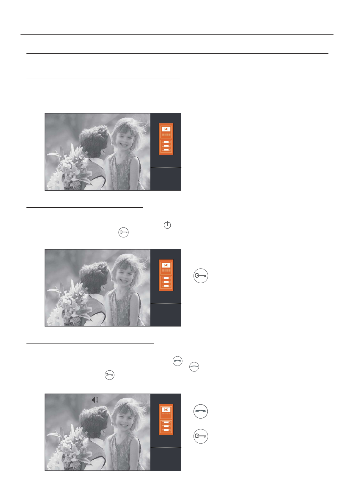
1.3 Ending a call from the door panel:
When a call is received, the monitor(s) will play a melody and show the door panel image on the main monitor without
alerting the visitor. Toend the call, press push button .
To openthe door, press pushbutton during thecall process: one press will activate the lock release for 5 seconds.
00:30
To open the door, press the door release push
button during the call: one press will activate
the lock release for 5 seconds.
DS-1
1.4 :Answering a call from the door panel
When a call is received, the monitor(s) will play a melody and show the door panel image on the main monitor without
alerting the visitor. Toanswer the call, press push button .
Communication will last for one and a half minutes or until button is pressed again.
To open the door, press button during the communication or call processes: one press will activate the lock release
for 5 seconds.
00:30
DS-1
Start/stop communication.
To open the door, press the door release push
button during the communication or call
processes: one press will activate the lock
release for 5 seconds.
Continued overleaf
Page 10

VESTA2 G 2 MONITORB
OPERATION
Continued from the previous page.
1.5 “Doctor mode” function (automatic door opening):
Descrip :tion
The “doctor mode” function allows lock release 1 to activate automatically 6 seconds after making a call from the door
panel without having to establish communication or pressing door release push button . The main monitor will
display the door panel image without alerting the visitor.The call ends after 40 seconds and the channel is freed.
Enabling “doctor mode”:
To enabledoctor mode, enter function code [9018] in the installer setup (see pages 24 and 25).
Installer setup
[ ]
9018
10
Activating“doctor mode”:
To activate doctor mode, the monitor must be in standby mode. Then press push button for 10 seconds. Status
LED will blink to indicate that the doctor mode function is activated.
Deactivating “doctor mode”:
To deactivate doctor mode, the monitor must be in standby mode. Then press push button for 10 seconds. Status
LED will turn off to indicate that the doctor modefunction is deactivated.
Important:
When activating “Do not disturb” mode (with the monitor's “doctor mode” activated), the status LED will change from
blinking to fixed andthe “doctor mode” function will be cancelled.
When deactivating “Do not disturb” mode (with the monitor's “doctor mode” activated), the status LED will blink and the
“doctor mode” function will be reactivated.
Page 11

VESTA2 G 2 MONITORB
SCREEN AND VOLUME SETTINGS MENU
To adjust contrast, the monitor must be in communication or auto switch-on mode. Then press push button to display
the “Contrast” option on screen. Using menu push buttons and , select the required contrast level. Press push
button to change thenextoption, “Brightness”,or press to exit the settings menu.
00:30
Contrast: 5
DS-1
To adjust brightness, the monitor must be in communication or auto switch-on mode. Then press push
button repeatedly until option “Brightness” is displayed on screen. Using menu push buttons and , select the
required brightness level. Press push button to change thenext option,“Colour”, or press to exit the settings menu.
00:30
11
Bri : 5ghtness
DS-1
To adjust colour, the monitor must be in communication or auto switch-on mode. Then press push button repeatedly
until option “Color” is displayed on screen. Using menu push buttons and , select the required colour level. Press push
button to change the next option, “Volume”,or press to exit thesettings menu.
00:30
Color: 5
DS-1
To adjust communication volume, the monitor must be in communication or auto switch-on mode. Then press push
button repeatedly until option “Volume” is displayed on screen. Using menu push buttons and , select the required
volume level. Press push button to return to option “Brightness” or press to exitthe settings menu.
00:30
DS-1
Volume: 6
Page 12

VESTA2 G 2 MONITORB
USER MENU
Description of the menu push buttons:
Main menu
Camera/Door
Intercom
Playback
Do not disturb
12
Menu accessand functionselection push button.
Menu scroll down push button.
Menu scroll up push button.
Menu back push button.
Menu exit push button.
To access the menu, the monitor must be in standby. Then press menu push button to display the first options
screen of the main menu.
First menu screen
Main menu
Camera Door/
Intercom
Playback
Do not disturb
Use menu push buttons and to scrollthrough the different options and access the second screen of the main menu.
First menu screen
Main menu
Camera Door/
Intercom
Second menu screen
Main menu
Divert
Light
Playback
Do not disturb
Settings
About
Continued overleaf
Page 13

VESTA2 G 2 MONITORB
USER MENU
Continued from the previous page.
1. Displaying door panel/camera images:
1.1 To display the image from one of the installed door panels, use push buttons and to go to option
“Camera/Door” and press push button . The following selection screen will be displayed. Go to the option
corresponding to door panel “DS” from which to visualisean image.
First menu screen
Selection screen
13
Main menu
Camera Door/
Intercom
Playback
Do not disturb
Select
DS-1
DS-2
DS-3
DS-4
The following screen will display the image from the selected door panel with address 1, it will also indicate the selected
door panel 'DS-1' and the elapsed connection time.
The connectionwill last for 30 seconds or until option is pressed.
To establish audio and video communicationwith the selected door panel press push button . The screen will display
symbol . Communication will last for one and a half minutes or until push button is pressed again or option is
pressed.
To open the door, press push button during the image display or communication processes: one press will activate
the lock release for 5 seconds.
00:30
DS-1
This symbol is displayed only when communication mode is enabled.
00:30
DS-1
Continued overleaf
Page 14

VESTA2 G 2 MONITORB
USER MENU
Continued from the previous page.
1.2 To display the image from one of the installed cameras (D-CAM-GB2 module required), use`push
buttons and to go to option “Camera/Door” and press push button . The following selection screen will be
displayed. Use push buttons and to go to the option corresponding to camera “CM”from whichto visualise an image.
14
First menu screen
Main menu
1ª Pantalla de menú
Camera Door/
Intercom
Playback
Do not disturb
Selection screen
Select
CM-1
CM-2
CM-3
CM-4
The following screen will display the image from the selected camera with address 1, it will also indicate the selected
camera 'CM-1' and the elapsed connection time.
The connection will last for 30 seconds or until option is pressed.
00:30
CM-1
Continued overleaf
Page 15

VESTA2 G 2 MONITORB
USER MENU
Continued from the previous page.
2. Intercom :calls
Use push buttons and to go to option “Intercom” and press push button . The following selection screen will be
displayed.
15
First menu screen
Main menu
Camera Door/
Intercom
Playback
Do not disturb
Selection screen
Select
Name List Call
Call Guard Unit
Inner call
2.1 To access the intercom calls between apartments function, use push buttons and to go to option “Name List
Call” and press push button . The following selection screen will be displayed. Use push buttons and to select
the apartmentto be called.
IMPORTANT: Activate function codes [8017] and [9015] in the monitor (see “installer setup” on pages 24 and 25).
Selection screen
Select
Name List Call
Call Guard Unit
Inner call
“Name List Call” selection screen
Name List Call
[00]
[01]
[02]
[03]
Then press push button to make the call. The following call screen will be displayed indicating the address of the
apartment to be called.A long audible tone confirms the call is being made. A series of short audible tones indicates the
call cannot be made because the unit being called is communicating either with the door panel or another apartment. If
the call is beingmade, press option to cancel the call.
“Name List Call” selection screen
Name List call
[00]
[01]
[02]
[03]
Making an intercom call
01
P ...lease wait
Continued overleaf
Page 16

VESTA2 G 2 MONITORB
USER MENU
Continued from the previous page.
In the called apartment the monitor/s will emit a melody indicating an intercom call and display the address of the
apartment making the call. Press push button to accept the call and establish communication or press
option to cancel it. If the call is accepted, communication will last for one and a half minutes or until push
button is pressed again or option is pressed.
Receiving an intercom call During communication
16
00
If during an intercom call there is a call from the door panel to either apartment, the said intercom call will be cancelled. The
monitor will emit a melody notifying the incoming call and the image will appear on the master monitor. To establish
communication with the door panel press push button on the monitor. If there are slave monitors in the apartment,
presspush button on either of these.
The reproduced acoustic tones are different depending on their provenance, which allows the user to distinguish where
the call is madefrom.
00
Continued overleaf
Page 17

VESTA2 G 2 MONITORB
USER MENU
Continued from the previous page.
2.2 To make a call to the building's monitorguard (if there is one), use push buttons and to go to option “Call Guard
Unit”and press push button .The followingcall screen will be displayedindicating the address 'GU'of the surveillance
monitor to be called. A long audible tone confirms the call is being made. A series of short audible tones indicates the call
cannot be made because the surveillance monitor is communicating with another apartment. If the call is being made,
pressoption to cancelthe call.
IMPORTANT: It is recommended to activate function code [8017] in the monitor (see “installer setup” on pages 24 and 25).
17
Selection screen
Select
Name List Call
Call Guard Unit
Inner call
The surveillance monitor will emit a melody indicating an incoming call and display the address of the apartment making
the call. Press push button to accept the call and establish communication or press option to cancel it. If the call
is accepted, communication will last for one and a half minutes or until push button is pressed again or option is
pressed.
Receiving an intercom call
00
Making an intercom call
GU
P ...lease wait
During communication
00
If an apartment receives a call from the door panel while calling or communicating with the surveillance monitor, the call to
the surveillance monitor will be cancelled. The apartment's monitor will emit a melody notifying the call from the door
panel and the image will appear on the master monitor. To establish communication with the door panel press push
button on the monitor. If there are slave monitors in the apartment, presspush button on either of these.
The reproduced acoustic tones are different depending on their provenance, which allows the user to distinguish where
the call is madefrom.
Continued overleaf
Page 18

VESTA2 G 2 MONITORB
USER MENU
Continued from the previous page.
2.3 To access the intercom calls within an apartment function, use push buttons and to go to option “Inner call”
and press push button . The following call screen will be displayed, a long audible tone confirms the call is being
made. A series of short audible tones indicates the call cannot be made because a monitor in the apartment is
communicating withthe door panel. If the call is being made,press option to cancel the call.
IMPORTANT: It is recommended to activate function code [8017] in the monitor (see “installer setup” on pages 24 and 25).
18
Selection screen
Select
Name List Call
Call Guard Unit
Inner call
A melody coming from the rest of the monitors in the apartment indicates an incoming intercom call. Press push
button to accept the call and establish communication or press option to cancel it. If the call is accepted,
communicationwill last for one and a half minutes or until push button ispressed again or option is pressed.
Receiving an intercom call
Making an intercom call
P ...lease wait
During communication
If during an intercom call there is a call from the door panel, the said intercom call will be cancelled. The monitor will emit a
melody notifying the incoming call and the image will appear on the master monitor. To establish communication with the
door panel press push button on the monitor. If there are slave monitors in the apartment, press push button on
either of these.
if during an intercom call there is a call from another apartment, the said intercom call will be cancelled. The monitor will
emit a melody notifying the incoming call and display the address of the apartment making the intercom call, (see
“Intercomcalls betweenapartments”page 15).
The reproduced acoustic tones are different depending on their provenance, which allows the user to distinguish where
the call is madefrom.
Continued overleaf
Page 19

VESTA2 G 2 MONITORB
USER MENU
Continued from the previous page.
3. :Do not disturb mode
Use push buttons and to go to option “Do not disturb” and press push button . The following selection screen will
be displayed.
19
First menu screen
Main menu
Camera Door/
Intercom
Playback
Do not disturb
Selection screen
Do not disturb
Normal
1 hour
8 h sour
Always
3.1 To activate do not disturb mode, use push buttons and to go to option “Always” and press push button .
Status LED will turn on indicating that the function is activated. The monitor will not receive door panel nor intercom
calls. Todeactivatedo not disturb mode, seesection“3.4 To deactivate do not disturb mode”on page 20.
Selection screen
Do not disturb
Normal
1 ourh
8 h sour
Always
3.2 To activate the timed “1 hour” do not disturb mode, use push buttons and to go to option “1 hour” and
press push button . Status LED will turn on indicating that the function is activated. The monitor will not receive
door panel nor intercom calls. Do not disturb mode will be activated for 1 hour. To deactivate do not disturb mode before
the end of the timed 1 hour, see section “3.4 To deactivatedo not disturb mode” on page 20.
Selection screen
Do not disturb
Normal
1 hour
8 hours
Always
Continued overleaf
Page 20

VESTA2 G 2 MONITORB
USER MENU
Continued from the previous page.
3.3 To activate the timed “8 hours” do not disturb mode, use push buttons and to go to option “8 hour” and press
push button . Status LED will turn on indicating that the function is activated. The monitor will not receive door
panel nor intercom calls. Do not disturb mode will be activated for 8 hours. To deactivate do not disturb mode before the
end of the timed8 hours,see section “3.4 To deactivatedo not disturb mode” on page 20.
Selection screen
Do not disturb
Normal
1 hour
8 h sour
Always
20
3.4 To deactivate do not disturb mode, press status LED to display the do not disturb “selection screen” and then
use push buttons and to go to option “Normal”and press push button . Status LED will turn off to indicate
thatthe function is deactivated.
Monitor in standby
Selection screen
Do not disturb
Normal
1 ho ru
8 h sour
Always
4. Divert call mode (GSM-GB2 module required):
Use push buttons and to go to option “Divert” and press push button . The following selection screen will be
displayed.
Second menu screen
Main menu
Selection screen
Divert options
Divert
Light
Settings
About
No divert
If no answer
Divert calls
Edit numbers
Tel:
Continued overleaf
Page 21

VESTA2 G 2 MONITORB
USER MENU
Continued from the previous page.
To edit fixed or telephone numbers-line cellular , use push buttons and to go to option “Edit numbers” and press
button to display the following telephone number editing screen.
Selection screen
Editing screen
21
Divert options
No divert
If no answer
Divert calls
Edit numbers
Tel:
Input numbers
0
Press push button and using push buttons and enter the first telephone number. Then press push button to
enter the next telephone number; repeat the previous steps until the complete telephone number has been entered. To
saveand exit, press option .
Editing screen
Input numbers
6
Editing screen
Input numbers
6191718XX
The following editing screen with the edited telephone number will be displayed. usingSelect the required divert option
buttons and . Then press pushbutton and pressoption to exit.
Selection screen
Divert options
No divert
If no answer
Divert calls
Edit numbers
Tel: 6191718XX
Door panel call mode, no divert.
Door panel call mode, divert if not answered within 30 seconds.
Door panel call mode, immediate divert.
Edit the fixed or telephone number.-line cellular
The second menu screen will be displayed with icon if the selected option is with divert.
Second menu screen
Main menu
Divert
Light
Settings
About
Continued overleaf
Page 22

VESTA2 G 2 MONITORB
USER MENU
Continued from the previous page.
5. Settings (ringtone, ring volume, auto switch-on time and language selection):
Usepushbuttons and to go to option “ ” and press push button . The first selectionscreen will be displayed.Settings
22
Second menu screen
Main menu
Divert
Light
Settings
About
First selection screen
Adjust
Ring Tune
Ring Volume
Autoswitch ON Time
Language
5.1 To access the ringtones, use push buttons and to go to option “Ring Tune” and press push button . The
second selectionscreenwill be displayed.
First selection screen
Settings
Ring Tune
Ring Volume
Autoswitch ON Time
Language
Second menu screen
Ring Tune
DS
Intercom
Door Bell
To change the door panel and intercom ringtones and the door bell, use push buttons and to go to the required
option and press push button . The following selection screen will be displayed. Use push buttons and to select
the required ringtone. Press option toexit and return to thesecondselectionscreen.
Selection screenSecond menu screen
Ring Tune
DS
Intercom
Door Bell
Press option to go to the first selection screen.
Tune Select
Current: 12
First selection screenSecond menu screen
Ring Tune
DS
Intercom
Door Bell
Settings
Ring Tune
Ring Volume
Autoswitch ON Time
Language
Continued overleaf
Page 23

VESTA2 G 2 MONITORB
USER MENU
Continued from the previous page.
5.2 To access the ring volume, use push buttons and to go to option “Ring volume” and press push button . The
following selection screen will be displayed. Use buttons and to select the ring volume. Press option to exit and
return to the first selectionscreen.
First selection screen
Selection screen
23
Settings
Ring Tune
Ring Volume
Autoswitch ON Time
Language
Adjust
Current: 6
5.3 To access the auto switch-on time setting, use push buttons and to go to option “Autoswitch ON Time” and
presspush button . The following selection screen will be displayed. Use pushbuttons and to selectthe required
time.Press option to exit and return to the firstselection screen.
First selection screen
Settings
Ring Tune
Ring Volume
Autoswitch ON Time
Language
Selection screen
Adjust
Current: 30sec
5.4 To access the language selection setting, use push buttons and to go to option “Language” and press push
button . The following selection screen will be displayed.
First selection screen
Settings
Ring Tune
Ring Volume
Autoswitch ON Time
Language
Selection screen
Language
English
Spanish
French
Portugues
Use push buttons and to select the language. Press push button to confirm and then press option to exit and
return to the first selectionscreen. Toreturnto the menu screen without making a change, press option .
Selection screen
Language
English
Spanish
French
First selection screen
Settings
Ring Tune
Ring Volume
Autoswitch ON Time
Portugues
Language
Continued overleaf
Page 24

VESTA2 G 2 MONITORB
USER MENU
Continued from the previous page.
Press option to go to the second menu screen.
First selection screen
24
Second menu screen
Settings
Ring Tune
Ring Volume
Autoswitch ON Time
Language
Main menu
Divert
Light
Settings
About
6. About (information, default settings and installer setup):
Using push buttons and go to option “About” and press push button . The following selection and information screen
will be displayed.
Second menu screen
Main menu
Divert
Light
Settings
About
Selection and information screen
About
H/W: a1.1
S/W: 00.02.02
Addr: 00.00
Video STD: AUTO
Restore
6.1 To access the default settings function, press push button . The following screen will be displayed. Press push
button again to confirm and retain the default settings (ringtone, ring volume and auto switch-on time) in “5. Settings”
(see page 22)or press option toreturn to the previousscreen without executing this function.
Selection and information screen
About
H/W: a1.1
S/W: 00.02.02
Addr: 00.00
Video STD: AUTO
Restore
Restore ?
6.2 To access the installer setup on the monitor's selection and information screen, press push button for 4 seconds.
Thefollowing setupscreen will be displayed.
Selection and information screen
About
H/W: a1.1
S/W: 00.02.02
Addr: 00.00
Installer Setup
[ ]
0000
Video STD: AUTO
Restore
Continued overleaf
Page 25

VESTA2 G 2 MONITORB
USER MENU
Continued from the previous page.
Use push buttons and to enter the first function code number and then press pushbutton to enterthe next function
code number; repeat the previous steps until the complete function code number is entered. Confirm the function code
entered by pressing push button . To return to the previous screen, press option . (See installer function codes on
page 25).
Selection and information screen
25
Installer setup
[ ]
8000
H/W: a1.1
S/W: 00.02.02
Addr: 00.00
Video STD: AUTO
About
Restore
Function codes (installer):
[8000]: . [8001] [8003]:Master monitor (factory) Slave monitor 1 to3.to
*
[8004]: Guard . [8005]: guardmonitor Without monitor (factory).
*
[8014]: . [8015]: .With second lock release menu Without second lock release menu (default setting)
( )
[8016]: Not active m . [8017]:Yes active m .enuif BUS is busy(defaultsetting) enu if BUS is busy
( )
( )
2
[9015]: . [9016]:Intercom calls enabled Intercom calls disabled (default setting).
Each apartmentmust have only one master unit:Any further units in the apartment mustbe configured as slaves.
*
( )
1
It is recommended to activate function code [8017]: If there is more than one monitor in the apartment and an intercom call
1
needs to be made.
( )
( )2( )
1
It is recommended to activate function codes [8017] and [9015]: To make an intercom call between apartments.
Press option to go to the second menu screen.
Selection and information screen
About
H/W: a1.1
S/W: 00.02.02
Addr: 00.00
Video STD: AUTO
Restore
To exit the monitor's user menu function, press option or .
Second menu screen
Main menu
Divert
Light
Settings
About
Second menu screen
Main menu
Divert
Light
Settings
About
Monitor in standby
Page 26

VESTA2 G 2 MONITORB
SECOND DOOR RELEASE MENU
To access the second door release menu, press push button during a call, communication or auto switch-on
process. The following selection screen will be displayed. Use push buttons and to select door release 1 or door
release 2 .
2
Second door release menu screen
1
26
Then press push button .
1
Door ctivated1 a
00:30
DS-1
00:30
DS-1
00:30
1
2
DS-1
IMPORTANT: Function code [8014] must be activated in the monitor (see“Installersetup” on pages 24 and 25).
CLEANING THE MONITOR
- Do not use dissolvents, detergents or cleaning products that contain acids,
vinegar or abrasive components.
- Use a soft, damp cloth (not wet) that does leave lint behind.
- Always wipe the monitor in the same direction, from top to bottom.
- After cleaning the monitor remove any moisture using a soft, dry cloth
that doesn't leave lint behind.
Page 27

VESTA2 G 2 MONITORB
NOT S:E
27
Page 28

VESTA2 G 2 MONITORB
USER MENU (ANNEX)
“Playback” menu option (MM-GB2 module and FA-GB2 power supply required):
Description of the menu push buttons:
Menu push buttons and status LEDs:
Menu accessand functionselection push button.
Main menu
Camera Door/
Intercom
Playback
Do not disturb
Menu scroll down push button.
Manual recording push button: During a call,
communication or auto switch-on process.
Menu scroll up push button.
Menu back push button.
28
Status LED
:
Fi : .xed power On
Blinking: Door panel call videos yet to be
displayed.
Push button:
Status LED blinking: Press to access the
“Playback” menu.
Status LED fixed: Enter/exit menu mode.
Note: The monitor makes an automatic video recording 6 seconds after receiving a call from the door panel.
Viewing door panel call/camera videos and deleting videos (MM-GB2 module and FA-GB2 power supply required):
To access the menu, the monitor must be in standby. Then press menu push button to display the first options
screen of the main menu.
First menu screen
Main menu
Camera Door/
Intercom
Playback
Do not disturb
To display call/camera videos, use push buttons and to go to option “Playback” and press push button . The
followingselection screen willbe displayed.Use push buttons and to select the video to display. The durationof each
videois 10 seconds.
First menu screen
Main menu
Camera Door/
Intercom
Playback
Do not disturb
Selection screen
2016/02/02 17 : 46' : 12"
Continued overleaf
Page 29

VESTA2 G 2 MONITORB
USER MENU (ANNEX)
Continued from the previous page.
To delete the selected video, press option . “ ” will be displayed on the screen. Press push button toDelete?
confirm the deletion or press option to cancel the deletion and return to the previous screen.
29
Selection screen
2016/02/02 17 : 46' : 12" Delete?
Selection screen
2016/02/02 17 : 46' : 12"
To exit option “Playback” and return to the first menu screen, press push button .
Selection screen
2016/02/01 15 : 32' : 25"
First menu screen
Camera Door/
Intercom
Playback
Do not disturb
Main menu
To exit the monitor's user menu function, press option or .
First menu screen
Main menu
Camera Door/
Intercom
Playback
Do not disturb
Monitor in standby
To change the date and time, go to option “ ” (as shown on page 22) and then press push button for 3Settings
seconds. The following “Date & Time” settings screen will be displayed. Press push button to move over the
date/time setting and use push buttons and to change the values. Press option to save and then press
option to exit the user menu function.
Settings selection screen
Settings
Ring Tune
Ring Volume
Date and time settings screen
Date&Time
2016 - 02 - 03
10 : 51 : 40
Autoswitch ON T
Language
ime
 Loading...