

Page 1
Installation & Operation M anual
Te43 Outdoor Auxiliary Enclosure
Page 2

This page is intentionally left blank.
Alpha Technologies Ltd. 057-104-B0 Rev D WC
Printed in Canada. © 2010 Alpha Technologies Ltd. ALPHA and CORDEX are trademarks of Alpha Technologies Ltd. All Rights Reserved.
Page 3

Te43 Outdoor Auxiliary Enclos ure
057-104-20-101
The following documents and drawings are included in this manual to provide the necessary information required for
routine operation and fault diagnosis o the system:
Specifications: 029-030-B2
CSA/NRTL Equivalence 048-554-10
Safety and Installation Instructions 057-104-C0
Schematic 747-612-05
Outline drawings 057-104-06
Cust Connect, Intfc Kit, Te41 to Te40 w Cabl 747-602-08
Cust Connect, Intfc Kit, Te40 to Te40 w Cabl 747-603-08
Cust Connect, Intfc Kit, Te41 to Te40 w/o Cabl 747-607-08
Cust Connect, Interface Kit, Nokia Bridge 747-595-08
Cust Assy, Kit, 9” Top Extension 747-531-F0
Cust Assy, Kit, Plinth w/ Mounting Hard ware 747-592-F0
Cust Assy, Kit, 4x Cable Boot for Top Ext 747-627-F0
Alpha Technologies Ltd. 057-104-B0 Rev D WC
Printed in Canada. © 2010 Alpha Technologies Ltd. ALPHA and CORDEX are trademarks of Alpha Technologies Ltd. All Rights Reserved.
Page 4
Burnaby, British Columbia. Telephone: 604 436 5900 Fax: 604 436 1233.
Alpha Technologies Ltd.
Important Safety Instructions
Save These Instructions
This section contains important instructions that must be followed during the installation and maintenance of the
equipment and batteries. Read all of the instructions before installing or operating the equipment, and save this
manual for future reference.
All electrical connections must be performed by licensed electricians only. Installation of the power supply and
batteries must be performed by, or under the direct supervision of, service personnel knowledgeable of the
required electrical and battery safety procedures.
If instructions in this manual conflict with the local electrical codes, follow the local codes.
The following safety symbols are found throughout this manual. Carefully read all information and abide by the
instructions:
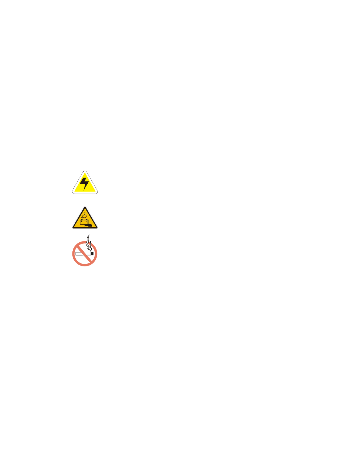
DANGEROUS VOLTAGE
This symbol indicates a dangerous voltage
exists in this area of the product.
GAS HAZARD
This symbol indicates a gas hazard
exists in the area of vented batteries.
The following warning levels are used in conjunction with the symbols:
DANGER: You WILL be KILLED or SERIOUSLY INJURED if instructions are not followed closely.
WARNING: You CAN be KILLED or SERIOUSLY INJURED if instructions are not followed closely.
CAUTION: You CAN be INJURED or equipment can be DAMAGED if instructions are not followed closely.
Mechanical safety
Keep hands and tools clear of fans. Fans are thermostatically controlled and switch on automatically.
Power supplies can reach extreme temperatures under load.
Use caution around sheet metal components and sharp edges.
NO MATCHES OR OPEN FLAMES
This symbol indicates a fire or explosive hazard
exists in the area of the product.
Page 5

Burnaby, British Columbia. Telephone: 604 436 5900 Fax: 604 436 1233.
Alpha Technologies Ltd.
Electrical safety
WARNING: Hazardous voltages are present at the input of power systems. The DC output from rectifiers
and batteries, though not dangerous in voltage, has a high short-circuit current capacity that may cause
severe burns and electrical arcing.
Before working with any live battery or power system, follow these precautions:
Remove all metallic jewelry, such as watches, rings, metal rimmed glasses, or necklaces.
Wear safety glasses with side shields at all times during the installation.
Use OSHA approved insulated hand tools.
DANGER: Lethal voltages are present within the power system. Always assume that an electrical
connection or conductor is energized. Check the circuit with a voltmeter with respect to the grounded
portion of the enclosure (both AC and DC) before performing any installation or removal procedure.
Do not work alone under hazardous conditions.
A licensed electrician is required to install permanently wired equipment. Input voltages can range up to
240 Vac. Ensure that the utility power is disconnected and locked out before performing any installation
or removal procedure.
Ensure that no liquids or wet clothes come into contact with internal components.
Hazardous electrically live parts inside this unit are energized from the batteries even when the AC input power is
disconnected.
Battery safety
Servicing and connection of batteries must be performed by, or under the direct supervision of, personnel
knowledgeable of batteries and the required safety precautions.
Always wear eye protection, rubber gloves, and a protective vest when working near batteries. Remove all
metallic objects from your hands and neck.
Use OSHA approved insulated hand tools. Do not rest tools on top of batteries.
Batteries contain or emit chemicals known to cause cancer and birth defects or other reproductive harm. Battery
post terminals and related accessories contain lead and lead compounds. Wash your hands after handling
batteries.
WARNING: Follow battery manufacturer’s safety recommendations when working around battery
systems.
WARNING: Do not smoke or introduce an open flame when batteries (especially vented batteries) are
charging. When charging, batteries vent hydrogen gas, which can explode.
Batteries are hazardous to the environment and should be disposed at a recycling facility. Consult the battery
manufacturer for recommended local authorized recyclers.
Post installation weather proofing
After installing the conduits and removing any knockouts to accommodate conduit locations, ensure that any gaps
between the conduit fittings and the shroud are sealed. Apply a weatherproof caulking to gaps to prevent wind
driven rain from reaching the electrical equipment.
Page 6

Alpha Technologies Ltd. 057-104-C0 Rev B WC
Burnaby, British Columbia. Telephone: 604 436 5900 Fax: 604 436 1233. Page 1 of 27
Table of contents
1 Introduction ............................................................................................................................ 4
1.1 Scope of manual ................................................................................................ ........................ 4
1.2 Product overview ........................................................................................................................ 4
1.3 Recommended pre-installation training ...................................................................................... 4
1.3.1 Cordex controller operation ............................................................................................... 4
1.3.2 Enclosure installation ........................................................................................................ 4
2 Features ................................................................................................................................. 5
2.1 Equipment compartment ................................................................ ............................................ 5
2.2 Equipment mounting rails ........................................................................................................... 5
2.3 Heating, ventilating, and air conditioning (HVAC) ....................................................................... 7
2.4 Security ...................................................................................................................................... 8
2.5 Rear access panel ..................................................................................................................... 9
2.6 Removable solar shield and hatch plate ..................................................................................... 10
3 Transportation and storage .................................................................................................... 11
3.1 Packaging .................................................................................................................................. 11
3.2 Storage ...................................................................................................................................... 11
3.3 Site Considerations .................................................................................................................... 11
3.4 Inspection................................................................................................................................... 11
4 Installation .............................................................................................................................. 12
4.1 Pre-installation considerations .................................................................................................... 12
4.1.1 Site selection ..................................................................................................................... 12
4.1.2 Enclosure support ............................................................................................................. 12
4.1.3 Base layout dimensions .................................................................................................... 13
4.1.4 Concrete slab .................................................................................................................... 14
4.1.5 Steel platform .................................................................................................................... 15
4.2 Installation component requirements .......................................................................................... 16
4.3 Installation tools and equipment ................................................................................................. 17
4.3.1 Tools Required .................................................................................................................. 17
4.3.2 Lifting equipment requirements ......................................................................................... 17
Page 7

Alpha Technologies Ltd. 057-104-C0 Rev B WC
Burnaby, British Columbia. Telephone: 604 436 5900 Fax: 604 436 1233. Page 2 of 27
4.4 Enclosure installation ................................................................................................................. 18
4.4.1 Enclosure preparation ....................................................................................................... 18
4.4.2 Lifting preparation ............................................................................................................. 18
4.4.3 Mounting the enclosure ..................................................................................................... 19
4.4.4 Installing multiple enclosures side-by-side......................................................................... 19
4.4.5 Enclosure-to-enclosure interface ....................................................................................... 20
4.4.6 Top hat installation ............................................................................................................ 21
4.4.7 Enclosure compartment integrity ....................................................................................... 21
4.5 Grounding .................................................................................................................................. 22
4.5.1 Site ground wire entry ................................................................................................ ....... 22
4.5.2 Master ground bus (MGB) ................................................................................................. 22
4.5.3 Enclosure chassis ground ................................................................................................. 22
4.6 Air conditioner connections ........................................................................................................ 23
5 Test and commissioning ........................................................................................................ 24
5.1.1 Environmental/intrusion ..................................................................................................... 24
5.2 Final cleanup .............................................................................................................................. 24
6 Maintenance .......................................................................................................................... 25
6.1 General maintenance schedule .................................................................................................. 25
6.2 Air conditioner ............................................................................................................................ 25
6.2.1 Air conditioner settings ...................................................................................................... 25
6.2.2 Air conditioner filter ........................................................................................................... 25
6.2.3 High temperature alarms and air conditioner failures ........................................................ 25
7 HVAC default settings ............................................................................................................ 26
7.1 Air Conditioner/heater ................................................................................................................ 26
7.2 Temperature alarms ................................................................................................................... 26
8 Alpha conventions ................................................................................................................. 27
8.1 Numbering system ..................................................................................................................... 27
8.2 Acronyms ................................................................................................................................... 27
Page 8

Alpha Technologies Ltd. 057-104-C0 Rev B WC
Burnaby, British Columbia. Telephone: 604 436 5900 Fax: 604 436 1233. Page 3 of 27
List of figures
Figure 1 – Tempest Te43 Outdoor Battery Enclosure............................................................................... 4
Figure 2 – Miscellaneous compartment features ................................................................ ...................... 5
Figure 3 – Alarm block ............................................................................................................................. 6
Figure 4 – Miscellaneous enclosure features ........................................................................................... 7
Figure 5 – Front door handle security ....................................................................................................... 8
Figure 6 – Top cover and rear panel intrusion alarm switch ..................................................................... 8
Figure 7 – 24” top panel ........................................................................................................................... 9
Figure 8 – Other panels ............................................................................................................................ 9
Figure 9 – Base layout drawing and mounting hole location for Te43 ....................................................... 13
Figure 10 – Concrete anchor bolt fastening detail .................................................................................... 14
Figure 11 – Installation on steel platform .................................................................................................. 15
Figure 12 – Example of an insulated tool kit ............................................................................................. 17
Figure 13 – Secure hooks in eyebolts ...................................................................................................... 18
Figure 15 – Gasket on lower side panel ................................................................................................... 20
Figure 14 – Typical enclosure-to-enclosure mounting .............................................................................. 20
Figure 16 – Enclosure ground connections .............................................................................................. 22
Figure 17 – Battery enclosure air conditioner connections ....................................................................... 23
Page 9
Alpha Technologies Ltd. 057-104-C0 Rev B WC
Burnaby, British Columbia. Telephone: 604 436 5900 Fax: 604 436 1233. Page 4 of 27
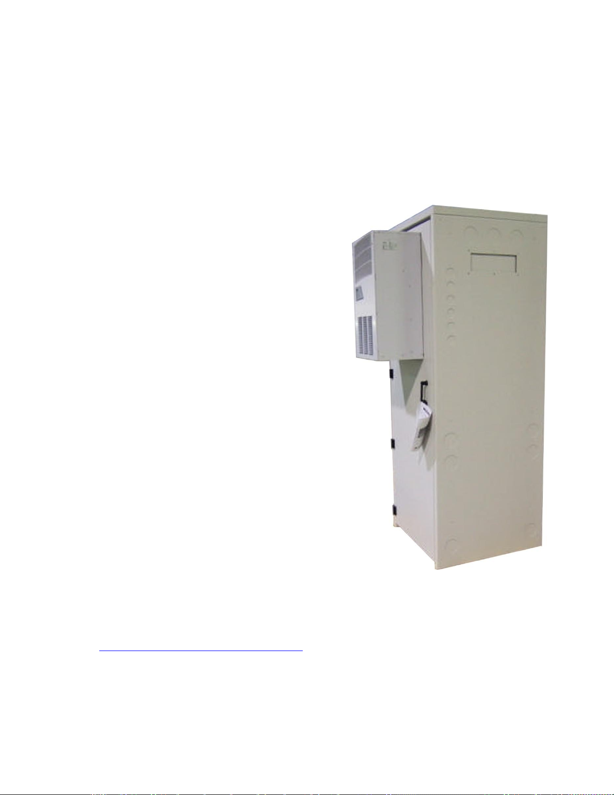
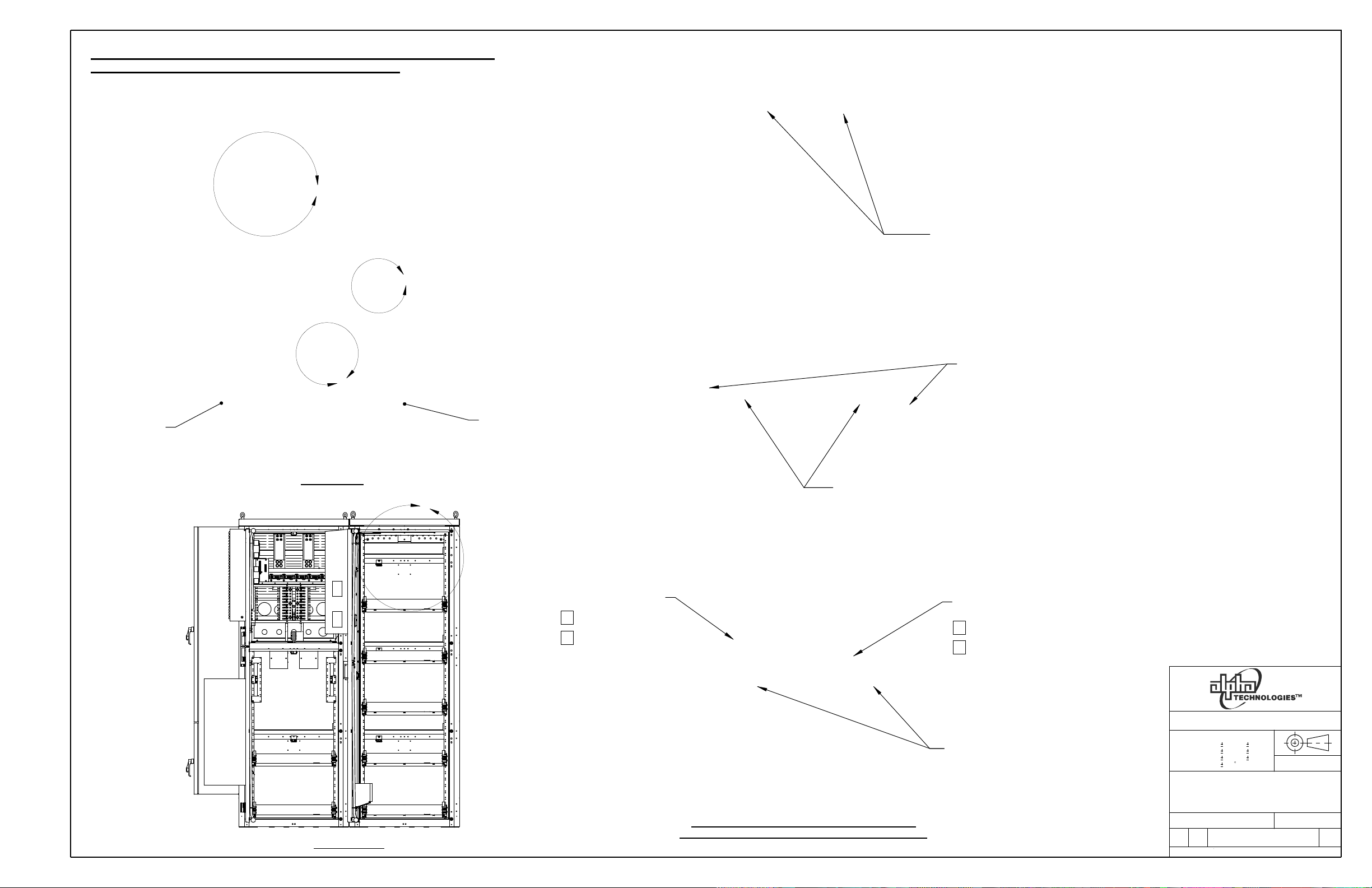
Figure 1 – Tempest Te43 Outdoor Auxiliary Enclosure
1 Introduction
1.1 Scope of manual
This instruction manual covers features, installation, startup, and maintenance of the Alpha Technologies’
Tempest Te43 Outdoor Auxiliary Enclosure.
Enclosure specifications are found in Alpha document #029-030-B2.
Operation instructions for the system controller and related modules are provided in separate component
manuals.
Separate manuals are provided for batteries and other accessory equipment, such as HVAC.
Images contained in this document are for illustrative purposes only and may not exactly match your unit.
1.2 Product overview
The Te43 Outdoor Auxiliary Enclosure is designed to be
used in conjunction with Alpha power enclosures (Te4x) or
other stand-alone equipment.
A Te43 system typically includes:
Zone 4 seismic enclosure design
AC junction box for HVAC equipment
Mates with Alpha outdoor power enclosure Te41
Front access, side-to-side inter-bay mating
Alarm interface
1.3 Recommended pre-installation training
1.3.1 Cordex controller operation
Go to http://www.argus.ca/web2/training-center.html and then find “Alpha Courses and Training” under Technical
Support Documents.
1.3.2 Enclosure installation
Courses are available on an “as needed” basis. Contact the factory for details.
Free emergency technical support:
North America 1-888-462-7487; Outside North America +604-436-5547
Page 10
Alpha Technologies Ltd. 057-104-C0 Rev B WC
Burnaby, British Columbia. Telephone: 604 436 5900 Fax: 604 436 1233. Page 5 of 27
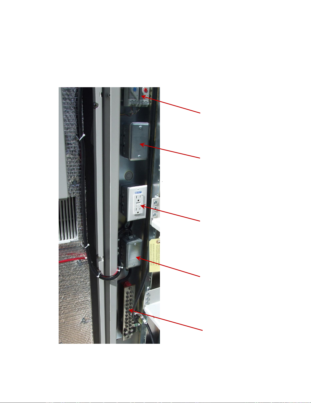
Air conditioner utility box
High/low temperature
alarm thermostats
GFCI outlet
Master ground bar
Spare utility box
Figure 2 – Miscellaneous compartment features
2 Features
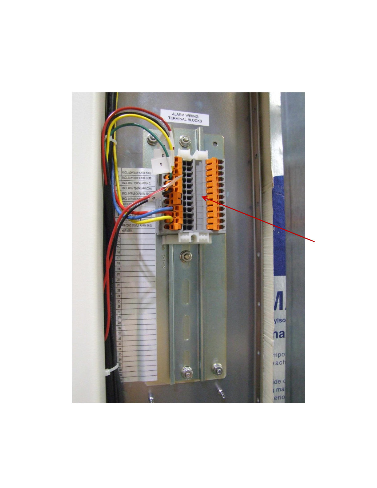
2.1 Equipment compartment
The air-conditioned auxiliary enclosure is equipped with alarm wiring, an AC load termination for the air
conditioner, a GFCI outlet, and a master ground bar.
2.2 Equipment mounting rails
Four rails are installed in the enclosure. The rails are adjustable to a width of 19" or 23" (standard) and are also
adjustable front-to-back.
Page 11
Alpha Technologies Ltd. 057-104-C0 Rev B WC
Burnaby, British Columbia. Telephone: 604 436 5900 Fax: 604 436 1233. Page 6 of 27
Figure 3 – Alarm block
Alarm block
Page 12
Alpha Technologies Ltd. 057-104-C0 Rev B WC
Burnaby, British Columbia. Telephone: 604 436 5900 Fax: 604 436 1233. Page 7 of 27
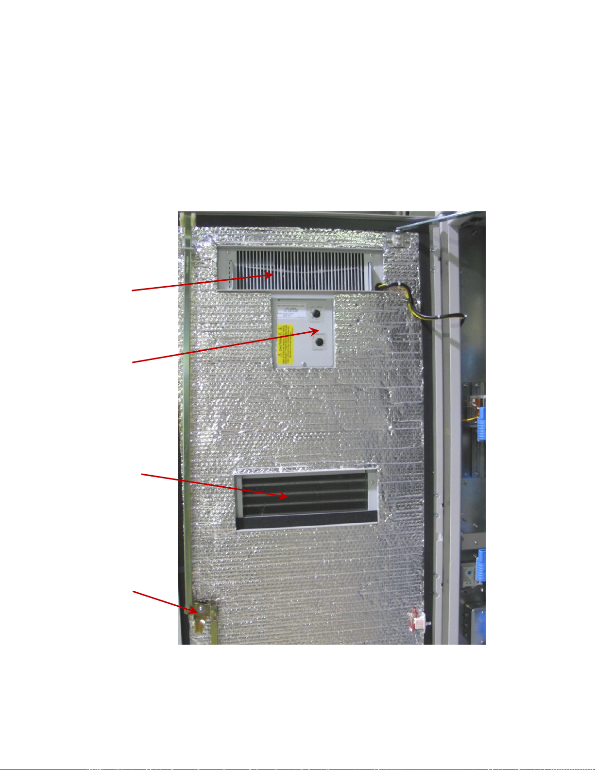
Three-point door latch
Figure 4 – Miscellaneous enclosure features
HVAC exhaust
HVAC controls
HVAC intake
2.3 Heating, ventilating, and air conditioning (HVAC)
An air conditioner/heater package is mounted on the front door of the enclosure. It provides cooling/heating for
the batteries and customer equipment. Refer to the HVAC manual supplied with the unit for operation and
maintenance details.
Page 13
Alpha Technologies Ltd. 057-104-C0 Rev B WC
Burnaby, British Columbia. Telephone: 604 436 5900 Fax: 604 436 1233. Page 8 of 27
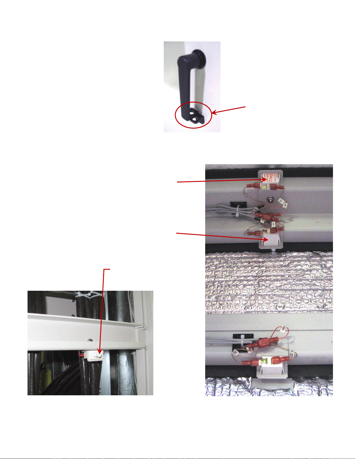
Once closed, the front door handle
can be secured with a padlock
Top cover intrusion alarm switch
Rear panel intrusion alarm switch
One per panel
Switches can be offset-mounted
Figure 5 – Front door handle security
Figure 6 – Top cover and rear panel intrusion alarm switch
2.4 Security
The front door can be padlocked:
Page 14
Alpha Technologies Ltd. 057-104-C0 Rev B WC
Burnaby, British Columbia. Telephone: 604 436 5900 Fax: 604 436 1233. Page 9 of 27
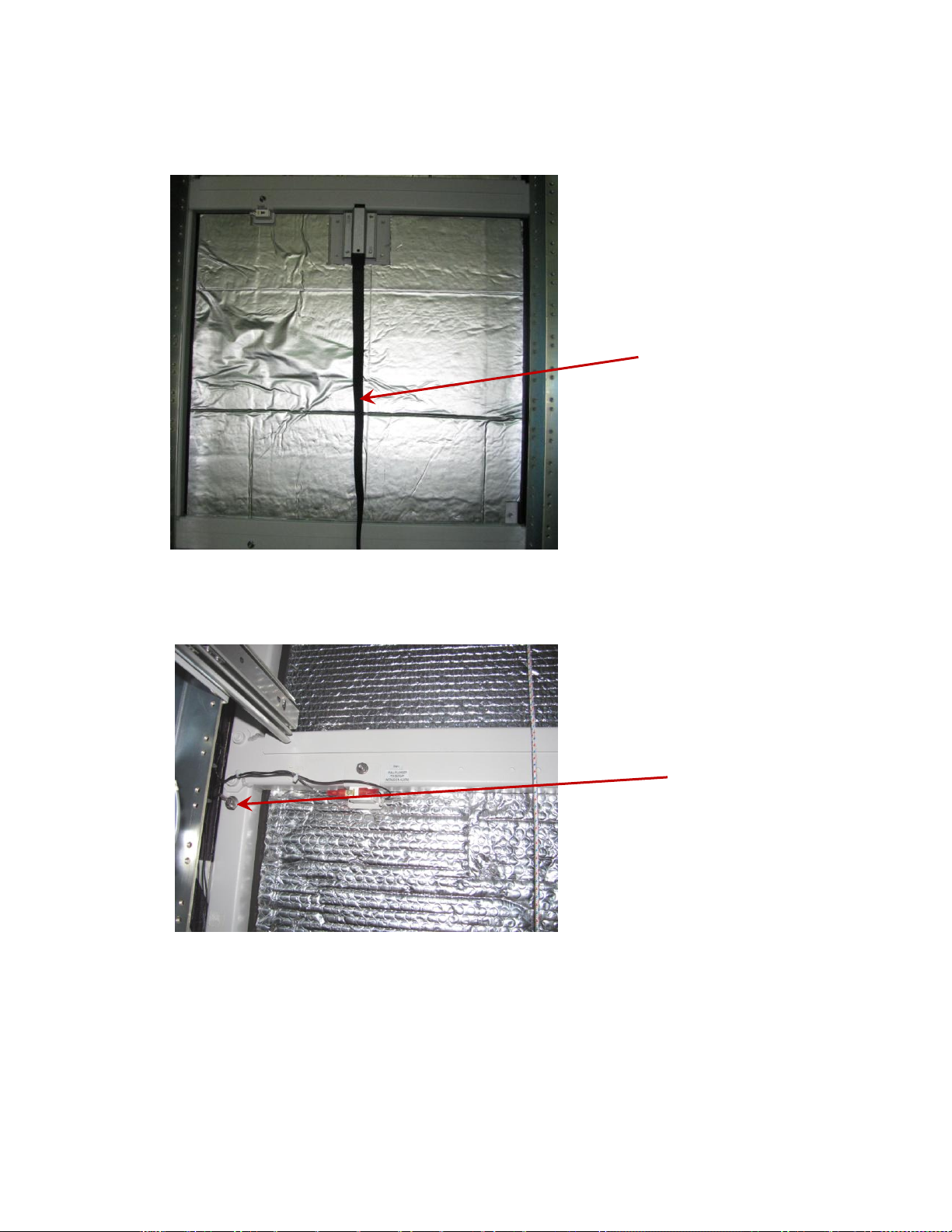
Pull on strap to release
top 24”rear panel, then
lift the panel up and out
of the enclosure.
Remove each set of wing
nuts, one on each side, to
release the other panels.
Figure 7 – 24” top panel
Figure 8 – Other panels
2.5 Rear access panel
There are four removable rear access panels, one top 8” panel and three 24” panels below. The 24” panel directly
below the 8” top panel is a slam latch panel. The top 8” panel and the lower two 24” panels use internal wing-
studs that must be removed to lift off the panels.
When installing the rear panels, first install the lower panel, then the next one up, then the top 8” panel, and finally
the top 24” slam latch rear panel.
Page 15
Alpha Technologies Ltd. 057-104-C0 Rev B WC
Burnaby, British Columbia. Telephone: 604 436 5900 Fax: 604 436 1233. Page 10 of 27
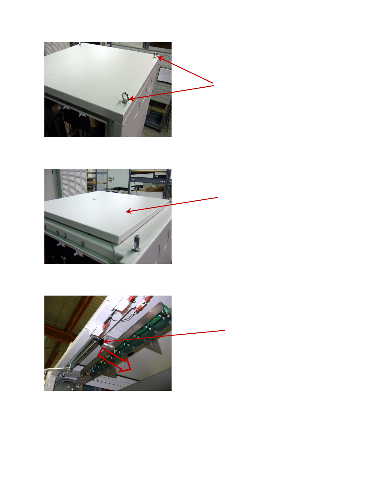
Remove eyebolts
Remove solar shield exposing hatch plate
To release hatch plate, pull the latch
ring toward the rear of the enclosure
in the direction shown by the large
arrow
2.6 Removable solar shield and hatch plate
To re-install, ensure the slam latch on the hatch plate is fully engaged.
Re-install the solar shield by re-installing the eyebolts.
Page 16

Alpha Technologies Ltd. 057-104-C0 Rev B WC
Burnaby, British Columbia. Telephone: 604 436 5900 Fax: 604 436 1233. Page 11 of 27
3 Transportation and storage
3.1 Packaging
The enclosure and components are shrink wrapped and shipped on individual pallets. The enclosures and
components must not be stacked on top of each other.
The pallet is approximately 0.15 m H x 1.22 m W x 1.22 m D (6" H x 48" W x 48" D). The overall height including
the pallet and enclosure is approximately 2.3 m (91").
Batteries are shipped on a separate pallet and packaged according to the manufacturer’s guidelines. Packaging
assemblies and methods have been tested to International Safe Transit Association standards.
3.2 Storage
The weight of the enclosure is written in the specifications. The equipment pallet can be moved using a forklift.
3.3 Site Considerations
The site should be ready for the enclosure installation before the enclosure arrives. A lift truck or crane is required
to lift and position the enclosure and its components. Make sure that there are no potential obstructions in the
transport path. Use safe lifting practices.
3.4 Inspection
Before unpacking the equipment, perform a visual inspection and note any damage. Unpack the equipment and
inspect the exterior for damage. Continue the inspection for potential internal damage. Contact the carrier
immediately if internal damage is detected. Then contact Alpha Technologies for advice on the consequence of
any damage.
Verify that you have all the required parts before proceeding with the installation.
Call Alpha Technologies if you have any questions: 1-888-462-7487
Page 17

Alpha Technologies Ltd. 057-104-C0 Rev B WC
Burnaby, British Columbia. Telephone: 604 436 5900 Fax: 604 436 1233. Page 12 of 27
4 Installation
4.1 Pre-installation considerations
The information in this section is intended to be used as a guideline only. There may be site-specific requirements
and other factors that may require different procedures. For example, your jurisdictional codes and construction
covenants may require different procedures than those in this manual.
4.1.1 Site selection
The Te43 has been designed as an outdoor power system enclosure. The most common mounting structures are:
An at-grade concrete slab.
A steel platform.
An existing structure, such as a rooftop.
The mounting structure must be strong enough to support a fully equipped enclosure. Existing structures may
need to be reinforced. The mounting site must be built in accordance with local building practices and codes.
Consider the following before selecting a mounting site:
The Alpha Te43 enclosure is designed for front, rear, and if necessary top access. Only front access is
required for maintenance.
Avoid areas that may be subjected to hot air exhaust from nearby equipment or buildings.
Find out if your intended area is subjected to architectural controls or environmental restrictions.
Avoid areas that are prone to flooding.
4.1.2 Enclosure support
The empty enclosure weighs approximately 450 lb and has a base area of 6.25 ft². The supporting structure must
have a loading capacity capable of supporting this weight (72 lb/ ft²) plus the additional weight of all the equipment
installed inside the enclosure.
Page 18
Alpha Technologies Ltd. 057-104-C0 Rev B WC
Burnaby, British Columbia. Telephone: 604 436 5900 Fax: 604 436 1233. Page 13 of 27
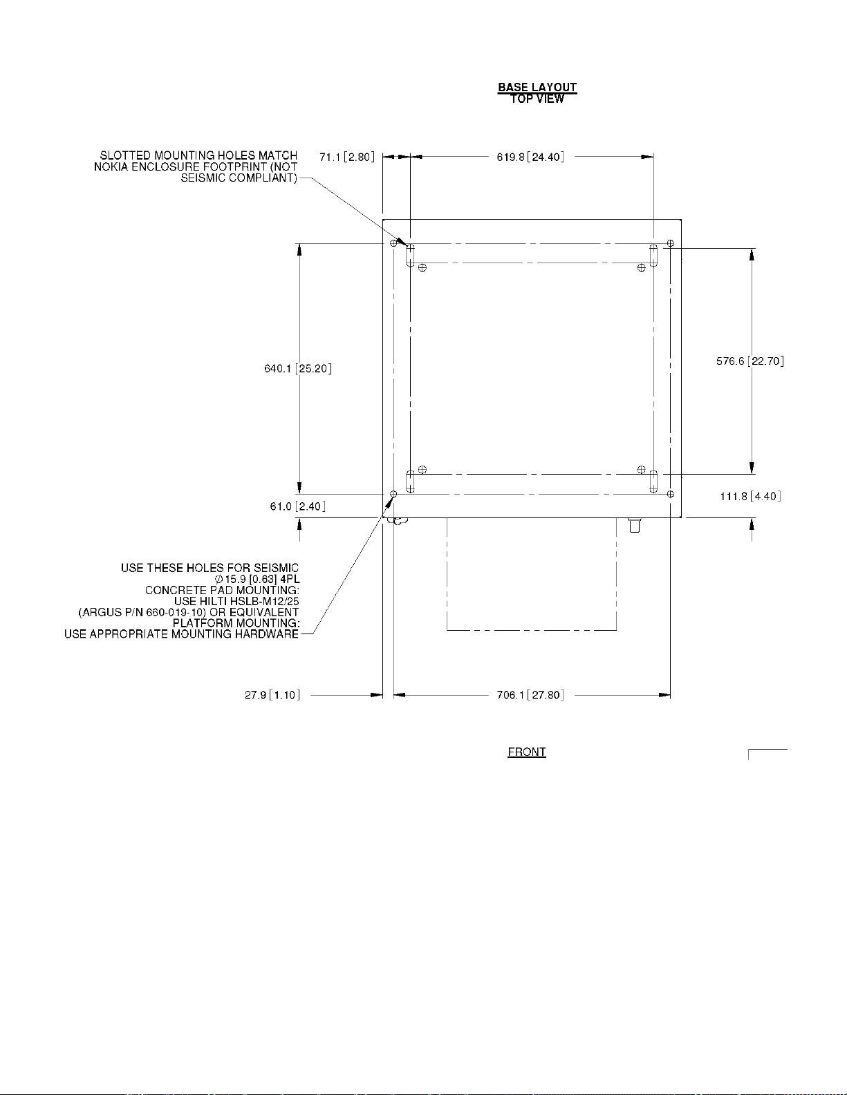
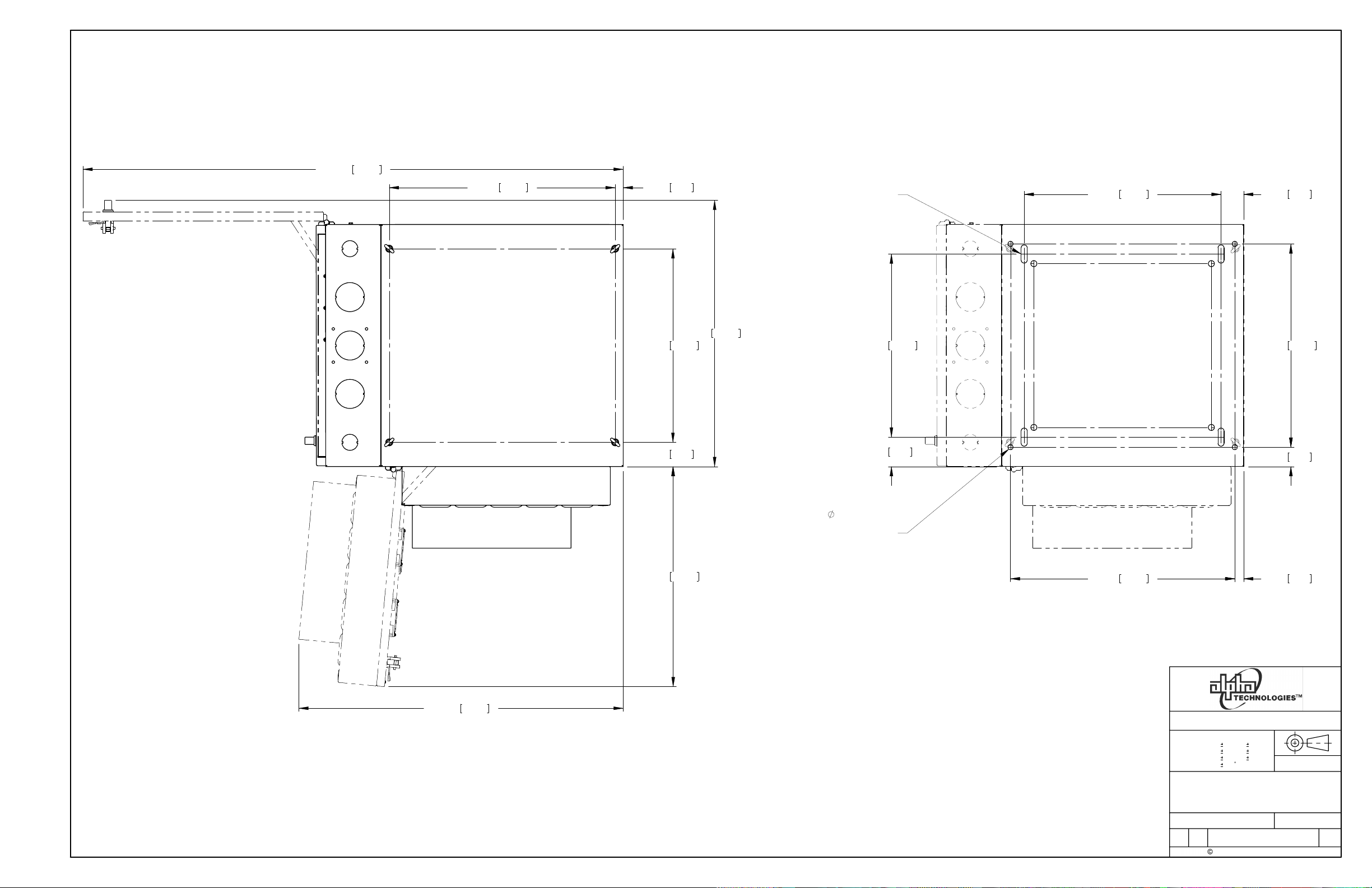
Figure 9 – Base layout drawing and mounting hole location for Te43
4.1.3 Base layout dimensions
Page 19

Alpha Technologies Ltd. 057-104-C0 Rev B WC
Burnaby, British Columbia. Telephone: 604 436 5900 Fax: 604 436 1233. Page 14 of 27
Figure 10 – Concrete anchor bolt fastening detail
4.1.4 Concrete slab
Cast-in-place or pre-cast concrete slabs can be used.
Place the enclosure on the concrete slab. Use the enclosed Hilti HSL heavy-duty expansion anchor bolts or
approved equivalents to secure the enclosure. Follow the specific recommendations from the fastener
manufacturer to ensure that the securing device achieves its full structural capacity. Take into account the
embedment depth and clear edge distances. Refer to the following figure.
Alternate mounting systems that are not provided directly with the enclosure must be reviewed by a registered
professional engineer that is qualified to practice within the jurisdiction where the enclosure is being installed.
An alternate mounting system could for example use a chemical anchoring system such as Hilti’s HY150 for
concrete or HY20 for masonry along with suitable threaded rods and inserts from the manufacturer. Follow the
manufacturer’s recommendations to determine the spacing and placement of the threaded rods.
The supporting structure must be designed to support a fully equipped enclosure. The concrete slab and any
existing structures must be properly reinforced to support the floor loading. The mounting site must be designed
and installed in accordance with local building practices and codes.
Page 20

Alpha Technologies Ltd. 057-104-C0 Rev B WC
Burnaby, British Columbia. Telephone: 604 436 5900 Fax: 604 436 1233. Page 15 of 27
Figure 11 – Installation on steel platform
4.1.5 Steel platform
Use 1.27 cm (½”) diameter A325 structural bolts in conjunction with a backing plate/clasp to grip the underside of
the grating. Once the enclosure is in place, secure the bolts on the inside using appropriate washers and bolts.
See the following figure:
CAUTION: Installation on a wood base is not recommended. The compressive strength of the base
material would not be able to maintain the load during a Type 4 seismic event.
Page 21

Alpha Technologies Ltd. 057-104-C0 Rev B WC
Burnaby, British Columbia. Telephone: 604 436 5900 Fax: 604 436 1233. Page 16 of 27
Roxtec seal port 9 way assembly
including boot, mounting collar and
hardware
Alpha part number: 037-193-20-000
Can be used for cable entry into the Te43 enclosure wherever there are 3” knockouts.
See
www.roxtec.com for additional
information
4.2 Installation component requirements
Concrete and metal grating mounting hardware is not supplied with the enclosure.
AC electrical conduit, cable and fittings are not supplied with the enclosure.
External DC conduit, cable and fittings are not supplied with the enclosure.
A cable entry port fitting is available as an option:
For multiple enclosure installations an interface kit is required.
Power to battery: 747-602-20
Battery to battery: 747-603-20
Power to battery without cables: 747-607-20.
Page 22

Alpha Technologies Ltd. 057-104-C0 Rev B WC
Burnaby, British Columbia. Telephone: 604 436 5900 Fax: 604 436 1233. Page 17 of 27
Figure 12 – Example of an insulated tool kit
4.3 Installation tools and equipment
4.3.1 Tools Required
Insulated tools are essential for DC power system installation. Use this list as a guide:
Electric drill with hammer action
Digital voltmeter equipped with test leads
Lap top computer with Cordex communication software (not required for initial installation and test)
Various crimping tools and dies, to match lugs used in installation
Torque wrench: ¼" drive, 0-150 in-lb for battery post connections
Torque wrench: 3/8" drive, 0-100 ft-lb for system connections
Insulating canvases as required (2' x 2', 1' x 1', 3' x 3', etc.)
Insulated hand tools:
-Combination wrenches -Ratchet and socket set
-Various screwdrivers -Electricians knife
-Fine tipped slot screwdrivers (“tweaker”) -Cable cutters
Cutters and wire strippers (#14 to #22 AWG) [2.5 – 34 mm2].
4.3.2 Lifting equipment requirements
Hoist or crane capable of lifting 1814 kg (4000 lb)
The forklift should have a rated lifting capacity of 1814 kg (4000 lb) with a minimum fork length of 36”
Four wire-rope slings at least 1.22 m (4') long with a capacity of 907 kg (2000 lb) each.
Four clevises.
Minimum 1.59 cm (5/8”) diameter rope to use as a tagline to guide the enclosure while lifting.
Page 23

Alpha Technologies Ltd. 057-104-C0 Rev B WC
Burnaby, British Columbia. Telephone: 604 436 5900 Fax: 604 436 1233. Page 18 of 27
Figure 13 – Secure hooks in eyebolts
4.4 Enclosure installation
4.4.1 Enclosure preparation
Remove the protective covering from the system. The doors are designed to be locked with a pad-lock and are
secured with tie-wraps for shipping. Cut the tie-wraps and open the doors. The inside of the enclosure contains
the installation hardware.
Inspect the packing slip to verify that you have received all the equipment that you ordered.
All documentation is packed inside the equipment compartment.
Inspect all moving parts, hardware, connectors, and other equipment.
Report any damage to the shipper and Alpha Technologies.
Remove and properly dispose of all packaging.
Remove the rear panels to access the rear mounting bolts.
Remove the four bolts that secure the enclosure to the pallet. These bolts are accessible from the inside of
the enclosure and are located in the corners of the enclosure. The enclosure is now ready for lifting.
4.4.2 Lifting preparation
WARNING: Follow all local safety practices and guidelines while lifting the enclosure. All personnel
involved with lifting and placing the enclosure must wear head, eye protection, gloves when required.
Only properly trained and certified personnel should operate the crane. Only properly trained and
certified personnel should operate the forklift.
Make sure that the lifting eyes are securely fastened before lifting. Ensure that the clevises are correctly installed
and that the enclosure is approximately level when it is lifted. This will simplify the enclosure placement.
Close and latch the enclosure front door. The rear panels do not need to be installed.
Place the enclosed rubber mat onto the slab or platform. Orient the mat so that the mounting holes line up.
Page 24

Alpha Technologies Ltd. 057-104-C0 Rev B WC
Burnaby, British Columbia. Telephone: 604 436 5900 Fax: 604 436 1233. Page 19 of 27
4.4.3 Mounting the enclosure
Concrete slab
Use the tagline to guide the enclosure as it is lifted. As the enclosure is lowered, align the mounting bolts and
drop the enclosure into place.
CAUTION: Follow all local safety practices and guidelines while lifting the enclosure. As the enclosure is
lowered, ensure that it remains as level as possible and lines up with the anchoring bolt locations. Ensure
the rubber mat is in the proper position. If the rubber mat is “ribbed”, the ribs should be against the
concrete. Open the door and proceed with leveling the enclosure and securing it into place.
Steel platform
If the steel platform is located at ground level, the procedures are the same as those for the concrete slab.
Roof mounting
CAUTION: The mounting platform must be installed before the enclosure can be installed. All grounding must be
in place before the installation.
Place the enclosure onto the roof using either a freight elevator with access to the roof, or a crane or hoist on the
roof.
Do not remove the enclosure from its pallet until it is on the roof and is ready to be placed.
4.4.4 Installing multiple enclosures side-by-side
If two or more enclosures are to be installed adjacent to one another, install the environmental components of the
interface kit before bolting the enclosures into place.
Page 25

Alpha Technologies Ltd. 057-104-C0 Rev B WC
Burnaby, British Columbia. Telephone: 604 436 5900 Fax: 604 436 1233. Page 20 of 27
Knock out enclosure-toenclosure holes. Bolt
enclosures together in the
top corners. Tighten the
bolts to the appropriate
torque.
Install “Nokia interface”
type gasket around conduit
openings
Figure 14 – Gasket on lower side panel
Figure 15 – Typical enclosure-to-enclosure mounting
4.4.5 Enclosure-to-enclosure interface
The cable bridge kit between the enclosures can be mounted either on the left or right side of the enclosures.
This kit must be installed before installing adjacent enclosure.
See the enclosed drawings for the interface kit assembly.
Remove the knockouts on the lower rear side panels.
Apply a gasket around the opening used for cable routing.
Page 26

Alpha Technologies Ltd. 057-104-C0 Rev B WC
Burnaby, British Columbia. Telephone: 604 436 5900 Fax: 604 436 1233. Page 21 of 27
Remove solar shield and mounting
hardware including standoffs
Install top hat and fasten with eyebolts
Install standoffs on top edge of top hat
Prepare and install the hatch panel
Add Roxtec cable entry boots or conduits
If aligned with other top hats,
install feed through fittings
Bolt the solar shield onto the enclosure
4.4.6 Top hat installation
A top hat is an optional structure. See enclosed drawings for the top hat kit assembly. Install the top hat kit before
installing adjacent enclosures.
4.4.7 Enclosure compartment integrity
The Te43 enclosure compartment is air conditioned.
Use gaskets, boots, and other sealing materials to minimize air exchange between compartments and
enclosures. This will reduce the air conditioner loading.
Similarly use gaskets, boots, and other sealing materials to prevent water from entering the enclosures. See the
enclosed drawings for more details.
Page 27

Alpha Technologies Ltd. 057-104-C0 Rev B WC
Burnaby, British Columbia. Telephone: 604 436 5900 Fax: 604 436 1233. Page 22 of 27
External chassis ground
connected to site ground.
There are two connection
points, one at the front of the
enclosure, and one at the
rear. Only one connection is
required with an exothermic
connection.
Ground wire that connects
the site ground to the
master ground bar
Figure 16 – Enclosure
ground connections
Ground studs
MGB
4.5 Grounding
DANGER: An enclosure that is not properly grounded presents an electrical hazard.
A proper grounding system that meets or exceeds the specifications of the equipment must be designed and
installed prior to or in conjunction with the construction of the mounting pad. The ground system must be bonded
to the enclosure to ensure a “common” or “single-point” ground.
Examples of grounds:
New builds – a buried ground ring with a bare, solid conductor going to ground rods.
Rooftop – a connection to the building’s steel structure, water pipes, etc.
Refer to local codes and practices for proper acceptable grounding arrangements. Only a licensed electrician
should install the grounding system. Use a dedicated ground rod for the AC panel.
CAUTION: Do not route AC and DC wiring in the same conduit.
4.5.1 Site ground wire entry
External ground studs are located at the bottom front and rear
of the enclosure. Use these to make the site ground wire
connections. Terminate either the front or rear connection to
the external ground ring with an exothermic connection. A
minimum of #2 AWG solid wire is required.
4.5.2 Master ground bus (MGB)
The master (main) ground bus is located at the lower left front corner of the enclosure. Terminate the MGB to the
external ground ring with an exothermic connection. A minimum of #2 AWG solid wire is required.
4.5.3 Enclosure chassis ground
The enclosure chassis ground is pre-installed at the factory. It is connected to the enclosure frame and equipment
racks and is terminated to the MGB inside the enclosure.
Page 28
Alpha Technologies Ltd. 057-104-C0 Rev B WC
Burnaby, British Columbia. Telephone: 604 436 5900 Fax: 604 436 1233. Page 23 of 27
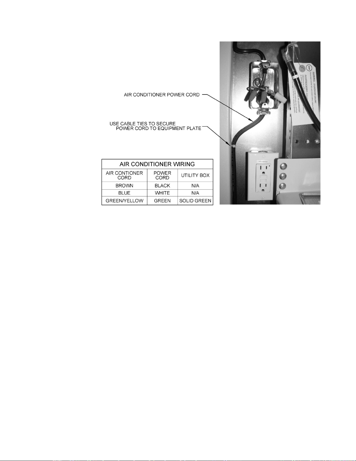
Only a licensed
electrician should
connect the AC
input power to the
enclosure
Figure 17 – Battery enclosure air conditioner connections
4.6 Air conditioner connections
Page 29

Alpha Technologies Ltd. 057-104-C0 Rev B WC
Burnaby, British Columbia. Telephone: 604 436 5900 Fax: 604 436 1233. Page 24 of 27
5 Test and commissioning
5.1.1 Environmental/intrusion
Check the operation of all enclosure features, such as the air conditioning unit settings, the high/low temperature
alarms and the intrusion alarm.
5.2 Final cleanup
Vacuum clean all metal filings and other debris from inside and around the enclosure.
Ensure that:
All cables and conduit are neatly secured.
Access panels are installed correctly.
All connections are tight.
All breakers are on and the system is running without any alarms.
Enclosure is locked and secure.
Page 30

Alpha Technologies Ltd. 057-104-C0 Rev B WC
Burnaby, British Columbia. Telephone: 604 436 5900 Fax: 604 436 1233. Page 25 of 27
Description
Interval
Clean ventilation openings
1-6 months
Inspect all cable connections, re-torque if necessary
1 year
Verify alarm/control settings
1 year
Verify alarm relay operation
1 year
Clean HVAC filter
2-6 months
6 Maintenance
The equipment requires regular maintenance. The maintenance should be done by qualified service personnel
only.
WARNING: HIGH VOLTAGE AND SHOCK HAZARD.
Use extreme care when working inside the enclosure/shelf while the system is energized. Do not make
contact with live components or parts. Static electricity may damage circuit boards, including RAM chips.
Always wear a grounded wrist strap when handling or installing circuit boards.
6.1 General maintenance schedule
6.2 Air conditioner
6.2.1 Air conditioner settings
The air conditioner is pre-programmed with default settings at the factory. Refer to the air conditioner manual if
you need to adjust these settings.
6.2.2 Air conditioner filter
Air conditioners often fail due to lack of maintenance, specifically dirty filters. Implement a structured filter
inspection/maintenance schedule to avoid unnecessary air conditioner failures.
6.2.3 High temperature alarms and air conditioner failures
The air conditioner is not always thoroughly tested at the factory. If the air conditioner fails to switch on when it
should, refer to the air conditioner manual and check the temperature settings.
If the air conditioner appears to be working properly but the “Hi-Temp” alarm is on, check that the enclosure's Hi-
Temp alarm thermostat is correctly set.
Page 31

Alpha Technologies Ltd. 057-104-C0 Rev B WC
Burnaby, British Columbia. Telephone: 604 436 5900 Fax: 604 436 1233. Page 26 of 27
Description
Setting
Cooling system ON temperature
80F (26.6C)
Heating system ON temperature
60F (15.5C)
HVAC fail alarm (dirty filter, broken condenser, etc.)
300 psi, reset at 225 psi
Compartment thermostat
Setting
High temperature alarm (blue)
45C (113F)
Low temperature alarm (red)
-15C (5F)
7 HVAC default settings
Refer to the air conditioner manual for operation and maintenance details.
7.1 Air Conditioner/heater
7.2 Temperature alarms
Page 32

Alpha Technologies Ltd. 057-104-C0 Rev B WC
Burnaby, British Columbia. Telephone: 604 436 5900 Fax: 604 436 1233. Page 27 of 27
Acronym
Definition
AC
Alternating current
AWG
American wire gauge
BTU
British thermal unit
CSA
Canadian Standards Association
CX
Cordex™ series; e.g., CXC for Cordex System Controller
DC
Direct current
GFCI
Ground fault circuit interrupter
HVAC
Heating, ventilating, and air conditioning
MGB
Master ground bus
NEMA
National Electrical Manufacturers Association
RAM
Random access memory
RU
Rack unit (1.75”)
UL
Underwriters Laboratories
VRLA
Valve regulated lead acid
8 Alpha conventions
8.1 Numbering system
Alpha Technologies uses an eight-digit drawing number system, which is broken into three blocks. The first three
digits describe the category of the product; e.g., rectifier or fuse panel. The next three digits indicate the sequence
in which the product number was allocated in a particular category. The last two digits indicate the type of
drawing, for example:
“-06” Outline Drawing
“-08” Customer Connections
“-20” Main Assembly
Alpha Technologies uses an eight-digit part numbering system for all components and sub assemblies. Each part
is covered by its own unique number. Due to the quantity, categories will not be listed within this manual.
8.2 Acronyms
The following acronyms are used in this manual:
Page 33

Specifications for Alpha Te43 Auxiliary Enclosure
Electrical
Input Voltage: 120Vac, 60Hz single phase (for air conditioner and CFGI receptacle)
Feeder Breaker: 15A recommended
Mechanical
Dimensions: 2134mm H x 762mm W x 762mm D
(84" H x 30" W x 30" D)
Weight: 205 kg (450 lb.)
Mounting: Pad or platform
HVAC: Air conditioner with 500-W built-in heater
Enclosure: Aluminum, 5052-H32
Environmental
Operating Temperature: -40 to +46°C
(-40 to 115°F)
Storage Temperature: -40 to +85°C
(-40 to +185°F)
Humidity: 0 to 95% non-condensing
Elevation: -50 to 4000 meters operating
(-164 to 13,123 feet)
Weather Tightness: NEMA Type 3R
Regulatory Approvals
Enclosure Ratings: CSA/UL Type 3R
IEC enclosure designation IP56
See also Environmental (above)
Telcordia: Compliance to GR-487, consult factory for detailed compliance information
Product Safety: CSA/UL 60950
The above information is valid at the time of publication. Consult factory for up-to-date ordering information.
Specifications are subject to change without notice.
Alpha Technologies Ltd. 029-030-B2 Rev B WC
Printed in Canada. © 2010 Alpha Technologies Ltd. ALPHA is a registered trademark of Argus Technologies Ltd. All Rights Reserved.
Page 34

1
2
3
4
5
6
REVISION
LTR
DESCRIPTION
DATE APPD
AIR CONDITIONER AND GFCI WIRING:
A A
BLK
WHT
GRN
8
9
10
TO TB9
N.C.
TO TB10
COM
TO TB11
N.O.
WIRE NUTS
TO ALARM WIRING TERMINAL BLOCKS
(REFER TO SHEET 2)
LINE
NEU
GND
120V SINGLE PHASE AC INPUT POWER FEED
(CUSTOMER SUPPLIED CONNECTION)
BLU - #18 AWG
4000 BTU/Hr AIR CONDITIONER
RETURN AIR
EXT. OUTPUT LEAD
(STATUS ALARM)
NOTE
DEFAULT SETPOINTS:
A/C: 27C (80F)
HEATER: 18C (65F)
AC POWER INPUT
120VAC, 60 Hz
B B
SUPPLY AIR
N.C.
COM
N.O.
LINE
NEU
GND
BLU - #18 AWG
RED - #18 AWG
YEL - #18 AWG
BRN - #16 AWG
BLU - #16 AWG
GRN - #16 AWG
BLK - #14 AWG
WHT - #14 AWG
GRN - #14 AWG
ORG
YEL
GRN - #14 AWG
LINE
NEU
GND
120V SINGLE PHASE AC INPUT POWER FEED
(CUSTOMER SUPPLIED CONNECTION)
RED - #18 AWG
YEL - #18 AWG
ORG
BONDING
SCREW
'UTILITY BOX'
BLK
J3
WHT
'WHT'
NEU
C C
GRN
YEL
BONDING
SCREW
GRN
GFCI AC RECEPTACLE
LINE
TERMINALS
HOT
TEST
RESET
J4
GND
15A/125V
'UTILITY BOX'
3:11:54 PM
Time:
2009/05/12
Date:
74761205PA_SHEET1.SCHDOC
File:
THESE DESIGNS AND SPECIFICATIONS ARE THE PROPERTY OF
ARGUS TECHNOLOGIES AND SHALL NOT BE COPIED OR USED
FOR MANUFACTURING WITHOUT ITS WRITTEN CONSENT.
DESIGN
DRAWN
J.K
J.K
09/05
09/05
MATERIAL
CHECKED
D D
NOTES:
1.) USE 14/3 SJ FLEXIBLE CORD FOR WIRING UNLESS OTHERWISE INDICATED.
APPROVED
TOLERANCES
Title
SCHEMATIC, ENCLOSURE, 84",
4K BTU A/C, V3 AUX
FINISH
SCALE
ISSUE
DATE
SIZE DWG NO.
TYPE
C
S5
1
2
3
4
5
747-612-05
Sheet of
6
1
2
Rev
P/A
Page 35

1
2
3
4
5
LTR DESCRIPTION DATE APPD
6
REVISION
ENCLOSURE TEMPERATURE & INTRUSION ALARM WIRING:
ALARM WIRING TERMINAL BLOCK
LOW TEMPERATUREHIGH TEMPERATURE
A A
DEFAULT SETTINGS:
HIGH TEMP = 45C (113F)
LOW TEMP = -15C (5F)
B B
ALARM THERMOSTAT ALARM THERMOSTAT
50 C
30 C 70 C
3 4
15 C
- 5 C 35 C
REDBLU
1 21 2
1 2
RED - #22 AWG
BLK - #22 AWG
YEL - #22 AWG
GRN - #22 AWG
P/N 877-673-20
FROM A/C ALARM
OUTPUT
(REFER TO SHEET 1)
N.C.
COM
N.O.
RED - #22 AWG
BLK - #22 AWG
YEL - #22 AWG
GRN - #22 AWG
RED - #22 AWG
BLK - #22 AWG
8
9
10
* REFER TO TABLE 1 FOR ALARMS
1
TB1 'ENCLOSURE LOW TEMP' ALARM (N.C.)
2
TB2
3
TB3
4
TB4
5
TB5
6
TB6
NOT USED
NOT USED
BLU - #18 AWG
RED - #18 AWG
YEL - #18 AWG
NOT USED
TB7
TB8
TB9
TB10
TB11
TB12
TABLE 1 - ENCLOSURE OUTPUT ALARMS
SIGNAL DESCRIPTIONTB POS
TB1
TB2
TB3
TB4
TB5
TB6
TB7
TB8
TB9
TB10
TB11
TB12
'ENCLOSURE LOW TEMP' ALARM (COM)
'ENCLOSURE HIGH TEMP' ALARM (N.O.)
'ENCLOSURE HIGH TEMP' ALARM (COM)
'ENCL. INTRUSION' ALARM (N.C.)
'ENCL. INTRUSION' ALARM (COM)
NOT USED
NOT USED
'AIR CONDITIONER STATUS' ALARM (N.C.)
'AIR CONDITIONER STATUS' ALARM (COM)
'AIR CONDITIONER STATUS' ALARM (N.O.)
NOT USED
ENCLOSURE GROUND BAR TERMINATIONS:
12 12
P/N 877-674-20
C C
24" X 30" (BOTTOM) REAR
PANEL INTRUSION
ALARM SWITCH
P/N 538-043-10
(12 PL)
6
D D
5
1
SW3
(OPEN)(COM)
QUICK CONNECTS
MALE: P/N 538-167-10
FEMALE: P/N 538-166-10
(6 PL)
MF
RED - #22 AWG
BLK - #22 AWG
24" X 30" (MID) REAR
24" X 30" (UPPER) REAR
PANEL INTRUSION PANEL INTRUSION
ALARM SWITCH
BLK - #22 AWG BLK - #22 AWG
16 15 14 13 17
RED - #22 AWG RED - #22 AWG RED - #22 AWG RED - #22 AWG RED - #22 AWG
SW2 SW1
2
ALARM SWITCH
BLK - #22 AWG BLK - #22 AWG
(OPEN)(COM)(OPEN)(COM)
3
8" X 30" (UPPER) REAR
PANEL INTRUSION
ALARM SWITCH
SW4
(OPEN)(COM)
4
SOLAR SHIELD
INTRUSION
ALARM SWITCH
SW5
(OPEN)(COM)
BLK - #22 AWG
GRN - #6 AWG FLEX
FRONT DOOR
INTRUSION
ALARM SWITCH
SW6
(OPEN)(COM)
5
RED - #22 AWG
5
TO EQUIPMENT RACK
GND
TO EXTERNAL SITE GROUND
GND
(CUSTOMER CONNECTION)
Time:
Date:
File:
THESE DESIGNS AND SPECIFICATIONS ARE THE PROPERTY OF
ARGUS TECHNOLOGIES AND SHALL NOT BE COPIED OR USED
FOR MANUFACTURING WITHOUT ITS WRITTEN CONSENT.
Title
ISSUE
DATE
SIZE
B
3:11:54 PM
2009/05/12
74761205PA_SHEET2.SCHDOC
SCHEMATIC, ENCLOSURE,
4K BTU A/C, V3 AUX
Sheet
TYPE
DWG NO.
S5
747-612-05
6
2 2
of
Rev
P/A
Page 36

DESCRIPTION
LTR
ADDED TE43P OUTLINE
P/B
REVISIONS
DWN
RP
DATE
10/04
CHKD
DX
APPD
JK
TYP
28.40
721.4
TYP
1.60
40.6
TYP
TYP
TYP
TYP
TYP
TYP
TYP
24.00
21.00
18.00
15.00
12.00
9.00
6.00
0
762.0 30.00
609.6
533.4
457.2
A
381.0
304.8
228.6
152.4
AAA
287.0 11.30
2365.4 93.13
2224.8
87.59
TYP
2188.8 86.17
6.50
9.00
0
165.0
228.6
381.0 15.00
533.4 21.00
596.8 23.50
762.0 30.00
AA A
2221.6 87.47
2136.8 84.13
2067.1 81.38
1249.2 49.18
A
A
A
1884.3
1782.7
1985.9
78.19
74.19
70.19
TYP
TYP
TYP
2020.4 79.54
1283.8 50.54
639.6 25.18
33.0 1.30
0
91.3KO3.59
FOR TRADESIZE
3" CONDUIT (A)
A
A
A
802.6
665.5
31.60
26.20
TYP
TYP
A
A
139.5
0
101.6
5.49
4.00
TYP
0
ITEM
QTY
0 0
TYP
26.25
666.8
TYP
3.75
95.3
DESIGN
DRAWN
CHECKED
APPROVED
NAME
RP
KL
RP
JK
DATE
2009/09
2009/09
2009/09
2009/09
THESE DESIGNS AND SPECIFICATIONS ARE CONFIDENTIAL, REMAIN
THE PROPERTY OF ALPHA TECHNOLOGIES LTD., AND SHALL NOT
BE COPIED OR USED WITHOUT ITS WRITTEN CONSENT.
UNITS: mm [in]
X [X.X]
X.X [X.XX]
X.XX [X.XXX]
ANGULAR:
TITLE:
1
[ 0.040]
0.5
[ 0.020]
0.05
0.5
[ 0.002]
SCALE:
OUTLINE DRAWING, Te43
84" POWER SYSTEM AUX
ENCLOUSURE
ISSUE
DATE
TYPE
SIZE
DWG NO.
D2
B
6/24/2009 ALPHA TECHNOLOGIES
SHEET
057-104-06
NTS
1 4
OF
REV
P/B
Page 37

711.2 28.00
25.4 1.00
SLOTTED MOUNTING HOLES MATCH
NOKIA ENCLOSURE FOOTPRINT
(NOT SEISMIC COMPLIANT)
619.8 24.40
71.1 2.80
609.6 24.00
76.2 3.00
693.2 27.29
USE THESE HOLES FOR SEISMIC
15.9 [0.63] 4PL
CONCRETE PAD MOUNTING:
USE HILTI HSLB-M12/25
(ALPHA P/N 6600004) OR EQUIVALENT
PLATFORM MOUNTING:
USE APPROPRIATE MOUNTING HARDWARE
640.1 25.20
61.0 2.40
FRONT
706.1 27.80
BASE LAYOUT
TOP VIEW
576.6 22.70
92.7 3.65
27.9 1.10
1048.3 41.27
THESE DESIGNS AND SPECIFICATIONS ARE CONFIDENTIAL, REMAIN
THE PROPERTY OF ALPHA TECHNOLOGIES LTD., AND SHALL NOT
BE COPIED OR USED WITHOUT ITS WRITTEN CONSENT.
UNITS: mm [in]
X [X.X]
X.X [X.XX]
X.XX [X.XXX]
ANGULAR:
TITLE:
1
[ 0.040]
0.5
[ 0.020]
0.05
0.5
[ 0.002]
SCALE:
OUTLINE DRAWING, Te43
84" POWER SYSTEM AUX
ENCLOUSURE
ISSUE
DATE
TYPE
SIZE
DWG NO.
D2
B
6/24/2009 ALPHA TECHNOLOGIES
SHEET
057-104-06
NTS
2 4
OF
REV
P/B
Page 38

TE43P
1905.5 75.02
TYP
27.40
696.0
TYP
1.60
0
40.7
2062.1 81.18
1757.3 69.18
1711.5 67.38
474.7 18.69
390.7 15.38
352.6 13.88
47.8 1.88
0
0
TYP
0
TYP
9.46
240.2
30.57
776.5
5.05
128.3
256.8 10.11
663.8 26.13
0
6.47
164.4
0
THESE DESIGNS AND SPECIFICATIONS ARE CONFIDENTIAL, REMAIN
THE PROPERTY OF ALPHA TECHNOLOGIES LTD., AND SHALL NOT
BE COPIED OR USED WITHOUT ITS WRITTEN CONSENT.
UNITS: mm [in]
X [X.X]
X.X [X.XX]
X.XX [X.XXX]
ANGULAR:
TITLE:
1
[ 0.040]
0.5
[ 0.020]
0.05
0.5
[ 0.002]
SCALE:
NTS
OUTLINE DRAWING, Te43
84" POWER SYSTEM AUX
ENCLOUSURE
ISSUE
DATE
TYPE
SIZE
DWG NO.
D2
B
6/24/2009 ALPHA TECHNOLOGIES
057-104-06
SHEET
3 4
OF
REV
P/B
Page 39
1701.2 66.98
711.2 28.00
25.4 1.00
838.5 33.01
609.6 24.00
SLOTTED MOUNTING HOLES MATCH
NOKIA ENCLOSURE FOOTPRINT (NOT
SEISMIC COMPLIANT)
576.6 22.70
619.8 24.40
71.1 2.80
640.1 25.20
1021.2 40.20
76.2 3.00
693.1 27.29
92.7 3.65
USE THESE HOLES FOR SEISMIC
15.9 [0.63] 4PL
CONCRETE PAD MOUNTING:
USE HILTI HSLB-M12/25
(ALPHA P/N 6600004) OR EQUIVALENT
PLATFORM MOUNTING:
USE APPROPRIATE MOUNTING HARDWARE
FRONT
706.1 27.80
BASE LAYOUT
TOP VIEW
61.0 2.40
27.9 1.10
THESE DESIGNS AND SPECIFICATIONS ARE CONFIDENTIAL, REMAIN
THE PROPERTY OF ALPHA TECHNOLOGIES LTD., AND SHALL NOT
BE COPIED OR USED WITHOUT ITS WRITTEN CONSENT.
UNITS: mm [in]
X [X.X]
X.X [X.XX]
X.XX [X.XXX]
ANGULAR:
TITLE:
1
[ 0.040]
0.5
[ 0.020]
0.05
0.5
[ 0.002]
SCALE:
OUTLINE DRAWING, Te43
84" POWER SYSTEM AUX
ENCLOUSURE
ISSUE
DATE
TYPE
SIZE
DWG NO.
D2
B
6/24/2009 ALPHA TECHNOLOGIES
SHEET
057-104-06
NTS
4 4
OF
REV
P/B
Page 40

©
DESCRIPTIONLTR APPDDATEDWN CHKD
©
REVISIONS
ADD NOTEP/B
ME10/01KL JK
SIDE KNOCKOUT REMOVAL, PANEL CHANGE &
GASKET INSTALLATION:
NOTE: ONLY REMOVE KNOCK OUTS ON
P/B
REMOVE TOP CORNER KNOCKOUTS ON FACING
SIDES OF BOTH ENCLOSURES (2 PER SIDE)
FACING SIDES OF BOTH ENCLOSURES
TO
ACCEPT BOLTING HARDWARE
REMOVE EXISTING TOP ACCESS BLANK PANEL ON
POWER ENCLOSURE. INSTALL REPLACEMENT PANEL
(ITEM 5) WITH 4 MOUNTING SCREWS (ITEM 17). MOUNT
PANEL ON INSIDE POSITIONED TOWARDS THE FRONT
WITH OPENING FOR CABLES AT REAR. INSTALL SEALING
GASKET (ITEM 6) AROUND TOP ACCESS OPENING ON
POWER ENCLOSURE SIDE ONLY. REMOVE TOP ACCESS
PANEL FROM FACING SIDE OF BATTERY ENCLOSURE.
POWER AND BATTERY ENCLOSURE
SETUP & PREPARATION:
CUT AWAY A SMALL SECTION FROM
INNER WALL INSULATION IN THE UPPER
CORNERS OF BOTH ENCLOSURES AS SHOWN
FOR 3/8" HARDWARE INSTALLATION.
A
76 3.0
64 [2.5]
DETAIL A - INSIDE VIEW
INSULATION CUT DETAIL
REMOVE SIDE ACCESS CABLE KNOCKOUTS ON
FACING SIDES OF BOTH ENCLOSURES.
INSTALL SEALING GASKET (ITEM 6) AROUND
K.O. OPENINGS ON POWER ENCLOSURE SIDE ONLY.
RIGHT SIDE VIEW
POWER ENCLOSURE SHOWN
KNOCK OUTS REQUIRED TO BE
REMOVED MAY BE LOCATED ON THE
LEFT SIDE PANEL DEPENDING ON THE
ENCLOSURE CONFIGURATION
P/B
MOVE BATTERY ENCLOSURE INTO
POSITION LINING UP NEXT TO
POWER ENCLOSURE
B
BATTERY ENCLOSURE
(MAY BE LOCATED ON THE OTHER
SIDE OF POWER ENCLOSURE
DEPENDING ON CONFIGURATION)
REAR VIEW
POWER ENCLOSURE
P/B
127 5.0
279 11.0
382 15.1
EXISTING
CUT LINES
INSULATION CUT DETAIL
NAME DATE
DESIGN 2009/04
DRAWN
CHECKED
APPROVED
ME
SDW
JK
ME
DETAIL B - INSIDE VIEW
CUT AWAY A SMALL SECTION OF INNER
WALL INSULATION IN AREA OF SIDE
ACCESS CABLE KNOCKOUTS ON
BOTH ENCLOSURES AS SHOWN FOR
CHASE NIPPLE INSTALLATION.
THESE DESIGNS AND SPECIFICATIONS ARE CONFIDENTIAL, REMAIN
THE PROPERTY OF ALPHA TECHNOLOGIES LTD., AND SHALL NOT
BE COPIED OR USED WITHOUT ITS WRITTEN CONSENT.
UNITS: mm [in]
X [X.X]
X.X [X.XX]
X.XX [X.XXX]
ANGULAR:
TITLE:
1
[ 0.040]
0.5
[ 0.020]
0.05 0.002]
0.5
[
SCALE:
CUSTOMER CONNECTION,
KIT, INTERFACE, w/ CBL
SET, PWR TO BATT, Te4x
2009/05
2009/06
2009/06
ISSUE
DATE
TYPE
SIZE
DWG NO.
D2
B
4/30/2009 ALPHA TECHNOLOGIES
SHEET
747-602-08
ITEM
QTY
NTS
OF
1 5
REV
P/B
Page 41

©
JOINING OF POWER & BATTERY ENCLOSURES:
©
3/8" BOLT INSTALLATION
SEALING
NUT WASHER
2021
2
SEALING
WASHER
20
2
BOLT
19
22
DETAIL A
LOCK NUT CHASE NIPPLE
14
2
13
2
CABLE TIE-OFF BAR
INSTALLATION
MOUNT IN HOLE #5
(FROM TOP)
C
A
18
4
2
1
DETAIL C
CHASE NIPPLE FITTING
INSTALLATION
DETAIL B
B
REAR VIEW - PANELS REMOVED
THESE DESIGNS AND SPECIFICATIONS ARE CONFIDENTIAL, REMAIN
THE PROPERTY OF ALPHA TECHNOLOGIES LTD., AND SHALL NOT
BE COPIED OR USED WITHOUT ITS WRITTEN CONSENT.
UNITS: mm [in]
X [X.X]
X.X [X.XX]
X.XX [X.XXX]
ANGULAR:
TITLE:
1
[ 0.040]
0.5
[ 0.020]
0.05 0.002]
0.5
[
SCALE:
CUSTOMER CONNECTION,
KIT, INTERFACE, w/ CBL
SET, PWR TO BATT, Te4x
ISSUE
DATE
TYPE
SIZE
DWG NO.
D2
B
4/30/2009 ALPHA TECHNOLOGIES
SHEET
747-602-08
NTS
OF
2 5
REV
P/B
Page 42
©
POWER ENCLOSURE (Te41) TO BATTERY ENCLOSURE (Te40)
©
INTERFACE CABLE ROUTING & CONNECTIONS:
ROUTE INTERFACE CABLES FROM POWER ENCLOSURE THROUGH
CHASE NIPPLE FITTINGS INTO BATTERY ENCLOSURE AND UP TO
THE BATTERY CHARGE TERMINATION PANEL.
B
A
D
REAR SYSTEM OUTPUT BUS BAR
INSULATING COVERS
(+24V SYSTEM SHOWN)
TEMPORARILY REMOVE INSULATING COVERS
ON SYSTEM BUS BARS TO MAKE INTERFACE
CABLE CONNECTIONS. RE-INSTALL COVERS
ONCE CABLE CONNECTIONS ARE COMPLETED.
KEEP ALL INTERFACE CABLES AWAY FROM
REAR SECTION OF EQUIPMENT SLIDES.
USE CABLE TIES PROVIDED TO ATTACH
INTERFACE CABLES TO SIDES OF EQUIPMENT
RACK CHANNELS AS NECESSARY.
Te40 BATTERY
ENCLOSURE
REAR VIEW
FRONT VIEW
C
Te41 POWER ENCLOSURE
OBSERVE PROPER BUS POLARITY
-
FOR +24V SYSTEMS
FOR -48V SYSTEMS
+
ON THIS SIDE:
CUSTOMER EQUIPMENT SLIDES
REAR SYSTEM OUTPUT BUS
BAR CABLE ROUTING PATH
REAR SYSTEM OUTPUT BUS BAR
LUG CONNECTIONS
DETAIL A - POWER ENCLOSURE SYSTEM
OUTPUT BUS BAR CABLING & CONNECTIONS
OBSERVE PROPER BUS POLARITY ON THIS SIDE:
+
FOR +24V SYSTEMS
FOR -48V SYSTEMS
-
CONNECT INTERFACE CABLE LUGS BACK
TO BACK ONTO SYSTEM OUTPUT BUS BARS
USING 3/8" HARDWARE SUPPLIED IN KIT.
THESE DESIGNS AND SPECIFICATIONS ARE CONFIDENTIAL, REMAIN
THE PROPERTY OF ALPHA TECHNOLOGIES LTD., AND SHALL NOT
BE COPIED OR USED WITHOUT ITS WRITTEN CONSENT.
UNITS: mm [in]
X [X.X]
X.X [X.XX]
X.XX [X.XXX]
ANGULAR:
TITLE:
1
[ 0.040]
0.5
[ 0.020]
0.05 0.002]
0.5
[
SCALE:
CUSTOMER CONNECTION,
KIT, INTERFACE, w/ CBL
SET, PWR TO BATT, Te4x
ISSUE
DATE
TYPE
SIZE
DWG NO.
D2
B
4/30/2009 ALPHA TECHNOLOGIES
SHEET
747-602-08
NTS
OF
3 5
REV
P/B
Page 43

©
POWER ENCLOSURE (Te41) TO BATTERY ENCLOSURE (Te40)
©
INTERFACE CABLE ROUTING & CONNECTIONS CONT'D:
NEATLY STRAP INTERFACE CABLES
TO TIE-OFF BAR USING CABLE TIES
(ITEM 36 & 37) PROVIDED IN KIT.CABLE TIE-OFF BAR
INTO BATTERY ENCLOSURE
DRAPE INTERFACE CABLES DOWN
USE CABLE TIES PROVIDED TO NEATLY
DRESS/BUNDLE CABLES TOGETHER.
FROM CABLE TIE-OFF BAR.
FROM POWER ENCLOSURE
NEATLY ROUTE CABLES THROUGH
BO
TH CHASE NIPPLE FITTINGS.
PUT NEGATIVE CABLES THROUGH
TOP NIPPLE AND POSITIVE CABLES
THROUGH BOTTOM NIPPLE TO
KEEP CABLES ORGANIZED.
CONNECT X2 #4/0 AWG
(-) CABLES (LUGS BACK
TO BACK) FROM Te41
OBSERVE PROPER BUS POLARITY ON THIS SIDE!
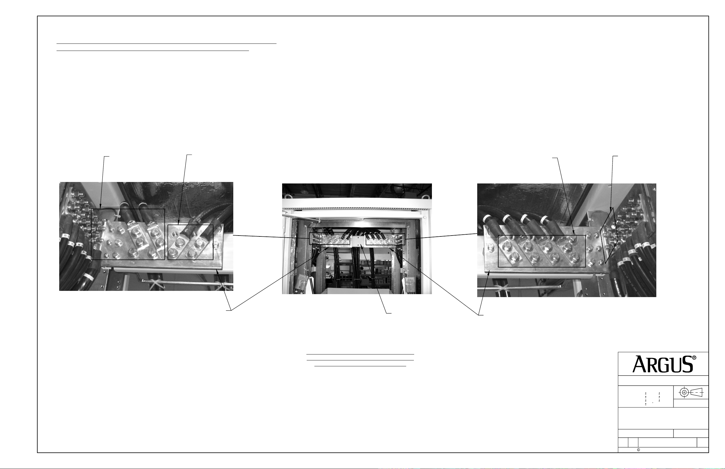
DETAIL B - REAR BATTERY CHARGE TERMINATION
PANEL CABLE ROUTING
CONNECT X2 #4/0 AWG
(-
) CABLES FROM Te41
CONNECT INTERFACE CABLES TO THEIR RESPECTIVE (+) AND (-) BUS BARS ON
CHARGE TERMINATION PANEL USING 3/8" HARDWARE SUPPLIED AS SHOWN.
ENSURE CORRECT POLARITY IS OBSERVED WHEN MAKING CONNECTIONS.
USE A MULTIMETER TO CHECK ALL TERMINATIONS BEFORE
CONNECTING BATTERIES AND APPLYING POWER TO THE SYSTEM.
DETAIL C - FRONT BATTERY CHARGE
TERMINATION PANEL CONNECTIONS
(+24V SYSTEM SHOWN)
BATTERY CHARGE
TERMINATION PANEL
DETAIL D - REAR CABLE ROUTING BETWEEN ENCLOSURES
OBSERVE PROPER BUS POLARITY ON THIS SIDE!
CONNECT X4 #4/0 AWG
(+) CABLES FROM Te41
THESE DESIGNS AND SPECIFICATIONS ARE CONFIDENTIAL, REMAIN
THE PROPERTY OF ALPHA TECHNOLOGIES LTD., AND SHALL NOT
BE COPIED OR USED WITHOUT ITS WRITTEN CONSENT.
UNITS: mm [in]
X [X.X]
X.X [X.XX]
X.XX [X.XXX]
ANGULAR:
TITLE:
CUSTOMER CONNECTION,
KIT, INTERFACE, w/ CBL
SET, PWR TO BATT, Te4x
ISSUE
DATE
TYPE
SIZE
DWG NO.
D2
B
12/27/2009 ALPHA TECHNOLOGIES
1
[ 0.040]
0.5
[ 0.020]
0.05 0.002]
[
0.5
747-602-08
SCALE:
SHEET
NTS
OF
4 5
REV
P/B
Page 44

©
AIR CONDITIONER & AC LOADCENTER AC POWER CONNECTIONS:
©
UTLIITY BOX
Te40 AIR CONDITIONER UTILITY BOX WIRING
CONNECT A SEPARATE POWER CABLE TO THE EXISTING AIR CONDITIONER
AC WIRING INSIDE UTILITY BOX AND ROUTE IT THROUGH BOTH
ENCLOSURES INTO THE Te41 UPPER COMPARTMENT TO THE
INTERNAL AC LOADCENTER.
Te41 UPPER COMPARTMENT INTERNAL AC LOADCENTER WIRING
(ONLY INCLUDED FOR ENCLOSURES NOT EQUIPPED WITH AN EXTERNAL LOADCENTER)
CONNECT THE POWER CABLE COMING FROM Te40 AIR CONDITIONER AC POWER
CONNECTION UTILITY BOX TO A 15A 120VAC RATED 1 POLE FEEDER BREAKER
INSTALLED IN LOADCENTER.
FOR ENCLOSURES WITH AN EXTERNAL LOADCENTER, CONNECT THE POWER CABLE
DIRECTLY TO A 15A 120VAC RATED 1 POLE FEEDER BREAKER INSTALLED IN LOADCENTER.
INTERNAL AC LOADCENTER
Te40 AIR CONDITIONER AC POWER CONNECTION TO Te41
Te41 AC LOADCENTER AIR CONDITIONER
AC POWER CONNECTION FROM Te40
THESE DESIGNS AND SPECIFICATIONS ARE CONFIDENTIAL, REMAIN
THE PROPERTY OF ALPHA TECHNOLOGIES LTD., AND SHALL NOT
BE COPIED OR USED WITHOUT ITS WRITTEN CONSENT.
UNITS: mm [in]
X [X.X]
X.X [X.XX]
X.XX [X.XXX]
ANGULAR:
TITLE:
1
[ 0.040]
0.5
[ 0.020]
0.05 0.002]
0.5
[
SCALE:
NTS
CUSTOMER CONNECTION,
KIT, INTERFACE, w/ CBL
SET, PWR TO BATT, Te4x
ISSUE
DATE
TYPE
SIZE
DWG NO.
D2
B
12/27/2009 ALPHA TECHNOLOGIES
SHEET
747-602-08
OF
5 5
REV
P/B
Page 45

LTR
DESCRIPTION
REVISIONS
DWN
DATE
CHKD
APPD
SIDE KNOCKOUT REMOVAL, PANEL CHANGE
& GASKET INSTALLATION
REMOVE TOP CORNER KNOCKOUTS ON FACING
SIDES OF BOTH ENCLOSURES (2 PER SIDE)
TO ACCEPT BOLTING HARDWARE
REMOVE THE TOP ACCESS BLANK PANEL ON EXISTING
BATTERY ENCLOSURE. INSTALL REPLACEMENT PANEL
(ITEM 5) WITH 4 MOUNTING SCREWS (ITEM 17). MOUNT
PANEL ON INSIDE POSITIONED TOWARDS THE FRONT
WITH OPENING FOR CABLES AT REAR. INSTALL SEALING
GASKET (ITEM 6) AROUND TOP ACCESS OPENING ON
SIDE OF EXISTING BATTERY ENCLOSURE. REMOVE TOP
ACCESS PANEL FROM LEFT SIDE OF 2nd BATTERY
ENCLOSURE.
:
ENCLOSURE SETUP & PREPARATION
CUT AWAY A SMALL SECTION FROM
INNER WALL INSULATION IN THE UPPER
CORNERS OF BOTH ENCLOSURE AS SHOWN
FOR 3/8" HARDWARE INSTALLATION.
A
:
75 [3.0]
64 [2.5]
INSULATION CUT DETAIL
127 5.0
279 11.0
DETAIL A - INSIDE VIEW
DETAIL B - INSIDE VIEW
REMOVE SIDE ACCESS CABLE KNOCKOUTS ON
FACING SIDES OF BOTH ENCLOSURES. INSTALL
SEALING GASKET (ITEM 6) AROUND K.O. OPENINGS
ON SIDE OF EXISTING BATTERY ENCLOSURE.
RIGHT SIDE VIEW
EXISTING BATTERY ENCLOSURE
SHOWN
ALIGN 2nd Te40 BATTERY ENCLOSURE WITH
INSTALLED Te40 BATTERY ENCLOSURE
B
EXISTING Te40 ENCLOSURE
2nd Te40 ENCLOSURE
REAR VIEW
INSULATION CUT DETAIL
DESIGN
DRAWN
CHECKED
APPROVED
413 16.3
EXISTING
CUT LINES
NAME
JK
SDW
JK
ME
CUT AWAY A SMALL SECTION OF INNER
WALL INSULATION IN AREA OF SIDE
ACCESS CABLE KNOCKOUTS ON
BOTH ENCLOSURES AS SHOWN FOR
CHASE NIPPLE INSTALLATION.
THESE DESIGNS AND SPECIFICATIONS ARE CONFIDENTIAL, REMAIN
THE PROPERTY OF ARGUS TECHNOLOGIES LTD., AND SHALL NOT
BE COPIED OR USED WITHOUT ITS WRITTEN CONSENT.
DATE
2009/05
2009/05
2009/06
2009/06
UNITS: mm [in]
X [X.X]
X.X [X.XX]
X.XX [X.XXX]
ANGULAR:
TITLE:
ISSUE
DATE
TYPE
SIZE
B
1
[ 0.040]
0.5
[ 0.020]
0.05
0.5
[ 0.002]
SCALE:
CUSTOMER CONNECTION,
KIT, INTRFC, w/ CBL SET,
BATT TO BATT, Te4x
SHEET
DWG NO.
D2
2009 ARGUS TECHNOLOGIES
747-603-08
ITEM
QTY
NTS
1 7
OF
REV
P/A
Page 46

JOINING OF BATTERY & BATTERY ENCLOSURES
:
3/8" BOLT INSTALLATION
LOCK NUT
14
CABLE TIE-OFF
BAR INSTALLATION
MOUNT IN HOLE #5
(FROM TOP)
4
1
18
2
DETAIL D
NUT
21
2
SEALING
WASHER
20
2
SEALING
WASHER
20219
BOLT
2
18
4
MOUNT IN HOLE #5
(FROM TOP)
2
1
DETAIL C
A
DETAIL A
13
CHASE NIPPLE
2
2
C D
CHASE NIPPLE FITTING
INSTALLATION
DETAIL B
B
REAR VIEW - PANELS REMOVED
THESE DESIGNS AND SPECIFICATIONS ARE CONFIDENTIAL, REMAIN
THE PROPERTY OF ARGUS TECHNOLOGIES LTD., AND SHALL NOT
BE COPIED OR USED WITHOUT ITS WRITTEN CONSENT.
UNITS: mm [in]
X [X.X]
X.X [X.XX]
X.XX [X.XXX]
ANGULAR:
TITLE:
1
[ 0.040]
0.5
[ 0.020]
0.05
0.5
[ 0.002]
SCALE:
CUSTOMER CONNECTION,
KIT, INTRFC, w/ CBL SET,
BATT TO BATT, Te4x
ISSUE
DATE
SIZE
B
TYPE
DWG NO.
D2
2009 ARGUS TECHNOLOGIES
SHEET
747-603-08
NTS
2 7
OF
REV
P/A
Page 47

BATTERY ENCLOSURE (Te40) TO BATTERY ENCLOSURE (Te40)
INTERFACE CABLE ROUTING & CONNECTIONS
:
* SEE NEXT SHEETS FOR FURTHER DETAILS.
A
B
C
D
FRONT VIEW
REAR VIEW
THESE DESIGNS AND SPECIFICATIONS ARE CONFIDENTIAL, REMAIN
THE PROPERTY OF ARGUS TECHNOLOGIES LTD., AND SHALL NOT
BE COPIED OR USED WITHOUT ITS WRITTEN CONSENT.
UNITS: mm [in]
X [X.X]
X.X [X.XX]
X.XX [X.XXX]
ANGULAR:
TITLE:
1
[ 0.040]
0.5
[ 0.020]
0.05
0.5
[ 0.002]
SCALE:
CUSTOMER CONNECTION,
KIT, INTRFC, w/ CBL SET,
BATT TO BATT, Te4x
ISSUE
DATE
SIZE
B
TYPE
DWG NO.
D2
2009 ARGUS TECHNOLOGIES
SHEET
747-603-08
NTS
3 7
OF
REV
P/A
Page 48
BATTERY ENCLOSURE (Te40) TO BATTERY ENCLOSURE (Te40)
INTERFACE CABLE ROUTING & CONNECTIONS CONT'D
EXISITNG Te41 TO Te40
CABLE CONNECTIONS
CONNECT X2 #4/0 AWG
(-) CABLES TO 2ND Te40
:
CONNECT INTERFACE CABLES TO THEIR RESPECTIVE (+) AND (-) BUS BARS ON
CHARGE TERMINATION PANEL USING 3/8" HARDWARE SUPPLIED AS SHOWN.
ENSURE CORRECT POLARITY IS OBSERVED WHEN MAKING CONNECTIONS.
USE A MULTIMETER TO CHECK ALL TERMINATIONS BEFORE CONNECTING
BATTERIES AND APPLYING POWER TO THE SYSTEM.
EXISTING Te41 TO Te40
CABLE CONNECTIONS
CONNECT X2 #4/0 AWG (+) CABLES
(LUGS BACK TO BACK) TO 2nd Te40
OBSERVE PROPER BUS POLARITY ON THIS SIDE!
BATTERY CHARGE
TERMINATION PANEL
DETAIL B - FRONT BATTERY CHARGE
TERMINATION PANEL CONNECTIONS
ON EXISTING Te40 ENCLOSURE
(+24V SYSTEM SHOWN)
OBSERVE PROPER BUS POLARITY ON THIS SIDE!
THESE DESIGNS AND SPECIFICATIONS ARE CONFIDENTIAL, REMAIN
THE PROPERTY OF ARGUS TECHNOLOGIES LTD., AND SHALL NOT
BE COPIED OR USED WITHOUT ITS WRITTEN CONSENT.
UNITS: mm [in]
X [X.X]
X.X [X.XX]
X.XX [X.XXX]
ANGULAR:
TITLE:
1
[ 0.040]
0.5
[ 0.020]
0.05
0.5
[ 0.002]
SCALE:
CUSTOMER CONNECTION,
KIT, INTRFC, w/ CBL SET,
BATT TO BATT, Te4x
ISSUE
DATE
SIZE
B
TYPE
DWG NO.
D2
2009 ARGUS TECHNOLOGIES
SHEET
747-603-08
NTS
4 7
OF
REV
P/A
Page 49

BATTERY ENCLOSURE (Te40) TO BATTERY ENCLOSURE (Te40)
INTERFACE CABLE ROUTING & CONNECTIONS CONT'D
CONNECT X2 #4/0 AWG
(-) CABLES
:
CONNECT INTERFACE CABLES TO THEIR RESPECTIVE (+) AND (-) BUS BARS ON
CHARGE TERMINATION PANEL USING 3/8" HARDWARE SUPPLIED AS SHOWN.
ENSURE CORRECT POLARITY IS OBSERVED WHEN MAKING CONNECTIONS.
USE A MULTIMETER TO CHECK ALL TERMINATIONS BEFORE CONNECTING
BATTERIES AND APPLYING POWER TO THE SYSTEM.
CONNECT X2 #4/0 AWG
(+) CABLES
OBSERVE PROPER BUS POLARITY ON THIS SIDE!
BATTERY CHARGE
TERMINATION PANEL
DETAIL A - FRONT BATTERY CHARGE
TERMINATION PANEL CONNECTIONS
ON 2nd Te40 ENCLOSURE
(+24V SYSTEM SHOWN)
OBSERVE PROPER BUS POLARITY ON THIS SIDE!
THESE DESIGNS AND SPECIFICATIONS ARE CONFIDENTIAL, REMAIN
THE PROPERTY OF ARGUS TECHNOLOGIES LTD., AND SHALL NOT
BE COPIED OR USED WITHOUT ITS WRITTEN CONSENT.
UNITS: mm [in]
X [X.X]
X.X [X.XX]
X.XX [X.XXX]
ANGULAR:
TITLE:
1
[ 0.040]
0.5
[ 0.020]
0.05
0.5
[ 0.002]
SCALE:
CUSTOMER CONNECTION,
KIT, INTRFC, w/ CBL SET,
BATT TO BATT, Te4x
ISSUE
DATE
SIZE
B
TYPE
DWG NO.
D2
2009 ARGUS TECHNOLOGIES
SHEET
747-603-08
NTS
5 7
OF
REV
P/A
Page 50

BATTERY ENCLOSURE (Te40) TO BATTERY ENCLOSURE (Te40)
INTERFACE CABLE ROUTING & CONNECTIONS CONT'D
:
CABLE TIE-OFF
BAR
NEATLY STRAP INTERFACE CABLES
TO TIE-OFF BAR USING CABLE TIES
(ITEM 36 & 37) PROVIDED IN KIT.
ROUTE INTERFACE CABLES FROM EXISTING
Te40 ENCLOSURE CHARGE TERMINATION PANEL
THROUGH CHASE NIPPLE FITTINGS TO 2nd Te40
ENCLOSURE CHARGE TERMINATION PANEL
AS SHOWN.
2nd Te40 ENCLOSURE
EXISTING Te40 ENCLOSURE
DETAIL C - REAR BATTERY CHARGE TERMINATION PANEL
CABLE ROUTING (TYP.)
DETAIL D - REAR BATTERY INTERFACE
CABLE ROUTING
THESE DESIGNS AND SPECIFICATIONS ARE CONFIDENTIAL, REMAIN
THE PROPERTY OF ARGUS TECHNOLOGIES LTD., AND SHALL NOT
BE COPIED OR USED WITHOUT ITS WRITTEN CONSENT.
UNITS: mm [in]
X [X.X]
X.X [X.XX]
X.XX [X.XXX]
ANGULAR:
TITLE:
1
[ 0.040]
0.5
[ 0.020]
0.05
0.5
[ 0.002]
SCALE:
CUSTOMER CONNECTION,
KIT, INTRFC, w/ CBL SET,
BATT TO BATT, Te4x
ISSUE
DATE
SIZE
B
TYPE
DWG NO.
D2
2009 ARGUS TECHNOLOGIES
SHEET
747-603-08
NTS
6 7
OF
REV
P/A
Page 51

AIR CONDITIONER AC POWER CONNECTION
UTLIITY BOX
:
Te40 AIR CONDITIONER UTILITY BOX WIRING
CONNECT A SEPARATE POWER CABLE TO THE EXISTING AIR CONDITIONER
AC WIRING INSIDE THE UTILITY BOX AND ROUTE IT OUT THROUGH
THE ENCLOSURE(S) TO A SEPARATE AC POWER SUPPLY FEED.
NOTE
:
THE AIR CONDITIONER UNIT MUST BE SUPPLIED FROM A SEPARATE
AC SOURCE PROTECTED BY A 15A 120VAC RATED 1 POLE CIRCUIT BREAKER
AHEAD OF IT.
THIS CONNECTION CAN ALSO BE MADE TO THE OPTIONAL EXTERNAL
AC LOADCENTER ON THE Te41 POWER ENCLOSURE IF INSTALLED.
Te40 AIR CONDITIONER AC POWER WIRING
THESE DESIGNS AND SPECIFICATIONS ARE CONFIDENTIAL, REMAIN
THE PROPERTY OF ARGUS TECHNOLOGIES LTD., AND SHALL NOT
BE COPIED OR USED WITHOUT ITS WRITTEN CONSENT.
UNITS: mm [in]
X [X.X]
X.X [X.XX]
X.XX [X.XXX]
ANGULAR:
TITLE:
1
[ 0.040]
0.5
[ 0.020]
0.05
0.5
[ 0.002]
SCALE:
CUSTOMER CONNECTION,
KIT, INTRFC, w/ CBL SET,
BATT TO BATT, Te4x
ISSUE
DATE
SIZE
B
TYPE
DWG NO.
D2
2009 ARGUS TECHNOLOGIES
SHEET
747-603-08
NTS
7 7
OF
REV
P/A
Page 52

©
76 3.0
©
4 18
1
MOUNT IN HOLE #5
FROM TOP
2
POWER AND BATTERY ENCLOSURE
SETUP & PREPARATION
PREPARATION OF BATTERY ENCLOSURE Te40:
SIDE KNOCKOUT REMOVAL, PANEL CHANGE, INSULATION
CUTOUT & TIE-OFF BAR INSTALLATION
CUT AWAY A SMALL SECTION FROM
INNER WALL INSULATION IN THE UPPER
CORNERS OF BOTH ENCLOSURES AS SHOWN
FOR 3/8" HARDWARE INSTALLATION.
REMOVE TOP CORNER KNOCKOUTS ON FACING
SIDES OF BOTH ENCLOSURES (2 PER SIDE)
REMOVE EXISTING TOP ACCESS BLANK PANEL ON
BATTERY ENCLOSURE. INSTALL REPLACEMENT PANEL
(ITEM 5) WITH 4 MOUNTING SCREWS (ITEM 17). MOUNT
PANEL ON INSIDE POSITIONED TOWARDS THE FRONT
WITH OPENING FOR CABLES AT REAR.
DESCRIPTIONLTR APPDDATEDWN CHKD
ADD TE21 INSTALLATIONA
TO ACCEPT BOLTING HARDWARE
REVISIONS
ME10/04KL JK
BATTERY ENCLOSURE
REAR VIEW - PANELS REMOVED
KO REQUIRE TO BE REMOVED
MAY BE LOCATED ON THE
OTHER SIDE DEPENDING ON THE
ENCLOSURE CONFIGURATION
64 2.5
5.0127
279 11.0
396 15.6
EXISTING
CUT LINES
INSULATION CUT DETAIL
CUT AWAY A SMALL SECTION OF INNER
WALL INSULATION IN AREA OF SIDE
ACCESS CABLE KNOCKOUTS ON
INSIDE OF BOTH ENCLOSURES FOR
CHASE NIPPLE INSTALLATION.
INSULATION CUT DETAIL
NOTE: ONLY REMOVE KNOCK OUTS ON
FACING SIDE OF BATTERY ENCLOSURE
REMOVE SIDE ACCESS CABLE KNOCKOUTS ON
FACING SIDE OF BATTERY ENCLOSURE ONLY.
NAME DATE
DESIGN 2009/05
DRAWN
CHECKED
APPROVED
JK
SDW
JK
ME
2009/05
2009/06
2009/06
THESE DESIGNS AND SPECIFICATIONS ARE CONFIDENTIAL, REMAIN
THE PROPERTY OF ALPHA TECHNOLOGIES LTD., AND SHALL NOT
BE COPIED OR USED WITHOUT ITS WRITTEN CONSENT.
UNITS: mm [in]
X [X.X]
X.X [X.XX]
X.XX [X.XXX]
ANGULAR:
TITLE:
1
[ 0.040]
0.5
[ 0.020]
0.05 0.002]
0.5
[
SCALE:
CUSTOMER CONNECTION,
KIT, INTERFACE, w/o CBL
SET, PWR TO BATT, Te4x
ISSUE
DATE
TYPE
SIZE
DWG NO.
D2
B
4/30/2009 ALPHA TECHNOLOGIES
SHEET
747-607-08
ITEM
QTY
NTS
OF
1 3
REV
A
Page 53

©
PREPARATION OF POWER ENCLOSURE Te41:
©
GASKET INSTALLATION, KNOCK OUT REMOVAL
NOTE: ONLY REMOVE KNOCK OUTS ON FACING
SIDE OF POWER ENCLOSURE
REMOVE TOP CORNER
KNOCKOUTS ON FACING
SIDES OF BOTH
ENCLOSURES (2 PER SIDE)
TO ACCEPT BOLTING
HARDWARE.
REMOVE EXISTING TOP
ACCESS BLANK PANEL ON
POWER ENCLOSURE.
INSTALL SEALING
GASKET (ITEM 6) AROUND
TOP ACCESS OPENING ON
POWER ENCLOSURE SIDE
ONLY.
POWER AND BATTERY ENCLOSURE
SETUP & PREPARATION
JOINING OF POWER (Te41) &
BATTERY (Te40) ENCLOSURES:
21
20
1
1
2 PL
20
19
1
1
RIGHT SIDE VIEW
POWER ENCLOSURE SHOWN
KNOCK OUTS REQUIRED TO BE
REMOVED MAY BE LOCATED ON THE
LEFT SIDE PANEL DEPENDING ON THE
ENCLOSURE CONFIGURATION
REMOVE SIDE ACCESS CABLE
KNOCKOUTS AND CUT AWAY A SMALL
SECTION OF INNER WALL INSULATION
IN AREA OF SIDE ACCESS CABLE
KNOCKOUTS ON FACING SIDE OF
POWER ENCLOSURE FOR CHASE
NIPPLE INSTALLATION.
INSTALL SEALING GASKET (ITEM 6)
AROUND K.O. OPENINGS ON POWER
ENCLOSURE SIDE ONLY.
MOVE BATTERY ENCLOSURE INTO
POSITION LINING UP NEXT TO
POWER ENCLOSURE
BATTERY ENCLOSURE
(MAY BE LOCATED ON THE OTHER
SIDE OF POWER ENCLOSURE
DEPENDING ON CONFIGURATION)
REAR VIEW
POWER ENCLOSURE
14
1
THESE DESIGNS AND SPECIFICATIONS ARE CONFIDENTIAL, REMAIN
THE PROPERTY OF ALPHA TECHNOLOGIES LTD., AND SHALL NOT
BE COPIED OR USED WITHOUT ITS WRITTEN CONSENT.
UNITS: mm [in]
X [X.X]
X.X [X.XX]
X.XX [X.XXX]
ANGULAR:
TITLE:
1
[ 0.040]
0.5
[ 0.020]
0.05 0.002]
0.5
[
SCALE:
CUSTOMER CONNECTION,
KIT, INTERFACE, w/o CBL
SET, PWR TO BATT, Te4x
ISSUE
DATE
TYPE
SIZE
DWG NO.
D2
B
4/30/2009 ALPHA TECHNOLOGIES
SHEET
747-607-08
13
1
NTS
OF
2 3
REV
A
Page 54

©
PREPARATION OF POWER ENCLOSURE Te21:
©
GASKET INSTALLATION, KNOCK OUT & PANEL REMOVAL
NOTE: ONLY REMOVE KNOCK OUTS & PANEL ON FACING
SIDE OF POWER ENCLOSURE
REMOVE TOP CORNER
KNOCKOUTS ON FACING
SIDES OF BOTH
ENCLOSURES (2 PER SIDE)
TO ACCEPT BOLTING
HARDWARE.
REMOVE EXISTING TOP
ACCESS BLANK PANEL ON
POWER ENCLOSURE.
INSTALL SEALING
GASKET (ITEM 9) AROUND
TOP ACCESS OPENING ON
POWER ENCLOSURE SIDE
ONLY.
POWER AND BATTERY ENCLOSURE
SETUP & PREPARATION
20
21
1
1
2 PL
JOINING OF POWER (Te21) &
BATTERY (Te40) ENCLOSURES:
20
19
1
1
INSTALL GROMMET
(ITEM 16) AROUND
REMOVED KO ON
BATTERY
ENCLOSURE
RIGHT SIDE VIEW
POWER ENCLOSURE SHOWN
KNOCK OUTS REQUIRED TO BE
REMOVED MAY BE LOCATED ON THE
LEFT SIDE PANEL DEPENDING ON THE
ENCLOSURE CONFIGURATION
REMOVE SIDE ACCESS CABLE
KNOCKOUTS PANEL ON
FACING SIDES OF POWER
ENCLOSURE.
INSTALL SEALING GASKET
(ITEM 8) AROUND
PANEL OPENINGS ON POWER
ENCLOSURE SIDE ONLY.
REAR PANEL REMOVED
MOVE BATTERY ENCLOSURE INTO
POSITION LINING UP NEXT TO
POWER ENCLOSURE
22833831
8
Te 21 BATTERY TERMINATION
ADAPTER BARS INSTALLATION
7
33231219
1
2
POWER ENCLOSURE
BATTERY ENCLOSURE
(MAY BE LOCATED ON THE OTHER
SIDE OF POWER ENCLOSURE
DEPENDING ON CONFIGURATION)
REAR VIEW
THESE DESIGNS AND SPECIFICATIONS ARE CONFIDENTIAL, REMAIN
THE PROPERTY OF ALPHA TECHNOLOGIES LTD., AND SHALL NOT
BE COPIED OR USED WITHOUT ITS WRITTEN CONSENT.
UNITS: mm [in]
X [X.X]
X.X [X.XX]
X.XX [X.XXX]
ANGULAR:
TITLE:
1
[ 0.040]
0.5
[ 0.020]
0.05 0.002]
[
0.5
CUSTOMER CONNECTION,
KIT, INTERFACE, w/o CBL
SET, PWR TO BATT, Te4x
ISSUE
DATE
TYPE
SIZE
DWG NO.
D2
B
4/30/2009 ALPHA TECHNOLOGIES
747-607-08
SCALE:
SHEET
NTS
OF
3 3
REV
A
Page 55

LTR
DESCRIPTION
REVISIONS
DWN
DATE
CHKD
APPD
5
1
14
1
2PL
9
1
1
1
14
1
6PL
29
18
1
1
6PL
ARGUS Te4x POWER SYSTEM
29
18
1
1
6PL
ITEM
QTY
THESE DESIGNS AND SPECIFICATIONS ARE CONFIDENTIAL, REMAIN
THE PROPERTY OF ARGUS TECHNOLOGIES LTD., AND SHALL NOT
BE COPIED OR USED WITHOUT ITS WRITTEN CONSENT.
DATE
2009/05
2009/05
2009/05
2009/05
UNITS: mm [in]
X [X.X]
X.X [X.XX]
X.XX [X.XXX]
ANGULAR:
TITLE:
1
[ 0.040]
0.5
[ 0.020]
0.05
0.5
[ 0.002]
SCALE:
KIT, BRIDGE INTERFACE,
NOKIA, Te4x
ISSUE
DATE
TYPE
SIZE
DWG NO.
D2
B
5/21/2009 ARGUS TECHNOLOGIES
SHEET
747-595-08
NTS
1 1
OF
REV
P/A
NOKIA CABINET UPPER SECTION
DESIGN
DRAWN
CHECKED
APPROVED
NAME
RP
KL
RP
JK
Page 56

©
DESCRIPTIONLTR APPDDATEDWN CHKD
©
REDESIGNEDP/B
ADD 5, 6, UPDATE 1, 2P/C
REVISIONS
RP09/06KL JK
RP09/09KL JK
3/8" HEX SCREW
PART OF ITEM 2
3/8" SEAL WASHER
PART OF ITEM 2
STEP #1
65
1
1
3/8" SEAL WASHER
PART OF ITEM 2
3/8" NUT
PART OF ITEM 2
GASKETS (ITEM 5 & 6) MUST INTERLOCK
WHEN ADHERE TO THE BOTTOM OF TOP
EXTENSION AS SHOWN AT 4 PLACES
4 PL
STEP #2
NOTE: INSTALL HATCH PLATE BEFORE
TOP EXTENSION AS HATCH PLATE IS NOT
REMOVABLE WITH TOP EXTENSION INSTALLED
STEP #5
ITEM
QTY
THESE DESIGNS AND SPECIFICATIONS ARE CONFIDENTIAL, REMAIN
THE PROPERTY OF ARGUS TECHNOLOGIES LTD., AND SHALL NOT
BE COPIED OR USED WITHOUT ITS WRITTEN CONSENT.
UNITS: mm [in]
X [X.X]
X.X [X.XX]
X.XX [X.XXX]
ANGULAR:
TITLE:
NAME DATE
1
STEP #3
1
2
STEP #4
1
DESIGN 2009/05
DRAWN
CHECKED
APPROVED
RP
RP
SY
JK
2009/05
2009/05
2009/05
ISSUE
DATE
SIZE
B
TYPE
1
[ 0.040]
0.5
[ 0.020]
0.05 0.002]
0.5
[
SCALE:
DWG, ASSY SEQUENCE,
TOP EXTENSION, 9",
ENCLR
SHEET
1 1
DWG NO.
D2
6/17/2009 ARGUS TECHNOLOGIES
747-531-F0
NTS
OF
REV
P/C
Page 57

©
KIT, PLINTH,
W/ MOUNTING HARDWARE,
ITEM
©
PART
NO.
NUMBER
1 615-311-R8
5 634-092-10
9 633-159-10
10 633-615-10
14 631-170-10
20 570-026-10
DESCRIPTION QTY.
ASSY, PLINTH, 30"X30",
STL, EXT GRAY
Nut,1/2"-13,Hex,3/4"
AF,7/16" Thk,SSt
WASHER, LOCK, HELICAL
SPRING, 1/2" BOLT, SST
WASHER, FLAT, 1/2", 1.25"
OD, 0.084"THK, SST
SCREW, CAP, 1/2-13X2",
HEXHEAD, SST
PLUG, PLINTH END, 6"X4",
PLASTIC
DESCRIPTIONLTR APPDDATEDWN CHKD
1
4
4
8
4
4
1410
9
1
1
1
REVISIONS
4 PL
20
1
4 PL
10
1
4 PL
ITEM
QTY
THESE DESIGNS AND SPECIFICATIONS ARE CONFIDENTIAL, REMAIN
THE PROPERTY OF ALPHA TECHNOLOGIES LTD., AND SHALL NOT
BE COPIED OR USED WITHOUT ITS WRITTEN CONSENT.
2010/01
2010/01
2010/01
UNITS: mm [in]
X [X.X]
X.X [X.XX]
X.XX [X.XXX]
ANGULAR:
TITLE:
1
[ 0.040]
0.5
[ 0.020]
0.05 0.002]
[
0.5
4"H X 30" W X 30"D
ISSUE
DATE
TYPE
SIZE
DWG NO.
D2
B
1/20/2010 ALPHA TECHNOLOGIES
SCALE:
SHEET
1 1
747-592-F0
NTS
OF
REV
A
5
1
1
1
DESIGN 2010/01
DRAWN
CHECKED
APPROVED
NAME DATE
JK
KL
RP
JK
Page 58

7.06
LTR
DESCRIPTION
REVISIONS
DWN
DATE
CHKD
APPD
120.5
4.74
214.8
8.46
425.3 16.74
0
179.2
389.7 15.34
484.0 19.06
0
7
REF. 615-360-C8/PA
16
A
A
A
A
A
A
A
A
6
16
5
16
A
A
A
A
519.6 20.46
A A
HOLES LOCATION
A A
1
4
2
4
DESIGN
DRAWN
CHECKED
APPROVED
NAME
DX
DX
RP
JK
DATE
2009/06
2009/06
2009/06
2009/06
4.9 [0.19] 16
A
LTR
THESE DESIGNS AND SPECIFICATIONS ARE CONFIDENTIAL, REMAIN
THE PROPERTY OF ARGUS TECHNOLOGIES LTD., AND SHALL NOT
BE COPIED OR USED WITHOUT ITS WRITTEN CONSENT.
UNITS: mm [in]
X [X.X]
X.X [X.XX]
X.XX [X.XXX]
ANGULAR:
TITLE:
KIT,4X CABLE BOOT,TOP
DESCRIPTION
FINISHED HOLE LEGEND
1
[ 0.040]
0.5
[ 0.020]
0.05
0.5
[ 0.002]
SCALE:
EXT,TE4X
ISSUE
DATE
SIZE
B
TYPE
DWG NO.
D2
2009 ARGUS TECHNOLOGIES
SHEET
747-627-F0
NTS
1 1
OF
REV
P/A
QTY
Page 59

Warranty
Alpha Technologies Limited (ATL) warrants its products to be free from defects in material and workmanship
for a period of two (2) years from the date of purchase. ATL obligation under this warranty is limited to the
repair or replacement, at its sole discretion, at the ATL factory or ATL Authorized Service Center, of any defective product. This warranty does not cover any failure of the unit caused in whole or in part by any cause
or causes external to the unit. Repair or replacement does not extend the original warranty period. Parts
furnished under this warranty may be new or factory-remanufactured.
Registration
This warranty is only available to the original end user of the product. Registering the product will automatically increase the length of the original warranty by 3 months at no additional cost. Please register your product
online at www.alpha.com/productregistration.
Extended Warranty
Registered purchasers may extend the warranty period for up to 3 additional years at any time during the
original warranty period at the then prevailing rate of ATL for such warranty extension. Registered purchasers
may be eligible to purchase other units, accessories, parts or services at discounted rates, including battery
upgrade or replacement, during the coverage period. Please contact us at 1-800-667-8743 to discuss your
service needs.
Limitation of Liability
This warranty is the purchaser’s sole remedy and is expressly in lieu of any other warranty, expressed or
implied, including any implied warranty of merchantability or fi tness for purpose.
In no event shall ATL be liable for any indirect, incidental, special or consequential damages. In no case will
the liability of ATL under this warranty exceed the value of the unit provided.
Page 60

Alpha Technologies Ltd.
7700 Riverfront Gate
Burnaby, BC V5J 5M4
Canada
Tel: +1 604 436 5900
Fax: +1 604 436 1233
Toll Free: +1 800 667 8743
Alpha Technologies Inc.
3767 Alpha Way
Bellingham, WA 98226
United States
Tel: +1 360 647 2360
Fax: +1 360 671 4936
Alpha Industrial Power Inc.
1075 Satellite Blvd NW,
Suite 400
Suwanee, GA 30024
United States
Tel: +1 678 475 3995
Fax: +1 678 584 9259
Alpha Energy
1628 W Williams Drive
Phoenix, AZ 85027
United States
Tel: +1 602 997 1007
Fax: +1 623 249 7833
Alpha Technologies Europe Ltd.
Twyford House Thorley
Bishop’s Stortford
Hertfordshire, CM22 7PA
United Kingdom
Tel: +44 1279 501110
Fax: +44 1279 659870
Alpha Technologies
Unit 504, 5/F,
Fourseas Building
No 208-212 Nathan
Road
Kowloon, Hong Kong
Tel: +852 2736 8663
Fax: +852 2199 7988
Alpha Technologies GmbH
Hansastrasse 8
D-91126
Schwabach, Germany
Tel: +49 9122 79889 0
Fax: +49 9122 79889 21
Alphatec Ltd.
339 St. Andrews St.
Suite 101 Andrea Chambers
P.O. Box 56468
3307 Limassol, Cyprus
Tel: +357 25 375 675
Fax: +357 25 359 595
Alpha Inno
vations Brasil
Avenida Ibirapuera,
2120 – Cj 76
Moema - 04028-001
Santos S P, Brazil
Tel: +55 11 2476 0150
Fax: +55 11 2476 0150
Technologies Argus
First de Mexico
Anatole France Num. 17
Colonia Polanco
11560, México D.F.
Tel: +52 55 5280 6990
Alpha TEK ooo
Khokhlovskiy Pereulok 16
Stroenie 1, Office 403
Moscow, 109028
Russia
Tel: +7 495 916 1854
Fax: +7 495 916 1349
Alphatec Baltic
S. Konarskio Street 49-201
Vilnius, LT-03123
Lithuania
Tel: +370 5 210 5291
Fax: +370 5 210 5292
Visit us at www.alpha.ca
Due to continuing product development, Alpha Technologies reserves the right to change specifications without notice.
Copyright © 2010 Alpha Technologies. All Rights Reserved. Alpha® is a registered trademark of Alpha Technologies.
 Loading...