

Page 1
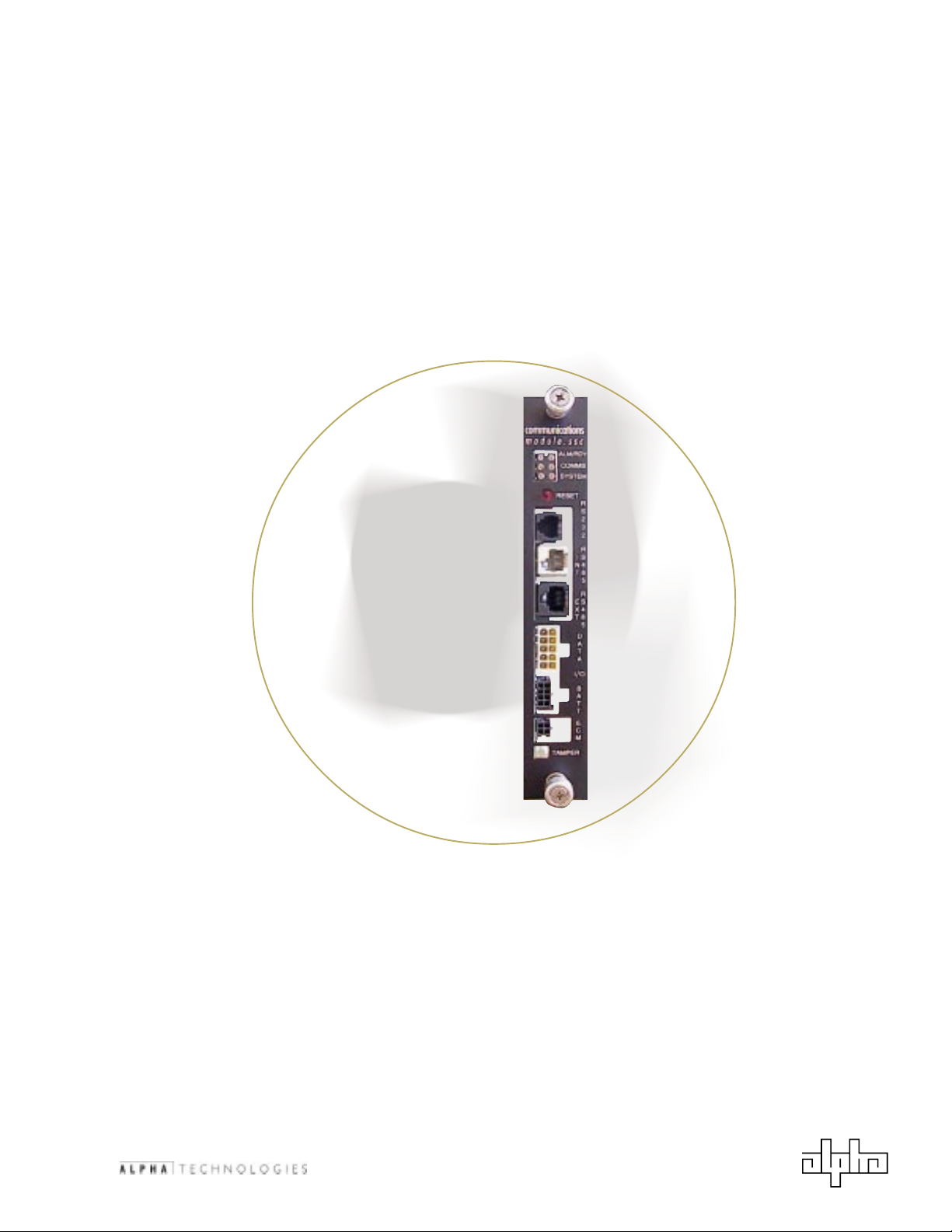
Serial System Controller
© 2001
Operation and Maintenance Manual
Effective: January, 2001
®
TM
Page 2

018-332-C0-002 Rev. B
2
© 2001
TM
Page 3
®
Serial System
Controller
Operation and Maintenance Manual
018-332-C0-002, Rev. B
January, 2001
© 2001 Alpha Technologies
Overview: The purpose of the Serial System Controller
Operation and Maintenance Manual is to detail
system features, installation, operation, and
maintenance procedures. It is written primarily
for the system operator.
NOTE: Alpha Technologies products are subject to change through
continual improvement processes. Therefore, specifications
and/or design layouts may vary slightly from descriptions
included in this manual. Updates to the manual will be issued
when changes affect form, fit or function.
Keep these instructions for future reference.
© 2001
TM
3 018-332-C0-002 Rev. B
Page 4

Serial System Controller
Product Safety ................................................................. 6
Important Safety Instructions Contained in this Manual .............................. 6
Safety Precautions ............................................................................... 7
Battery Safety Notes ............................................................................ 7
Contact Alpha .................................................................. 8
1. System Overview
1.1 Theory of Operation ...................................................................... 9
1.1.1 Battery Charging............................................................... 9
1.1.2 System Self-Test .............................................................10
1.1.3 Low battery Shutdown of Inverters ....................................11
1.1.4 Enclosure Monitoring ........................................................11
Table of Contents
1.2 Indicators & Connections.............................................................. 12
1.2.1 Front Panel Layout, Serial System Controller (SSC) .............. 12
1.2.2 Diagram: The SSC in a Power System ................................ 13
1.2.3 LED Indicators ................................................................ 14
1.2.4 Reset Switch.................................................................. 14
1.2.5 Serial Communications Interfaces ...................................... 15
1.2.5.1 Internal RS-485 ....................................................... 15
1.2.5.2 External RS-485 ...................................................... 15
1.2.5.3 External RS-232 ...................................................... 15
1.2.5.4 ECM Port................................................................ 16
1.2.6 SSC/Power Supply Interconnection .................................... 17
1.2.7 Data I/O Port ................................................................. 18
1.2.8 Battery Connection Port................................................... 20
1.2.9 Tamper .......................................................................... 21
1.3 Dip Switch: Switch 1 ................................................................... 22
2. Installation
2.1 Module Conversion....................................................................... 23
2.2 SSC Installation .......................................................................... 25
2.3 System Configuration ................................................................... 26
018-332-C0-002 Rev. B
2.4 Smart Display Setup Menu ............................................................ 27
3. Alarms
3.1 Alarm LEDs ................................................................................. 28
4
© 2001
TM
Page 5

Serial System Controller
Table of Figures
Figure 1-1; Alpha Technologies Serial System Controller (SSC) ................ 12
Figure 1-2; Basic Diagram: SSC Shown in Power System......................... 13
Figure 1-3; LED Block, Reset Switch .................................................... 14
Figure 1-4; RS-232 and Alpha/HMS Bus RS-485 Connectors .................... 15
Figure 1-5; ECM Port on SSC.............................................................. 16
Figure 1-6; ECM COMM Port ............................................................... 16
Figure 1-7; Configuration for Multiple Power Supplies ............................. 17
Figure 1-8; Data I/O Connector .......................................................... 18
Figure 1-9; Battery Connector ............................................................ 20
Figure 1-10; Battery Schematic ........................................................... 20
Figure 1-11; Tamper Switch Pin Arrangement.......................................... 21
Figure 1-12; Switch 1 - Configuration Switch......................................... 22
Figure 2-1; Location of Communications Module in XM2 Power Supply ....... 23
Figure 2-2; Preparing Inverter Module to Receive SSC ............................ 24
Figure 2-3; Inverter Module with SSC Installed ..................................... 25
List of Tables
Table 1-1; Digital Inputs and Outputs ................................................. 18
Table 3-1; Alarm LEDs ...................................................................... 28
© 2001
TM
5 018-332-C0-002 Rev. B
Page 6
Product Safety
Safety Symbols Used in this Manual
Caution
Hazardous Condition
To reduce the risk of electrical shock, injury or death caused by
explosion of fuel or moving parts, and to ensure the safe operation of
this unit, the following symbols have been placed throughout the
manual. Where these symbols appear, servicing must be performed
only by qualified personnel.
Dangerous Voltage
This symbol indicates a dangerous voltage exists in this area
of the product. Use caution whenever working in the area to
prevent electrical shock.
Attention
This symbol indicates important installation, operation or
maintenance instructions. Always follow these instructions
closely.
018-332-C0-002 Rev. B
6
© 2001
TM
Page 7

Product Safety
Safety Precautions
The Serial System Controller (SSC) must be serviced only by
qualified personnel.
Remove all rings, watches and other jewelry before servicing
batteries or installing the SSC.
Verify the voltage requirements of the equipment to be protected
(load), the AC input voltage to the power supply (line), and the
output voltage of the system prior to installation.
The utility service panel must be equipped with a properly rated
circuit breaker for use with this power supply.
When connecting the load, DO NOT exceed the output rating of
the system.
Always use proper lifting techniques whenever handling units,
modules or batteries.
Battery Safety Notes
Chemical Hazards
Any gelled or liquid emissions from a Valve-Regulated Lead-Acid (VRLA) battery
is electrolyte which contains dilute sulfuric acid which is harmful to the skin
and eyes; is electrically conductive; and is corrosive. If electrolyte contacts
the skin, wash immediately and thoroughly with water. If electrolyte enters
the eyes, wash thoroughly for 10 minutes with clean water or a special
neutralizing eye wash solution and seek immediate medical attention.
Neutralize any spilled electrolyte with the special solutions contained in a spill
kit or with a solution of 1 lb. Bicarbonate of soda to 1 gallon of water.
Fire, Explosion, and Heat Hazards
Lead acid batteries can contain an explosive mixture of hydrogen gas which
can vent under overcharging conditions. Do not smoke or introduce sparks in
the vicinity of the battery. Prior to handling the batteries, touch a grounded
metal object, such as the rack, to dissipate any static charge that may have
developed in your body. Do not charge batteries in a sealed container. The
individual batteries should have 0.5 inches of space between them to allow for
convection cooling. If contained, assure the container or cabinet and room
have adequate ventilation to prevent an accumulation of potentially dangerous
gas.
© 2001
TM
7
018-332-C0-002 Rev. B
Page 8

Contact Alpha
Contact Information
General product information
and customer service
7:00 AM to 5:00 PM Pacific Time
1-800-863-3930
To obtain complete technical support
7:00 AM to 5:00 PM Pacific Time
or
For after-hours emergency support
7 days per week, 24 hours a day
1-800-863-3364
Instructions for Returns
Returns for Repair
For units that must be returned for repair, Alpha requires a Return Material Authorization
(RMA). An RMA can be obtained from Alpha Customer Service, using either method listed
below:
Download the necessary forms directly from Alpha's Web site, under "Customer
Service": www.alpha.com
Or call (800) 322-5742 for assistance.
Clearly mark the RMA on the units original shipping container. If the original container is not
available, make sure the unit is packed with at least three inches of shock absorbing
material to prevent shipping damage.
NOTE: Do not use popcorn-type material. Alpha Technologies is not responsible
for damage caused by improper packing on returned units.
In addition to the returned unit, please include a copy of the power supply maintenance log
and any information relevant to the power supply failure.
Returns for Credit
For returns for credit, call (800) 322-5742.
© 2001
TM
8
017-900-B0-001 Rev. A
Page 9
1. System Overview
1.1 Theory of Operation
The Serial System Controller (SSC) manages and provides status monitoring for powering
systems that contain single or multiple (up to six) power supplies, and a generator. It
coordinates battery charging, individual battery monitoring, and self-testing for individual
components in the system. Using a serial interface, Alphas Engine Control Module (ECM)
communicates with the SSC to manage generator operation.
The SSC coordinates the following control functions of the power supply system:
Battery charging
System self-test
Low battery shutdown of inverters
Initiation of low battery disconnect
Monitoring of system configuration
Battery temperature monitoring
Acquisition and maintenance of data from all units in the system
Response to queries from a digital transponder
Monitoring of individual battery voltage
Maintenance of critical parameters in nonvolatile memory
Four user-defined discrete outputs, one input
SSC to serial transponder communication supports: HMS022 for individual power supplies;
HMS022 for the generator system; Alpha power system status; Alpha individual power supply
and extended status; and Alpha generator configuration and extended status.
NOTE: XM2 power supplies must have firmware 3.01 or higher for SSC to
operate.
1.1.1 Battery Charging
Each XM2 has a battery charger capable of delivering a maximum current to the
battery string. XM2s in a system configuration typically share a single string of
batteries, and each provides its maximum charging current to the string after a major
discharge event. Since this may damage the batteries, the SSC determines the
number of power supplies in the system, and limits the individual power supply
chargers so that the maximum charging current is never exceeded. The maximum
charging current for a battery string can be calculated by using the following formula:
Maximum Charging Current <= (Battery Capacity / 5)
For example, total charger current of 100 Amp Hour batteries cannot exceed 20
Amps. If a system contains five power supplies, each will be limited to 4 Amps
maximum.
© 2001
The SSC waits for a unit in the system to transition into FLOAT mode, then watches
system charging current drop below a threshold, based on the number of power
supplies in the system. It then forces all of the XM2 power supplies into FLOAT mode
to complete the battery charge.
TM
9
018-332-C0-002 Rev. B
Page 10

1. System Overview
1.1 Theory of Operation, continued
1.1.2 System Self-Test
System self-test is either initiated by expiration of the Auto Test Countdown timer, or
by asserting the Self-Test switch via the digital transponder interface.
Prior to the test sequence, the SSC will:
Verify that all XM2s are operating in line mode
Check the battery capacity and number of strings
Query the XM2 General Status alarms
The test will not run if:
Any power supply is in standby mode when the self-test begins
Either the battery capacity or number of strings has been programmed
to zero
Any power supply alarm is active
After the above conditions have been met, the SSC will begin the test sequence.
During the test, the SSC will:
Disable all battery chargers
Initiate a self-test in a single power supply
Note: Each XM2 auto-test runs to completion before the SSC requests self-
test of the next power supply. Each XM2 in the system is cycled
through its test sequence. If any XM2 reports self-test failure, the
device address of that unit will be reported in the SSC Test Failed
alarm.
Checks to see if a generator is installed in the system (when switch #3
is in the ON position)
Asks the SSC to run a self-test of the engine generator (when switch
#3 is in the ON position)
Turns all battery chargers back on
Test duration is programmed into each XM2 by the SSC. When the Auto-Test Interval
in the master XM2 is reprogrammed, the new value will be detected by the SSC,
which in turn will reprogram all other XM2s in the system.
018-332-C0-002 Rev. B
10
© 2001
TM
Page 11

1.1 Theory of Operation, continued
1.1.3 Low battery Shutdown of Inverters
Each XM2 attempts to protect the batteries in a system from deep discharge that can
permanently damage them. The XM2 will disable its inverter when the battery voltage
drops below a threshold referred to as End of Discharge (EOD). The SSC will monitor
each XM2 for an EOD flag. If and when it receives an EOD indication, the SSC will
disable all inverters in the system simultaneously.
XM2s are equipped with a sleep mode that disables the logic power supply. This
protects the batteries from further discharge. The SSC monitors the DC bus voltage
after inverters have been disabled, and instructs all XM2s to enter sleep mode when
the voltage drops below a fixed value. At this point, all XM2s, the SSC and the digital
transponder are off, and will remain off until battery voltage recovers, or AC line
returns.
1.1.4 Enclosure Monitoring
1. System Overview
The SSC monitors cabinet intrusion sensors and will report an alarm via the digital
transponder interface when a door opens. This alarm can be disabled by pressing
the Reset switch on the SSC 3 times within 30 seconds of opening the door. The
alarm can also be disabled by pressing the Tamper Disable software switch via the
digital transponder. The tamper alarm is reactivated when all doors on the cabinet
are closed, or after 60 minutes has elapsed.
TM
11 018-332-C0-002 Rev. B© 2001
Page 12

1. System Overview
1.2 Indicators & Connections
1.2.1 Front Panel Layout, Serial System Controller (SSC)
LED Indicator Block
Reset Button
RS-232 Connection
RS-485 Connection
(Alpha Bus)
DATA I/O Connection Port
ECM Port
Tamper Switch Alarm
Connection Port
Figure 1-1; Alpha Technologies Serial System Controller (SSC)
RS-485 Connection
(HMS)
Battery Connection Port
018-332-C0-002 Rev. B
12
© 2001
TM
Page 13

1.2.2 Diagram: The SSC in a Power System
1. System Overview
3RZHU6XSSO\(QFORVXUH
,17563RUW
%DWWHU\3RUW
(&03RUW
7DPSHU3RUW
;03RZHU6XSSO\
&2003RUW
;03RZHU6XSSO\
% %% %
%DWWHULHV
66&
8607,
*HQHUDWRU(QFORVXUH
7DPSHU
6ZLWFK
&2003RUW
7DPSHU3RUW
(&0
*HQHUDWRU$38
Figure 1-2; SSC Shown in Basic Power System
TM
13 018-332-C0-002 Rev. B© 2001
Page 14

1. System Overview
1.2 Indicators & Connections, continued
1.2.3 LED Indicators
The SSC Alarm LED reflects system level alarms. When a system level alarm is active,
all LEDs will periodically (every ten seconds) turn off, and an alarm code will be
displayed. (See section entitled Alarm LEDs for more information.)
The Ready LED flashes at a rate of 1 Hz to indicate that the SSC software is running
normally. Generally, this LED is only turned off while alarm codes are being displayed.
The External Bus Comms LED (on left) indicates active communication on the
external RS-485 or RS-232 interface. Generally, this interface is where a Digital
Transponder connects to the SSC.
The System Bus Comms LED (on right) indicates active internal communications.
The Left System LED is not used at the time of this publication.
The Right System LED flashes to remind the user of a pending tamper alarm. After 30
seconds, the alarm will activate if not disabled. Once the tamper alarm is activated,
it will remain on until either: the Reset switch is pressed 3 times consecutively; the
door is closed again; or the alarm is disabled through status monitoring.
The Right System LED also indicates the number of devices (XM2s and SSCs) actively
communicating with the SSC on the Alpha Bus.
Figure 1-3; LED Block, Reset Switch
1.2.4 Reset Switch
Performs two functions:
Latches the system configuration
Disables the tamper alarm
When all devices are properly communicating on the Alpha Bus, latch the system
configuration by pressing and holding the Reset switch for 3 seconds or longer.
(Latching tells the SSC: Remember the configuration of the system as it is right
now.) At the end of the 3-second period, all LEDs will flash quickly to indicate
successful latching of the system. If this step is not taken by the user, the SSC will
automatically do it 30 minutes after power-up.
018-332-C0-002 Rev. B
Note:The SSC does not remember system configuration when it loses power.
If any device on the Alpha Bus stops communicating with the SSC, or
any device is added to the bus after the system configuration is
verified, the SSC will generate a Communications Failure alarm.
14
© 2001
TM
Page 15

1.2 Indicators & Connections, continued
1.2.5 Serial Communications Interfaces
The SSC has four serial communications interfaces: the internal RS-485; the external
RS-485; the external RS-232; and the ECM port.
1.2.5.1 Internal RS-485
This interface connects the SSC to each XM2 power supply in the system.
The SSC coordinates all system activity and status through the interface. An
offset modular cable is connected from this interface to an XM2 in the system.
Additional offset modular cables connect each subsequent XM2 in a daisy
chain. A USM2 or USM-TI option installed in each XM2 contains two modular
connectors to support this setup. XM2 units can be connected in any order.
1.2.5.2 External RS-485
This interface connects the SSC to an external monitoring device such as an
RF transponder. This interface supports two data protocols; the SCTE HMS022
Power-Supply-to-Transponders Interface and the System Communications
Interface (SCI). The SCTE HMS022 open standard supports basic power
supply and generator status. The SCI is an Alpha proprietary extension to
HMS022 and supports product-specific status, configuration, and control
features beyond the scope of the SCTE standard. Consult the specific status
monitoring vendor for products compliant with SSC interface standards.
1. System Overview
1.2.5.3 External RS-232
Identical to the RS-485 HMS Bus port, this interface responds to the HMS022
protocol (and extensions). It supports local access to status and diagnostics,
through a PC running Alphas Power System Monitor (PSM) application
software. (Contact Alpha Technologies for pricing and availability of the PSM
application software.)
Figure 1-4; RS-232 and Alpha/HMS Bus RS-485 Connectors
TM
15 018-332-C0-002 Rev. B© 2001
Page 16

1. System Overview
1.2 Indicators & Connections, continued
1.2.5 Serial Communications Interfaces, continued
1.2.5.4 ECM Port
This interface connects the SSC to the Engine Control Module
(ECM) in an AlphaGen generator system. The SSC coordinates
all generator activity and status monitoring through this
interface.
The ECM port is a 4-pin terminal block:
Pin # Description
1 ECM » 8V
2 + RS-485
3 - RS-485
4 ECM Ground
2134
Figure 1-5; ECM Port on SSC
Note: The ECM connection is separate and isolated from the
power supply internal bus, and has its own connector.
Note: When Alpha standard cable is not used for the ECM
connection, it is necessary to install the opposite end
of the non-Alpha cable into the ECM, at the port labeled
COMM. To do this, install wire #1 into pin-out #1 on the
terminal block, using a small slotted screwdriver. (Verify
that the same wire numbers are used in both ends of the
connection.) Install wires 2 through 4 in the same
manner.
Top of ECM
018-332-C0-002 Rev. B
4
3
2
1
Figure 1-6; ECM COMM Port
16
© 2001
TM
Page 17

1.2 Indicators & Connections, continued
1.2.6 SSC/Power Supply Interconnection
The SSC can communicate with up to six additional power supplies by
means of a connection between the RS-485 Internal connector and
the COMM connector of the next Communications Module, as shown
below. Each succeeding power supply may be linked via a connection
from the SYS connector to the COMM connector.
1. System Overview
Power Supply
with SSC
Communications
Module on Next
Power Supply
Figure 1-7; Configuration for Multiple Power Supplies
Communications
Module on Next
Power Supply
To
succeeding
power supplies
TM
17 018-332-C0-002 Rev. B© 2001
Page 18

1. System Overview
1.2 Indicators & Connections, continued
1.2.7 Data I/O Port
The Data I/O port consists of a 10-pin user-definable set of contact closures. It
contains one discrete input, and four discrete outputs, both read by the external
communication ports. The output signals are contact closure to its return pin on
activation. The input signal is activated by a short between pins 6 and 7.
The location and function of each pin is illustrated in the figures below.
10
9
8
7
6
5
4
3
2
1
Figure 1-8; Data I/O Connector
#niP
1tuptuO4#tuptuO
2tuptuO
3tuptuO3#tuptuOsutatsenilCA
4tuptuO
/tupnI
tuptuO
dradnatS
esU
4#tuptuO
nruter
3#tuptuO
nruter
esU
rednopsnarT
)1eton(
retrevnImetsyS
sutats
sutatsretrevnI
nruter
sutatsenilCA
nruter
evitcA
etatS
tcatnoC
erusolC
tcatnoC
erusolc
018-332-C0-002 Rev. B
5tuptuO2#tuptuO
6tupnI1#tupnI
7dnuorG
8tuptuO1#tuptuO
9tuptuO
01tuptuO
Table 1-1; Digital Inputs and Outputs
mralaroniM
)2eton(
tsetmetsyS
)3eton(
1#tupnI
nruter
1#tuptuO
nruter
2#tuptuO
nruter
tsetmetsyS
nruter
mralarojaM
)4eton(
mralarojaM
nruter
mralaroniM
nruter
18
7
tcatnoC
erusolc
nipotesolC
tcatnoC
erusolc
© 2001
TM
Page 19

1.2 Indicators & Connections, continued
1.2.7 DATA I/O port, continued
Notes from table 1-1:
Note 1 This mode is selected by turning SSC configuration switch #1
ON.
Note 2 Minor alarms* indicate:
Battery system fault
Enclosure intrusion (tamper)
Communication fault
System configuration fault
System self-test failure
Note 3 A short between pins 6 and 7 will initiate a system self-test.
The test will run until it is complete, or until the pins become
open.
1. System Overview
Note 4 Major alarms* indicate:
System shutdown is imminent
An XM2 power supply has signaled a major alarm
* See table 3-1, Alarm LEDs for more detailed information on alarms.
TM
19 018-332-C0-002 Rev. B© 2001
Page 20

1. System Overview
1.2 Indicators & Connections, continued
1.2.8 Battery Connection Port
The BATT connection (8-pin Mini Mate-n-Lok) is a battery monitoring interface
capable of measuring two sets of 36V or 48V battery strings. Pin 1 is always the
lowest potential of the battery string.
Pin # Description
1 Batt 2 Batt Set #1 12V potential
3 Batt Set #1 24V potential
4 Batt Set #1 36V potential
5 (optional) Batt Set #2 12V potential
6 (optional) Batt Set #2 24V potential
7 (optional) Batt Set #2 36V potential
8 (optional) +48V potential
4
3
2
1
Figure 1-9; Battery Connector
Optional
+48
8
4
+24
3
2
+12
+36+36
+24
+12
8
7
6
5
Optional
+36
8
7
6
5
4
3
+24
2
+12
1
1HJ
+24
+12
7
6
5
018-332-C0-002 Rev. B
1
Neg
Figure 1-10; Battery Schematic
20
Pin 8 Op en
© 2001
TM
Page 21

1.2 Indicators & Connections, continued
1.2.9 Tamper
The SSC monitors cabinet intrusion sensors, and will report an alarm via the digital
transponder interface when a door opens. The Tamper port (2-pin header) is
specifically designed to be compatible with the existing magnetic or mechanical
tamper switches in Alpha Technologies' products.
To disable the tamper switch intrusion alarm, press the Reset switch three times
within the first thirty seconds of alarm activation. The alarm can also be disabled by
asserting the Tamper Disable software switch via the digital transponder. As a safety
feature, the SSC will not allow remote control operations if the tamper switch is
active or disabled.
The tamper alarm will reset when all doors on the cabinet are closed. In the event
that the door is not properly closed, the SSC will re-enable the tamper function
after a 60-minute time-out.
1. System Overview
Pin # Description
1 Tamper
2 Return (ground)
2
1
1
Figure 1-11; Tamper Switch Pin Arrangement
(Note: Pin-outs are numbered in figure 1-10 for reference only. There is no polarity
requirement for this connection.)
TM
21 018-332-C0-002 Rev. B© 2001
Page 22

1. System Overview
1.3 Dip Switch: Switch 1
Switch 1 is used to identify user-configurable options of the SSC. The ON position of the
switch indicates that the generator is in the system.
Position Use
1 Activates the parallel status monitoring option that is described, in
detail, in the manual.
2 Not currently used.
3 Defines whether or not the APU (if present) is included in the self-test
sequence.
4-8 Not currently used.
21
2))
)RU8VH Z LWK&0;
7UDQVSRQGHU
21
1RW8VH G
,QFOXGH$38LQ6HOI7HVW
1RW8VH G
Figure 1-12; Switch 1 - Configuration Switch
018-332-C0-002 Rev. B
22
© 2001
TM
Page 23

2.1 Module Conversion
Note: If the XM2 system already has a Serial System Controller (SSC)
module installed, proceed to section 2.3, Smart Display Setup
Menu.
Note: During this procedure, backup capability may be temporarily lost.
Module Conversion Procedure:
1. Disconnect any status monitoring cables/harnesses connected
to the front panel of the existing module. (Module shown for
illustrative purposes only.)
2. Verify that the battery breakers are OFF.
2. Installation
3. Disconnect the battery cable connections.
4. Unscrew the captive mounting/grounding screws located on the
lower front panel (and top right, if applicable) of the Inverter
Module (IM).
TM
1
2
®
3
© 2001
4
Figure 2-1; Location of Communications Module in XM2 Power Supply
TM
23 018-332-C0-002 Rev. B
Page 24

2. Installation
2.1 Module Conversion, continued
Module Conversion Procedure, continued
5. Slide the Inverter Module (IM) out from the chassis.
6. Remove the existing COMM module (Universal Status Monitor)
housing from the IM.
7. The unit is now ready to receive the Serial System Controller.
6
5
Figure 2-2; Preparing Inverter Module to Receive SSC
018-332-C0-002 Rev. B
24
© 2001
TM
Page 25

2.2 SSC Installation
SSC Installation Procedure:
1. Carefully align the 2x9 header plastic standoffs of the SSC card
to the IM, and position the board over the two nylon standoffs.
2. Reattach with the 2 screws from the existing COMM module.
3. Slide the IM into the chassis.
4. Plug the Tamper, ECM, BATT, DATA I/O, and RS-485 (internal/
external), cables into their respective connectors.
5. Plug in the XM2 Battery Connector and turn ON the Battery
Breaker.
2. Installation
6. The XM2 and SSC will begin their initialization sequence.
4
© 2001
4
5
3
Figure 2-3; Inverter Module with SSC Installed
TM
25 018-332-C0-002 Rev. B
Page 26

2. Installation
2.3 System Configuration
Communication between the SSC, ECM and XM2s takes place through
the RS-485 Alpha Bus.
To set power supply addresses (Refer to section 2.4, Smart Display
Setup Menu for more information):
1. Beginning at the Normal Operations menu of the LCD on the
power supply, press the ENTER key twice. This brings the user
into an Auto-Scroll Setup menu.
2. Look for the Parameter named DEVICE ADDRESS.
3. Press the ENTER key to select the item for editing.
4. Use the UP arrow key to increase the displayed value, or the
DOWN arrow key to decrease the value. Pressing and holding
either the UP or DOWN arrow keys for more than two seconds
while in edit mode will change the value more quickly.
Set address of each power supply in valid range, defined as
1-6.
The SSC will not recognize any power supply with address 0,
or any address greater than 6. Other addresses will
generate the configuration alarm and be ignored.
The unit that is given the lowest device address is identified
as the master XM2. The master XM2 is used for system
programming, and controls the remaining XM2s in the
system. (The master XM2 does not need to be the unit that
houses the SSC.)
5. Press the ENTER key when the desired value is displayed. This
will access an additional display, which gives the operator a
chance to back out of the programming mode (ESCAPE), and not
save the new value, or to accept and save the new value into
memory by pressing the ENTER key.
018-332-C0-002 Rev. B
Note: XM2 device addresses must be set for the SSC to
function, and XM2 Software must be version 3.01 or
later.
26
© 2001
TM
Page 27

2.4 Smart Display Setup Menu
The Setup Menu contains the following items:
Top Line (provides additional information)
SET UP MENU
<ESC> TO ADDL INFO
Second Line (cycles through the following parameters):
Parameter Default Range
FLOAT V/C 2.25 2.1V/Cell 2.35V/Cell
ACCEPT V/C 2.35 2.2V/Cell 2.45V/Cell
TEMP COMP 3mV/Cell/°C 0mV/Cell/°C 5mV/Cell/°C
BATT CAPACITY 100 Ah 0 Ah 1,000 Ah
SELF TEST OFF ON or OFF
TEST INHIBIT -- 7 days 7 days
TEST INTERVAL 30 days 0 days 360 days
TEST COUNTDOWN 0 days 0 days 365 days
TEST DURATION 10 minutes 5 minutes 180 minutes
FREQ RANGE 3.0 Hz 1.0 Hz 6.0 Hz
TAP SWITCH YES NO or YES
PIM OPTION YES NO or YES
OUTPUT 1 ON ON or OFF
OUTPUT 2 ON ON or OFF
OVER CURR 1 15.0 A 3.0 A 30.0 A
OVER CURR 2 15.0 A 3.0 A 30.0 A
RETRY DELAY 60 seconds 5 seconds 301 seconds
RETRY LIMIT 20 0 40
OVER CURR TOL 3 seconds 1 second 10 seconds
N+1 VALID NO NO or YES
STANDBY TIME 0 minutes 0 minutes ## minutes
STANDBY EVENTS 0 events 0 events ## events
SET DEFAULTS NO NO or YES
CODE VER 3.01
XM_ CLASS VER 3
DEVICE ADDRESS 0 0 15
SELECT LANGUAGE ENGLISH FRENCH SPANISH
TO MANUAL SCROLL
2. Installation
Minimum Maximum
© 2001
TM
27 018-332-C0-002 Rev. B
Page 28

3. Alarms
3.1 Alarm LEDs
Specific alarms will be displayed as a count of flashes on the Alarm LED, as
shown on the table below. Note that major alarms are labeled; all others are
minor alarms.
hsalF
tnuoC
1 tnenimmInwodtuhSmetsyS
2 tluaFmetsySyrettaB ybdetroper(gnissimyrettab;egatlovyrettabhgiH
3 noisurtnItenibaC tonsahdna,mraladereggirtsahhctiwsrepmaT
4 tluaFnoitacinummoC tonseodCSS;derugifnocsagnitropertonsimetsyS
5 tluaFnoitarugifnoCmetsyS ;2MXderugifnocnu;devomrognissimeborppmeT
6 eruliaFtseT-fleSmetsyS nis2MXlla;tset-flesaetelpmocotelbatonsaW
7 sutatSmralAgnitropeRsi2MXnA
8 sutatSmralAgnitropeRsiMCEehT
mralA nosaeR
mralArojaM
mralArojaM
mralArojaM
wolgnitteg
resuehtybdelbasidneeb
ecived
erametsyseht ton smralarojamCSS;edomenilni
orezottessiyticapacyrettab;tneserpera
siegatlovyrettabdna,retrevninogninnursimetsyS
yrettab;)rotcennocecafretniyrettabros2MX
egatlovatledyrettabxam;orezottessiyticapac
gnissimrotsol;metsysderugifnocehtezingocer
rewop;)tluafedyrotcaf(orezottessi2MXna
yticapacyrettab;sutatseniltupninoreffidseilppus
metsysehtniseirettabhtiworezottesneebsah
).ylppusrewopgnimralanoyalpsidotrefeR(
).ecafretniresuMCEnosrotacidniDELotrefeR(
018-332-C0-002 Rev. B
Table 3-1; Alarm LEDs
If more than one alarm is active, there will be a pause during which all LEDs
are off before the next alarm code is flashed. Note that only system level
alarms are displayed in this manner. For individual XM2 alarms refer to the
display on the alarming power supply. Specific alarm information associated
with generator operation may be obtained from the SSC through the digital
transponder interface.
28
© 2001
TM
Page 29

© 2001
TM
29 018-332-C0-002 Rev. B
Page 30

Investigate the of Alpha @ www.alpha.com
UNITED STATES
ASIA PACIFIC
®
LATIN AMERICA
Alpha Technologies
3767 Alpha Way
Bellingham, WA 98226
Tel: (360) 647-2360
Fax: (360) 671-4936
Web: www.alpha.com
CANADA
Alpha Technologies
4084 McConnell Court
Burnaby, B.C. V5A 3N7
Tel: (604) 430-1476
Fax: (604) 430-8908
UNITED KINGDOM
Alpha Technologies
Cartel Business Estate
Edinburgh Way
Harlow, Essex CM20 2DU
Tel: +44-1279-422110
Fax: +44-1279-423355
GERMANY
Alpha Technologies
Hansastrasse 8
D-91126 Schwabach
Tel: +49-9122-79889-0
Fax: +49-9122-79889-21
MIDDLE EAST
Alphatec
P.O. Box 6468
3307 Limassol, Cyprus
Tel: +357-5-375675
Fax: +357-5-359595
AUSTRALIA
Alpha Technologies
8 Anella Ave., Unit 6
Castle Hill, NSW 2154
Tel: +61 (0)2 9894-7866
Fax: +61 (0)2 9894-0234
TM
Copyright © 2001 Alpha Technologies, Inc. All rights reserved. Alpha is a registered trademark of Alpha Technologies. 018-332-C0-002 Rev. B
Due to continuing product improvements, Alpha reserves the right to change specifications without notice.
 Loading...