

Page 1
Radium MiniBay
Enclosure Installation Manual
Radium MiniBay
Effective: June 2006
Alpha Technologies
Page 2

Alpha Technologies
Power
®
Page 3

Radium MiniBay
Enclosure Installation Manual
044-001-C0-003, Rev. C
Effective Date: June 2006
Copyright© 2006
Alpha Technologies, Inc.
member of The Group
NOTE:
Photographs contained in this manual are for illustrative purposes only. These photographs may not match
your installation.
NOTE:
Operator is cautioned to review the drawings and illustrations contained in this manual before proceeding. If
there are questions regarding the safe operation of this powering system, please contact Alpha Technologies
or your nearest Alpha representative.
NOTE:
Alpha shall not be held liable for any damage or injury involving its enclosures, power supplies, generators,
batteries, or other hardware if used or operated in any manner or subject to any condition not consistent with
its intended purpose, or is installed or operated in an unapproved manner, or improperly maintained.
TM
Contacting Alpha Technologies: www.alpha.com
or
For general product information and customer service (7 AM to 5 PM, Pacic Time) call,
1-800-863-3930
For complete technical support, call
1-800-863-3364
7 AM to 5 PM, Pacic Time or 24/7 emergency support
3
Page 4

Table of Contents
Important Safety Instructions ................................................................................................. 6
1.0 Overview and Specications..................................................................................... 10
1.1 Standard Cordex Congurations.................................................................... 15
1.2 Enclosure Specications ................................................................................ 18
1.3 MiniBay Accessories ...................................................................................... 18
1.4 Enclosure Cooling Options ............................................................................ 19
1.5 Enclosure Heating Options ............................................................................ 20
1.6 Storage Unit Cooling Options ........................................................................ 21
1.7 Battery Storage Unit Battery Options ............................................................. 22
2.0 DC Air Conditioner .................................................................................................... 23
2.1 Overview and Theory of Operation ................................................................ 23
2.2 DC Air Conditioner Specications .................................................................. 24
2.3 Temperature Control Board............................................................................ 25
2.4 Air Conditioner Installation and Removal ....................................................... 27
2.5 48/24VDC Power Connection ........................................................................ 28
2.6 Alarm Connector ............................................................................................ 29
2.7 Function Test .................................................................................................. 29
2.8 Jumpers ......................................................................................................... 30
2.9 DC Air Conditioner Preventative Maintenance .............................................. 31
2.10 DC Air Conditioner Trouble Shooting ............................................................ 32
2.11 DC Air Conditioner Parts List ......................................................................... 33
3.0 AC Air Conditioner .................................................................................................... 34
3.1 Verifying Default Settings for the IceQube Air Conditioner ............................ 35
3.2 AC Air Conditioner Specications .................................................................. 36
3.3 AC Air Conditioner Condensate Hose Mounting ........................................... 37
3.4 AC Air Conditioner Preventative Maintenance ............................................... 38
3.5 AC Air Conditioner Troubleshooting ............................................................... 38
3.6 Replacement or Spare 2400 AC Air Conditioner............................................ 38
4.0 Site Preparation ........................................................................................................ 39
4.1 Site Selection ................................................................................................. 39
4.2 Precast Pads.................................................................................................. 40
4.3 Pour-in-place Concrete Pads ......................................................................... 42
4.4 Site Conguration .......................................................................................... 45
4.5 Enclosure Grounding ..................................................................................... 47
5.0 Installation................................................................................................................. 48
5.1 Lifting ............................................................................................................ 49
5.2 Special Instructions for Double-wide Installation ........................................... 51
5.3 Battery Connection ........................................................................................ 52
5.4 Connecting to Utility Power ............................................................................ 53
Appendix A........................................................................................................................... 55
4
044-001-C0-003, Rev. C
Page 5

List of Figures
1.0 Overview ................................................................................................................... 10
Fig. 1-1, MiniBay Cabinet ................................................................................................................................. 10
Fig. 1-2, Typical MiniBay Cabinet Conguration, with Side Chamber ...............................................................11
Fig. 1-3, Interior View of the MiniBay Side Chamber ........................................................................................ 12
Fig. 1-4, Equipment Bay Detail ......................................................................................................................... 13
Fig. 1-5, Electronic Components (typical)......................................................................................................... 13
Fig. 1-6, Equipment Bay, Front View ................................................................................................................ 14
Fig. 1-7, Equipment Bay, Rear View ................................................................................................................. 14
Fig. 1-8, Radium MiniBay Standard Conguration #1 ...................................................................................... 15
Fig. 1-8, Radium MiniBay Standard Conguration #2 ...................................................................................... 16
Fig. 1-9, Radium MiniBay Equipment Rack View ............................................................................................. 17
2.0 DC Air Conditioner .................................................................................................... 23
Fig. 2-1, DC Air Conditioner Basic Block Diagram ........................................................................................... 23
Fig. 2-2, Temperature Control Board ................................................................................................................ 25
Fig. 2-3, Wiring Diagram................................................................................................................................... 26
Fig. 2-4, Shroud and Air Conditioner Bolts ....................................................................................................... 27
Fig. 2-5, Power Connections ............................................................................................................................ 28
Fig. 2-6, Alarm Connections ............................................................................................................................. 29
Fig. 2-7, Setpoint Jumper ................................................................................................................................. 29
3.0 AC Air Conditioner .................................................................................................... 34
Fig. 3-1, AC Air Conditioner ............................................................................................................................. 34
Fig. 3-2, AC Air Front Panel Display ................................................................................................................. 35
Fig. 3-3, Condensate Hose Mounting ............................................................................................................... 37
4.0 Site Preparation ........................................................................................................ 39
Fig. 4-1, Conduit Seal Location ........................................................................................................................ 39
Fig. 4-2, Precast Pad Dimensions for Single-wide Enclosure ......................................................................... 40
Fig. 4-3, Precast Pad Dimensions for Single-wide Enclosure with Side Chamber ........................................... 41
Fig. 4-4, Pad Frame Template for Single MiniBay Cabinet .............................................................................. 42
Fig. 4-5, Isometric View, Pad Frame Template, Single MiniBay ....................................................................... 42
Fig. 4-6, Isometric View, Pad Frame Template, Single MiniBay with Side Chamber ....................................... 43
Fig. 4-7, Isometric View, Pad Frame Template, Dual MiniBay with Side Chamber ......................................... 43
Fig. 4-8, Footprint of Dual Enclosure, Dual Side Chamber System ................................................................. 44
Fig. 4-9, Typical Site Arrangement, (cabinet with optional side chamber) ....................................................... 45
Fig. 4-10, Typical Site Arrangement, (stand-alone cabinet) .............................................................................. 46
Fig. 4-11, Suggested Grounding ....................................................................................................................... 47
5.0 Installation................................................................................................................. 48
Fig. 5-1, Enclosure Lifting Arrangement (without side chamber) ...................................................................... 49
Fig. 5-2, Enclosure Lifting Arrangement (with optional side chamber in place) ................................................ 49
Fig. 5-3, Rear View of Enclosure, (showing ladder bar) .................................................................................. 50
Fig. 5-4, Dual Enclosure Installation ................................................................................................................. 51
Fig. 5-5, Battery Terminal Connections ............................................................................................................ 52
Fig. 5-6, Service Entrance Wiring ..................................................................................................................... 54
5044-001-C0-003, Rev. C
Page 6
Important Safety Instructions
Review the drawings and illustrations contained in this manual before proceeding. If there are any questions
regarding the safe installation or operation of the system, contact Alpha Technologies or the nearest Alpha
representative. Save this document for future reference.
To reduce the risk of injury or death, and to ensure the continued safe operation of this product, the following
symbols have been placed throughout this manual. Where these symbols appear, use extra care and
attention.
Symbols in this Manual
ATTENTION:
The use of ATTENTION indicates regulatory/code requirements that may affect the placement of equipment
or installation procedures.
NOTE:
A NOTE provides additional information to help complete a specic task or procedure.
CAUTION!
A CAUTION presents safety information to PREVENT DAMAGED EQUIPMENT.
WARNING!
A WARNING presents safety information to PREVENT INJURY OR DEATH to the
technician/user.
ATTENTION:
Alpha Technologies’ products are subject to change through continual improvement processes. Therefore,
specications or design layouts may vary slightly from the descriptions included in this manual. Updates to the
manual are issued when changes affect form, t or function.
6
044-001-C0-003, Rev. C
Page 7

General Safety Precautions
CAUTION!
This enclosure and its associated hardware (power supply, batteries, cabling) may contain
equipment, batteries or parts that have hazardous voltage or currents.
To avoid injury:
• This enclosure and its associated hardware must be serviced only by authorized personnel.
• Enclosure must remain locked at all times, except when authorized service personnel are present.
• Remove all conductive jewelry or personal equipment prior to servicing equipment, parts, connectors,
wiring, or batteries.
• Read and follow all installation, equipment grounding, usage, and service instructions included in this
manual.
• Use proper lifting techniques whenever handling enclosure, equipment, parts, or batteries.
• Batteries contain dangerous voltages, currents and corrosive material. Battery installation, maintenance,
service and replacement must be performed by authorized personnel only.
• Never use uninsulated tools or other conductive materials when installing, maintaining, servicing or
replacing batteries.
• Use special caution when connecting or adjusting battery cabling. Battery cables that are either
improperly or unconnected can result in arcing, a re, or possible explosion.
• A battery that shows signs of cracking, leaking or swelling must be replaced immediately by authorized
personnel using a battery of identical type and rating.
• Avoid any contact with gelled or liquid emissions from a valve-regulated lead-acid (VRLA) battery.
Emissions contain dilute sulfuric acid which is harmful to the skin and eyes. Emissions are electrolytic,
which are electrically conductive and are corrosive. Follow the Chemical Hazards notes if contact occurs.
• Do not smoke or introduce sparks in the vicinity of a battery.
• Under certain overcharging conditions, lead-acid batteries can vent a mixture of hydrogen gas that is
explosive. Proper venting of the enclosure is required.
• Follow the battery manufacturer’s approved transportation and storage instructions.
CAUTION!
Enclosure, equipment or parts may be damaged or cause damage if used or installed improperly.
To avoid damage:
• Prior to installation, verify that the AC input voltage to the enclosure and its equipment match with respect
to voltage and frequency.
• Prior to installation, verify that the output voltage from the enclosure or its equipment match the voltage
requirements of the connected equipment (load).
• Prior to installation, verify that the enclosure’s utility service panel is equipped with a properly rated circuit
breaker for use with the equipment inside. Refer to manufacturer’s recommendations.
• Review and upgrade utility service panel circuit breaker requirements whenever the equipment within the
enclosure is changed.
• Prior to installation, contact local utilities, local building maintenance departments, and cable/piping
locator services to ensure that installation will not interfere with existing utility or building cables/piping.
• Do not exceed the output rating of equipment. Verify load requirements prior and during connection
process.
• Prior to handling the batteries, touch a grounded metal object to dissipate any static charge that may have
developed in your body.
7044-001-C0-003, Rev. C
Page 8

Battery Safety Notes
WARNING!
Lead-acid batteries contain dangerous voltages, currents and corrosive material. Battery
installation, maintenance, service and replacement must be performed only by authorized
personnel.
Chemical Hazards
To avoid injury:
• Always wear eye protection, rubber gloves, and a protective vest when working near batteries. Remove
all metallic objects from hands and neck.
• Servicing and connection of batteries shall be performed by, or under the direct supervision of, personnel
knowledgeable of batteries and the required safety precautions.
• All gelled or liquid emissions from a valve-regulated lead-acid (VRLA) battery contain dilute sulfuric acid,
which is harmful to the skin and eyes. Emissions are electrolytic, which are electrically conductive and
corrosive.
• Batteries produce explosive gases. Keep all open ames and sparks away from batteries.
• Use tools with insulated handles, do not place tools on top of batteries.
• Batteries contain or emit chemicals known to the State of California to cause cancer and birth defects
or other reproductive harm. Battery post terminals and related accessories contain lead and lead
compounds. Wash hands after handling. (California Proposition 65)
• Wear protective clothing (insulated gloves, eye protection, etc.) whenever installing, maintaining,
servicing, or replacing batteries.
• If any battery emission contacts the skin, wash immediately and thoroughly with water. Follow your
company’s approved chemical exposure procedures.
• Neutralize any spilled battery emission with the special solution contained in an approved spill kit or with
a solution of one pound Bicarbonate of soda to one gallon of water. Report chemical spill using your
company’s spill reporting structure and seek medical attention if necessary.
• Always replace batteries with those of an identical type and rating. Never install old or untested batteries.
• Do not charge batteries in a sealed container. Each individual battery should have at least 0.5 inches of
space between it and all surrounding surfaces to allow for convection cooling.
• All battery compartments must have adequate ventilation to prevent an accumulation of potentially
dangerous gas.
• Prior to handling the batteries, touch a grounded metal object to dissipate any static charge that may have
developed on your body.
• Never use uninsulated tools or other conductive materials when installing, maintaining, servicing or
replacing batteries.
• Use special caution when connecting or adjusting battery cabling. An improperly connected battery cable
or an unconnected battery cable can make contact with an unintended surface that can result in arcing,
re, or possible explosion.
• A battery showing signs of cracking, leaking, or swelling should be replaced immediately by Authorized
Personnel using a battery of identical type and rating.
• Under extreme overcharging conditions, lead-acid batteries can vent a mixture of hydrogen gas which is
explosive.
• All battery compartments must have adequate ventilation to prevent accumulation of potentially
dangerous gas. Ventilation should prevent trapped hydrogen gas pockets from exceeding a one percent
concentration as per regulation 70E of the National Fire Protection Agency (NFPA).
8
044-001-C0-003, Rev. C
Page 9

Battery Maintenance Guidelines
The battery maintenance instructions listed below are for reference only. Battery manufacturer’s instructions
for transportation, installation, storage or maintenance take precedence over these instructions.
• To prevent damage, inspect batteries every 3 months for signs of:
Battery cracking, leaking or swelling. The battery should be replaced immediately by authorized
personnel using a battery of the identical type and rating.
Battery cable damage. Battery cable should be replaced immediately by authorized personnel using
replacement parts specied by vendor.
Loose battery connection hardware. Refer to battery manufacturer’s documentation for the correct
torque and connection hardware for the application.
• Apply battery manufacturer’s specied antioxidant compound on all exposed connections.
• Verify battery terminals and/or exposed connection hardware is not within two inches of a conductive
surface. Reposition batteries as necessary to maintain adequate clearance.
• Clean up any electrolyte (battery emission) in accordance with all federal, state, and local regulations or
codes.
• Proper venting of the enclosure is recommended. Follow the Battery Manufacturer’s approved
transportation and storage instructions.
• Always replace batteries with those of an identical type and rating. Never install old or untested batteries.
• Do not charge batteries in a sealed container. Each individual battery should have at least 0.5 inches of
space between it and all surrounding surfaces to allow for convection cooling.
• All battery compartments must have adequate ventilation to prevent an accumulation of potentially
dangerous gas.
Recycling and Disposal Instructions
Spent or damaged batteries are considered environmentally unsafe. Always recycle used batteries or dispose
of the batteries in accordance with all federal, state and local regulations.
Electrical Safety
• Lethal voltages are present within the power supply and electrical boxes. Never assume that an electrical
connection or conductor is not energized. Check the circuit with a volt meter with respect to the grounded
portion of the enclosure (both AC and DC) prior to any installation or removal procedure.
• Always use the buddy system when working under hazardous conditions.
• A licensed electrician is required to install permanently wired equipment.
• Input voltages can range up to 240VAC. Ensure that utility power is disabled before beginning installation
or removal.
• Ensure no liquids or wet clothes contact internal components.
• Hazardous electrically live parts inside this unit are energized from batteries even when the AC input
power is disconnected from the MiniBay.
Mechanical Safety
• Keep hands and tools clear of fans. Fans are thermostatically controlled and will turn on automatically.
• Power supplies can reach extreme temperatures under load.
• Use caution around sheet metal components and sharp edges.
9044-001-C0-003, Rev. C
Page 10
1.0 OverviewandSpecications
The MiniBay’s modular design allows the exible conguration necessary to meet a wide range of
applications, including traditional and advanced hybrid ber coax (HFC), FTTx ber deep, Wi-Max
networks, wireless outdoor base stations, wireless IP access, and bulk power.
The MiniBay is comprised of a set of CSA listed assemblies that allow new agency approved
congurations to be rapidly constructed. The equipment section can be congured to 19" or 23"
wide rack units (RU), consisting of 23 RU in the front and 23 RU in the rear. An optional “swing rack”
provides 17 RU of additional equipment space.
Thermal management options include conformal-coated fans with electrostatic lters, heat
exchangers, and two high efciency air conditioning systems.
Each battery storage unit is isolated from the equipment section and can house a variety of battery
types, including a 48V string of GNB M12V155FT batteries that can support a 19.4A load for 8 hours.
A second battery storage module can be added to provide additional capacity or redundancy.
The MiniBay integrates Alpha’s comprehensive line of power solutions for today’s complex
communications powering requirements, including the Cordex series of high efciency hot swappable
switch mode 48VDC rectiers and the AlphaGen series of telephony grade DC generators.
NOTE:
For MiniBay wiring diagrams and alarm information, see Radium MiniBay System Schematics, Alpha P/N
044-001-C2.
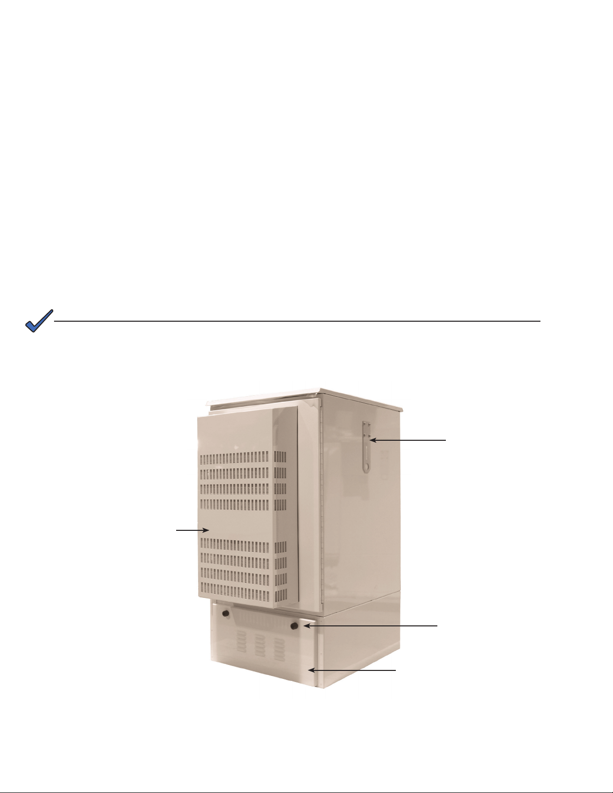
Air Conditioning Unit
(optional)
Lifting Ear
Pin Allen Telecom
Security Locks
Battery Storage Unit
(lockable)
Fig. 1-1, MiniBay Cabinet
10
044-001-C0-003, Rev. C
Page 11
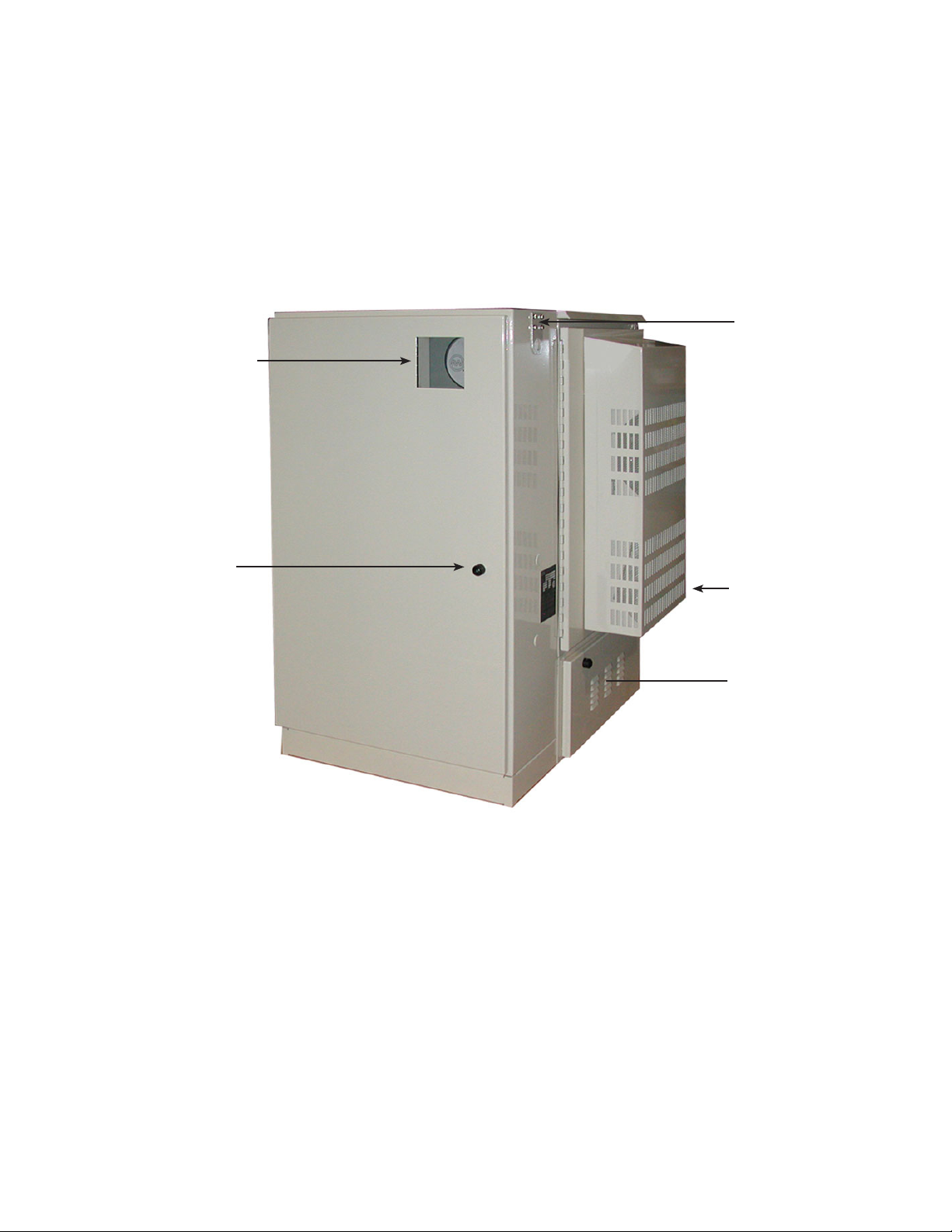
1.0 OverviewandSpecications,continued
Viewing Window
Lifting Ear
Lockable Door
Air Conditioning
Unit
Battery Storage Unit
(lockable)
Fig. 1-2, Typical MiniBay Cabinet Conguration, with Side Chamber
11044-001-C0-003, Rev. C
Page 12
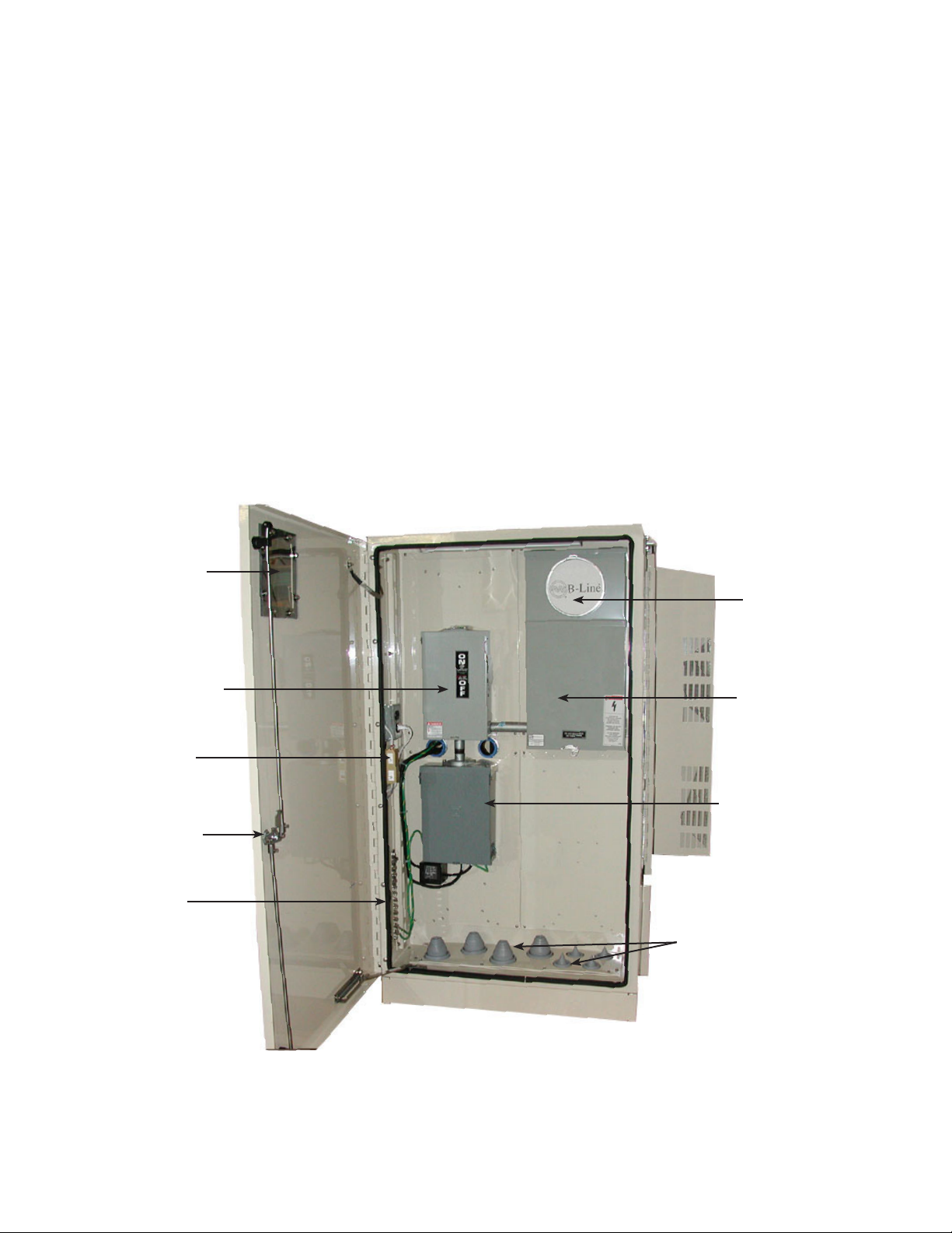
1.0 OverviewandSpecications,continued
MiniBayconguredwiththefollowingoptions:
Side Chamber (designed to NEMA 4X specications)
60A Internal AC Service (Square D QO Series)
EUSERC Meter Base (240VAC with Test Bypass Blocks)
Fusible Service Entrance Disconnect (100,000 AIC rating)
Side Chamber Door Viewing Window
TVSS (Transient Voltage Surge Suppression) Module
Cable Entry Seals
Master Ground Bar
Telcom 3-point Door Latch
Door Activated Light and Tamper Switch
Also shown on this unit:
3,000 BTU DC Air Conditioner
Battery Storage Unit
Pin Allen Telecom Locks
Viewing Window
Fused Disconnect
Door-activated
Tamper Switch
and Light.
Pin Allen 3-point
Door Latch
Ground Bar
Meter Base
EUSERC
Meter Base
AC Distribution
Breaker Panel
Cable Entry Port Seals
12
Fig. 1-3, Interior View of the MiniBay Side Chamber
044-001-C0-003, Rev. C
Page 13
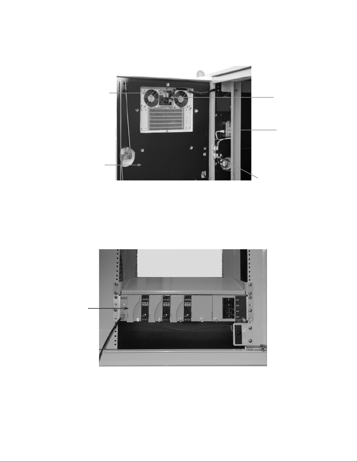
1.0 OverviewandSpecications,continued
DC Air Conditioning Unit
Insulating Material
(used on front/rear
doors and interior of
cabinets equipped with
air conditioning)
Fig. 1-4, Equipment Bay Detail
Air Conditioner
Controller Board
GFCI
Convenience
Outlet
Door-activated Switches
(tamper alarm and service light)
Rectier Shelf
(Cordex 48-650W
shown)
Fig. 1-5, Electronic Components (typical)
13044-001-C0-003, Rev. C
Page 14
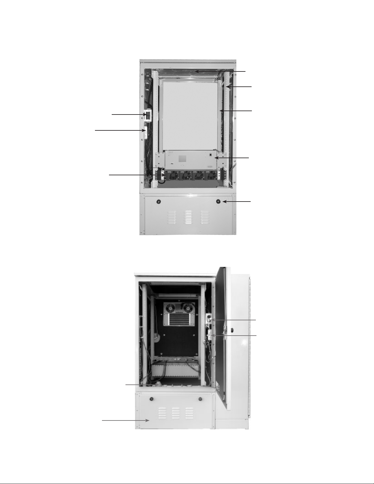
1.0 OverviewandSpecications,continued
Front Service Light
Equipment Rack
(23" shown)
GFCI Convenience Outlet
Door-activated
Switches
(tamper alarm and
service light)
48-1.8kW Rectier Shelf
(shown)
19" Rear Swing Rack
Front Access Circuit Breaker
Distribution Center with
Integrated Cordex Controller
(shown)
Lockable Battery
Module
Fig. 1-6, Equipment Bay, Front View
14
GFCI Convenience Outlet
Door-activated Switches
(tamper alarm and
service light)
Cable Entry Port Seals
Lockable Battery
Compartment
Fig. 1-7, Equipment Bay, Rear View
044-001-C0-003, Rev. C
Page 15
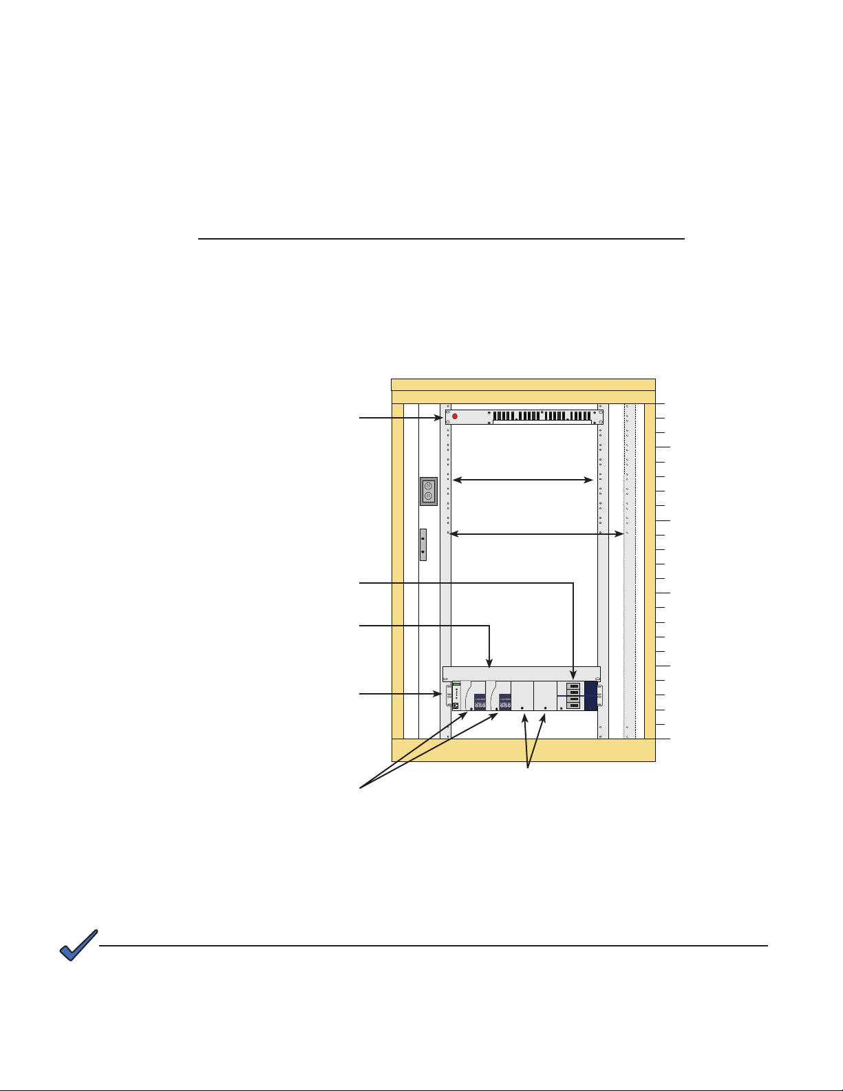
1.0 OverviewandSpecications,continued
1.1 StandardCordexCongurations
The Radium MiniBay may be equipped with Cordex 48-650W, 48-1kW, or 48-1.8kW AC/DC
rectiers. Previous models were equipped with RSM 48/10 AC/DC rectiers. Due to customer
requirements, the following illustrations may not resemble your model exactly.
RMB DC Power & Distribution Standard Conguration #1
• Cordex 48-650W 19" shelf with two rectier modules with load LVD
• Provides 13.5A @ 48VDC, N+1
• Fully equipped shelf provides 2.6kW (54A @ 48VDC), N+0
• 2RU shelf needs 1RU above and below, convection cooled
• Heat dissipation <221 BTU/hr, per rectier module
• Comnet GMT fuse panel, 10A/10B position -48VDC
GMT Fuse Panel
2 RU
P/N C016-111-10
10A/10B -48VDC
(Rack Units)
23
20
Load Breakers (qty 4)
Available Sized 1-100A
19" or 23" Heat Deector
1 RU
CDX 19/23" 48-650W Shelf
2 RU
P/N 030-728-20-A010
208/240AC CXCI, Load LVD
(Battery LVD available)
CXRC 48-650W Rectier Modules (qty 2-4)
2 RU
P/N 010-570-20-A002
19" Rack
23" Rack
HEAT DEFLECTOR
Blank Plate
P/N 030-728-20-A005
15
10
5
0
Fig. 1-8, Radium MiniBay Standard Conguration #1
NOTE:
For units equipped with a Battery LVD, a manual reset of the battery contactor is required after the low voltage
disconnect has been tripped, if there is no resumption of AC power, and DC power is applied to the unit using
an alternate power source (DC generator).
15044-001-C0-003, Rev. C
Page 16
1.0 OverviewandSpecications,continued
1.1 StandardCordexCongurations,continued
RMB DC Power & Distribution Standard Conguration #2
• Cordex 1.8kW 19" Shelf, with two Cordex 48-1.8kW rectier modules
• Provides 37.5A @ 48VDC, N+1
• Fully equipped shelf provides 7.2kW (150A @ 48VDC), N+0
• 2 RU shelf, fan cooled
• Heat dissipation <350 BTU/hr, per rectier module
• 584 Distribution Center with Cordex Controller, load LVD, eight load breakers, and shunt
Front ACS Distribution Center
5 RU
P/N 020-584-20-A012
19/23" 48VDC 400A
8 position Circuit Breaker
Sized 1-100A with Load LVD
2 to 4 (qty) CXCM 48-1.8kW Rectier Modules
2 RU
P/N 010-580-20-A001
ARGUS
TECHNOLOGIES
P/N 020-584-20
23
19" Rack
23" Rack
Leave 1RU Space
SM03
Blank Plate
P/N 030-749-20-A002
(Rack Units)
20
15
10
5
CDX 19" Shelf
2 RU
0
48-1.8kW
P/N 030-749-20-A001
208/240VAC
16
Fig. 1-9, Radium MiniBay Standard Conguration #2
044-001-C0-003, Rev. C
Page 17
1.0 OverviewandSpecications,continued
1.1 StandardCordexCongurations,continued
NOTE:
Rack height is shown in Rack Units (RU). One RU is equal to 1.75 inches.
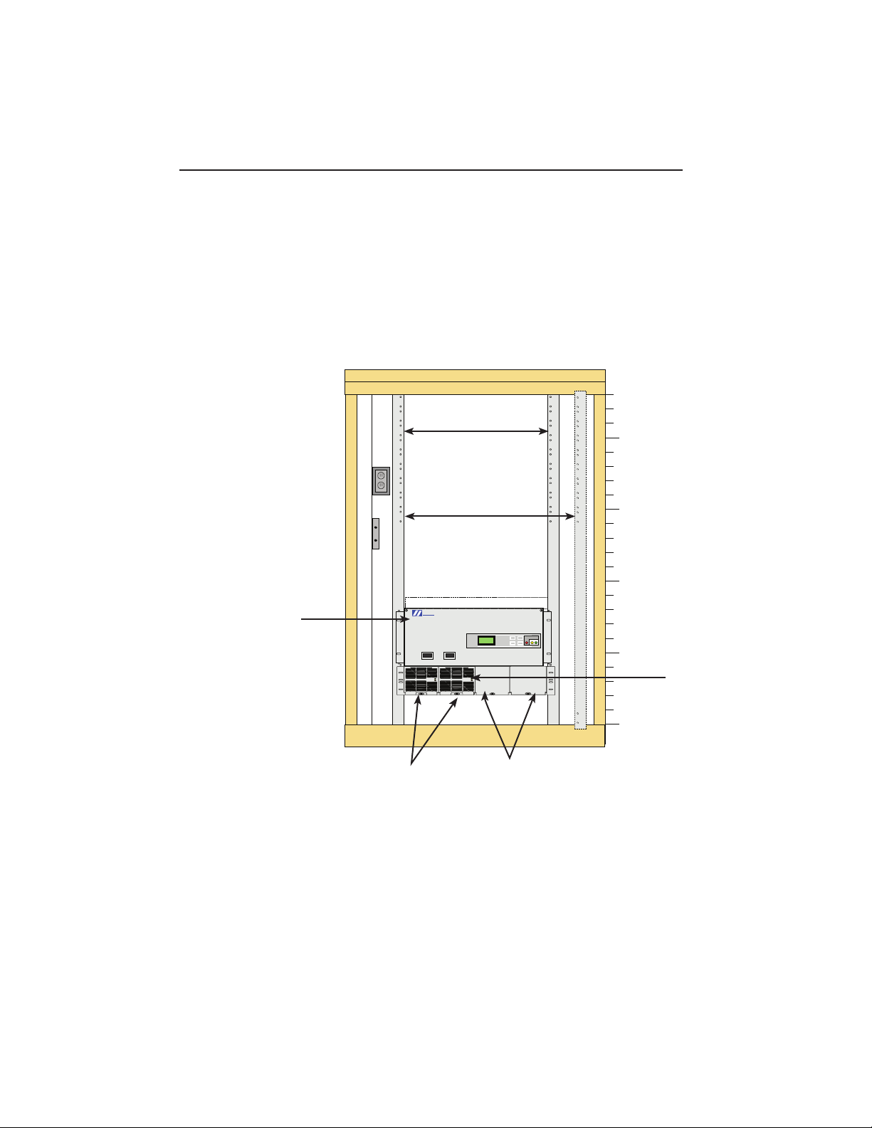
Equipment Rack Side ViewEquipment Rack Front View
15.0"
20
P/N 020-584-20
ARGUS
TE
CHNOLOGIES
Leave 1RU Space
SM03
15
10
Front Door
5
19" Rear Equipment
Rack (xed)
0
Installed in fourth
hole position
23.5"
32.0
"
Fig. 1-10, Radium MiniBay Equipment Rack View
17 RU Available
for Equipment
19" Rear Equipment
Rack (swing)
NOTE:
For wiring diagrams and alarm information, see Radium MiniBay System Schematics, Alpha P/N 044-001-05.
Contact Alpha Application Engineering for information on Cordex congurations.
17044-001-C0-003, Rev. C
Page 18
1.0 OverviewandSpecications,continued
1.2 EnclosureSpecications
Equipment Enclosure Weight: 195 lbs (88.5kg)
19" or 23" wide Fixed Relay Rack
tapped or with Tinnerman nuts
19" Swing Rack (tapped only)
Battery Storage Unit Weight (without batteries): 130 lbs (59kg)
Slide Tray, Alpha P/N 033-083-20,
will hold four GNB M12V155FT batteries
Fixed Tray, Alpha P/N 033-083-23,
will hold three Avestor batteries.
Riser Module
14" Riser Alpha P/N 033-083-21
7" Skirt/Riser Alpha P/N 033-084-20
7" C-channel Riser Alpha P/N 745-650-20
Side Chamber SC1 Weight: 100 lbs (45.4kg)
Side Chamber SC2 Weight: 89 lbs (40.4kg)
Dimensions (in/mm):
44H x 30W x 32D (1067 x 762 x 813)
Material: High Strength Corrosion Resistant
Aluminum
Finish: Almond Color Powdercoat Finish
Dimensions (in/mm):
14.0H x 30W x 32D (356 x 762 x 813)
Weight: 102 lbs (46.3kg)
Dimensions (in/mm):
14H x 30W x 32D (356 x 762 x 813)
Dimensions (in/mm):
72H x 32W x12D (813 x 1829 x 305)
Dimensions (in/mm):
58H x 32W x 12D (813 x 1321 x 305)
1.3 MiniBay Accessories
Precast Polymer Concrete Padfor Single Radium MiniBay P/N 641-110-10
Precast Polymer Concrete Pad for Single Radium MiniBay + Side
Chamber
Pour-in-place Pad Template P/N 604-039-N1
Pour-in-place Pad Template Tie-bars (spacers for 2 template kits) P/N 745-332-20
Pour-in-place Side Chamber Template P/N 745-333-20
Vapor Barrier for MiniBay (die cut template matches MiniBay) P/N 564-990-10
SRG PROT, 5-pin, Gas Tube, 3B1E P/N 162-016-10
Touch-up Spray Paint, Almond P/N 972-056-10
Pad Mounting Hardware Kit (4 Hilti KBII sleeve anchors 1/2 x 3-3/4) P/N 745-592-21
Pad Mounting Hardware (4 Hilti HSLG M12/0 *60 heavy duty sleeve
anchors) requires 12mm metric drill Kit for Zone 4
P/N 641-114-10
P/N 745-592-20
18
044-001-C0-003, Rev. C
Page 19

1.0 OverviewandSpecications,continued
1.4 Enclosure Cooling Options
NOTE:
Consultation with Alpha Applications Engineering is required. Provisions must be made for adequate air
ow in the cabinet, equipment total heat dissipation load inside the cabinet, equipment min/max operating
temperatures, equipment over-temp fail safe shutdown capability, environmental outdoor design conditions,
and battery back up run times.
FanFilterCoolingDoor,48VDC,rightorlefthinged:AlphaP/N745-204-20(R)or745-204-21(L)
• Cooling capacity 1000W dissipated with 15ºC rise over ambient.
• Two 150 CFM fans with variable speed temperature control and low voltage disconnect, hysteresis xed
at 42VDC.
• Inline 5A fuse.
• Fans run continuously below 25ºC at 40% speed. Fans increase from 40% to 100% with increased
enclosure temperature from 25ºC to 55ºC.
• Form C dry contact alarm, fan fail, open on alarm.
• Maximum power draw 32W.
FanFilterCoolingDoor,120VAC,rightorlefthinged:Alpha745-204-25(R)or745-204-24(L)
• Cooling capacity 750W dissipated with 15ºC rise over ambient.
• Two 115 CFM fans are powered from the included line cord with designated inline 5A fuse and bimetal
thermostat control (Alpha P/N 875-075-20).
• Fixed thermostat set point, close at 29ºC and open at 19ºC.
• Included adjustable enclosure over-temp alarm (Alpha P/N 745-338-20).
• Form C dry contact, open on alarm. Factory setting is 40ºC.
• Maximum power draw 30W.
HeatExchangerDoor,48VDC,rightorlefthinged:AlphaP/N745-204-45(R)or745-204-46(L)
• Cooling capacity 690W dissipated with 15ºC rise over ambient.
• Variable speed fan temperature control and low voltage disconnect. Fans off below 23ºC. Fans turn on at
25ºC and run from 25% to 100% with increased enclosure temperature from 25ºC to 45ºC.
• Two Form C dry contact alarms (Minor: Fan fail, open on alarm and Major: Enclosure over-temp xed at
60ºC, open on alarm).
• Maximum power draw 120W.
HeatExchangerCoolingDoor,120VAC, rightorlefthinged:AlphaP/N745-204-40(R)or745-204-41(L)
• Cooling capacity 690W dissipated with 15ºC rise over ambient
• Heat exchanger fans are powered from included line cord with designated inline 5A fuse and bimetal
thermostat control (Alpha P/N 875-075-20)
• Fixed thermostat set point, close at 29ºC and open at 19ºC
• Included adjustable enclosure over-temp alarm (Alpha P/N 745-338-20). Form C dry contact, open on
alarm. Factory setting is 40ºC.
• Maximum power draw 115W.
19044-001-C0-003, Rev. C
Page 20

1.0 OverviewandSpecications,continued
1.4 EnclosureCoolingOptions,continued
AirConditionerDoor,48VDC,rightorlefthinged:AlphaP/N745-204-50(R)or745-204-51(L)
• Cooling capacity 878W dissipated at 43ºC outdoor ambient and maximum internal ambient temperature
of 40ºC.
• Variable speed compressor temperature control and low voltage disconnect.
• Adjustable enclosure temperature set point jumper, factory set to 25ºC.
• Two Form C dry contact alarms (Minor: High condensing temp and/or enclosure over-temp, open on
alarm and Major: cooling system failed, open on alarm). See DC air conditioner operation section for
details.
• Maximum power draw 500W.
AirConditionerDoor,24VDC,rightorlefthinged:AlphaP/N745-204-52(R)or745-204-53(L)
• Cooling Capacity 878W dissipated at 43ºC outdoor ambient and maximum internal ambient temperature
of 40ºC.
• Variable speed compressor temperature control and low voltage disconnect. Adjustable enclosure
temperature set point jumper factory set to 25ºC.
• Two Form C dry contact alarms (Minor: High condensing temp and/or enclosure over-temp, open on
alarm and Major: cooling system failed, open on alarm). See DC air conditioner operation section for
more details.
• Maximum power draw 500W.
AirConditionerDoor,240VAC,rightorlefthinged:AlphaP/N745-204-58(R)or745-204-59(L)
• Cooling capacity 1464W dissipated at 43ºC outdoor ambient and maximum internal ambient of 40ºC.
• Digital display with programmable set points.
• Included adjustable enclosure over-temp alarm (Alpha P/N 745-338-20).
• Form C dry contact, open on alarm. Factory setting is 40ºC. See AC air conditioner operation section for
more details.
• Maximum power draw 989W.
1.5 Enclosure Heating Options
Heater,450W,48VDC:AlphaP/N745-588-22or745-588-21
• PCBA thermistor temperature control and low voltage disconnect.
• Heater turns on when enclosure temperature drops below 6ºC.
• Functional test button.
• Model 745-588-22 includes 20A circuit breaker.
• Model 745-588-21 does not include circuit breaker, but has a piggyback connector that allows it to share
input power from the DC air conditioner 20A circuit breaker.
Heater,450W,120VAC:AlphaP/N745-589-21
Line cord with bimetal thermostat control. Thermostat set point is xed to close at 4ºC and open at 15ºC.
Plugs into GFCI outlet.
20
044-001-C0-003, Rev. C
Page 21

1.0 OverviewandSpecications,continued
1.6 Storage Unit Cooling Options
Fan,120VAC:AlphaP/N745-214-21
One 64CFM fan powered from 875-075-20 line cord with designated in-line 5A fuse and bimetal thermostat
control. Thermostat set point is xed to close at 29ºC and open at 19ºC.
Fan,48VDC:AlphaP/N745-214-20
• One 110CFM fan, turns off below 25ºC. Turns on at 25ºC and increases from 40% to 100% full speed with
increased enclosure temperature from 25ºC to 45ºC.
• Form C dry contact alarm, fan fail, open on alarm.
Fan,24VDC, AlphaP/N745-214-22
• One 110CFM fan, turns off below 25ºC. Turns on at 25ºC and increases from 40% to 100% full speed with
increased enclosure temp from 25ºC to 45ºC.
• Form C dry contact alarm, fan fail, open on alarm.
21044-001-C0-003, Rev. C
Page 22

1.0 OverviewandSpecications,continued
1.7 BatteryStorageUnitBatteryOptions
The Battery Storage Unit (slide tray), Alpha P/N 033-083-20, and Battery Storage Unit (xed
tray), Alpha P/N 033-031-21, accommodates four of the following battery types:
• C&D TEL 12-45
• C&D TEL 12-70
• AlphaCell 85GXL-HP
• AlphaCell 165GXL
• AlphaCell 185GXL
• AlphaCell 195GXL-3FTG
• AlphaCell 225AGM-3FTA
• C&D TEL 12-105F
• GNB Marathon M12V155FT
• AlphaCell SMU12V 155F
The Battery Storage Unit (xed tray) also accommodates three Avestor SE48S63 48VDC
batteries.
22
Fig. 1-11, Battery Storage Unit
The MiniBay equipment enclosure can house a maximum of four batteries on the oor of
enclosure when the fan ltered cooling door or roof vent option is used. The roof vent must
have a minimum of four .375" vent holes to provide adequate hydrogen venting (Alpha P/N
745-669-20 or equivalent). The following batteries may be used in the battery compartment or
equipment enclosure:
• C&D TEL 12-45
• C&D TEL 12-70
• AlphaCell 85GXL-HP
• AlphaCell 195GXL-3FTG
• AlphaCell 225AGM-3FTA
044-001-C0-003, Rev. C
Page 23

2.0 DC Air Conditioner
2.1 Overview and Theory of Operation
The MiniBay DC Air Conditioner comes in 24V and 48V models and uses a brushless
compressor and variable speed controller. A temperature control board varies capacity by
varying compressor speed depending on the enclosure internal setpoint temperature. The
compressor runs between 50% and 100% of full speed depending on the load and enclosure
set point temperature. When the temperature drops more than 4°C below the set point, the
compressor and condenser fans shut off. The evaporator fans run continuously regardless of
the set point to maintain an even temperature inside the enclosure.
Theory of Operation:
1. Low pressure gas is drawn into the compressor.
2. The high pressure gas is sent through a condenser where air is blown over it, cooling the
gas into a liquid.
3. The high pressure liquid passes through an expansion valve, where the liquid is allowed
to expand and boil off into a gas. As the gas expands, it cools.
4. The cool saturated low pressure gas is sent through the evaporator. Warm interior air is
blown over the evaporator and back into the interior, several degrees cooler.
5. The low pressure gas is then drawn into the compressor, where the cycle starts over.
Thermostatic
Expansion Valve
-48VDC Bus
Ground
Return Bar
Minor Alarm Connect
Major Alarm Connect
Evaporator
Liquid is allowed to expand at
low pressure back into gas,
cooling interior air.
20A
Temp
Control
Board
Speed Control
Board
Evaporator Fans
(always on)
Suction Line
Liquid Line
Sight Glass
Discharge Line
Variable Speed
Compressor
Condenser Fans
(thermostatically controlled)
Condenser
Hot gas is cooled by outside
ambient air and condensed
into a high pressure liquid.
Fig. 2-1, DC Air Conditioner Basic Block Diagram
23044-001-C0-003, Rev. C
Page 24

2.0 DCAirConditioner,continued
2.2 DCAirConditionerSpecications
Capacity: 3,000 BTU @ 110°F (43ºC) See chart below
External Amb. Operating Range: -40°C (-104°F) to +50°C (+122°F) RH 13%
Max Internal Amb. Temperature: +40°C (+104°F) RH 25%
Maximum Internal Hysteresis: 10°C (50°F)
Maximum Operational Power Draw: 500W ±10% (see chart)
DC Operation @ 48VDC: 42VDC to 60VDC range with LVD xed at 42V
DC Operation @ 24VDC: 21VDC to 30VDC range with LVD xed at 21V
Cooling System Control: Low current DC or dry contact on/off
Major Alarm: Compressor/controller system fail
Minor alarm: High condensing temperature, Low evaporator
Refrigerant Type: R134a
Fan Life: >50,000 Hours
Color: Almond semigloss (other colors available)
External Dimensions (in/mm): 19.50 W x 38.25 H x 7.50 D (495 x 972 x 191)
Agency: CSA
Enclosure Rating: IP55 - Weather tight hose directed spray
Noise Level: 60 dBA at one meter
Materials: Corrosion and salt-fog resistant (including fans)
circuit breaker, magnetic short delay 15A
circuit breaker, magnetic short delay 30A
temperature, Enclosure over-temp
1400
1200
1000
800
600
Capacity Wattage
400
200
0
10 20 30 40 50
Ambient Temp (C)
Capacity (watt/hr)
Total Unit Watts
NOTE:
The chart above table illustrates air conditioner capacity under controlled conditions. A safety factor should
be used depending on cabinet insulation and outside air ltration. To calculate capacity in BTUs at a given
outdoor ambient temperature multiply 3.413 x (capacity watt/hr).
24
044-001-C0-003, Rev. C
Page 25

2.0 DCAirConditioner,continued
2.3 Temperature Control Board
The temperature control board monitors the compressor, condenser fan, and alarm control.
Its remote temperature sensors monitor compressor discharge and evaporator suction line
temperature. A board-mounted temperature sensor monitors enclosure temperature. An
optional remote temperature sensor can monitor a specic area in the enclosure. The board
incorporates a low-voltage shutdown xed at 42V for the 48VDC air conditioner, and 21V for
the 24VDC air conditioner.
A temperature sensor on the discharge line of the compressor regulates the condenser fans.
At low outdoor ambient temperatures, the condenser fans cycle on or off to maintain pressure
across the expansion valve.
A temperature sensor on the suction line exiting the evaporator monitors low evaporator
temperature, which can result from blocked evaporator air ow or faulty evaporator fans. This
condition sends out a minor alarm and shuts down the compressor until the suction lines
warm up again.
704-713-
Temperature
Set Point Jumper
Local-Remote Temp
Sensor Jumper
DC Power
Input
+
-
DC Aux
Output
+ -
Major/Minor
Alarm Output
Under Temp
Shutdown Jumper
Enclosure Over
Temp Jumper
Minor Alarm LED and
N/C - N/O Jumper
Major Alarm LED and
N/C - N/O Jumper
Remote Enclosure
Temp Probe
Fig. 2-2, Temperature Control Board
25044-001-C0-003, Rev. C
Page 26

2.0 DCAirConditioner,continued
2.3 TemperatureControlBoard,continued
AIR COND TEMP CONTROL
SHDOWN
Evap temp
MINOR
J10
ALARM
SETPOINT
18C
23C
MAJO
N0NC
R
MAJOR4MAJOR3MINOR2MINOR
1
28C
33C
38C
N0NC
PWR (+)1PWR (-)
MM
L
(-)
J11
J12
(+)
2
Evap Temp Sensor
LOCAL
RMT
Remote T
em
p
J1
SPEED CONTROL BOARD
PWR (-)
PWR (+)
Cond Temp Sensor
(BREAKER IS INSTALLED ON THE UNGROUNDED LEAD)
BLACK
RED
RED
YELLOW
48 or 24VDC
MAJOR ALARM CONNECT
MINOR ALARM CONNECT
EVAP FANS
COMPRESSOR
A
B
C
COND FANS
26
Fig. 2-3, Wiring Diagram
044-001-C0-003, Rev. C
Page 27

2.0 DCAirConditioner,continued
2.4 Air Conditioner Installation and Removal
Allow 20 minutes for completion of procedure.
Tools required: 7/16" deep-well socket and ratchet handle
Removal:
1. Disconnect power to the air conditioner.
2. Disconnect input and alarm wires from the control board (see Fig. 2-2).
3. From the inside of the door, remove the 5 bolts (labeled S below) holding the shroud to
the door. Remove the shroud. Remove grounding lug.
4. While another installer supports the air conditioner on the outside of the door, remove the
10 remaining bolts (labeled A below). Remove the air conditioner.
5. Reverse order for installation. Replace PORON washers if they are damaged (Alpha P/N
684-020-10).
S
S S
–
S
A
A
A
A
–
S
A
A
A
A
A
A
Fig. 2-4, Shroud and Air Conditioner Bolts
27044-001-C0-003, Rev. C
Page 28

2.0 DCAirConditioner,continued
2.5 48/24VDCPowerConnection
Allow 20 minutes for completion of procedure.
Tools required: Assorted wrenches and screwdrivers
1. Install circuit breaker mounting plate in a convenient location near the 48/24VDC source
(see Fig. 2-5 below). Leave circuit breaker IN THE OFF POSITION.
2. Connect black wire leading from circuit breaker to the 48/24VDC Bus.
3. Connect the red wire to the ground/return bar.
The air conditioner can be positively or negatively grounded. The overcurrent protection
must be placed in the ‘Hot’ lead.
Circuit
Breaker
To Ground Return Bar
Fig. 2-5, Power Connections
To Circuit Breaker
28
044-001-C0-003, Rev. C
Page 29

2.0 DCAirConditioner,continued
2.6 Alarm Connector
1. Set major and minor alarm jumpers to the desired position.
2. Connect yellow wire (minor) and red wire (major) to status monitoring device.
Minor Alarm Jumper
Shown Normaly Closed
2.7 FunctionTest
1. Set the 48VDC Circuit Breaker to the ON position.
2. Remove SETPOINT jumper and verify fans are running. Compressor will start after 10
second delay.
3. Replace SETPOINT jumper and verify AC unit shuts down.
Major Alarm Jumper
Shown Normaly Closed
Fig. 2-6, Alarm Connections
SETPOINT Jumper
Fig. 2-7, Setpoint Jumper
29044-001-C0-003, Rev. C
Page 30

2.0 DCAirConditioner,continued
2.8 Jumpers
Enclosure Temperature Setpoint Jumper
Determines what temperature the system will maintain inside the enclosure. The diagram
below details the start and shutdown temperatures for each setting.
104°F/40°C
95°F/35°C
86°F/30°C
77°F/25°C
68°F/20°C
59°F/15°C
50°F/10°C
40° C Maximum Internal Temp.
38° C Startup
38° C Setpoint
34° C Shutdown
33° C Startup
33° C Setpoint
29° C Shutdown
28° C Startup
28° C Setpoint
24° C Shutdown
23° C Startup
23° C Setpoint
19° C Shutdown
18° C Startup
18° C Setpoint
14° C Shutdown
Remote Temperature Sensor Jumper
Determines where the control card gets its temperature information. In the LOCAL position
the card receives temperature information from its onboard temperature sensor. In the RMT
position, temperature information is received from an optional Remote Temperature Sensor
that can be placed anywhere in the enclosure.
Major and Minor Alarm Jumpers
Determines the state of the alarm relays in the non-alarm state. In the NO position, the nonalarm state is OPEN. In the NC position, the non-alarm state is CLOSED.
NOTE:
See Fig. 2-2 for jumper locations.
30
044-001-C0-003, Rev. C
Page 31

2.0 DCAirConditioner,continued
2.9 DC Air Conditioner Preventative Maintenance
A preventative maintenance check should be conducted on initial startup, and on a yearly
basis thereafter.
1. Check that the evaporator fans, located on the inside of the door, run continuously.
2. Remove temp setpoint jumper. Make sure the compressor comes on after 10 seconds.
3. Check for proper function of the outdoor condenser fans (located under the shroud on the
outside of the door). The outdoor condenser fans are controlled by the temperature of the
outdoor condenser coil. These fans should cycle on and off, or run continuously when the
setpoint jumper is removed. They may not turn on unless outdoor ambient is above 70ºF
(21ºC). As the outdoor condenser coil heats up, rst one fan and then the other cycles
on. If the unit is hot already, the fans turn on simultaneously, when the setpoint jumper is
removed. After ten seconds the compressor will turn on.
4. Using a DC clamp-on ampere probe, check the input current to the air conditioner while
the compressor is running. The 48VDC air conditioner should draw between 6A and
10.4A (10.4 FLA, Full Load Amps), for normal operation. The 24VDC air conditioner
should draw between 12A and 20.8A (20.8 FLA).
5. Replace setpoint jumper when functional check is complete.
6. Visually inspect the outdoor condenser coil with a ashlight. It should look clean and clear
of debris. If there is excess dirt build up, turn off circuit breaker, remove shroud and clean
it with soft brush or compressed air (be careful not to damage ns).
7. With a ashlight, visually inspect that the condensate drain is working and clear of debris.
There should be no excess water build up in the pan below the inside evaporator coil.
The evaporator coil should be offset far enough so water drips into the drain pan below,
and does not bead up on the edge of the door.
8. To complete the check, replace the setpoint jumper and all guards. Turn the circuit
breaker on.
31044-001-C0-003, Rev. C
Page 32

2.0 DCAirConditioner,continued
2.10 DC Air Conditioner Trouble Shooting
ATTENTION:
Contact Alpha Technical Service to determine proper diagnosis. See page 3 for contact information.
1. Check that wire connections and input voltage are correct.
2. Check the evaporator and condenser thermostat wires are not reversed. These are on
the inside of the evaporator box and look like telephone jacks. The evaporator sensor is
attached to the suction line inside the evaporator box. The condenser sensor goes to the
outside and attaches to the discharge line. Look on the front of the PCBA for silkscreen
connector label “EVAP” and “COND”. If these are reversed the condenser fans will not
turn on, and the circuit breaker will trip.
3. When the breaker is turned on, both evaporator fans should run continuously.
4. Verify the compressor comes on 10 seconds after pulling the setpoint jumper.
5. Watch the sight glass for bubbles. Bubbles should go to clear liquid after about a minute.
If there are no bubbles or liquid ow, or the moisture indicator shows wet and the bubbles
don't clear, there is low or no charge. This is not eld serviceable, and the unit should be
replaced.
6. Check the discharge line to see if it is warming up. Both condenser fans should come on
(rst one, then the other) when discharge line is above 104ºF (40ºC).
7. If unit control board indicates a yellow LED minor alarm, check for plugged outdoor
condenser or bad condenser fan.
8. If the unit control board indicates a red LED major alarm, the compressor may be over
heated or overloaded, or there is a bad three-phase connection to the compressor. Check
for a plugged outdoor condenser, or compressor overload.
9. Using a DC clamp-on ampere probe, check the input current to the air conditioner while
the compressor is running. The 48VDC air conditioner should draw between 6A and
10.4A (10.4 FLA, Full Load Amps), for normal operation. The 24VDC air conditioner
should draw between 12A and 20.8A (20.8 FLA).
10. Check the Delta-T across the evaporator coil. It should be between 9ºF and 18ºF (5ºC
and 10ºC).
11. The unit is overloaded if the FLA is too high and evaporator Delta-T is 9ºF (5ºC).
• Check heat dissipation load inside the cabinet.
• Check blocked condenser or bad condenser fans.
12 Check the suction line entering the compressor. It should be getting cooler. If it is not
getting colder, and the sight glass looks full or clear, there may be a refrigerant blockage
at the TX valve screen (this is not eld serviceable). Replace the unit and send it back
for evaluation and repair. To protect the unit from damage during shipping, use proper
packing to keep the unit in an upright vertical position.
32
044-001-C0-003, Rev. C
Page 33

2.0 DCAirConditioner,continued
2.11 DC Air Conditioner Parts List
Part Number Description
745-289-20 48VDC, 3000BTU replacement air conditioner assembly for Radium MiniBay
745-355-20 48VDC,150CFM outdoor condenser fan with sealed connectors
(qty 2 per unit)
500-074-10 48VDC,126CFM Inside Evaporator fan (qty 2 per unit)
704-713-20 48VDC, temperature control PCBA.
745-356-20 48VDC, controller inside fan assembly (contains 2 evaporator fans,
temperature control board, variable speed controller)
745-289-40 24VDC, 3000BTU replacement air conditioner assembly for Radium MiniBay
745-355-40 24VDC,150CFM outdoor condenser fan with sealed connectors
(qty 2 per unit)
500-087-10 24VDC,126CFM inside evaporator fan (qty 2 per unit)
704-713-21 24VDC, temperature control PCBA.
745-356-40 24VDC, controller inside fan assembly (contains 2 evaporator fans,
temperature control board, variable speed controller)
33044-001-C0-003, Rev. C
Page 34

3.0 AC Air Conditioner
IceQube AC Air Conditioner Overview, Basic Theory of Refrigeration:
1. The compressor pump draws in and compresses cool, low-pressure gas into a high pressure gas.
Compression raises the boiling point of the gas.
2. The hotter, high-pressure gas passes through a coil called a condenser. A fan blows air over the
coil which cools the gas into a liquid.
3. This high-pressure liquid passes through an expansion valve, where the liquid expands to boil off
as a gas. As the gas expands, it absorbs heat.
4. The cool low-pressure gas is sent through another set of coils called an evaporator or heat
exchanger. Warm interior air is blown over the coil and back into the interior, several degrees
cooler.
5. The low-pressure gas is then drawn into the compressor, where the cycle starts over. The
air conditioning system is actually three systems, which function simultaneously to maintain
environmentally friendly conditions for your equipment within the enclosure: The closed-loop cold
air system, warm air system, and vapor-compression refrigeration system.
The closed-loop cold air system circulates cold air from the cooling system to the electronics
enclosure. This air captures the heat and humidity within the enclosure and carries it through the heat
exchanger, the part of the vapor-compression system that removes the heat/humidity.
The vapor-compression refrigeration system is run by an efcient rotary compressor which circulates
NON-CFC refrigerant to transfer heat from the heat exchanger (evaporator) in the closed-loop air
stream to a condenser located in the warm air system. Heat from the enclosure transfers from the
warm air heat exchanger and dissipates to the ambient.
34
Air Filter Access
Fig. 3-1, AC Air Conditioner
044-001-C0-003, Rev. C
Page 35

3.0 ACAirConditioner,continued
3.1 VerifyingDefaultSettingsfortheIceQubeAirConditioner
Procedure:
1. Remove IceQube controller's access panel on the enclosure door shroud (2 screws).
2. Turn on the AC power.
3. Record the displayed temperature information.
4. Check the STATUS LEDs (On/Off/Blink):
• COOL - On if temperature is above 70ºF
• HEAT - On if temperature is below 32ºF
• ALM - Contact Alpha
• FILT - Turn off lter alarm (if on) and clean lter if needed
5. To enter programming mode, enter the default PIN code in sequence on the front panel
display. The code must be entered with less than 2 seconds between keystrokes.
• ADJUST up arrow (1)
• ADJUST down arrow (2)
• SELECT (3)
• EXIT (4)
6. The programming LEDs ashes, and a pattern of boxes appears in the digital display to
indicate program mode has been entered. If no selection is made within one minute, the
system returns to normal operating mode.
7. To verify or adjust the AC default parameters use the ADJUST up and down arrows.
Press SELECT to accept the current setting and cycle to the next.
8. Pressing the EXIT button saves setting changes and returns the unit to normal operating
mode.
Programming LED
Cooling Mode
Heating Mode
Digital Display
General Alarm
LED's Indicate Parameter Displayed
Filter Alarm
PIN
Fig. 3-2, AC Air Front Panel Display
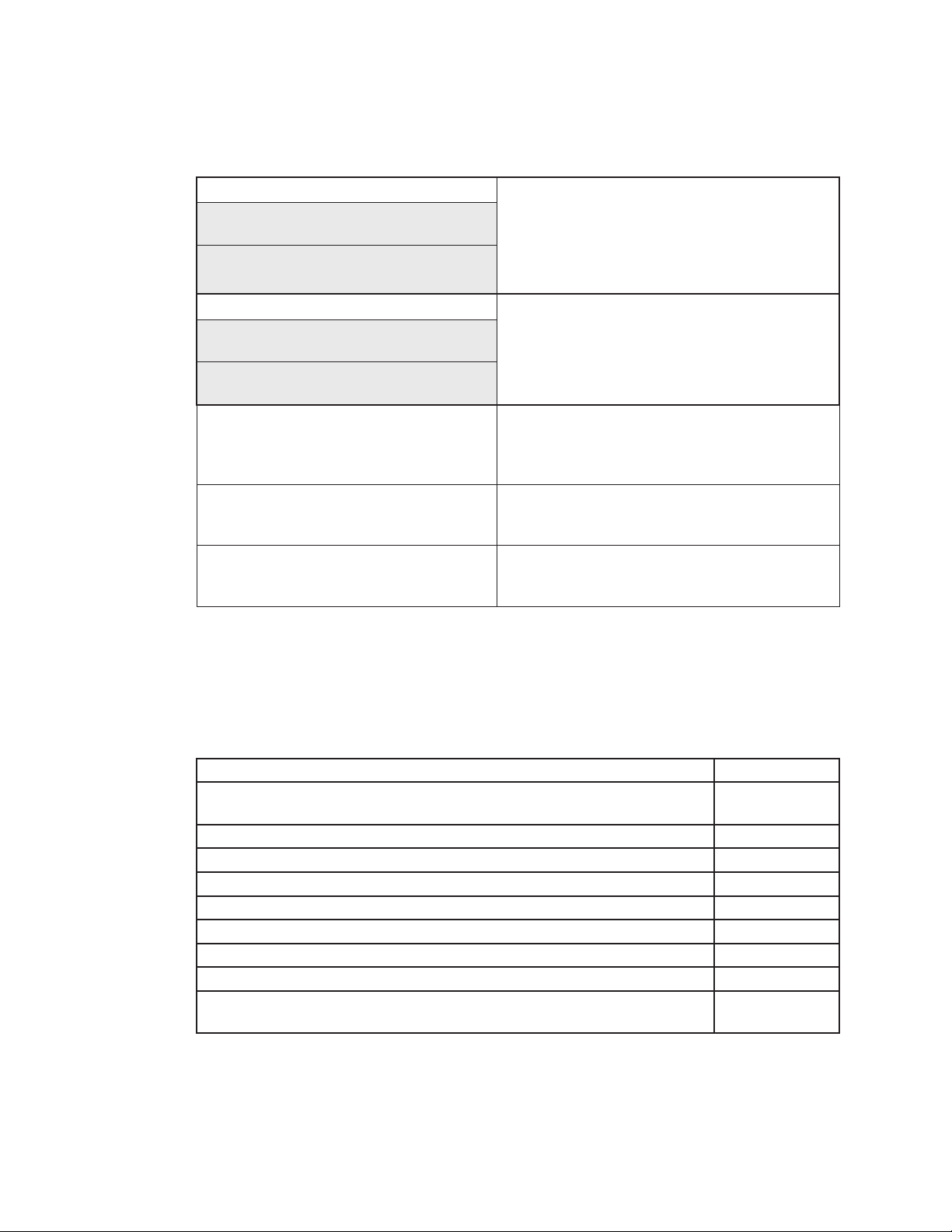
Default Settings
Parameter Default Setting
HI Temp set point: 72°F
LO Temp set point: Set to lowest limit (approx. 40°F)
HI Alarm set point: 100°F
LO Alarm set point: Set to lowest limit (approx. 33°F)
ALL: ON
AUD: OFF
-F-: Do not change
PIN: Do not change
FIL: 0.0 Days
Add: 0.0
35044-001-C0-003, Rev. C
Page 36

3.0, ACAirConditioner,continued
3.2 ACAirConditionerSpecications
Specications
Capacity 5000 BTUH (sensible) @ 43ºC ambient
Maximum Operating Temperature 125º F
Electrical 8.7A @ 120VAC/60HZ maximum
Microprocessor Controller Displays temperature in Fahrenheit and Celsius
Refrigeration System Efcient, long lasting rotary compressor
Evaporator Fan Lustran ABS 633 housing and squirrel cage
Condenser Fan Lustran ABS 633 housing and squirrel cage
4.3A @ 230VAC/60HZ maximum
4.8A @ 220VAC/50HZ maximum
UL/CUL recognized per UL50-File#SA12062 CE
Compliant
Programmable heating and cooling set points
Standard on/off differential 7º Fahrenheit
Programmable high/low temperature alarms
Condenser air lter maintenance indicator
Security programming access code
Integral EMI / RFI protection
24VAC input power
Operating status indicators for cooling, heating and
alarm conditions
Coil construction: Aluminum n with copper tube
Solid core 4 stage lter drier
Pressure balancing refrigerant ow control
HCFC refrigerant 22, Chlorodiuoromethane
Life lubricated ball bearing system
.05 HP shaded pole therm. protected motor
Maximum 247 CFM free air @120VAC/60HZ
Life lubricated ball bearing system
.05 HP shaded pole thermal protected motor
Maximum 247 CFM free air @120VAC/60HZ
36
044-001-C0-003, Rev. C
Page 37

3.0 ACAirConditioner,continued
3.3 AC Air Conditioner Condensate Hose Mounting
The MiniBay AC air conditioner comes with a condensate hose that must be secured to the
mounting pad. The hose may be run out the front or back of the pad, and should extend three
inches from the edge.
Tools Required:
• Rotary Hammer Drill with 1/4" bit
• Hammer
Procedure:
1. Locate the hose hardware kit (packaged with the battery cable kits).
2. Extend the hose out in the desired direction and position brackets.
3. Locate the anchor holes so the hose does not interfere with the door opening. Drill two
holes for the anchors into the pad.
4. Place anchors in anchor holes.
5. Run the pins through the brackets and hammer into the anchors.
6. Trim the hose to approximately three inches over the edge of the pad.
Pin
Washer
Bracket
Anchor
NOTE:
The condensate hose should have a minimum two-inch bend radius and should not kink when the door is
opened. Check the hose every six months for blockage or disconnection.
Fig. 3-3, Condensate Hose Mounting
37044-001-C0-003, Rev. C
Page 38

3.0 ACAirConditioner,continued
3.4 AC Air Conditioner Preventative Maintenance
Inspect the systems lters for replacement or cleaning every six months, depending on time
of year or environment. Clean the lters by back ushing with water in the direction indicated
and reinstall the lter. See page 3 for contact information.
NOTE:
Some environments may require more frequent inspections to maintain optimum airow.
3.5 AC Air Conditioner Troubleshooting
Contact Alpha Technologies Technical Support for troubleshooting procedures and warranty
issues. See page 3 for contact information.
3.6 Replacement or Spare 5000 AC Air Conditioner
Ice Cube 5000BTU AC Air Conditioner congured for Minibay:
KT,AIR COND,5K BTU/HR,230VAC,60HZ,RAD-MB, Alpha P/N 745-636-20
The IceQube Manual can be found on line at http://www.iceqube.com/pdf/manual.pdf
38
044-001-C0-003, Rev. C
Page 39

4.0 Site Preparation
4.1 Site Selection
Considerations:
• Where possible, select a site above the 100-year ood plain, and away from houses.
• Place in a shaded location to minimize the effects of solar loading.
• Locate in an area where airow can be maximized.
• Avoid locating the enclosure where it is an obstruction and would inhibit visibility.
• Locate the enclosure away from sprinkler systems or other sources of forced water.
• Locate the enclosure out of the prevailing wind to minimize the buildup of snow or the
accumulation of wind-borne dust.
• Evaluate the soil conditions for suitability for the installation of the required grounding
system applicable to your particular installation.
• Ensure cabling has been run and terminated at the site.
• Will the enclosure be placed on a precast concrete pad or on a pad poured on site?
• An enclosure with both front and rear doors is required for batteries with terminals located
on top. Allow for at least 36" of front and rear clearance so the door(s) may be opened
adequately for servicing.
• Contact a cable locating service, the local utility, and adjacent building supervisors
to ensure installation location and cable routing does not interfere with existing utility
connections.
NOTE:
Prior to paving the pad or placing cables and conduit, familiarize yourself with the location of the conduit
seals. The pad should include a rectangular sweep opening lled with drain rock to allow cables and conduit
to be maneuvered into position to enter the seals.
Fig. 4-1, Conduit Seal Location
39044-001-C0-003, Rev. C
Page 40

4.0 SitePreparation,continued
4.2 Precast Pads
The type of enclosure mounting pad is determined by the size of the enclosure (single bay,
single bay with side chamber, dual bay, dual bay with single side chamber, and dual bay
with dual side chambers). Typically, Alpha Technologies recommends using precast polymer
mounting pads. These pads are designed for proper cabinet support and ease of installation.
Drilling areas for openings are indicated for coax and service sweeps, and pre-installed
threaded inserts for enclosure attachment.
44" SYMM.
32" SYMM.
5-1/2"
27-3/4" SYMM.
4-5/8"
RAD-MB
.
MM.
" SYMM
SY
"
42" SYMM.
2-
1/
24" SYMM.
30
25-7/8
4"
Sweep Opening
8-1/2"
10-3/4"
Front of Pad
3-
5
/8
"
4-
1/
2"
Front of Pad
IN.
M
3"
40
Fig. 4-2, Precast Pad Dimensions for Single Enclosure
(P/N 641-110-10)
044-001-C0-003, Rev. C
Page 41

4.0 SitePreparation,continued
4.2 PrecastPads,continued
29.88"
28.62"
27.75"
26.48"
23.12"
FAR SIDE
FRONT OF
RAD-MB SC
Side Chamber
"
1.26
.000"
2.12"
4.38"
8.12
"
B
54.5"
42.5"
SYMM
.
ENCLOSURE OUTLINE
REFERENCE
A
A
RAD-MB
SYMM.
Sweep Openings
44.0"
32.0"
Front of Pad
AA
"
74"
2.
20.59"
8.69
14.59"
0.91"
24.91"
25.82"
"
000
.
Front of Pad
N.
MI
3.0"
Fig. 4-3, Precast Pad Dimensions for Single Enclosure with Side Chamber
(P/N 641-114-10)
41044-001-C0-003, Rev. C
Page 42

4.0 SitePreparation,continued
4.3 Pour-in-place Concrete Pads
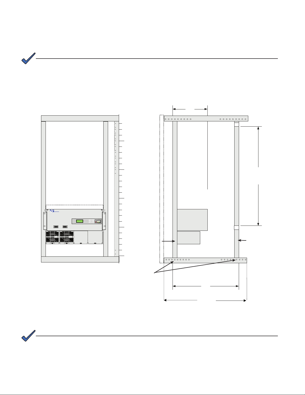
Pad Frame Templates
NOTE:
The illustrations below show the overall size of the pad frame template for a single MiniBay enclosure. The
actual outer dimensions of the pad will be determined by the customer’s requirements. When placing the pad,
allow at least 36 inches of clearance for the front and rear doors to open fully.
29.25"
Front Rear
25.00" Ref.
Front Rear
25.82"
4.0"
(2 places)
4.0"
(2 places)
Fig. 4-4, Pad Frame Template for Single MiniBay Cabinet
Front
42
Rear
Fig. 4-5, Isometric View, Pad Frame Template, Single MiniBay
(P/N 604-039-N1)
044-001-C0-003, Rev. C
Page 43

4.0 SitePreparation,continued
4.3 Pour-in-placeConcretePads,continued
Pad Frame Templates
The illustration below shows the various components of the optional modular pourin-place pad template for a dual-cabinet application. Use template to easily and
accurately locate the open area for the AC service and TSC conduit as well as the
threaded inserts to which the cabinet is attached.
Base Pad Frame Template
(P/N 604
-039
-N1)
Side Chamber Conduit Locator
P/N 745-333-20
Fig. 4-6, Isometric View, Pad Frame Template, Single MiniBay with Side Chamber
Template for Second Enclosure.
Locator Bar for Second Pad FrameTemplate
Locator Bar for Second Pad Frame Template
Base Pad Frame Templ
(P/N 604-039-N1)
P/N 745-332-20
ate
Side Chamber Conduit Locator
P/N 745
-333-20
Fig. 4-7, Isometric View, Pad Frame Template, Dual MiniBay with Side Chamber
43044-001-C0-003, Rev. C
Page 44

4.0 SitePreparation,continued
4.3 Pour-in-PlaceConcretePads,continued
Pad Frame Templates
Figure 4-7 (below) provides the necessary dimensions to layout and pour a concrete
pad on site.
5-
2
3/4"
PL
1-
2
1/8"
PL
5-7/8" 2 PL
5-3/4" 2 PL
7/8" 2 PL
2
2
5
PL
"
SWEEP OPENING
see Section 4.0 Note
2
3-
PL
1
/
2
"
Front of MiniBay
E
TING
UN
2 PL
TH TEMPLAT
USED W I
ES
OL
UND H
L
RO
OBROUNDS USED FOR STUD MO
P
24-1/8" 2
7/8" 2 PL 7/8"
SWEEP OPENING
see Section 4.0 Note
4-1/8"
PAD
FRONT OF
30" 30" 12-1/2"
2-1/8" 2 PL 2-1/8" 2 PL
12-1/2"
44
2-
1/8"
1-
3/8"
1-
3
/
8
3
2
"
"
2-
1
/
8
"
Fig. 4-8, Footprint of Dual Enclosure, Dual Side Chamber System
(dimensions in inches)
044-001-C0-003, Rev. C
Page 45

4.0 SitePreparation,continued
4.4 SiteConguration
Figure 4-9 (below) shows the cable conduit route into the side chamber.
Front
of
Enclosure
C
D
E
A
B
C
D
E
A
B
PRE-CAST PAD
Precast Polymer Pad
Compacted Gravel (12" depth recommended
Level Grade
Area of Backlled Soil
Trench for Sweep (sweep enters back of cabinet)
Fig. 4-9, Typical Site Arrangement, (cabinet with optional side chamber)
NOTE:
Verify the conduit is trimmed 1" to 2" above the pad surface (for side chamber), or 1" to 4" for riser.
45044-001-C0-003, Rev. C
Page 46

4.0 SitePreparation,continued
4.4 SiteConguration,continued
Figure 4-10 (below) shows the cable conduit route into the back of the enclosure.
Back
C
D
E
A
B
C
A
B
PRE-CAST PAD
Precast Polymer Pad
Compacted Gravel (12" depth recommended
Level Grade
Front
Area of Backlled Soil
D
Trench for Sweep (sweep enters back of cabinet)
E
Fig. 4-10, Typical Site Arrangement, (stand-alone cabinet)
NOTE:
Verify the conduit is trimmed 1" to 2" above the pad surface (for side chamber), or 1" to 4" for riser.
46
044-001-C0-003, Rev. C
Page 47

4.0 SitePreparation,continued
4.5 Enclosure Grounding
NOTE:
Alpha Technologies recommends using the grounding method illustrated below. The grounding method for a
particular site is dependant upon soil type, available space, local codes, NEC (National Electric Code), and
other site-specic characteristics.
NOTE:
It is the responsibility of the installer to ensure the requirements of all applicable national and local codes are
met. Alpha Technologies assumes no responsibility or liability for failure of the installer to comply with the
requirements of all applicable local and national codes.
Lightning Protection (Optional)
• 1/2" x 8' copper ground rod, four places, driven about 2 feet (typical) from the corners of
the pad.
• #2 bare copper wire loop terminated to each ground rod and buried a minimum of 30
inches below grade. Corrosion-proof connections (25+ year life-span) and hardware
suitable for direct burial MUST be used.
• #2 bare copper wire from loop to the enclosure.
• When the electrical supply is a primary service (not a secondary or feeder service) a
#2 bare copper wire must bond the lightning protection loop to the Grounding Electrode
Conductor where they are closest.
• Service Grounding (required), #6 bare copper wire from Service Neutral/Ground Bar with
2 ground rods located 6' apart.
Connection made with Burndy connector
(P/N YGHR58C2W-3 or equivalent)
et
fe
)
2
in
(m
Enclosure Footprint
Terminate at enclosure ground
#2 AWG
Connection made with Burndy connector
(P/N YGHP58C2W-2TN or equivalent)
Fig. 4-11, Suggested Grounding
47044-001-C0-003, Rev. C
Page 48

5.0 Installation
This section describes the procedures for installing the enclosure and preparing it for turn-up and test.
The procedures are comprised of the following steps:
• Cabinet installation
• Battery installation and connection
• Utility power connection
Before installation verify the following:
• All necessary grounding rods and materials are in place.
• Utility power is onsite in accordance with NEC (National Electric Code).
• Review and comply with all local safety practices for working with high-voltage systems.
• All necessary permits and permissions are granted.
• The lifting/transport path is free of obstructions.
To perform the installation procedures, the installer(s) needs to have the following tools and materials
on hand:
• Crane to lift enclosure from shipping pallet and place on pedestal
• Key to enclosure doors (P/N 964-022-10 — Pin Allen type)
• Digital RMS voltmeter
• Torque wrench with insulated handle and 7/16" socket
• 7/16" box-end wrench
• NO-OX or other suitable corrosion inhibiting agent
• Battery Cabling Kit
• Silicone sealant (GE RTV123)
CAUTION!
The enclosure MUST be loosed from the pallet BEFORE lifting the enclosure from the truck and
placing it on the pad. Problems such as broken welds, corrosion, etc., resulting from improper
installation are not covered under warranty.
48
044-001-C0-003, Rev. C
Page 49

5.0 Installation,continued
5.1 Lifting
The enclosure is shipped from Alpha Technologies bolted to a wooden pallet. Follow the
procedure below for lifting and positioning the unit.
NOTE:
Remove the lifting ears after installation. The ears are made of steel and may rust over time.
Installation Procedure:
1. Unbolt the enclosure from the pallet. The bolts fastening the enclosure to the pallet are
located in the feet of the rack/rail assembly. They can be reached through the front and
rear doors of the enclosure or battery module (if applicable).
2. Remove the side chamber cable entry port seal plate (if equipped).
3. Position the 25-year vapor barrier material over the concrete pad, and make all
necessary cutouts.
WARNING!
Do not allow personnel to walk beneath the suspended unit during the lifting operation. Use
steel-toe work shoe protection. Use “hard hats” at all times during this procedure.
CAUTION!
Do not lift the enclosure with the batteries in place.
4. Attach the lifting chain to the lifting ears located in the top of the enclosure. Verify the
adjustable chain links are tightened securely. Also verify the length of the cable between
the liftng ears and the lifting hook (2d) is at least twice the distance (d) between the lifting
ears, and that the lifting angle of the chain is greater than or equal to 60 degrees.
2
DX
D
Fig. 5-1, Enclosure Lifting Arrangement
(without side chamber)
Fig. 5-2, Enclosure Lifting Arrangement
(with optional side chamber in place)
49044-001-C0-003, Rev. C
Page 50

5.0 Installation,continued
5.1 Lifting,continued
NOTE:
Verify the length of the cable between the lifting ears and the lifting hook is at least twice the distance
between the lifting plates and that the lifting angle of the chain is greater than or equal to 60 degrees.
5. Lift the enclosure off of the truck using a winch capable of supporting approximately
500 lb. (227kg).
6. Verify all cabling passing through the enclosure is bundled and maintained within the
cutout area.
7. Position the enclosure above the concrete pad and slowly lower it into position over
the pad’s 1/2" anchor or J-bolts. A 25+ year vapor barrier MUST be used between the
concrete and enclosure base to inhibit moisture ingress and corrosion caused by metalto-concrete contact. The vapor barrier material (such as 30 lb felt, neoprene pond liner,
or heavy grade tar paper) should initially extend at least 6" in all directions around the
perimeter of the enclosure. After the enclosure is in place, the material should be trimmed
close to the enclosure, using the appropriate knife or cutting tool.
8. Secure the enclosure using stainless at washers, lock washers and 1/2" nuts at each
mounting bolt.
NOTE:
To prevent damage, enclosures must be mounted ush with a smooth surface and not over-torqued. The
enclosure must be bolted down to a completely at surface. If the concrete pad is uneven or has bumps,
cracks, or other imperfections, the installer is responsible for correcting these defects prior to installing the
enclosure. Do not caulk the enclosure bottom. Caulking can lead to condensation inside the enclosure.
9. Trim sealing cones to proper diameter for a tight t around cables and reassemble seal
plate assembly.
10. Use suitable cable clamps or ties to secure cables to “ladder bar” (see below).
Cable Lashing Bar
Rear of Battery Drawer
Tamper Switch
50
Fig. 5-3, Rear View of Enclosure (showing lashing bar)
044-001-C0-003, Rev. C
Page 51

5.0 Installation,continued
5.2 Special Instructions for Double-wide Installation
When installing two MiniBay enclosures side-by-side, the units should be lifted independently
as shown in section 5.1. Position the rst unit and remove the lifting ears. Apply gasket
material supplied in gasket kit, Alpha P/N 745-361-20. The gasket material should be in place
before positioning the second unit in order to maintain 3R rainproof integrity (see Fig. 5-4).
When the gasket is in place, position the units together and secure together (8 places) using
the supplied hardware.
Tools Required: 9/16" open-end wrench
9/16" socket and driver
Remove Lifting Ears
Apply Gasket Material
Bolt together using
supplied hardware
Fig. 5-4, Dual Enclosure Installation
51044-001-C0-003, Rev. C
Page 52

5.0 Installation,continued
5.3 Battery Connection
Battery Identication
Each battery contains a DATE CODE usually located on a sticker near the center of the
battery or stamped in white ink near the POS terminal. This date code must be recorded
in the battery’s maintenance log. If batteries other than those installed by Alpha are used,
consult the battery’s manufacturers’ documentation for date code type and placement.
Battery Date Code
Connections for AlphaCell Batteries
Battery Terminal Connections:
Refer to the accompanying Battery Cable Kit (BCK) instructions for battery wiring
arrangement and terminal assembly procedures. During maintenance procedures, refer to the
manufacturers’ specications for the maintenance torque requirements.
Mounting hardware requirements may vary with battery manufacturers. Use only the
hardware recommended by your particular battery manufacturer.
Battery Mounted Fuse Stackup
ForTEL12-105,GNBM12V155,andSMU12-155
Threaded
Battery Post
Fuse
BUSS
Ring Terminal
Isolation Washer
Flat Washer
Lock Washer
Bolt
on fused terminal)
(torque to 75 in-lbs
Inline Fuse Stackup
For AlphaCell–FT
Nut
Flat Washer
Ring Terminal
Fuse
Ring Terminal
BUSS
Isolation Washer
Flat Washer
Lock Washer
Bolt
on fused terminal)
(torque to 75 in-lbs
52
Fig. 5-5, Battery Terminal Connection
044-001-C0-003, Rev. C
Page 53

5.0 Installation,continued
5.4 Connecting to Utility Power
ATTENTION:
Verify electrical codes prior to installation. Codes may vary and contain specic conduit and wire sizes for
connection to the load center. Connection to utility power must be approved by the local utility before installing
the power supply.
Connection Procedure:
1. Locate the service entrance panel on the enclosure. Remove the cover to access
the circuit breaker assembly. If this service panel is to be used as the primary service
entrance, neutral must be bonded to ground by installing the green ground screw
(provided) in the hole in the neutral bus.
2. Remove the knockout located in the service entrance to accept the conduit.
3. Install the conduit nipple into the service entrance via the knockout and secure it using
the appropriate threaded conduit locknut.
4. Locate the two screw terminals (L1 and L2) on the service circuit breaker.
5. Connect one of the incoming Black #6AWG wires to L1 (left terminal). Connect the
remaining Black (or Red) #6AWG wire to L2 (right terminal).
NOTE:
If the wire at L2 is black, place red tape (or label) on it.
NOTE:
The enclosure is equipped with a Square D, rainproof load center box (SUSE rated). The service entrance is
equipped for a 120/240VAC, split phase, 3-wire with ground source.
6. Connect the #6AWG White wire to the neutral (N) bus lug located to the top right of
the circuit breaker assembly.
7. Connect the #2AWG stranded copper ground wire (Earth Ground) to the ground and
neutral bus located to the right side of the circuit breaker assembly.
8. Notify the electrical inspector to approve the service entrance wiring. Once approved,
contact the local power utility for electrical service.
53044-001-C0-003, Rev. C
Page 54

5.0 Installation,continued
ON
OFF
ON
OFF
ON
OFF
ON
OFF
Optional AC Generator
`
Enclosure
Load Breakers
Meter
Grounded Conductor
(Neutral)
Ground Bar
Neutral
Line 1
Line 2
ON
OFF
OFFONOFF
ON
OFFONOFF
ON
OFFONOFF
Optional AC Generator
`
Meter
Service Entrance
Enclosure
Load Breakers
ON
Neutral
Ground Bar
Ground Bar
Neutral
5.4 ConnectingtoUtilityPower,continued
Enclosure as Service Entrance
Line 1
Line 2
Groun
Neutral
d
Legend
:
54
Fig. 5-6, Service Entrance Wiring
Line 1
Line 2
Groun
utra
Ne
Legend
:
d
l
044-001-C0-003, Rev. C
Page 55

Appendix A
CSA Marks
®
NRTL/C
CSA International (CSA) was established in 1919 as an independent testing laboratory in
Canada. In 1994, OSHA granted CSA Nationally Recognized Testing Laboratory (NRTL)
status in the United States of America. This was extended in 1999. When these marks
appear with the indicator “C and US” or “NRTL/C” it means that the product is certied for
both the U.S. and Canadian markets to the applicable U.S. and Canadian standards.(1)
ArgusRectierandPowerSystemproductsbearingtheCSANRTL/CMarkare
certiedtoCSAC22.2No.950andUL1950.
®
As part of the reciprocal U.S./Canada agreement regarding testing laboratories, Standards
Council granted Underwriters Laboratories (UL) authority to certify products manufactured
in the U.S. for sale in Canada.
C US
Only Underwriters Laboratories may grant a license for the use of this mark which indicates
compliance with both Canadian and U.S. requirements. (2)
Go to: http://www.osha.gov for more information.
®
C
US
What are NRTLs and what do they do?
NRTL’s are third party organizations recognized by OSHA, U.S. Department of Labor under the NRTL Program.
The testing and certications are based on product safety standards developed by the U.S.-based standards
developing organizations and often issued by ANSI.(3)
The NRTL determines that a product meets the requirements of an appropriate consensus based product safety
standard either by successfully testing the product itself, or by verifying that a contract laboratory has done so.
The NRTL certies that the product meets the requirements of the product safety standard.(4)
WhenwastheNRTLstarted,andwhogovernsit?
In 1983, in a suit brought on by an independent testing laboratory, OSHA
was court ordered to remove specic references to UL (Underwriters
Laboratories) and FRMC (Factory Mutual Research Corporation).
OSHA
In 1988, OSHA revised its regulations to remove those references and the
NRTL program was established.
The NRTL program is both national and international in scope with foreign
labs permitted. As of Dec. 17, 1998, 17 recognized labs were permitted,
with pending applications from 21 other labs.(5)
®
References:
Information presented has been developed from the ofcial web sites of the respective organizations. Specic
references are as follows:
(1) www.csa-international.org/english/product_services/index_cert.htm
(2) www.ul.com/mark/ulmark.htm
(3) www.osha-slc.gov/dts/otpca/nrtl/slide02.html
(4) www.osha-slc.gov/dts/optca/nrtl/slide04.html
(5) www.osha-slc.gov/dts/optca/nrtl/slide18.html
NRTL
Pr
ogram
NRTL/C
®
15 Others
Dec. 17, 1998
55044-001-C0-003, Rev. C
Page 56

Page 57

Alpha Technologies
Power
Copyright © 2006 Alpha Technologies, Inc. All rights reserved. Alpha is a registered trademark of Alpha Technologies. 044-001-C0-003, Rev. C
Due to continuing product improvements, Alpha reserves the right to change specications without notice.
®
Alpha Technologies
3767 Alpha Way
Bellingham, WA 98226
USA
Tel: +1 360 647 2360
Fax: +1 360 671 4936
Web: www.alpha.com
Alpha Technologies Ltd.
4084 McConnell Court
Burnaby, BC, V5A 3N7
CANADA
Tel: +1 604 430 1476
Fax: +1 604 430 8908
Alpha Technologies
Europe Ltd.
Twyford House
Thorley
Bishop's Stortford
Hertfordshire
CM22 7PA
UNITED KINGDOM
Tel: +44 01279 501110
Fax: +44 01279 659870
Alpha Technologies GmbH
Hansastrasse 8
D 91126 Schwabach
GERMANY
Tel: +49 9122 79889 0
Fax: +49 9122 79889 21
Alphatec, Ltd
P.O. Box 56468
Limassol, Cyprus
CYPRUS
Tel: +357 25 375675
Fax: +357 25 359595
AlphaTEK ooo
Khokhlovskiy Pereulok 16
Stroenie 1
109028 Moscow
RUSSIA
Tel: +7 495 916 1854
Fax: +7 495 916 1349
Alphatec Baltics
S. Konarskio G. 49
Vilnius 2009
LITHUANIA
Tel: +350 5 210 5291
Fax: +350 5 210 5292
Alpha Technologies
5 Avenue Victor Hugo
F 92140 Calmart France
FRANCE
Tel: +33 3 41 90 07 07
Fax: +33 1 41 90 93 12
 Loading...