

Page 1
PWE-SG Series
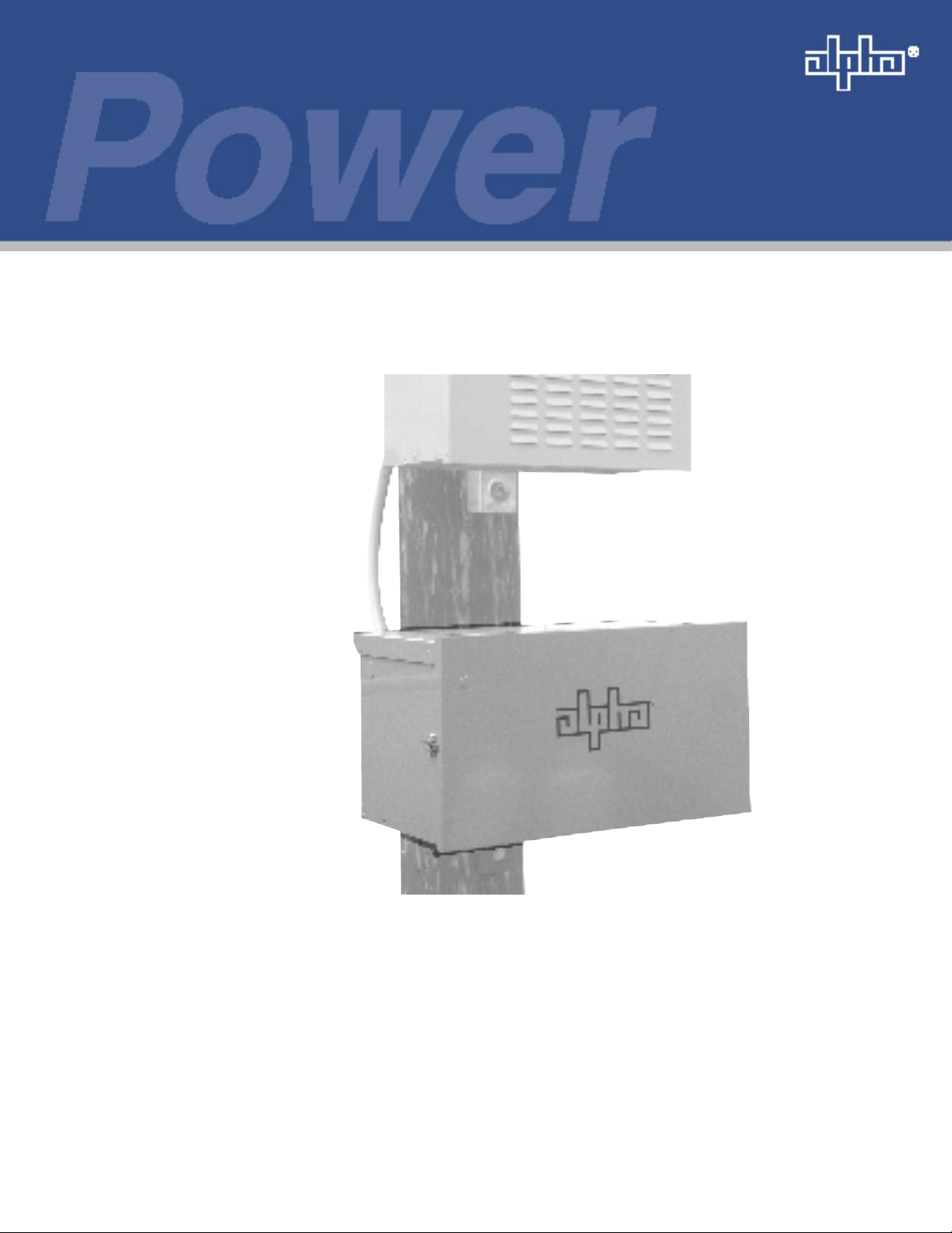
Pole Mount Battery Expansion Enclosure
Installation Manual
Pole Mount Battery Expansion Enclosure
Effective: April 2006
Alpha Technologies
Page 2

Alpha Technologies
Power
®
Page 3

PWE-SG Series
Battery Expansion Pole Mount Enclosure
Installation Manual
Effective Date: April 2006
Copyright© 2006
Alpha Technologies, Inc.
member of The Group
NOTE:
Photographs contained in this manual are for illustrative purposes only. These photographs may not match
your installation.
NOTE:
Operator is cautioned to review the drawings and illustrations contained in this manual before proceeding. If
there are questions regarding the safe operation of this product, please contact Alpha Technologies or your
nearest Alpha representative.
NOTE:
Alpha shall not be held liable for any damage or injury involving its enclosures, power supplies, generators,
batteries, or other hardware if used or operated in any manner or subject to any condition not consistent with
its intended purpose, or is installed or operated in an unapproved manner, or improperly maintained.
TM
Contacting Alpha Technologies: www.alpha.com
or
For general product information and customer service (7 AM to 5 PM, Pacic Time), call
033-090-C0-001, Rev. A
1-800-863-3930,
For complete technical support, call
1-800-863-3364
7 AM to 5 PM, Pacic Time or 24/7 emergency support
3
Page 4

Table of Contents
Safety Notes........................................................................................................................................................6
1.0 Introduction ............................................................................................................................................ 8
1.1 PWE-SG Enclosure Description ............................................................................................... 8
1.2 Enclosure Specications .......................................................................................................... 9
1.3 Accessing the Enclosure ........................................................................................................ 10
1.3.1 Removing the Enclosure Lid ...................................................................................... 10
1.3.2 Operating the Optional Battery Trays ........................................................................ 10
1.4 Optional Features ....................................................................................................................11
2.0 Installation ........................................................................................................................................... 12
2.1 Wooden Pole Installation, Attaching the Brackets .................................................................. 12
2.1.1 Using Optional Brackets ............................................................................................ 14
2.2 Steel/Concrete Pole Installation ............................................................................................. 14
2.3 Grounding the Enclosure ........................................................................................................ 15
2.4 Assembling the Conduit .......................................................................................................... 16
2.5 Connecting to the Legacy (Upper) Enclosure ......................................................................... 19
2.6 Installing PWE-SG Enclosure Batteries .................................................................................. 20
2.6.1 Battery Terminal Connections .................................................................................... 20
2.6.2 Battery Assembly for Vertical Battery Posts .............................................................. 21
2.6.3 Installation Procedure ................................................................................................ 21
2.6.4 Battery Assembly for Front Terminal Battery Posts ................................................... 22
2.6.5 Battery Installation for Front Terminal Batteries ......................................................... 22
2.6.6 Battery Installation Wiring Diagrams ......................................................................... 23
2.7 Installing Optional Features .................................................................................................... 25
2.7.1 Installing the Tamper Switch ...................................................................................... 25
2.7.2 Installing the Battery Heater Mat to the PWE-SG Enclosure ..................................... 26
3.0 Maintenance ........................................................................................................................................ 27
4
033-090-C0-001, Rev.A
Page 5

Figures
Fig. 1-1, PWE-SG Dimensions .............................................................................................................. 8
Fig. 1-2, Removing the Enclosure Lid ................................................................................................. 10
Fig. 1-3, Operating the Optional Battery Trays .................................................................................... 10
Fig. 2-1, Insert Brackert into Mounting Strap ....................................................................................... 13
Fig. 2-2, Secure Upper Bracket ........................................................................................................... 13
Fig. 2-3, Positioning the Enclosure on the Pole ................................................................................... 13
Fig. 2-4, The Two Point Bracket for Both Concrete and Wooden Poles .............................................. 14
Fig. 2-5, The Two Point Extended Bracket for Wooden Pole Mount Enclosures................................. 14
Fig. 2-6, Enclosure Grounding ............................................................................................................. 15
Fig. 2-7, Conduit Placement, Interior View .......................................................................................... 16
Fig. 2-8, Conduit Connector ................................................................................................................ 17
Fig. 2-9, Attaching Anderson Connectors to Battery Cables ............................................................... 18
Fig. 2-10, Receptacle for Battery Heater Mat Line Cord ..................................................................... 18
Fig. 2-11, Attaching Connector ............................................................................................................ 18
Fig. 2-12, Conduit in Place .................................................................................................................. 18
Fig. 2-13, Legacy Enclosure Battery Wiring ........................................................................................ 19
Fig. 2-14, Date Code for Alpha Batteries after September 2001 ......................................................... 20
Fig. 2-15, In-line Fuse Link Mounting .................................................................................................. 20
Fig. 2-16, Vertically Mounted Battery Post .......................................................................................... 21
Fig. 2-17, Typical Ring Lug Assembly for Front Terminal Batteries, Single Lug .................................. 22
Fig. 2-18, 36V Battery Wiring Diagram ................................................................................................ 23
Fig. 2-19, 48V Battery Wiring Diagram ................................................................................................ 23
Fig. 2-20, 2X 36VFT Battery Wiring Diagram ...................................................................................... 24
Fig. 2-21, 1X 48VFT Battery Wiring Diagram ...................................................................................... 24
Fig. 2-22, Tamper Switch Jumper Board, Legacy Enclosure ............................................................... 25
Fig. 2-23, Tamper Switch Installation ................................................................................................... 26
Fig. 2-24, Attaching Battery Heating Mat Line Cord to Side of Enclosure ........................................... 26
Table 1-2, Enclosure Specications ....................................................................................................... 9
033-090-C0-001, Rev. A
Tables
5
Page 6

Safety Notes
Review the drawings and illustrations contained in this manual before proceeding. If there are any questions
regarding the safe installation or operation of the system, contact Alpha Technologies or the nearest Alpha
representative. Save this document for future reference.
To reduce the risk of injury or death, and to ensure the continued safe operation of this product, the following
symbols have been placed throughout this manual. Where these symbols appear, use extra care and
attention.
ATTENTION:
The use of ATTENTION is only for specic regulatory/code requirements that may affect the placement of
equipment and installation procedures.
NOTE:
A NOTE gives readers additional information to help them complete a specic task or procedure.
CAUTION!
The use of CAUTION indicates safety information intended to PREVENT DAMAGE to material or
equipment.
WARNING!
A WARNING presents safety information to PREVENT INJURY OR DEATH to the
technician or user.
6
033-090-C0-001, Rev.A
Page 7

Important Safety Instructions
WARNING!
The temperature of the batteries located in the PWE-SG may differ from those located in the •
legacy enclosure containing the power supply. The design of the PWE-SG minimizes this
difference when the two enclosures are subjected to the same ambient. Always place the battery
temperature sensor, ocntrolling the battery temperature charge compensation, on the hottest
battery. This is typically the center battery located directly below the power supply in the legacy
enclosure.
Lead-acid batteries generate explosive gases. To prevent arcing or burning near batteries, do •
not disconnect DC charging cord from batteries when the charger is operating. Switch the AC
breaker and the DC breaker to the "OFF" position before disconnecting the DC output cord from
the batteries.
Always shield eyes when working near batteries. Do not put wrenches or other metal objects •
across the battery terminal or battery top. Arcing or explosion of the battery can result.
Batteries produce hydrogen gas, which explodes if ignited. Never smoke, use an open ame, •
or create sparks near the battery. Ventilate the area when the battery is charging in an enclosed
place.
Lead-acid batteries contain sulfuric acid, which may cause burns. Do not get acid in eyes, on •
skin, or clothing. If contact with the eyes occur, ush immediately with clean water for 15 minutes
and seek medical attention.
033-090-C0-001, Rev. A
7
Page 8
1.0 Introduction
The PWE-SG is a stand-alone pole mount battery enclosure that supports several battery
congurations and increases the capacity of your existing enclosure systems.
The PWE-SG is a exible and complementary addition to your legacy enclosure and comes with a full
range of options, including a battery drawer, battery heater mat, and a tamper switch.
1.1 PWE-SG Enclosure Description
The enclosure specications vary depending on the battery congurations used in the PWE-
SG. See Table 1-2.
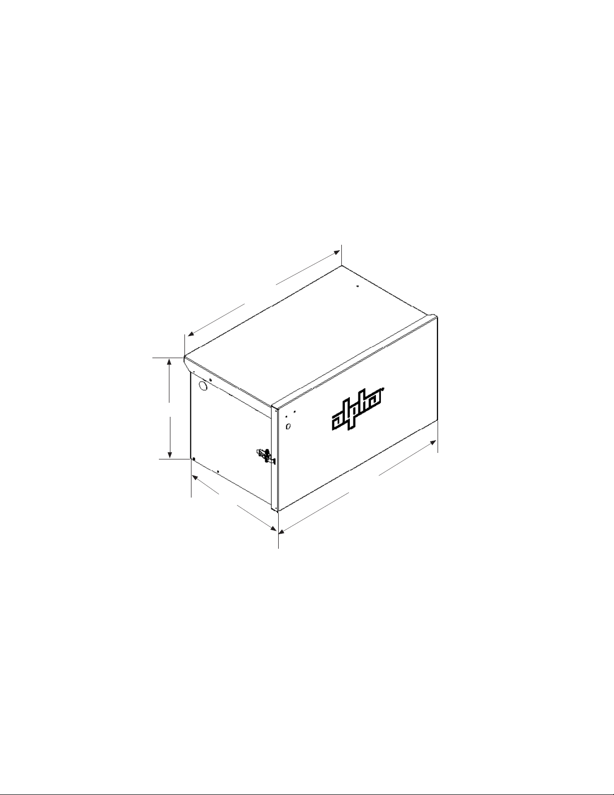
30 1/4"
16 1/4"
17"
Fig. 1-1, PWE-SG Dimensions
30 3/4"
8
033-090-C0-001, Rev.A
Page 9

1.0 Introduction, continued
1.2 EnclosureSpecications
PWE-SG Component Description
Enclosure
Material
Hardware
Color
Tamper Switch
Safety Ground
Lid
Doors
Sliding Battery Drawer
Enclosure Mounting
Gem Lock Kit
Conduit Collocation Kit
Enclosure Environmental
Ratings
Battery Congurations
Battery Retaining Bar
Battery Cable Kits
Battery Heater Mats
Regulatory
PWE-SG: 30.25” (76.83cm) W x 16.25” (41.27cm) H x 17.0” (43.18cm) D, Weight: 31.0 lbs (14.1 Kg)
(Alpha P/N 033-090-20)
Powder-coated aluminum
Stainless steel (excluding optional GemLocks)
Gray (Custom colors available)
Optional
NC, with Printed Circuit Board (PCB) jumper (Alpha P/N 745-851-20)•
NO, with PCB jumper (Alpha P/N 745-851-21)•
Bronze stud (Alpha P/N 744-422-20). Optional stainless steel ground available
Removable lift off
Hinged lift-off removable with stainless steel spring latch. Available with optional door-open prop rod
(Alpha P/N 745-857-20); Gemlock options
Aluminum. Two available options with lock in and lock out slides
Standard option (Alpha P/N 745-088-24) Select if battery weight is less than 300 lbs.•
Heavy duty option (Alpha P/N 745-088-23) Select if battery weight is more than 300 lbs and •
less than 420 lbs.
Galvanized steel brackets for wall, wood and concrete pole mount.
2 Pole mount brackets (PMB) concrete (Alpha P/N 591-557-20)•
Single 2-point PMB (Alpha P/N 605-352-N2)•
8 inch extension 2-point PMB (Alpha P/N 605-360-N2) •
2 PMB wooden (Alpha P/N 744-670-20)•
2 Wall mount brackets (Alpha P/N 744-800-20)•
Provides additional security for enclosure (Alpha P/N 744-229-20)
6" to 24" separation, 48" uncut length of conduit (Alpha P/N 745-853-20)
NEMA 3R
165/185/210 AlphaCell (3 or 4 with or without sliding drawer)•
195/255 AlphaCell FT (3, 4 or 6 without sliding drawer)•
Tel12-125 (3 or 4 with or without sliding drawer)•
Other congurations can be supported•
All AlphaGuard battery congurations•
Secures batteries within the enclosure. (Alpha P/N 745-154-20)
Optional
7' extension with all Battery Cable Kits (BCK) (Alpha P/N 875-584-20)•
Heavy Duty (HD), Fused (F), 1 x 36/1 x 48 AlphaCell FT (195/225) 3 or 4 batteries installed •
(Alpha P/N 745-759-20)
HD/F 2 x 36 AlphaCell FT (195/22) (Alpha P/N 745-759-21)•
HD 1 x 36 AlphaCell (165/180/210) (Alpha P/N 874-202-20)•
HD/F 1 x 36 AlphaCell (165/180/210) (Alpha P/N 874-202-21)•
HD/F 1 x 48 AlphaCell (165/180/210) (Alpha P/N 874-845-20)•
HD 1 x 48 AlphaCell (165/180/210) (Alpha P/N 874-845-21)•
Optional
120VAC with slide tray (Alpha P/N 189-031-10)•
240VAC with slide tray (Alpha P/N 189-031-11)•
120VAC no slide tray (Alpha P/N 189-072-10)•
240VAC no slide tray (Alpha P/N 189-072-11)•
8' line cord extension for 120VAC battery heater mat (BHM) (Alpha P/N 745-854-20)•
8' line cord extension for 240VAC BHM (Alpha P/N 745-854-21)•
CSA C22.2 No. 107.1-01, CSA C22.2 No. 0-M91, CSA C22.2 No. 0.4-04,
CSA C22.2 No. 94-M91, UL 50, UL 1778
033-090-C0-001, Rev. A
Table 1-2, Enclosure Specications
9
Page 10

1.0 Introduction, continued
1.3 Accessing the Enclosure
1.3.1 Removing the Enclosure Lid
1
2
Pull out.
1
2
Pull up.
3
3
Lid rentention strap helps
prevent damage to the
enclosure during servicing.
Fig. 1-2, Removing the Enclosure Lid
1.3.2. Operating the Optional Battery Trays
Opening the tray:
To open, push tray latch in and pull tray out.
Tray automatically locks in the “open” position.
1. Press In
Closing the tray:
Press in
2. Pull Out
To unlock and close tray, press lock in toward tray
and push tray closed.
When returned to the “closed” position, tray
automatically locks back into place.
10
Fig. 1-3, Operating the Optional Battery Tray
033-090-C0-001, Rev.A
Page 11

1.0 Introduction, continued
1.4 Optional Features
Options are either factory installed or can be easily installed in the eld.
NOTE:
A detailed list of all options, including their Alpha part numbers are listed in Table 1-2, Enclosure
Specications.
Battery Heater Mat
The battery heater mat is an AC line operated 150W heater mat which turns on at 40°F to
increase battery capacity in cold environments. Battery mats are available in 120VAC and
240VAC versions.
Tamper Switch (NC/NO)
The Tamper Switch provides a magnetic door switch that plugs into the USM option for XM
power supplies and USM2 for XM Series 2 power supplies. Most status monitoring systems
provide an alarm if the enclosure door is opened. Tamper Switches are available either as
normally open (NO) or normally closed (NC).
Gemlock Kit
Additional security option for the enclosure.
Sliding Battery Trays
There are two types of sliding battery trays available:
Standard slide tray for weights no greater than 300 lbs. See Fig. 1-2 for operation •
instructions.
Heavy duty slide tray for weights greater than 300 lbs and less than 420 lbs. •
As an added safety precaution, the PWE-SG series battery drawer latch holds the battery tray
securely in place in both closed and open positions. The latch automatically locks in place
when the tray is returned to the enclosure.
Battery Cable Kits
A variety of cable kits are available to t your specic application. See Table 1-2 for a
complete list of available kits.
Two Point Mounting Bracket
An optional two point mounting bracket is available to replace the two single galvanized pole
mounting brackets. There is an 8 inch extension bracket also available.
Battery Retaining Bar
The Battery Retaining Bar secures the batteries within the enclosure.
033-090-C0-001, Rev. A
11
Page 12

2.0 Installation
CAUTION!
Do not install the batteries before you mount the enclosure. Transporting the unit with the batteries
in place may cause injury or damage to the enclosure and to the installed equipment.
NOTE:
The majority of poles are the property of the local utility. Have the location and method of mounting approved
before proceeding with the installation. Also, since most local codes require the base of the enclosure to be
located a minimum distance from the ground, verify any height restrictions before installing the enclosure.
Installation Overview:
Mounting the enclosure involves these basic steps:
Attaching the brackets.The procedure varies depending on whether you are installing the 1.
enclosure on a concrete or wooden pole.
Mounting the enclosure.2.
Grounding the enclosure.3.
Placing the wiring in the conduit and attaching the conduit between the enclosures.4.
Installing and wiring the batteries.5.
Installing any optional features, such as a tamper switch or battery heater mat.6.
2.1 Wooden Pole Installation, Attaching the Brackets
NOTE:
The optimal distance between the enclosures is between 6 and 24 inches. Do not mount the enclosures more
than 2 feet apart.
Materials required:
Two 5/8" diameter machine bolts (UNC thread); SAE (Grade 5 or better) length to suit •
pole.
Two 5/8" diameter zinc-plated at washers•
Two 5/8" diameter hex nuts (UNC thread)•
Tools required:
Auger or drill for boring 3/4" diameter holes in the wooden pole•
Mallet or hammer•
Assorted sockets or wrenches•
12
033-090-C0-001, Rev. A
Page 13

2.0 Installation, continued
2.1 Wooden Pole Installation, continued
Procedure:
Unpack the enclosure and galvanized brackets; turn 1.
the enclosure facedown on a soft surface.
Slide one bracket up through the lower mounting 2.
straps on the rear of the enclosure. The bracket's
anges face away from the enclosure. Secure the
lower mounting brackets using the 3/8" x 3/4" hex
bolt. See Fig. 2-1.
Mark the position for the upper mounting bracket on 3.
the utility pole. Drill a 3/4" hole completely through
the pole. Secure the bracket with a 5/8" machine bolt,
washer, and nut. Do not fully tighten the bolt at this
time. See Fig. 2-2.
Position the enclosure on the upper mounting 4.
bracket. It may be necessary to slightly rock the
enclosure and pull downward to properly seat it on
the bracket. Center the enclosure on the pole. See
Fig. 2-3.
Mark the hole for the lower mounting brackets. Lift 5.
the enclosure off the top bracket and drill the lower
hole.
Fig. 2-1, Insert bracket
into mounting strap
Fig. 2-2, Secure upper bracket
Slide the enclosure back into place over the top bracket. Align the lower bracket with the 6.
hole and secure it with a 5/8" machine bolt, washer, and nut. Both enclosure mounting
straps must rest securely on the brackets. Tighten both brackets until the anges seat
into the wood. See Fig. 2-3.
The next step is assembling and attaching the conduit to connect the new PWE-SG 7.
enclosure to the legacy enclosure.
Fig. 2-3, Positioning the enclosure on the pole
NOTE:
Mounting bolts must go completely through the wooden pole and be secured from the back with a large
washer and nut.
033-090-C0-001, Rev. A
13
Page 14

2.0 Installation, continued
2.1 Wooden Pole Installation, continued
2.1.1 Using Optional Brackets
There are two bracket variations available:
The two point bracket (p/n 605-352-N2)*•
The two point 8" extended bracket (p/n 605-360-N2)•
Fig. 2-4, The two point bracket for
both concrete and wood poles
*This bracket can be used for both wooden and concrete poles. It provides additional exibity
and, because utility companies often charge to drill holes in local utility poles, you can save
costs by using both bolts and straps to attach the enclosure. Follow the directions for wooden
and concrete pole installation to install these brackets.
NOTE:
There must be no more than two feet separating the stand-alone generic enclosure from the existing
enclosure. The recommended optimal distance between enclosures is between 6 and 24 inches.
Fig. 2-5, The two point extended bracket
for wood pole mount enclosures
2.2 Steel/Concrete Pole Installation
Materials required:
Two customer-supplied pole straps to t pole. Straps must be stainless, galvanized, or
the equivalent.
Tools required:
Assorted sockets and wrenches
Procedure:
Follow Steps 1 and 2 in the wooden pole mounting instructions.1.
Position the upper mounting bracket on the pole and secure using a pole strap.2.
Lift the enclosure on the upper mounting bracket and pull downward to properly seat it. 3.
Center the enclosure on the pole. See Fig. 2-3.
Secure the lower mounting brackets on the pole using a pole strap. Both enclosure 4.
mounting straps must rest securely on the brackets.
The next step to connect the new enclosure to the existing enclosure is assembling and 5.
running the conduit to connect the new enclosure to the primary battery enclosure.
14
033-090-C0-001, Rev.A
Page 15

2.0 Installation, continued
2.3 Grounding the Enclosure
Alpha Technologies recommends using the grounding method illustrated here. The grounding
method for a particular site is dependent upon available space, local codes, the National
Electric Code (NEC), and other site-specic characteristics.
ATTENTION:
Alpha Technologies assumes no responsibility or liability for the failure of the installer to comply with the
requirements of all applicable local and national codes.
Conduit to existing pole mount enclosure
PWE-SG Enclosure
033-090-C0-001, Rev. A
Fig.2-6, Enclosure Grounding
15
Page 16

2.0 Installation, continued
2.4 Assembling the Conduit
The conduit contains the battery cables and the wiring for other optional features, such as the
tamper switch or battery heater mat. It is used to connect the stand-alone enclosure to the
power supply located in the existing enclosure.
The conduit kit, supplied with the PWE-SG, consists of a sufcient length of weather-sealed
exible conduit and two connectors.
WARNING!
Before proceeding with the placement and wiring of the batteries and optional
features, turn off the battery breaker and remove all battery connections from
the power supply. Use insulated tools and secure all loose cable ends to
prevent inadvertent unattended connections.
Procedure:
Locate the knockout in the the upper left corner of the PWE-SG enclosure. Using a 1.
rubber mallet, clear the hole for the conduit.
Drill a similar hole in the legacy enclosure:2.
Remove the far left battery to provide access a.
Place the hole in the upper left corner of the legacy enclosure, below the equipment b.
tray, and clearing both the tray and any wiring already in place. See Fig. 2-7
Using a 1 3/8" hole saw, drill a hole that will accommodate 1 inch conduit. c.
Measure the distance between the drilled and knockout holes, adding 6 inches to the 3.
measurement to account for needed exibility, and cut conduit to size.
Hole containing conduit
wiring
Drill hole to
accommodate
conduit
16
Fig. 2-7, Conduit Placement, Upper Enclosure Interior View
033-090-C0-001, Rev.A
Page 17

2.0, Installation, continued
2.4 Assembling the Conduit, continued
NOTE:
Always run the lines and battery cables from the top end of the conduit toward the end which will be
connected to the PWE-SG (bottom) enclosure.
Install a conduit connector to the end of the conduit which will be installed in the legacy 4.
(upper) enclosure. Remove the plastic locknut. See Fig. 2-8.
Cut conduit to lengtha.
Insert conduit through plastic screw ringb.
Insert conduit into connector. Tighten with the plastic screw ring.c.
Before you can proceed to step 5, threading the battery cables and additional d.
wiring through the connector, you must rst remove the plastic locknut.
b
a
d
Fig.2-8, Conduit Connector
If you are not installing optional features, thread the battery cables through the conduit 5.
starting at the end of the conduit which will be attached to the legacy enclosure.
If you are installing a tamper switch or battery heater mat, you must add those wires to
the conduit before you insert the battery cable. It is important to thread the other optional
wires and battery cables through the conduit in the proper order.
First to install a tamper switch,◊ insert the magnet end of the tamper switch line
into the conduit.
Second to install a battery heater mat◊ , insert the un-terminated end of the line
cord for the battery heater mat into the conduit.
Next◊ , insert the end of the battery cables containing the contacts for the
Anderson connectors into the conduit.
Remove the plastic locknut and attach the lower conduit connector (Fig. 2-8) at the 6.
knockout hole. On the inside of the lower enclosure, thread the plastic locknut through
the wiring and using channel locks carefully tighten the plastic locknut, sealing the black
rubber O-ring securely against the enclosure. (Fig. 2-11)
c
033-090-C0-001, Rev. A
17
Page 18

2.0, Installation, continued
2.4 Assembling the Conduit, continued
In the PWE-SG enclosure, using the provided Anderson connectors, terminate the battery 7.
cable. See Fig. 2-9.
If you are installing a battery heater mat, terminate the battery heater mat line cord with 8.
the receptacle provided. See. Fig. 2-10
Green to ground
White or blue to silver contact
Fig. 2-9, Attaching Anderson
Connectors to Battery Cables
Black or brown to gold contact
Fig. 2-10, Receptacle for
Battery Heater Mat Line Cord
Carefully run the upper wires through the drilled hole in the legacy enclosure. 9.
Using the plastic locknut, attach the upper conduit connector. Use channel locks to 10.
carefully tighten the connector, sealing the black rubber O-ring securely against the
enclosure. See Fig. 2-11
The conduit is in place. Optimally, the conduit connectors should be swiveled to 45°F. 11.
See Fig. 2-12.
18
Black O-ring secured
against enclosure
Fig. 2-11, Attaching Connector
Fig. 2-12, Conduit in Place
033-090-C0-001, Rev.A
Page 19

2.0 Installation, continued
2.5 Connecting to the Legacy (Upper) Enclosure
Replace the battery you removed in Section 2.4, Step 2. Referring to Fig. 2-13, hook up the
battery strings.
Using the battery
cables from the
conduit, hook up
the battery string.
The cables will be
co-terminated.
Fig. 2-13, Legacy Enclosure Battery Wiring
Close the battery tray, keeping the wires clear. To install a tamper switch, see Section 2.8 for
instructions.
033-090-C0-001, Rev. A
19
Page 20

2.0 Installation, continued
2.6 Installing PWE-SG Enclosure Batteries
CAUTION!
Before you install batteries, please read the Safety Notes at the beginning of this manual.
Each battery contains a date code, which is usually located near the positive (+) terminal of
the battery. Record this code in the maintenance log. If batteries, other than those supplied
by Alpha are used, consult the manufacturer's documentation of the date code type and
placement.
Month: June. (06)
Year: 2005 (05)
NOTE:
The date code label format and location may vary depending on the age of the battery being used.
Fig. 2-14, Date Code for Alpha Batteries after September 2001.
CAUTION!
If you are installing a battery heater mat, it must be installed prior to the batteries. See Section 2.7
for instructions on installing the heater mat.
2.6.1 Battery Terminal Connections
Always refer to the battery manufacturer's instructions for correct mounting hardware
and torque requirements for installation as well as maintenance specications.
NOTE:
While the use of an in-line fuse is optional, Alpha recommends the use of the fuse in all installations.
Mounting hardware requirements vary with different manufacturers. Use the
appropriate hardware for your battery type. The following photo and drawing are for
illustrative purposes only.
Battery Terminal
Spacer
Battery Cable, and
Crimp Connector to
Next Battery
20
In-line Fuse Link
Washers and Nut
Figure 2-15, In-line Fuse Link Mounting
033-090-C0-001, Rev.A
Page 21

2.0 Installation, continued
2.6 Battery Installation, continued
2.6.2 Battery Assembly for Vertical Terminal Battery Posts
This is the typical battery terminal assembly for vertically mounted battery posts.
Refer to the battery manufacturers' specications for tightening torque.
Figure 2-16, Vertically Mounted Battery Post
2.6.3 Installation Procedure
CAUTION!
Do not let live battery cables contact the chassis when you are making or breaking battery
connections. If necessary, wrap the lugs with electrical tape to prevent arcing and temporarily
disconnect one of the leads from the center battery. Ensure the battery string voltage and polarity
are correct.
Place the batteries, with the positive terminals oriented toward the front of the 1.
enclosure, on the battery slide tray or shelf. Maintain as much ventilation space
between batteries as possible.
Number each battery and record the number and date code in the maintenance 2.
log. This aids in indentication and future record keeping.
Connect the batteries in series to achieve the correct voltage. See the battery 3.
wiring diagrams on page 22. If you are using the optional in-line fuse, connect it
to the positive terminal of the battery located farthest to the right. For AlphaCell
batteries, terminal connectors must be torqued to approximately 65 inch/pounds
at installation and then re-torqued to 50 inch/pounds during routine maintenance.
Use a voltmeter to verify polarity and DC voltage at the module's battery 4.
connector.
Plug the battery cable connector into the battery cable connector from the conduit 5.
kit.
NOTE:
The cables have a red sleeve to denote the (+) positive battery terminal. When using multiple battery strings,
the in-line fuse is recommended.
033-090-C0-001, Rev. A
21
Page 22

2.0 Installation, continued
2.6 Battery Installation, continued
2.6.4 Battery Assembly for Front Terminal Battery Posts
Below is the typical battery terminal assembly for front terminal battery posts. Torque
rating for all terminals in 60-in-lbs (6.5nM).
Bolt
Lock Washer
Flat Washer
Ring Terminal
Threaded Battery Post
Fig. 2-17, Typical Ring Lug Assembly for Front Terminal Batteries, Single Lug
2.6.5 Battery Installation for Front Terminal Batteries
Place the batteries, with the terminals oriented toward the front of the enclosure. 1.
Use the battery manufacturer's recommended spacing between batteries for
maximum ventilation.
Number the batteries using labels or masking tape and record each battery's 2.
number and date code in the maintenance log. This helps in future record
keeping and identication.
Connect the batteries in series to achieve 36VDC or 48VDC. 3.
Verify battery polarity and install battery jumper bars after attaching all terminals 4.
to respective terminal posts. Use a voltmeter to verify polarity and DC voltage at
the module's battery connector.
Plug the battery cable connector into the battery cable connector from the conduit 5.
kit. See page 23 for battery wiring diagrams.
NOTE:
The cables are marked with a RED sleeve to indicate the (+) positive battery terminal.
22
033-090-C0-001, Rev.A
Page 23

2.0 Installation, continued
2.6 Battery Installation, continued
2.6.6 Battery Installation Wiring Diagrams
To existing battery string
Connectors from conduit kit
Black (-)
Black (-) Red (+)
Red (+)
In-Line Fuse (optional)
Fig.2-18, 36V Battery Wiring Diagram
To existing battery string
Connectors from conduit kit
In-Line Fuse (optional)
033-090-C0-001, Rev. A
Fig. 2-19, 48V Battery Wiring Diagram
23
Page 24

2.0 Installation, continued
2.6 Battery Installation, continued
2.6.6 Battery Installation Wiring Diagrams, continued
To existing battery string
Connectors from conduit kit
Black (-)
Red (+)
1A
1B 2B 3B
2A
3A
In-line Fuse (optional)
Fig. 2-20, 2X 36VFT Battery Wiring Diagram
To existing battery string
Connectors from conduit kit
24
Red (+)Black (-)
1A
2A
3A
Fig. 2-21, 1X 48VFT Battery Wiring Diagram
In-line Fuse (optional)
4A
033-090-C0-001, Rev.A
Page 25

2.0 Installation, continued
2.7 Installing Optional Features
NOTE:
The instructions in this section presuppose that you have already placed the appropriate lines in the conduit.
This is a pre-requisite for installing these features. See Section 2.4 for information on assembling the conduit.
2.7.1 Installing the Tamper Switch
The tamper switch provides a magnetic door switch which plugs into the power
supply. Most status monitoring systems provide an alarm if the enclosure door is
opened. Tamper switches are available as normally open (NO) or normally closed
(NC). See Table 1-2 for part numbers and additional information.
In the legacy enclosure:
Using the velcro provided, attach the tamper switch jumper board to the right wall 1.
of the enclosure. See Fig. 2-22.
Unplug the existing tamper switch from the power supply and plug it into the 2.
tamper switch jumper board.
Plug in the new tamper switch extension (coming from the conduit) into the 3.
tamper switch jumper board. Make sure to coil and zip-tie excess wire.
Plug the new tamper switch jumper cable into both the tamper switch jumper 4.
board and the power supply.
Fig. 2-22, Tamper Switch Jumper Board, Legacy Enclosure
Tamper Switch
Jumper Board
033-090-C0-001, Rev. A
25
Page 26

2.0 Installation, continued
2.7 Installing Optional Features, continued
2.7.1 Installing the Tamper Switch, continued
In the PWE-SG enclosure:
Using a hand rivet gun with 5/32" nosepiece, attach the tamper switch bracket to 1.
the left front ange of the enclosure. See. Fig. 2-23.
Screw the new tamper switch (from the conduit) to the bracket, using the screws 2.
provided.
Attach the magnet to the door of the enclosure using the nuts provided.3.
Attach tamper switch bracket
Fasten wires to bracket
Fig. 2-23, Tamper Switch Installation
2.7.2 Installing the Battery Heater Mat to the PWE-SG Enclosure
NOTE:
You must install the battery heater mat before placing the batteries in the enclosure.
If necessary, extend battery tray and add the heater mat to the bottom of the tray 1.
or the enclosure.
Replace the battery tray and plug in the line cord to the cord/receptacle from the 2.
conduit kit.
Tamper switch magnet
Using tie straps, secure the line cord to the upper left side of the enclosure to 3.
CAUTION!
avoid moisture.
Take care to attach the battery heater mat line cord to the side of the enclosure with tie straps. It is
important to avoid moisture. See Fig. 2-24.
Fig.2-24, Attaching Battery Heating Mat Line Cord to Side of Enclosure
26
Line cord secured to
side of enclosure.
033-090-C0-001, Rev.A
Page 27

3.0 Maintenance
Establishing a routine of regular, preventative maintenance ensures the pole mount enclosure will
function for many trouble-free years.
Every three to six months:
Inspect the enclosure.•
Check for signs of rust and corrosion, paying particular attention to the battery trays. Clean any
rust or corrosion immediately.
Inspect the mounting brackets and hardware.•
Carefully check for signs of unusual wear and loose hardware. Correct any deciencies
immediately.
Check battery terminals and connecting wires.•
Care of the batteries is essential to any maintenance program. In addition to voltage checks,
visually inspect the batteries for signs of cracking, leaking, or swelling. To aid in quick
identication and tracking of voltages in the maintenance log, use labels to number the batteries
inside the enclosure. Batteries are temperature sensitive and susceptible to overcharging and
undercharging. Since batteries behave differently in winter than in summer, Alpha's battery
chargers automatically compensate for changes in temperature by adjusting oat and accept
charge voltages.
See the power supply's maintenance manual for instructions on maintaining the power supply.
Check each battery terminal and connection. Verify the posts are clean and the crimped
connectors are tight. Terminal connectors must be torqued to specication at installation and
then re-torqued to 50 inch/pounds during routine maintenance. If there is an "in-line" fuse in
the battery cable, check the fuse holder and fuse. Verify terminals are properly greased with an
approved battery terminal corrosion inhibitor such as NCP-2. Record date of maintenance in the
maintenance log.
Check battery open circuit voltage.•
Switch the power supply's battery breaker to the OFF position. Disconnect the battery connector
from the inverter module andmeasure the individual voltage across each battery. The difference
between any battery in the string must not be greater than 0.3 VDC. Defective or marginal
batteries must be replaced with an identical type of battery. Record the unloaded battery voltages
in the maintenance log.
NOTE:
Whenever the power supply's battery breaker is turned OFF or the batteries are disconnected, the power
supply will not operate in inverter mode in the event of a utility power failure.
033-090-C0-001, Rev. A
27
Page 28

Alpha Technologies
Power
®
Alpha Technologies
3767 Alpha Way
Bellingham, WA 98226
USA
Tel: +1 360 647 2360
Fax: +1 360 671 4936
Web: www.alpha.com
Alpha Technologies Ltd.
4084 McConnell Court
Burnaby, BC, V5A 3N7
CANADA
Tel: +1 604 430 1476
Fax: +1 604 430 8908
Alpha Technologies
Europe Ltd.
Twyford House Thorley
Bishop's Stortford
Hertfordshire CM22 7PA
UNITED KINGDOM
Tel: +44 0 1279 501110
Fax: +44 1 279 659870
Alpha Technologies GmbH
Hansastrasse 8
D 91126 Schwabach
GERMANY
Tel: +49 9122 79889 0
Fax: +49 9122 79889 21
Alphatec, Ltd
339 St. Andrews Street
Suite 101 Andrea Chambers
3307 Limassol
CYPRUS
Tel: +357 25 375675
Fax: +357 25 359595
AlphaTEK ooo
Khokhlovskiy Pereulok 16
Stroenie 1 Ofce 403
109028 Moscow
RUSSIA
Tel: +7 495 916 1854
Fax: +7 495 916 1349
Alphatec Baltic
S. Konarskio Street G.49-201
Vilnius LT-03123
LITHUANIA
Tel: +370 5 210 5291
Fax: +370 5 210 5292
Alpha Technologies
34, Grande Rue
Bétheny, F-51450
France
Phone: +33 32 64990 54
Fax: +33 67 54289 44
Copyright © 2006 Alpha Technologies, Inc. All rights reserved. Alpha is a registered trademark of Alpha Technologies. 033-090-C0-001 Rev. A.
Due to continuing product improvements, Alpha reserves the right to change specications without notice.
 Loading...