

Page 1
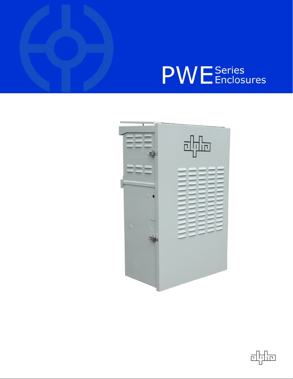
PWE Battery Enclosure (BE)
Field Upgrade Installation
Effective: October, 2002
Manual
®
Page 2

Alpha Technologies.
Protecting The Power in Communications.
Power
Page 3

®
PWE Battery Enclosure (BE)
Field Installation Manual
Preface
033-077-C0-002 Rev. B
October, 2002
Copyright © 2002
Alpha Technologies, Inc
NOTE: This manual covers the installation of the PWE Battery Enclosure. Always
work with the local utilities when connecting the enclosure to these utilities
and observe all local and national laws which may be applicable for your area.
NOTE: Photographs contained in this manual are for illustrative purposes only. These
photographs may not exactly match your installation.
NOTE: Review the drawings and illustrations contained in this manual before
033-077-C0-002 Rev. B
proceeding. If there are questions regarding the safe installation and
operation of this enclosure or powering system, please contact Alpha
Technologies or your nearest Alpha representative.
3
Page 4

Preface
Table of Contents
1.1 BE Installation ................................................................. 9
1.1.1. BE Kit Contents ........................................................ 10
1.1.2. Mounting Bracket Installation ...................................... 11
1.1.3. Rain Guard Installation ............................................... 13
1.1.4. Enclosure Installation ................................................ 14
1.1.5. Battery Installation ................................................... 15
1.1.6 Cable Installation ...................................................... 16
1.1.7 Final Assembly .......................................................... 17
1.1.8 Completed Assemblies ................................................ 18
List of Figures
Fig. 1-1 Placing Template .................................................................... 11
Fig. 1-2 Bracket Installation ................................................................ 12
Fig. 1-3 Cabinet With Lid and Door Removed .......................................... 12
Fig. 1-4 Installing Rain Guards.............................................................. 13
Fig. 1-5 Mounting BE Enclosure ............................................................ 14
Fig. 1-6 Battery and RTS Placement, Connection .................................... 15
Fig. 1-7 Cable Routing ........................................................................ 16
Fig. 1-8 Lid and Door in Place .............................................................. 17
Fig. 1-9 Grounding Lug ....................................................................... 17
4
033-077-C0-002 Rev. B
Page 5
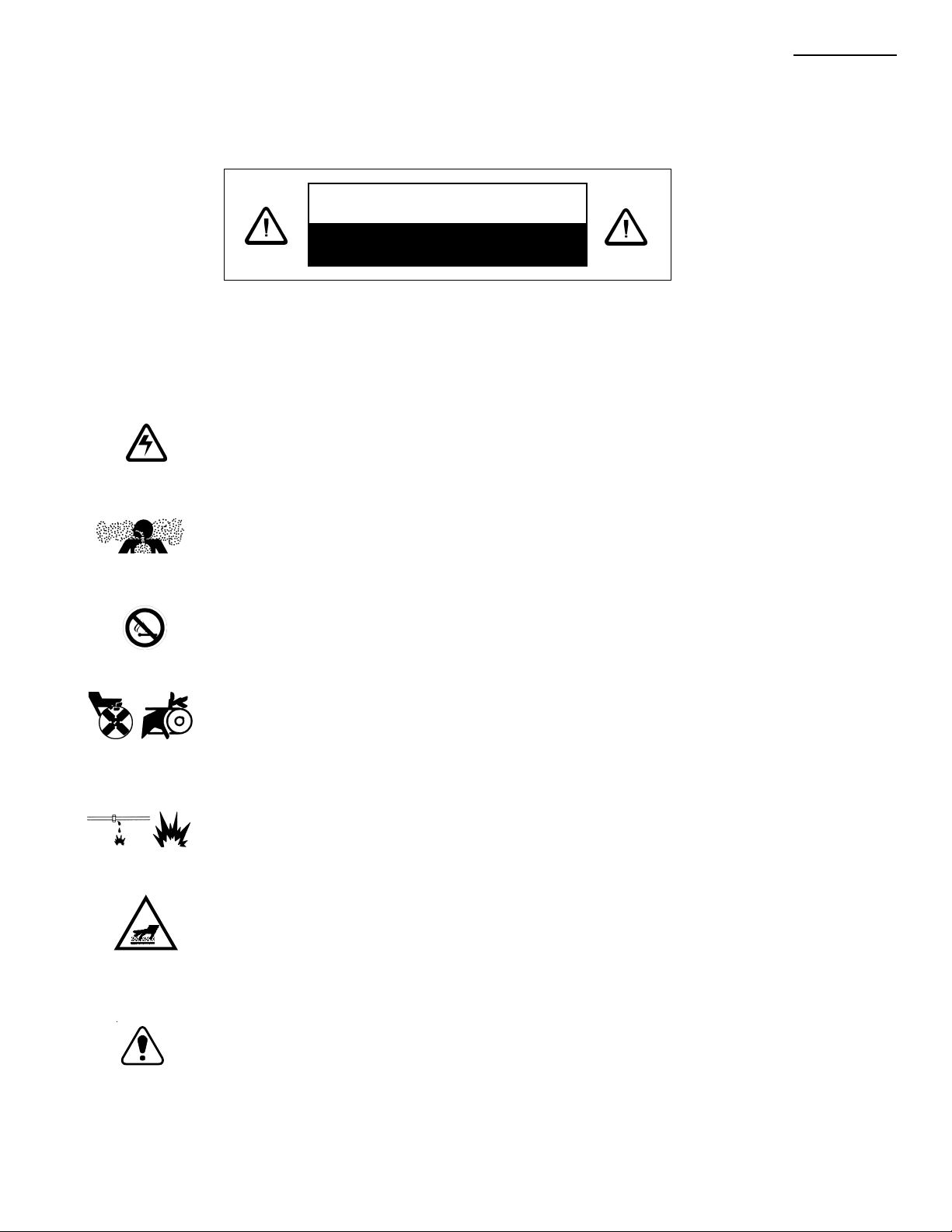
IMPORTANT SAFETY INSTRUCTIONS
CONTAINED IN THIS MANUAL
CAUTION
HAZARDOUS CONDITION
To reduce the risk of electrical shock, injury or death caused by explosion of
fuel or moving parts, and to ensure the safe operation of this unit, the
following symbols have been placed throughout the manual. Where these
symbols appear, servicing should be performed only by qualified personnel.
DANGEROUS VOLTAGE
This symbol indicates a “dangerous voltage” exists in this area of the
product. Use caution whenever working in the area to prevent
electrical shock.
Preface
INHALATION HAZARD - DON’T BREATHE VAPORS
This symbol indicates an “inhalation hazard” exists in this area of the
product. Use caution whenever working in the area to prevent possible
inhalation of harmful (fuel or exhaust) vapors.
NO MATCHES OR OPEN FLAMES
This symbol indicates a fire or explosive hazard exists in this area of
the product. Use caution whenever working in the area to prevent
possible combustion fuel vapors.
MECHANICAL OR MOVING PARTS HAZARD
These symbols indicate the presence of a “mechanical or moving parts
hazard” in this area of the product. Use caution whenever working in
the area to prevent possible injury to the operator or servicepersonnel.
LEAK HAZARD
This symbol indicates a “leak hazard” exists in this area of the product.
Use caution whenever working in the area to prevent and correct any
leaks detected.
HOT SURFACES
This symbol indicates the presence of high temperatures which result
from the operation of the system. To prevent burns, do not touch
these areas while the system is in operation or immediately after it has
been turned off.
033-077-C0-002 Rev. B
ATTENTION
This symbol indicates important installation, operation or maintenance
instructions. Always follow these instructions closely.
5
Page 6

Preface
SAFETY PRECAUTIONS
• The system must be serviced only by qualified personnel.
• Remove all rings, watches and other jewelry before servicing
batteries or servicing the system.
• Always use proper lifting techniques whenever handling units,
modules or batteries.
• If batteries are being stored prior to installation, they should be
charged at least once every three months to ensure optimum
performance and maximum battery service life.
• The battery pack, used to provide backup power, contains dangerous
voltages. Battery inspection and replacement must be performed by
qualified personnel.
• Always wear protective clothing, insulated gloves and eye protection
(i.e. safety glasses or a face shield) whenever working with batteries.
• Always carry a supply of water, such as a water jug, to wash the eyes
or skin in the event of exposure to battery electrolyte.
• Do not allow live battery wires to contact the enclosure chassis.
Shorting battery wires can result in a fire or possible explosion.
• Batteries must be inspected every three to six months for signs of
cracking, leaking or swelling.
• Always replace batteries with those of an identical type and rating.
Never install old or untested batteries.
• Avoid using uninsulated tools or other conductive materials when
handling batteries or working inside the enclosure.
• Spent or damaged batteries are considered environmentally unsafe.
Always recycle used batteries or dispose of in accordance with all
Federal, State, and local regulations.
6
033-077-C0-002 Rev. B
Page 7

Battery Safety Notes
Chemical Hazards
Any gelled or liquid emissions from a Valve-Regulated Lead-Acid (VRLA)
battery is electrolyte which contains dilute sulfuric acid which is harmful to
the skin and eyes; is electrically conductive; and is corrosive.
If electrolyte contacts the skin, wash immediately and thoroughly with water.
If electrolyte enters the eyes, wash thoroughly for 10 minutes with clean
water or a special neutralizing eye wash solution and seek immediate medical
attention.
Neutralize any spilled electrolyte with the special solutions contained in a “spill
kit” or with a solution of 1 lb. Bicarbonate of soda to 1 gal. of water.
Fire, Explosion, and Heat hazards
Lead acid batteries can contain an explosive mixture of hydrogen gas which
can vent under overcharging conditions.
Do not smoke or introduce sparks in the vicinity of the battery.
Prior to handling the batteries, touch a grounded metal object, such as the
rack, to dissipate any static charge that may have developed in your body.
Do not charge batteries in a sealed container. If contained, assure the
container or cabinet and room have adequate ventilation to prevent an
accumulation of potentially dangerous gas.
Preface
033-077-C0-002 Rev. B
7
Page 8

Preface
IMPORTANT INSTALLATION NOTES
The system must be installed ONLY by qualified service personnel.
ALPHA TECHNOLOGIES is not responsible for broken welds or other damage to
the cabinet caused by improper installation.
All dimensions are given in inches.
For further information regarding this installation, contact ALPHA
TECHNOLOGIES or your nearest ALPHA representative.
For general product information and Customer Service
7:00AM to 5:00PM Pacific Time
1-800-863-3930
To obtain complete Technical Support,
7:00AM to 5:00PM Pacific Time
or
For after-hours Emergency support
7 days per week, 24 hours a day
1-800-863-3364
NOTE:
Alpha Technologies’ products are subject to change
through continual improvement processes. Therefore,
specifications and/or design layouts may vary slightly
from descriptions included in this manual. Updates to the
manual will be issued when changes affect form, fit or
function.
Save these instructions for future reference
8
033-077-C0-002 Rev. B
Page 9

1.1 BE Installation
Overview
The PWE Battery Enclosure was designed to allow the customer to
add additional batteries in the field for additional standby/run time.
Upon receipt, the enclosure should be unpacked and inspected for
shipping damage. The following items should be enclosed:
1. Battery Enclosure (Alpha P/N 033-077-20)
2. Battery Cable ‘Y’ Adapter (Alpha P/N 874-655-20)
3. Battery Cable Kit (Alpha P/N 874-202-21)
4. Pole Mounting Bracket
5. Bracket Hole Drilling Template
6. New PWE Door
7. New PWE Lid
8. Rain Guards
9. Mounting Hardware
1. Installation
Tools and Materials Needed:
Digital Volt-Ohm Meter
Hand Operated Rivet Gun with .156” nosepiece
3/4” Drill Motor
3/4” Auger Bit (long enough to drill through pole)
7/16” Wrenches and Sockets
Torque Wrench
3 Batteries (manufacturer and type to match existing batteries)
NOTES:
The total combined weight of a fully-populated PWE and BE is
approx. 600 pounds. Verify stability of the mounting pole before
installation.
Secure permission of pole owner for mounting of enclosure.
Obtain, review, and follow all appropriate electrical, building and
installation codes and practices of the local area and utilities.
Verify lifting equipment is safe and capable of weight requirements.
Verify area around, above and below is clear of all obstructions
which may pose a hazard during installation.
Post necessary hazard warnings for the work area.
9033-077-C0-002 Rev. B
Page 10

1. Installation
1.1 BE Installation, continued
1.1.1. BE Kit Contents
Listed below each version of PWE are the parts required for each
installation. All extra parts may be disposed of.
New PWE Type II PWE Type I PWE
Battery Enclosure (A) Battery Enclosure (A) Battery Enclosure (A)
Rear Rain Guard (B) Door (C) Door (C)
Door (C) Drilling Template (D) Drilling Template (D)
Drilling Template (D) Mounting Bracket (E) Mounting Bracket (E)
Mounting Bracket (E) Side Rain Guards (F)
Rubber Bumpers (G)
A PWE-BE
B Rear Rain Guard
R
C Door
D Drilling Template
E Mounting Bracket
Left Right
F Side Rain Guards
10
G Rubber Bumpers
033-077-C0-002 Rev. B
Page 11

1. Installation
1.1 BE Installation, continued
1.1.2. Mounting Bracket Installation
WARNING: Follow all manufacturer’s operating and safety instructions for
the use of power tools and punch drivers. Set BATTERY
BREAKER on the power supply to the OFF position.
Secure service power to the enclosure for the duration of
the installation.
1. Place the drilling template on top of the upper pole bracket, and
hold flush against the pole. Use the upper hole for the New
PWE, and the lower hole for the Type I and Type II PWE.
13 1/2"
12 1/2"
Fig. 1-1 Placing Template
2. Mark the hole location, and remove the template. Drill a 3/4” hole
through the pole.
11033-077-C0-002 Rev. B
Page 12

1. Installation
1.1 BE Installation, continued
1.1.2. Mounting Bracket Installation, continued
3. Install the mounting bracket using a 1/2” bolt, washers, and nut.
12.5" or 13.5" REF.
18" REF.
Fig. 1-2 Bracket Installation
2. Remove the PWE door and lid.
12
Fig. 1-3 Lid and Door Removed
033-077-C0-002 Rev. B
Page 13

1.1 BE Installation, continued
1.1.3. Rain Guard Installation
1. If required, rivet the rain guards to the PWE-BE enclosure.
2. Using a #19 drill bit (0.166”), drill out the rivet hole ‘dimples’ on
the sides or rear of the enclosure. Install the rain guards with
the rivets included in the PWE-BE kit.
1. Installation
REAR VIEW LEFT SIDE VIEW
Fig. 1-4 Installing Rain Guards.
13033-077-C0-002 Rev. B
Page 14

1. Installation
1.1 BE Installation, continued
1.1.4. BE Mounting
1. Remove the lid from the PWE, and set aside. For New PWE,
attach bumpers to the upper door jams (see drawing below).
Align the pole mount strap on the PWE-BE with the mounting
plate on the pole. Lower the BE enclosure onto the top of the
PWE. Verify the flange on the bottom of the BE enclosure
fits over the OUTSIDE of the PWE enclosure on both sides and
the back. Tighten the retaining bolt on the PWE-BE pole mount
strap to secure the BE enclosure to the mounting plate.
Place rubber 'bumpers' in the slots
located on the sides of the New Style
PWE enclosure.
14
Fig. 1-5 Mounting BE Enclosure
033-077-C0-002 Rev. B
Page 15

1.1 BE Installation, continued
1.1.5. Battery Installation
1. Remove the BE enclosure lid, and hang to the side on the
lanyard. Install three batteries as shown below. Attach Battery
Cable Kit and remote temperature sensor according to the
diagram.
2. Using a multimeter, verify that the battery pack has at least
36 VDC at the connector. Verify polarity is correct (red = pos,
black = neg)
1. Installation
---
+++
Temp Sensor
POS
NEG
Fig. 1-6 Battery and TRS Placement and Connection
15033-077-C0-002 Rev. B
Page 16

1. Installation
1.1 BE Installation, continued
1.1.6. Cable Connections
1. Verify the BATTERY BREAKER on the power supply is in the OFF
position. Unplug the existing battery pack and RTS from the
front of the power supply.
2. Plug the ‘Y’ adapter into the front of the power supply.
Connect both battery packs to the remaining plugs of the ‘Y’
adapter.
16
Power Supply
Fig. 1-7 Cable Routing
033-077-C0-002 Rev. B
Page 17

1.1 BE Installation, continued
1.1.7. Final Assembly
1. Reinstall the BE enclosure lid
2. Install the new front door
3. Run a new #6 solid copper grounding wire from the grounding
lug on the back of the BE enclosure to the grounding rod at the
base of the pole (Fig. 1-9).
1. Installation
Fig. 1-9 Grounding Lug
Fig. 1-8 Door and Lid In Place
17033-077-C0-002 Rev. B
Page 18

1. Installation
1.1 BE Installation, continued
1.1.8. Completed Assemblies
New PWE
Type II PWE
Type I PWE
18
033-077-C0-002 Rev. B
Page 19

Page 20

www.alpha.com
Protecting The Power in Communications.
Power
Corporate
Alpha Technologies
3767 Alpha Way
Bellingham, WA 98226
USA
Tel: (360) 647-2360
Fax: (360) 671-4936
Web: www.alpha.com
Alpha Technologies Ltd.
4084 McConnell Court
Burnaby, BC, V5A 3N7
CANADA
Tel: (604) 430-1476
Fax: (604) 430-8908
Alpha Technologies
Europe Ltd.
Cartel Business Estate
Edinburgh Way
Harlow, Essex CM20 2TT
UNITED KINGDOM
Tel: +44-1279-422110
Fax: +44-1279-423355
Alpha Technologies
Hansastrasse 8
D-91126 Schwabach
GERMANY
Tel: +49-9122-79889-0
Fax: +49-9122-79889-21
Alphatec
339 St. Andrews Street
Suite 101
Andrea Chambers
Limassol, Cyprus
CYPRUS
Tel: +357-25-375675
Fax: +357-25-359595
Alpha Technologies
Unit R5-R7 Regents Park Estate
Corner Park Rd and Prince’s Rd East
Regents Park, NSW 2143
AUSTRALIA
Tel: +61-2-9722-3320
Fax: +61-2-9722-3321
Copyright © 2002 Alpha Technologies, Inc. All rights reserved. Alpha is a registered trademark of Alpha Technologies. 033-077-C0-002 Rev.B.
Due to continuing product improvements, Alpha reserves the right to change specifications without notice.
 Loading...