

Page 1
PWE-6FT
Pole-mount Enclosure
Installation and Operation Manual
PWE-6FT
Effective: August, 2005
Alpha T echnologies
Page 2

Alpha Technologies
Power
®
Page 3

Installation and Operation
PWE-6FT
Pole-mount Enclosure
031-259-B0-001, Rev A
Effective Date: August, 2005
Copyright© 2005
Alpha Technologies, Inc.
member of the Group
Photographs contained in this manual are for illustrative purposes only . These photographs may not match your
installation.
TM
Operator is cautioned to review the drawings and illustrations contained in this manual before proceeding. If
there are questions regarding the safe operation of this powering system, please contact Alpha T echnologies or
your nearest Alpha represent ative.
Alpha shall not be held liable for any damage or injury involving its enclosures, power supplies, generators,
batteries, or other hardware if used or operated in any manner or subject to any condition not consistent with its
intended purpose, or is installed or operated in an unapproved manner, or improperly maint ained.
Contacting Alpha Technologies: www.alpha.com
OR
For general product information and customer service (7 AM to 5 PM, Pacific Time), call
1-800-863-3930,
For complete technical support, call
1-800-863-3364
7 AM to 5 PM, Pacific Time or 24/7 emergency support
3031-259-B0-001, Rev A
Page 4

T able of Contents
Important Safety Instructions!................................................................................................. 6
1.0 Introduction to the PWE-6FT Enclosure .................................................................... 11
1.1 Specifications................................................................................................ 11
1.2 Optional Features .......................................................................................... 13
2.0 Installation ................................................................................................................ 15
2.1 Wooden Pole Installation ............................................................................... 15
2.2 Steel/Concrete Pole Inst allation...................................................................... 17
2.3 Pedestal and Enclosure Installation................................................................ 19
2.3.1 Pedestal-mount Considerations .......................................................... 19
2.3.2 Pedestal Installation ............................................................................ 20
2.3.3 Installing Enclosure on the Pedestal .................................................... 21
2.4 En closu re Grou nding ..................................................................................... 22
2.4.1 Enclosure Grounding for Pole-mount Configurations ........................... 22
2.4.2 Enclosure Grounding for Pedestal-mount Configurations..................... 23
2.5 Connecting the Utility Power .......................................................................... 24
2.5.1 Wiring the Utility Service ..................................................................... 24
2.5.2 Wiring From Duplex Receptacle to Service Disconnect....................... 25
2.5.3 Connecting Coaxial Cable .................................................................. 30
2.6 Battery Installation.......................................................................................... 32
2.6.1 Battery T erminal Assembly Procedure................................................. 32
2.6.2 Battery Installation Procedure.............................................................. 33
2.7 Power Supply Installation ............................................................................... 34
2.8 Cooling Fan Installation.................................................................................. 35
3.0 Pole-mount Enclosure Maintenance.......................................................................... 36
4 031-259-B0-001, Rev A
Page 5

Figures and T ables
Fig. 1-1, PWE-6FT Views and Dimensions .......................................................11
Fig. 1-2, PWE Enclosure Lid Removal .............................................................. 12
Fig. 2-1, PWE Series Pole-mount Enclosures (Wooden Poles).........................16
Fig. 2-2, PWE Series Pole-mount Enclosures
(Concrete and Steel Poles) ................................................................. 18
Fig. 2-3, Bollard Post Placement.......................................................................19
Fig. 2-4, Pedestal Installation ............................................................................ 20
Fig. 2-5, PWE-6FT Enclosure Mounted to Pedestal .......................................... 21
Fig. 2-6, Enclosure Grounding for Pole-mount Configuration..............................22
Fig. 2-7, Enclosure Grounding for Pedestal-mount Configurations ..................... 23
T able 2-1, Service Entrance Circuit Breaker Requirements.................................. 24
Fig. 2-8, T ypical Service Entrance Wiring .......................................................... 25
Fig. 2-9, Typical Receptacle Wiring...................................................................26
Fig. 2-10, T ypical BQO (Breaker Quad Option) Receptacle Wiring......................27
Fig. 2-1 1, PWE Pole Mount, 240V AC UL Wiring (030-051-C7-A)........................ 28
Fig. 2-12, PWE Pole Mount, 240V AC CSA Wiring (030-051-C8-A) .................... 29
Fig. 2-13, T ypical Ring Lug Assembly for Front Terminal Batteries, Single Lug ..... 32
Fig. 2-14, In-line Fuse Installation........................................................................33
Fig. 2-15, Battery Wiring Diagram.......................................................................33
Fig. 2-16, Cooling Fan Kit Installed......................................................................35
5031-259-B0-001, Rev A
Page 6

Important Safety Instructions!
Review the drawings and illustrations contained in this manual before proceeding. If there are any
questions regarding the safe installation or operation of the system, contact Alpha Technologies or the
nearest Alpha representative. Save this document for future reference.
T o reduce the risk of injury or death caused by electrical shock, explosion of fuel or moving parts; and
to ensure the continued safe operation of this product, the following symbols have been placed
throughout this manual. Where these symbols appear, use extra care and attention.
Symbols in this Manual
The use of ATTENTION is only for specific regulatory/code requirements that may affect the placement of
equipment and installation procedures.
A NOTE gives readers addtional information to help them complete a specific task or procedure.
A CAUTION presents safety information to PREVENT DAMAGE TO ALPHA or CUSTOMER’S EQUIPMENT. A
CAUTION tells you how to correctly perform a procedure or action and what could happen if you fail to follow
the the instructions.
A WARNING presents safety information to PREVENT INJURY OR DEATH to the technician/user. A W ARNING
tells you how to take specific safety precautions and then explains what may happen if those precautions are
not followed.
6 031-259-B0-001, Rev A
Page 7

Alpha T echnologies’ products are subject to change through continual improvement processes. Therefore,
specifications and/or design layouts may vary slightly from descriptions included in this manual. Updates
to the manual will be issued when changes affect form, fit or function.
General Safety Precautions
This enclosure and its associated hardware (power supply , batteries, cabling) may contain equipment,
batteries or parts which have accessible hazardous voltage or currents.
T o avoid injury:
• This enclosure and its associated hardware must be serviced only by authorized personnel.
• Enclosure must remain locked at all times, except when authorized service personnel are
present.
• Remove all conductive jewelry or personal equipment prior to servicing equipment, parts,
connectors, wiring, or batteries.
• Read and follow all installation, equipment grounding, usage, and service instructions included
in this manual.
• Use proper lifting techniques whenever handling enclosure, equipment, parts, or batteries.
• Batteries contain dangerous voltages, currents and corrosive material. Battery installation,
maintenance, service and replacement must be performed by authorized personnel only.
• Never use uninsulated tools or other conductive materials when installing, maintaining,
servicing or replacing batteries.
• Use special caution when connecting or adjusting battery cabling. An improperly connected
battery cable or an unconnected battery cable can result in arcing, a fire, or possible
explosion.
• A battery that shows signs of cracking, leaking or swelling must be replaced immediately by
authorized personnel using a battery of identical type and rating.
• Avoid any contact with gelled or liquid emissions from a valve-regulated lead-acid (VRLA)
battery . Emissions contain dilute sulfuric acid which is harmful to the skin and eyes.
Emissions are electrolytic, which are electrically conductive and are corrosive. Follow the
Chemical Hazards notes if contact occurs.
• Do not smoke or introduce sparks in the vicinity of a battery.
• Under certain overcharging conditions, lead-acid batteries can vent a mixture of hydrogen gas
which is explosive. Proper venting of the enclosure is required.
• Follow the battery manufacturer’s approved transportation and storage instructions.
7031-259-B0-001, Rev A
Page 8

Enclosure, equipment or parts may be damaged or cause damage if used or installed improperly .
T o avoid damage:
• Prior to installation, verify that the AC input voltage to the enclosure and it s equipment match
withrespect to voltage and frequency .
• Prior to installation, verify that the output voltage from the enclosure or its equipment match
the voltage requirements of the connected equipment (load).
• Prior to installation, verify that the enclosure’s utility service panel is equipped with a properly
rated circuit breaker for use with the equipment inside. Refer to manufacturer’s
recommendations.
• Review and upgrade utility service panel circuit breaker requirements whenever the equipment
within the enclosure is changed.
• Prior to installation, contact local utilities, local building maintenance departments, and cable/
piping locator services to ensure that installation does not interfere with existing utility or
building cables/piping.
• Do not exceed the output rating of equipment. Verify load requirement s prior and during
connection process.
• Prior to handling the batteries, touch a grounded metal object to dissipate any static charge
thatmay have developed in your body .
Battery Safety Notes
Lead-acid batteries contain dangerous voltages, currents and corrosive material. Battery installation,
maintenance, service and replacement must be performed only by authorized personnel.
Chemical Hazards
Any gelled or liquid emissions from a valve-regulated lead-acid (VRLA) battery contain dilute
sulfuric acid, which is harmful to the skin and eyes. Emissions are electrolytic, which are
electrically conductive and corrosive.
T o avoid injury:
• Servicing and connection of batteries shall be performed by , or under the direct supervision of,
personnel knowledgeable of batteries and the required safety precautions.
• Always wear eye protection, rubber gloves, and a protective vest when working near batteries.
Remove all metallic objects from hands and neck.
• Batteries produce explosive gases. Keep all open flames and sparks away from batteries.
• Use tools with insulated handles, do not rest any tools on top of batteries.
• Batteries contain or emit chemicals known to the S tate of California to cause cancer and birth
defects or other reproductive harm. Battery post terminals and related accessories contain
lead and lead compounds. Wash hands after handling (California Proposition 65).
• If any battery emission contacts the skin, wash immediately and thoroughly with water. Follow
your company’s approved chemical exposure procedures.
8 031-259-B0-001, Rev A
Page 9

Battery Safety Notes, cont.
• If any battery emission contacts the skin, wash immediately and thoroughly with water . Follow
your company’s approved chemical exposure procedures.
• Neutralize any spilled battery emission with the special solution contained in an approved spill
kit or with a solution of 1 lb. Bicarbonate of soda to 1 gal of water . Report chemical spill using
your company’s spill reporting structure and seek medical attention if necessary .
• Always replace batteries with those of an identical type and rating. Never install old or
untested batteries.
• Do not charge batteries in a sealed container . Each individual battery should have at least 0.5
inches of space between it and all surrounding surfaces to allow for convection cooling.
• All battery compartments must have adequate ventilation to prevent an accumulation of
potentially dangerous gas.
• Prior to handling the batteries, touch a grounded metal object to dissipate any static charge
that may have developed on your body .
• Never use uninsulated tools or other conductive materials when installing, maintaining,
servicing or replacing batteries.
• Use special caution when connecting or adjusting battery cabling. An improperly connected
battery cable or an unconnected battery cable can make contact with an unintended surface
that can result in arcing, fire, or possible explosion.
• A battery showing signs of cracking, leaking, or swelling should be replaced immediately by
Authorized Personnel using a battery of identical type and rating.
• Under extreme overcharging conditions, Lead-acid batteries can vent a mixture of Hydrogen
gas which is explosive.
Battery Maintenance Guidelines
The battery maintenance instructions listed below are for reference only . Battery manufacturer’s
instructions for transportation, installation, storage or maintenance take precedence over these
instructions.
• T o prevent damage, inspect batteries every 3 months for:
Signs of battery cracking, leaking or swelling. The battery should be replaced
immediately by authorized personnel using a battery of the identical type and rating.
Signs of battery cable damage. Battery cable should be replaced immediately by
Authorized Personnel using replacement parts specified by vendor .
Loose battery connection hardware. Refer to battery manufacturer’s documentation
for the correct torque and connection hardware for the application.
• Apply battery manufacturer’s specified antioxidant compound on all exposed connections.
• V erify battery terminals and/or exposed connection hardware is not within 2 inches of a
conductive surface. Reposition batteries as necessary to maintain adequate clearance.
• Clean up any electrolyte (battery emission) in accordance with all federal, state, and local
regulations or codes.
• Proper venting of the enclosure is recommended. Follow the Battery Manufacturer’s approved
transportation and storage instructions.
• Always replace batteries with those of an identical type and rating. Never install old or
untested batteries.
9031-259-B0-001, Rev A
Page 10

Mechanical Safety
• Keep hands and tools clear of fans. Fans are thermostatically controlled and will turn on
automatically.
• Power supplies can reach extreme temperatures under load.
• Use caution around sheet metal components and sharp edges.
Electrical Safety
• Lethal voltages are present within the power supply and electrical boxes. Never assume that
an electrical connection or conductor is not energized. Check the circuit with a volt meter with
respect to the grounded portion of the enclosure (both AC and DC) prior to any installation or
removal procedure.
• Do not work alone under hazardous conditions.
• A licensed electrician is required to install permanently wired equipment.
• Input voltages can range up to 240 V AC. Ensure that utility power is disabled before beginning
installation or removal.
• Ensure no liquids or wet clothes contact internal components.
• Hazardous electrically live parts inside this unit are energized from batteries even when the AC
input power is disconnected from the Mini-Bay .
Recycling and Disposal Instructions
Spent or damaged batteries are considered environment ally unsafe. Always recycle used batteries
or dispose of the batteries in accordance with all federal, state and local regulations.
• Do not charge batteries in a sealed container. Each individual battery should have at least 0.5
inches of space between it and all surrounding surfaces to allow for convection cooling.
• All battery compartments must have adequate ventilation to prevent an accumulation of
potentially dangerous gas.
10 031-259-B0-001, Rev A
Page 11
1.0 Introduction to the PWE-6FT Enclosure
1.1 Specifications
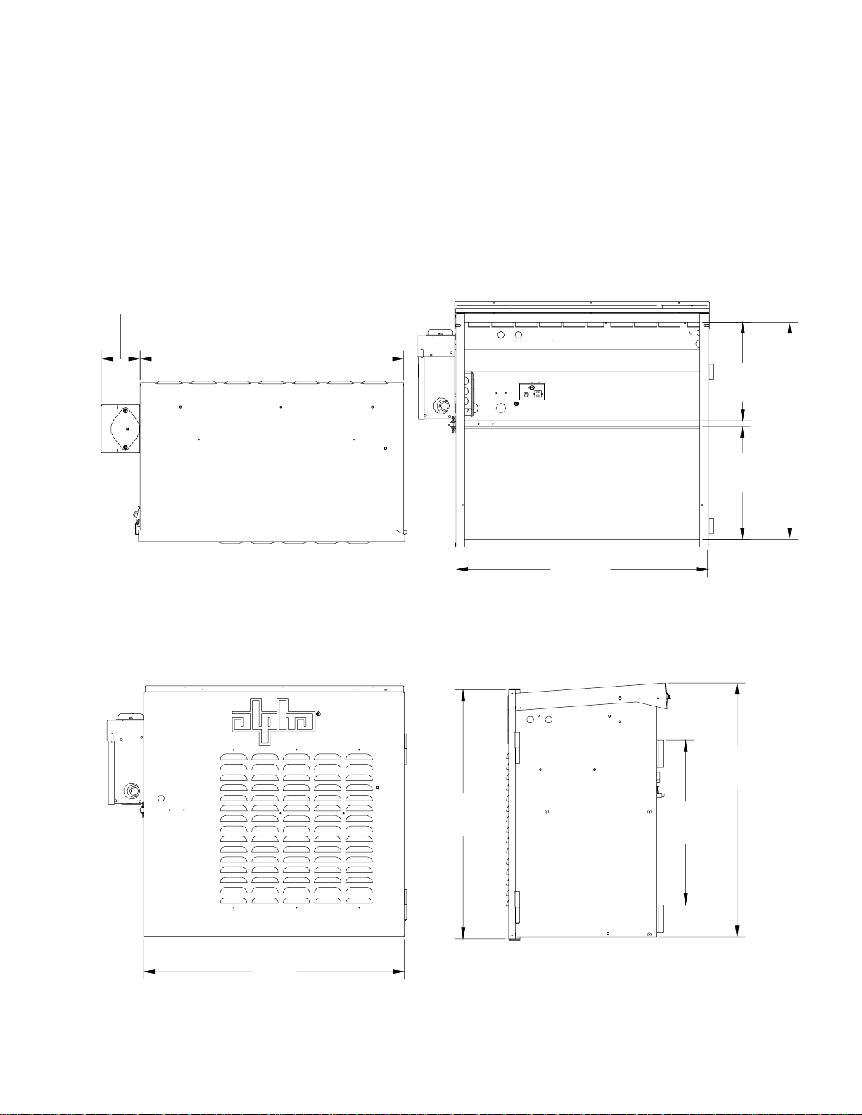
The PWE-6FT enclosure accommodates six front-terminal batteries for broadband powering equipment
in pole-, wall-, or pedestal-mount configurations. The weight of the enclosure (empty) is 57 lbs (26kg).
4.26"
(10.9cm)
29.12"
(74cm)
11.14"
(28.3cm)
24.54"
(62.3cm)
12.78"
(32.5cm)
29.12"
(74cm)
27.46"
(69cm)
28.58"
(72.6cm)
27.76
(70.5cm)
18.0"
(45.7cm)
Fig. 1-1, PWE-6FT Views and Dimensions
11031-259-B0-001, Rev A
Page 12
1.0 Introduction to the PWE-6FT Enclosure, continued
1.1 Specifications, continued
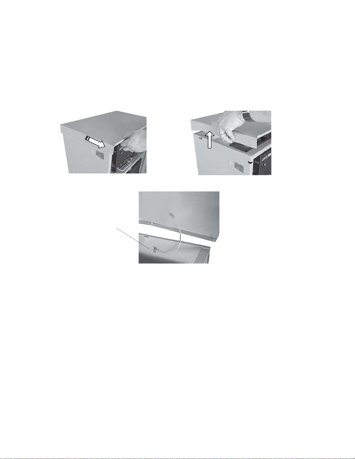
The PWE series of enclosures have removable lids to facilitate installation of internal
components within the enclosure. The following photos are only for illustrative purposes.
PWE Lid Removal
1. Pull Out
Note: Lid can be completely
removed by releasing the provided
wing nut .
2. Pull Up
Lid Retention Strap helps prevent
enclosure lid from damage while
servicing the system.
Fig. 1-2, PWE Enclosure Lid Removal
12 031-259-B0-001, Rev A
Page 13

1.0 Introduction to the PWE-6FT Enclosure, continued
1.2 Optional Features
Options can be factory installed. Many of these options can be easily installed in the field by
the operator.
ACI (AC Indicator)
The AC Indicator (green lamp) is located next to the LRI lamp on the outside of the PWE/PME
Series enclosures. As long as there is volt age present at the output, the ACI lamp remains ON.
The ACI is a simple form of status monitoring which allows the operational status of the power
supply to be verified from the ground. The ACI-LL, long life LED is recommended, since it
provides much longer life than the original incandescent light bulb design. Models for 60V and
90V are available.
BHM (Battery Heater Mat)
The Battery Heater Mat is an AC line operated 150W heater mat which turns on at 40°F to
increase battery capacity in cold environments. BHM are available in 120V AC and 240V AC
versions.
ECF (Enclosure Cooling Fan)
The Enclosure Cooling Fan is a standby powered, thermostat controlled cooling fan system for
maintaining a cooler environment within the PWE Series enclosures. Alpha recommends the
enclosure cooling fan option for installations in extremely high temperature environments. The
fan is thermostatically controlled to turn on at 140°F/60°C, and off at 1 10°F/43°C. Replace the
fan fuse with a 1/4” X 1-1/4”, 5 Amp, 250 Volt fuse only (Alpha P/N 460-025-10).
LA-P+ (Lightning Arrester)
The LA-P+ Lightning Arrester consists of three Metal Oxide V aristors (MOV) and is plugged
directly into the enclosure’s convenience outlet, to provide additional protection from voltage
spikes caused by lightning and other power disturbances. The LA-P+ eliminates the need for
hard-wired MOVs, and no additional wiring is necessary . The LA-P+ 120 is used in 120V AC
applications, and the LA-PE+ 240 is used in 240V AC applications.
LRI (Local Remote Indicator)
The LRI lamp (red) is located on the outside of the PWE/PME Series enclosure. During normal
AC line operation, the lamp remains OFF. The lamp comes ON only when the power supply is
running in S tandby Mode. In the event that a major alarm is detected, the lamp flashes to
indicate service is required. The LRI is a simple form of status monitoring which allows the
operational status of the power supply to be verified from the ground.
MRC (Module Retaining Cable)
The Module Retaining Cable provides added security for the XM Series 2 power supply . It
attaches the unit to the PWE Series enclosure wall to prevent it from being inadvertently
knocked off of its shelf.
SPI (15A Service Power Inserter) and SPI-25 (25A Service Power Inserter)
The Service Power Inserter is required in all enclosures. The primary function of the SPI is to
provide a connection point between the Alpha power supply and the cable load. Additionally the
SPI can be used to bypass the power supply with a Service Power Supply . The SPI is rated for
15 amps output and is standard on the PWE/PME Series enclosures. The SPI-25 is the same
as the SPI but rated for 25 amps for use with higher output current power supplies.
13031-259-B0-001, Rev A
Page 14

1.0 Introduction to the PWE-6FT Enclosure, continued
1.2 Optional Features, continued
STH (Storm Hood Kit)
Enclosures equipped with the optional Storm Hood Kit of fer additional protection from possible
dirt and snow ingress. If the enclosure is equipped with Storm Hoods, Alpha recommends the
use of the ECF (Enclosure Cooling Fan).
TMPR SW (Tamper Switch)
The T amper Switch provides a magnetic door switch which plugs into the USM option for XM
power supplies and the USM2 for XM Series 2 power supplies. Most status monitoring systems
provide an alarm if the enclosure door is opened. Tamper Switches are available either as
normally open (NO) or normally closed (NC).
14 031-259-B0-001, Rev A
Page 15

2.0 Installation
The PWE-6FT can be mounted on wooden, concrete or steel utility poles. Most codes require the base
of the enclosure to be located a minimum height from the ground. Always verify height restrictions before
proceeding.
2.1 Wooden Pole Installation
Never transport the unit with batteries installed. Batteries must ONL Y be installed after the unit
is installed. Transporting the unit with installed batteries may cause injury to installer and/or
damage to enclosure and installed equipment.
Alpha recommends positioning enclosure on the opposite side of the pole from oncoming traffic. This can reduce
the danger caused by falling equipment in the event that a pole is struck by an automobile.
Mounting bolts must go completely through the wooden pole and be secured from the back with a large washer
and nut.
The majority of poles are the property of the local utility company . Before installing an enclosure, the location
and method of mounting must be approved by the utility company .
Materials required: (customer supplied)
• Two 5/8" diameter machine bolts (UNC thread); SAE (Grade 5 or better), length to suit pole
• Two 5/8" diameter zinc-plated flat washers
• Two 5/8" diameter hex nut s (UNC thread)
T ools required: (customer supplied)
• Auger or drill for boring 3/4" diameter holes in the wooden pole
• Mallet or hammer
• Assorted sockets or wrenches
Procedure:
1. Unpack the enclosure and galvanized brackets; turn the enclosure facedown on a soft
surface.
2. Slide one bracket up through the lower mounting straps on the rear of the enclosure. The
bracket’s flanges face away from the enclosure. Secure the lower mounting brackets using
the 3/8" x 3/4" hex bolt.
3. Mark the position for the upper mounting bracket on the utility pole. Drill a 3/4" hole
completely through the pole. Secure the bracket with a 5/8" machine bolt, washer and nut.
Do not fully tighten the bolt at this time.
4. Position the enclosure on the upper mounting bracket. It may be necessary to slightly rock
the enclosure and pull downward to properly seat it on the bracket. Center the enclosure on
the pole.
15031-259-B0-001, Rev A
Page 16

2.0 Installation, continued
2.1 Wooden Pole Installation, continued
5. Mark the hole for the lower mounting brackets. Lift the enclosure off the top bracket and drill
the lower hole. Sp acing between holes for enclosures is as follows:
PWE-6FT 18.0” on center
6. Slide the enclosure back into place over the top bracket. Align the lower bracket with the
hole and secure it with a 5/8" machine bolt, washer and nut. Tighten both brackets until the
flanges seat into the wood.
The enclosure is now ready for the utility connection, power module and batteries.
Upper Mounting Bracket
Nut & Washer
5/8" Bolts
Cable Power Out
ACI, LRI Options
Generator Access Port
Chassis Ground
Utility Power In
18"
3/8" X 3/4" Hex Bolt
Lower Mounting Bracket
Fig. 2-1, PWE Series Pole-mount Enclosures (Wooden Poles)
16 031-259-B0-001, Rev A
Page 17

2.0 Installation, continued
2.2 Steel/Concrete Pole Installation
Never transport the unit with batteries installed. Batteries must ONL Y be installed after the unit
is installed. Transporting the unit with batteries inst alled may cause injury to installer and/or
damage to enclosure and installed equipment.
Alpha recommends positioning enclosure on the opposite side of the pole from oncoming traffic. This can reduce
the danger caused by falling equipment in the event that a pole is struck by an automobile.
The majority of poles are the property of the local Utility . Before installing an enclosure, the location and method
of mounting must be approved by the Utility .
Materials required: (customer supplied)
Two (2) pole strap s to fit pole (straps must be stainless, galvanized or equivalent).
T ools required: (customer supplied)
Assorted sockets or wrenches
Procedure:
1. Unpack the enclosure and galvanized brackets; turn the enclosure facedown on a soft
surface.
2. Slide a bracket up through the enclosure’s lower mounting strap(s). The bracket’s flanges
must face away from the enclosure. Secure the lower mounting bracket(s)
using the 3/8" x 3/4" hex bolt included.
3. Position the upper mounting bracket on the pole and secure using a pole strap.
4. Lift the enclosure onto the upper mounting bracket and pull downward to properly seat it.
Center the enclosure on the pole.
5. Secure the lower mounting brackets on the pole using a pole strap. S pacing between
mounting straps for enclosure is as follows:
PWE-6FT 18.0” on center
The enclosure is now ready for the utility connection, power module and batteries (see following
page).
17031-259-B0-001, Rev A
Page 18

2.0 Installation, continued
2.2 Steel/Concrete Pole Installation, continued
Pole Straps
(Customer Supplied)
18"
Upper Mounting Bracket
Cable Power Out
ACI, LRI Options
Generator Access Port
Chassis Ground
Utility Power In
3/8" X 3/4" Hex Bolt
Lower Mounting Bracket
Fig. 2-2, PWE Series Pole-mount Enclosures (Concrete and Steel Poles)
(Configurations may vary .)
18 031-259-B0-001, Rev A
Page 19

2.0 Installation, continued
2.3 Pedestal and Enclosure Installation
A concrete pad must be in place prior to installing the pedestal. The installer must supply the
following materials to install the pedestal (P/N 745-677-20):
• Four (4) 1/2” anchor bolts (Hilti style-P/N 745-592-21)
• Four (4) 1/2” stainless steel washers
Required tools:
• Hammer drill • Metal punch
• 1/2” drill bit • Mallet or hammer
• 1/2” wrench • Torque wrench
• T ape measure
The following are general considerations to make prior to installing a ground-mounted enclosure:
• Do not install enclosure within 10 feet of a water sprinkler
to prevent water from entering enclosure.
• Ensure the enclosure is outside flood plain boundaries.
• Position the enclosure to prevent wind-driven snow and
drifts from blocking the vents.
• In hot climates, position the enclosure to maximize
afternoon shade.
2.3.1 Pedestal-mount Considerations
Alpha Technologies, Inc. cannot anticipate all of the ways a vehicle may potentially
threaten an installed system or the specific type of protection that is appropriate for a
particular location. Determining the threat to the equipment and the means of protection are the responsibility of the end user of the equipment and the authority having
jurisdiction. The following installation drawing for Alpha’s S tandby Power systems are
general recommendations and not intended to be a specific guideline for protecting the
equipment. The numbers of Bollard posts (or other protection devices) depend upon
equipment locations, site surveys, traffic patterns and local codes.
PAD
POSTS
10' Min.
Sprinkler
Head
SIDEWALK
Fig. 2-3, Bollard Post Placement
19031-259-B0-001, Rev A
Page 20

2.0 Installation, continued
2.3.2 Pedestal Installation
1. Place vapor barrier material on pad. The vapor barrier material (such as 30lb felt,
neoprene pond liner, or a heavy grade t ar paper) should initially extend six (6)
inches beyond the perimeter of the pedestal. It can be trimmed closer to the
pedestal after installation.
2. Using the pedestal as template, mark the location for installing the 1/2” anchor
bolts.
3. Position pedestal over mounting holes and insert anchor bolts.
4. T orque anchor bolt s to bolt manufacturer’s specifications. If using Hilti bolts, torque
until heads pop.
5. Trim vapor barrier material.
Optional AC Service
Mounting Location
28"
(71.12cm)
Optional SPI
Mounting Location
7.85"
(19.94cm)
Cover removed
for clarity
21 .725"
(55.18cm)
O .6" (1.5cm)
Pedestal Mounting Holes
18"
(45.72cm)
23.5"
(59.7cm)
Pedestal
(36.3cm)
6" Pad Overlap
14.3"
Fig. 2-4, Pedestal Installation
20 031-259-B0-001, Rev A
Page 21

2.0 Installation, continued
2.3.3 Installing Enclosure on the Pedestal
Never transport or move the pedstal or enclosure with batteries installed. Batteries must ONL Y
be installed after pedestal/enclosure installation. T ransporting with batteries installed may
cause injury to installer and/or damage to enclosure and installed equipment.
Before bolting the PWE-6FT enclosure to the top of the pedestal:
1. Locate and remove the four knockouts located at the bottom of the PWE-6FT
enclosure.
2. Place the empty enclosure on top of the pedestal and align the knockouts with the
bolt holes on the top of the pedestal.
3. Insert the four (included) 1/4” stainless steel bolts and washers and tighten.
Enclosure footprint
Fig. 2-5, PWE-6FT Enclosure Mounted to Pedestal
21031-259-B0-001, Rev A
Page 22

2.0 Installation, continued
2.4 Enclosure Grounding
2.4.1 Enclosure Grounding for Pole-mount Configurations
Alpha T echnologies recommends using the grounding method illustrated below . The grounding method for a
particular site will be dependent upon available space, local codes, NEC (National Electric Code), and other sitespecific characteristics.
Alpha Technologies assumes no responsibility or liability for failure of the installer to comply with the
requirements of all applicable local and national codes.
Power Meter
QUARTZ
0015
HOURS
HOUR METER
VOLTS AMPS
FAULT RESET 48V
RESET
36V
36/48 VDC Output
8” Ground Rod
#8 A WG (Minimum) Copper Wire Ground
Fig. 2-6, Enclosure Grounding for Pole-mount Configuration
22 031-259-B0-001, Rev A
Page 23

2.0 Installation, continued
2.4 Enclosure Grounding, continued
2.4.2 Enclosure Grounding for Pedestal-mount Configurations
Alpha T echnologies recommends using the grounding method illustrated below . The grounding method for a
particular site will be dependent upon soil type, available space, local codes, NEC (National Electric Code), and
other site-specific characteristics.
Alpha Technologies recommends 5 ohms maximum ground resistance between enclosure and ground rods, in
accordance with IEEE 1 100-1999 Powering and Grounding Electronic Equipment.
Alpha T echnologies assumes no responsibility or liability for failure of the inst aller to comply with the requirements
of all applicable local and national codes. Where allowed, exothermic welding may be used as an alternative to
Burndy clamps and connectors.
Connection made with Burndy c onnect or
(P/N YGHR58C2W-3 or equivalent)
Terminate at enclosure ground
Terminate at service
entrance ground
4
Enclosure Foo tprint
#6 AWG
t
e
e
f
)
2
n
i
m
(
1
#2 AWG
Two (2) 8' ground rods 6' apart minimum.
Note: May require additional ground rods to meet
NEC minimum grounding standard (25 Ohms or
less).
2
Fig. 2-7, Enclosure Grounding for Pedestal-mount Configurations
Service Grounding (required)
1 #6 bare copper wire from Service Neutral/Ground Bar with 2 ground rods located 6' apart.
Lightning Protection (optional)
2 1/2" x 8' copper ground rod, four places, driven about 2 feet (typical) from the corners of the pad.
3 #6 bare copper wire loop terminated to each ground rod and buried below grade 30 inches min.
Corrosion-proof connections (25+ year life-span) and hardware suitable for direct burial MUST be
used.
4 #6 bare copper wire from loop to the enclosure.
Connection made with Burndy connector
(P/N YGHP58C2W-2TN or equivalent)
3
23031-259-B0-001, Rev A
Page 24

2.0 Installation, continued
2.5 Connecting the Utility Power
The following procedure must only be performed by qualified service personnel and in compliance with local
electrical codes and common safety practices. Connection to utility power must be approved by the local utility
before installing the power supply .
UL and NEC require that a service disconnect switch (UL listed) be provided by the installer and be connected
between the power source and the ALPHA power supply . Connection to the power supply must include an
appropriate service entrance weather head.
2.5.1 Wiring the Utility Service
Utility power enters the enclosure through a 1-1/8" opening at the bottom or rear of the
PWE series, or through an optional breaker box. The enclosures accept a standard
electrical fitting.
A “high-magnetic” trip circuit breaker must be used in order to accommodate the high-inrush currents normally
associated with the start-up of ferroresonant transformers (400 Amp, no-trip, first-half cycle). Do not replace this
circuit breaker with a conventional service entrance circuit breaker. Alpha recommends Square D circuit
breakers for 120V installations, and HACR breakers for 240V installations .
Alpha T echnologies of fers a high-magnetic Square D circuit breaker and a BBX option (a UL Listed service
entrance). Contact your local sales representative for more information.
Description
240V Installation — HACR (15A)
120V Installation — High-magnetic (20A)
120V Installation — High-Magnetic (15A)
BBX — External Service Disco nnect
Alpha Part Number Square D Part Number
470-224-10
470-017-10
470-017-10
470-013-10
020-085-10
QO215
QO120HM
QO115HM
QO2-4L70RB
QO8-16L100RBBBX — External Service Disconnect 020-141-10
T able 2-1, Service Entrance Circuit Breaker Requirements
24 031-259-B0-001, Rev A
Page 25

2.0 Installation, continued
2.5 Connecting the Utility Power, continued
2.5.2 Wiring From Duplex Receptacle to Service Disconnect
In most cases, the following configurations (see next page) qualify for service entrance
use, however, other codes may apply. Always contact your local utility to verify that
the wiring conforms to applicable codes.
240V AC Service (XM Series 2 915-240 Power Supply) Enclosures used with the XM
Series 2 915-240 are equipped with a 240V AC duplex receptacle to provide power to
the power supply and peripheral equipment. The receptacle, NEMA 6-15R, is protected
by a single, 2-pole, common trip 15 Amp circuit breaker located inside the service
entrance. Wiring is typically 14AWG per NEC code, a grounding clamp, located on the
enclosure, facilitates dedicated grounding.
120V AC 20A Service (XM Series 2 915-120 Power Supply):
Enclosures used with the XM Series 2 915-120 are equipped with a 120V AC duplex
receptacle to provide power to the power supply and peripheral equipment. The receptacle, NEMA 5-20R, is protected by a single, 1-pole, 20 Amp circuit breaker located
inside the service entrance. Wiring is typically 12AWG per NEC code, a grounding
clamp, located on the enclosure, facilitates dedicated grounding.
120V AC 15A Service (XM Series 2 615 Power Supply):
Enclosures used with the XM Series 2 615 are equipped with a 120V AC duplex
receptacle to provide power to the power supply and peripheral equipment. The receptacle, NEMA 5-15R, is protected by a single-pole, 15 Amp High Magnetic circuit
breaker located inside the service entrance. Wiring is typically 14AWG per NEC code,
a grounding clamp, located on the enclosure, facilitates dedicated grounding.
Alpha recommends wiring with 12AWG, in the event that the enclosure will be upgraded to use 90V power
supplies.
When required to bond the box to the neutral plate, use the long green bonding screw provided with the box:
Alpha P/N 523-01 1-10 or Square D P/N 40283-371-50.
L1 (blac k)
Copper ground wire
#8 AWG (minimum)
grounding point made
to enclosure wall
L1 (black)
120VAC Servi ce En tr a nc e W iring
breaker
to utility
neutra l (white)
neutra l bus
to enclosure
receptacle
L1 (black)
Copper ground wire
#8AWG (minimum)
made to enclosure
L2 (red)
breaker
Grounding point
wall
L1
L2
Typical 240VAC Service Entrance Wiring
to utility
neutral (white)
neutral bus
to enclosure
receptacle
Fig. 2-8, Typical Service Entrance W iring
25031-259-B0-001, Rev A
Page 26

2.0 Installation, continued
(
)
(
)
2.5.2 Wiring From Duplex Receptacle to Service Disconnect, continued
L1
(black)
neutral
(white)
120VAC/15 Amp Receptacle -- 5-15R
P/N 531-003-10
ground
(green)
L1
(black)
neutral
(white)
120VAC/20 Amp Receptacle -- 5-20R
P/N 531-006-10
ground
(green)
L1
(black)
L2
(red)
ground
(green)
240VAC/15 A Recepta cle – 615R
(p/n 53 1- 004-10)
Fig. 2-9, T ypical Receptacle Wiring
26 031-259-B0-001, Rev A
Page 27

2.0 Installation, continued
2.5.2 Wiring From Duplex Receptacle to Service Disconnect, continued
Ground
Line 2
Line 1
ON
OFF
BQO 240V, 15A
Neutral
Ground
Line
ON
OFF
BQO 120V, 20A
Neutral
Ground
Line 2
Line 1
ON
OFF
BQO 240V, 120V
Fig. 2-10, T ypical BQO (Breaker Quad Option) Receptacle Wiring
Neutral
Ground
Line
OFF
ON
ON
OFF
BQO 120V, 20A
Dual Receptacle,
Dual Breaker
27031-259-B0-001, Rev A
Page 28

2.0 Installation, continued
2.5.2 Wiring From Duplex Receptacle to Service Disconnect, continued
15' MIN
(4.6m)
5'6"
(1.7m)
SERVICE DROP
CABLE
OUTPUT
UTILITY
GROUNDING
CLAMP
UTILITY POWER
METER
SERVICE ENTRANCE
INPUT
METER
NEUTRAL
LINE 1
SERVICE ENTRANCE
LINE 1
CIRCUIT BREAKER
(SQUARE D Q0220)
GROUND
NEUTRAL
GROUND
LINE 1
NOTE:
PLEASE CONSULT LOCAL
UTILITY COMPANY FOR
INSTALLATION REQUIREMENTS
AND CODES.
METER SOCKET
CLAMPS
GROUND
LINE 2
LINE 2
NEUTRAL
ON
20
OFF
NEUTRAL BUS
LINE 2
GROUND CLAMP
#8 AWG (MINIMUM) COPPER GROUND WIRE
8' GROUND ROD
Fig. 2-1 1, PWE Pole-mount, 240V AC UL Wiring
28 031-259-B0-001, Rev A
Page 29

2.0 Installation, continued
2.5.2 Wiring From Duplex Receptacle to Service Disconnect, continued
15' MIN
(4.6m)
5'6"
(1.7m)
SERVICE DROP
CABLE
OUTPUT
UTILITY
GROUNDING
CLAMP
UTILITY POWER
INPUT
METER
SERVICE ENTRANCE
LINE 1
SERVICE ENTRANCE
LINE 1
GROUND BUS
CIRCUIT BREAKER
(SQUARE D Q0220)
GROUND
NEUTRAL
LINE 1
METER
NEUTRAL
NOTE:
PLEASE CONSULT LOCAL
UTILITY COMPANY FOR
INSTALLATION REQUIREMENTS
AND CODES.
METER SOCKET
CLAMPS
GROUND
LINE 2
LINE 2
NEUTRAL
ON
20
OFF
NEUTRAL BUS
LINE 2
GROUND CLAMP
#8 AWG (MINIMUM) COPPER GROUND WIRE
Drawing No. 030-051-C8 (A)
8' GROUND ROD
Fig. 2-12, PWE Pole-mount, 240V AC CSA Wiring
Alpha offers a Meter Convenience Assembly (MCA) as a cost-effective alternative to building an
assembly on-site. The MCA is a factory configured pole mount meter and service disconnect
with integral bracket. It also provides consistent installations for metered pole mount power
systems.
T o order the MCA with an alternate meter (e.g., universal meter base) please contact your
Alpha representative.
Product Description: Part Number:
Meter assembly with mounting plate, Euserc meter base
• FBX (20 Amp fuse kit included) 745-126-20
• 100 Amp BBX 745-126-21
• 70 Amp BBX 745-126-22
29031-259-B0-001, Rev A
Page 30

2.0 Installation, continued
2.5 Connecting the Utility Power, continued
2.5.3 Connecting Coaxial Cable
T o prevent injury , DO NOT remove SPI cover until all sources of power have been removed.
1. V erify SPI IS NOT connected to power supply .
2. Remove the two screws holding cover onto SPI chassis.
3. Remove SPI cover , exposing circuit board and seizure screw assembly.
1
Seizure
Screw
Assembly
2
3
4. Insert Coaxial T ermination into Output Port on bottom of SPI.
Circuit
Board
Seizure Screw
Assembly
Stinger
4
Side View
SPI Case
Output Port
of
Coaxial Termination
30 031-259-B0-001, Rev A
Page 31

2.0 Installation, continued
2.5 Connecting the Utility Power, continued
2.5.3 Connecting Coaxial Cable, continued
5. Insert coaxial termination fully inside Seizure Screw assembly and tighten Seizure
Screws to 35 Inch-Pounds to prevent arcing and failure of unit.
5
6. Replace SPI cover and reinstall the screws.
7. Verify switch on top of SPI is in the ON
position.
7
6
ALT ON
6
31031-259-B0-001, Rev A
Page 32

2.0 Installation, continued
2.6 Battery Installation
2.6.1 Battery Terminal Assembly Procedure
This illustration shows the typical battery terminal assembly for front terminal battery
posts. Torque rating for all terminals is 60 in-lbs (6.5nM).
Bolt
Lock Washer
Flat Washer
Ring T erminal
Threaded Battery Post
Fig. 2-13, T ypical Ring Lug Assembly for Front T erminal Batteries, Single Lug
2.6.2 Battery Installation Procedure
1. Place the batteries, with the terminals oriented toward the front of the enclosure on
the battery shelf (see Fig. 2-15). Use the battery manufacturers’ recommended
spacing between batteries for maximum ventilation space.
2. For ease of identification and future record keeping, number batteries using labels
or masking tape. Record each battery's number and date code in the power supply
maintenance log
3. Connect the batteries in series to achieve 36VDC. You must install the batterymounted fuse in either single or dual 36VDC series (see Fig. 2-15).
V erify battery polarity and install battery jumper bars after attaching all terminals to respective terminal post s
4. Use a voltmeter to verify polarity and DC voltage at the module’ s battery connector.
5. The power supply battery charger utilizes a Remote Temperature Sensor (RTS) to
provide precise battery temperature compensation information. Using high strength
tape, attach the sensor to the center of the middle battery about 2/3 of the way up
from the base of the battery . Route the RTS connector into the power supply
compartment. DO NOT connect the RTS to the power supply at this time.
6. Route the battery cable connecter into the power supply compartment.
The cables are marked with a RED sleeve to indicate the (+) positive battery terminal.
The In-line Fuse is required for single or dual battery string installation. See Fig. 2-14.
32 031-259-B0-001, Rev A
Page 33

2.0 Installation, continued
2.6 Battery Installation, continued
2.6.2 Battery Installation Procedure, continued
Never allow live battery cables to contact the chassis whenever making or breaking battery
connections. Ifnecessary, wrap the lugs with electrical tape to prevent arcing and temporarily
disconnect one of the leads from the center battery . Ensure the battery string volt age and polarity are
correct before proceeding.
Recheck the battery string voltages and polarity at the connectors leading into the power supply.
DO NOT connect the batteries to the power supply at this time!
Connects to XM2
Power Supply
1A 2A 3A 1B 2B 3B
RTS Connection
Dual String
Neg. Connection (36VDC)
Single String (36VDC)
Fig. 2-14, In-line Fuse Installation
Single String
Pos. Terminal
Dual String
Pos. Terminal
top of battery
Dual String (36VDC)
Buss
Dual String
Pos. Connection (36VDC)
Bolt
Lock Washer
Flat Washer
Isolation Washer
Fuse
Nickel-plated Brass Washer (required)
Threaded Battery Post
Fig. 2-15, Battery Wiring Diagrams (viewed from the top)
Battery Cable Kit P/N 745-759-21 (shown)
33031-259-B0-001, Rev A
Page 34

2.0 Installation, continued
2.7 Power Supply Installation
These instructions are included only as reference.
1. Before installation; Inspect the power supply for damage, loose connectors, or other
potential failures. Correct discrepancies before proceeding.
2. Place the XM Series 2 Power Supply on the appropriate enclosure mounting shelf. For the
PWE-6FT , it is the upper-right comp artment of the enclosure.
3. Switch the BA TTERY BREAKER to OFF . This will prevent the inverter from starting when
the batteries are first connected to the XM Series 2 power supply .
4 Batteries are an important part of the XM Series 2 Power Supply. It is mandatory to properly
install and test all batteries, battery connections, and battery cables before connecting to
the power supply . For complete battery inst allation procedures, see Section 2.6.2 “Battery
Installation Procedure,” of this manual.
5. After the batteries, battery connections, and battery cables have been verified to be in good
working order, plug the quick connect s from the battery cable into the power supply’s
BA TTERY INPUT connector . The connector is keyed and color-coded to fit in one direction
only .
6. Plug the Remote Temperature Sensor into the TEMP PROBE connector located on the
Inverter Module assembly . Route the sensor end of the cable into the battery compartment.
7. If the optional LRI lamp (Local / Remote Indicator) is included, plug the LRI cable into the
LRI connector.
8. If status monitoring is used, plug the tamper switch into the 2-pin TMPR connector , and
plug the transponder cable into the connection on the transponder.
9. Plug the connector from the SPI(s) into the module's “OUTPUT 1” and (optional) “OUTPUT
2” connector(s). Make sure that the SPI’s “ALT/ON” switch is in the ON position.
If the installation includes an ACI lamp option, plug the lamp’s connector into the module's “AC OUTPUT”; then
plug the SPI into the second connector on the ACI.
If the installation includes a Module Retaining Cable option, attach end of cable at hole provided in top rear
center of enclosure; then thread strap through XM Series 2 handle and clip strap back on itself.
10. Installation is complete. DO NOT switch ON the Inverter Module’s BA TTERY BREAKER, or
apply AC power to the power supply. Refer to the power supply Operator’s Manual for Startup and T est procedures.
34 031-259-B0-001, Rev A
Page 35

2.0 Installation, continued
2.8 Cooling Fan Installation
T o prevent the possibility of injury to service or emergency personnel, always follow the next
procedure to safely shutdown the power supply .
T o shut down the power supply:
1. Turn the battery breaker to OFF.
2. Unplug the AC Input Line Cord from the service entrance.
3. Unplug both the Output 1 and Output 2 connections. If applicable,
unplug the N+1 connections at this time.
This procedure will require a service power supply (for example, an APP 9015S or APP 9022S) to maintain
power to the cable plant. Connect via the SPI and output switch.
Tools Required: Phillip s Screwdriver
Installation Procedure:
1. Identify enclosure fan installation location at upper rear of enclosure.
Locate two holes designated for fan assembly .
2. Attach fan assembly to enclosure using the two #6-32 x 3/8" Phillips screws provided.
3. Plug one end of Y cable into SPI wire.
4. Plug other end of Y cable into power supply output connection.
5. Position thermostat away from power supply , as shown.
1.
2.
3.
5.
4.
Fig. 2-16, Cooling Fan Kit Installed
This kit does not fit PWE models manufactured before April 2002.
35031-259-B0-001, Rev A
Page 36

3.0 Pole-mount Enclosure Maintenance
Preventive Maintenance must be performed every three to six months. By establishing a routine
maintenance program and following the guidelines contained in this manual, the Pole-mount Enclosure
will continue to provide years of trouble free operation.
Inspect the Pole Mount Enclosure
Perform a complete inspection of the Pole-mount Enclosure. Look for signs of rust and corrosion,
paying particular attention to the battery trays. Clean any rust or corrosion immediately .
Inspect the Mounting Brackets and Hardware
Carefully inspect the Pole-mount Enclosure’s Mounting Bracket and mounting hardware. Look for signs
of unusual wear and loose hardware. Correct all mounting hardware failures immediately.
Check Battery T erminals and Connecting W ires
Care of the batteries is a critical step in any maintenance program. In addition to voltage checks,
visually inspect the batteries for signs of cracking, leaking, or swelling. To aid in quick identification and
tracking of voltages in the maintenance log, number the batteries inside the enclosure using labels or
masking tape, etc. Batteries are temperature sensitive and susceptible to overcharging and undercharging. Since batteries behave differently in the winter than in the summer , Alpha’s battery chargers
automatically compensate for changes in temperature by adjusting float and accept charge voltages.
See the power supply Operator’s and T echnical Manual for complete Power Supply Preventive
Maintenance instructions.
Check each battery terminal and connection. V erify the posts are clean and the crimped connectors are
tight. Terminal connectors must be torqued to 60 in-lbs (±3%) / 6.77Nm (±3%) at installation. If there is
an “in-line” or battery-mounted fuse in the battery cable, check the fuse holder and fuse. Verify the
terminals are properly greased with an approved battery terminal corrosion inhibitor such as NCP-2.
Record date of maintenance in the maintenance log.
Check Battery Open Circuit Voltage
Switch the power supply’s BA TTER Y BREAKER to the OFF position. Disconnect the battery connector
from the Inverter Module and measure the individual voltage across each battery . The difference between
any battery in the string must not be greater than 0.3 VDC. Defective or marginal batteries must be
replaced with an identical type of battery . Record the unloaded battery voltages in the maintenance log.
Whenever the power supply’s BA TTER Y BREAKER is turned OFF or the batteries are not connected, the power
supply will not operate in Inverter Mode in the event of a utility power failure.
36 031-259-B0-001, Rev A
Page 37

Page 38

Alpha Technologies
Power
®
Alpha T echnologies
3767 Alpha Way
Bellingham, WA 98226
USA
T el: +1(360) 647-2360
Fax: +1(360) 671-4936
Web: www.alpha.com
Alpha T echnologies Ltd.
4084 McConnell Court
Burnaby, BC, V5A 3N7
CANADA
T el: +1(604) 430-1476
Fax: +1(604) 430-8908
Alpha T echnologies
Europe Ltd.
Cartel Business Estate
Edinburgh Way
Harlow, Essex CM20 2TT
UNITED KINGDOM
Tel: +44-1279-422110
Fax: +44-1279-423355
Alpha T echnologies GmbH
Hansastrasse 8
D-91126 Schwabach
GERMANY
T el: +49-9122-79889-0
Fax: +49-9122-79889-21
Alphatec, Ltd
P .O. Box 56468
Limassol, Cyprus
CYPRUS
T el: +357-25-375675
Fax: +357-25-359595
Alpha T echnologies
5 Avenue Victor Hugo
F-92140 Calmart France
FRANCE
T el: +33-3-41-90-07-07
Fax: +33-1-41-90-93-12
38 031-259-B0-001, Rev A
Copyright © 2005 Alpha T echnologies, Inc. All right s reserved. Alpha is a registered trademark of Alpha Technologies. 031-259-B0-001, Rev. A 08/2005
Due to continuing product improvements, Alpha reserves the right to change specifications without notice.
 Loading...