

Page 1
PowerAgent TM SC3 Site Controller Document # 700-000014-01 Rev 2
Installation and Operation
PowerAgent™ SC3 Site Controller
Installation and Operation
DRAFT
Phoenix Broadband Technologies, LLC 10/28/2010
Page 1 of 57
Page 2

PowerAgent TM SC3 Site Controller Document # 700-000014-01 Rev 2
Installation and Operation
Table of Contents
1 Important Information ................................................................................................ 4
1.1 Revision History.............................................................................................................. 4
1.2 Safety Notes ..................................................................................................................... 4
1.3 Important Symbols ......................................................................................................... 5
1.4 Definition of Terms......................................................................................................... 5
1.5 Contact Information ....................................................................................................... 6
2 System Overview .......................................................................................................... 7
2.1 Sensor Description .......................................................................................................... 8
2.1.1 “High Voltage” and “Low Voltage” Sensors.......................................................................... 8
2.1.2 Sensor Selector Guide............................................................................................................. 9
2.2 Site Controller Description .......................................................................................... 11
2.3 Accessories..................................................................................................................... 12
2.3.1 Cable Kits ............................................................................................................................. 12
2.3.2 Power Transformer ............................................................................................................... 13
2.3.3 Rack Mount Bracket ............................................................................................................. 13
3 Initial Bench Evaluation........................................................................................... 14
4 Sensor Installation .................................................................................................... 16
5 Site Controller Installation ....................................................................................... 16
5.1 Powering ........................................................................................................................ 16
5.2 Network Connections.................................................................................................... 17
5.3 Connecting Battery Sensors ......................................................................................... 17
5.4 Connecting RIMs and ROMs ...................................................................................... 17
5.5 Connecting Current Sensors........................................................................................ 17
5.6 Setting the IP Address .................................................................................................. 18
5.7 Configuring the Site Controller................................................................................... 18
5.7.1 Direct USB Connection ........................................................................................................ 19
5.7.2 USB Port Selection ............................................................................................................... 19
5.8 Accessing the Setup Menu............................................................................................ 20
5.8.1 Ethernet Crossover Cable Method........................................................................................ 20
5.8.2 Router Method ...................................................................................................................... 20
5.8.3 Running the Site Controller Telnet Setup............................................................................. 21
5.9 Site Controller Setup Menu ......................................................................................... 22
5.9.1 Setting the IP Address (0) ..................................................................................................... 23
5.9.2 Web Passwords (1) ............................................................................................................... 24
5.9.3 SNMP Agent Configuration (3)............................................................................................ 25
5.9.4 HMS Defaults (4) ................................................................................................................. 25
Phoenix Broadband Technologies, LLC 10/28/2010
Page 2 of 57
Page 3

PowerAgent TM SC3 Site Controller Document # 700-000014-01 Rev 2
Installation and Operation
5.9.5 Email Setup (5) ..................................................................................................................... 26
5.9.6 Time Server Configuration (6) ............................................................................................. 28
5.9.7 Restore Factory Defaults (7) ................................................................................................. 29
5.9.8 Exit (8).................................................................................................................................. 29
5.9.9 Save and Exit (9) .................................................................................................................. 29
5.9.10 Erase All String and Jar Data (13) ........................................................................................ 29
5.9.11 Reset All Sensors (14) .......................................................................................................... 29
5.9.12 Erase String (15) ................................................................................................................... 29
5.9.13 Erase RIM/ROM Flash (16) ................................................................................................. 29
5.10
Web Server................................................................................................................. 30
5.10.1 Accessing the Web Server .................................................................................................... 30
5.10.2 Ports...................................................................................................................................... 30
6 Navigating the Web Pages ........................................................................................ 31
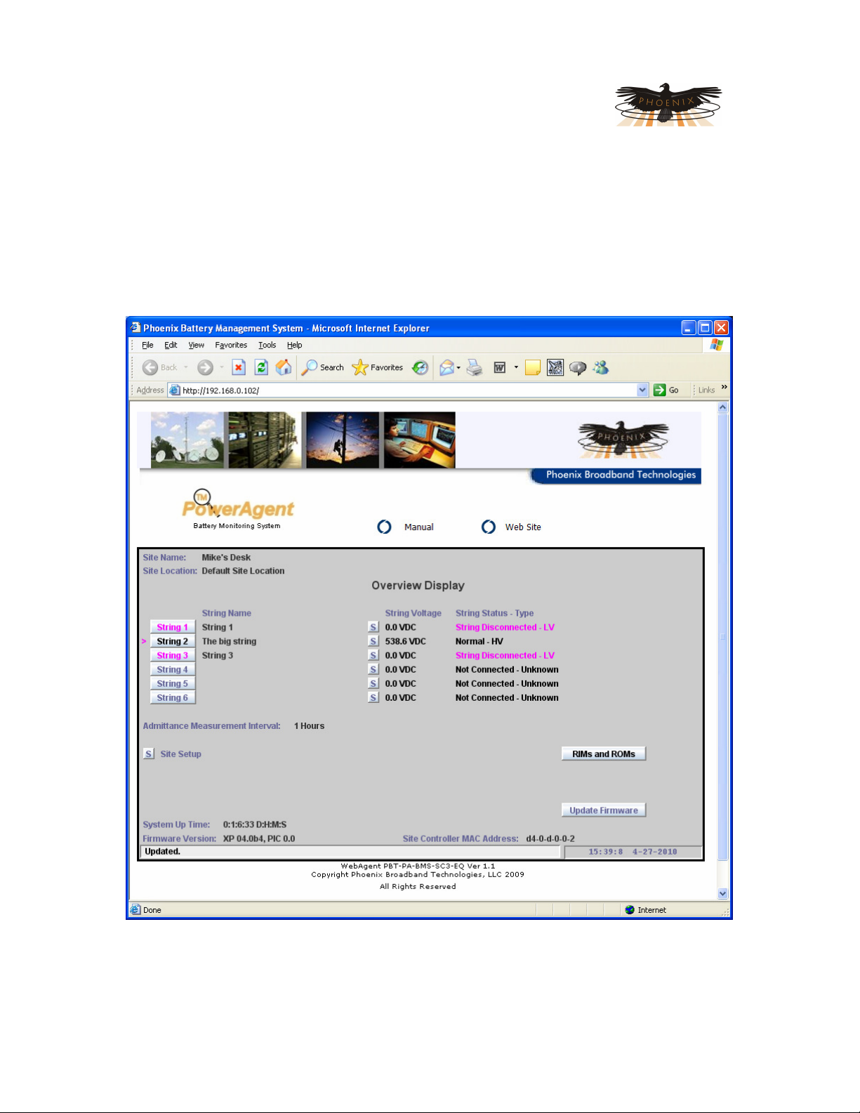
6.1 Overview Display .......................................................................................................... 32
6.2 Single String Display..................................................................................................... 33
6.3 Single Jar Display ......................................................................................................... 35
6.4 RIM and ROM Main Display ...................................................................................... 37
6.5 Provisioning................................................................................................................... 38
6.5.1 Provisioning Site Settings ..................................................................................................... 39
6.5.2 Provisioning String Settings ................................................................................................. 41
6.5.3 Provisioning Jar Settings ...................................................................................................... 43
6.5.4 Provisioning the Sensor Calibration ..................................................................................... 45
6.5.4.1 Calibrating using an Instrument........................................................................................ 45
6.5.4.2 Setting the Calibration ...................................................................................................... 46
6.5.4.3 Provisioning the Baseline ................................................................................................. 47
6.5.4.4 Baselining using the Present Measurement ...................................................................... 47
6.5.4.5 Baselining using Manufacturer’s Specifications............................................................... 47
6.5.4.6 Setting a Baseline ............................................................................................................. 47
6.5.5 Provisioning Analog Alarms ................................................................................................ 49
6.5.6 Provisioning Discrete Alarms............................................................................................... 50
6.5.7 Provisioning The ROM......................................................................................................... 51
7 SNMP......................................................................................................................... 52
7.1.1 MIBs ..................................................................................................................................... 53
7.1.2 Community Strings ............................................................................................................... 54
7.1.3 Traps ..................................................................................................................................... 54
7.1.4 MIB Browsers....................................................................................................................... 54
8 Updating Firmware ................................................................................................... 55
9 Summary of Port Usage ............................................................................................ 56
10 Resolving Common Problems................................................................................ 57
Phoenix Broadband Technologies, LLC 10/28/2010
Page 3 of 57
Page 4

PowerAgent TM SC3 Site Controller Document # 700-000014-01 Rev 2
Installation and Operation
1 Important Information
1.1 Revision History
Release Date Revision Description
Rev 1 04/27/2010 Draft for review, Firmware version 4.04, Web version 1.1
Rev 2 05/12/2010 On going revisions, Firmware version 4.10, Web version 1.3
1.2 Safety Notes
High currents and voltages may be present on the equipment terminals and on the
interior of the equipment. Make sure you understand and observe all appropriate
safety codes and regulations. Follow prudent electrical safety practices when
installing or servicing the equipment. Installation, maintenance and servicing of
the equipment should only be performed by qualified, trained and authorized
personnel.
Before installation, take measurements with a Volt Meter to ensure that no jar post in the
system has lethal AC or DC voltages relative to earth ground.
Except as explained in this manual, there are no user-serviceable parts inside the
PowerAgent Battery Monitoring System components. Opening the equipment could
expose you to dangerous voltages and void the product warranty. All product servicing
should be referred to factory-authorized personnel.
Use only interconnection cables supplied or authorized by Phoenix Broadband
Technologies. Use of user-made interconnection cable assemblies could result in
damage to equipment and potential safety hazards and voiding of equipment warranties.
Do not exceed the voltage specifications of the product.
Make sure the equipment is grounded properly.
The equipment should be protected from liquids, moisture, explosive, and corrosive
vapors.
Phoenix Broadband Technologies, LLC 10/28/2010
Page 4 of 57
Page 5

PowerAgent TM SC3 Site Controller Document # 700-000014-01 Rev 2
CAUTION!
NOTE:
Installation and Operation
1.3 Important Symbols
The following symbols are used in this document.
The use of CAUTION indicates safety information intended to prevent damage and/or injury
A NOTE to provide additional information to help complete a specific task or procedure
1.4 Definition of Terms
Admittance – The inverse of Impedance in units of Siemens. Admittance is a measure of how
easily a circuit or device will allow a current to flow. Resistance is a measure of the opposition of
a circuit to the flow of a DC current, while impedance takes in to account not only the resistance
but AC effects (known as reactance) as well. Likewise, admittance is not only a measure of the
ease with which a DC current can flow (conductance, the inverse of resistance), but also takes in
to account the AC effects of susceptance (the inverse of reactance).
Battery – A collection of jars connected in series. A battery is sometimes referred to as a Battery
String or String in this document.
Cell – A collection of plates connected to a single positive and single negative terminal immersed
in electrolyte in a single container. The cell may have multiple positive and negative connections
but they connect to a single set of plates. A lead acid cell produces approximately 2.1 volts.
Jar – A collection of one or more cells connected in series in a single housing. A 12 volt jar
contains 6 cells. A Jar is commonly and incorrectly referred to as a battery.
P-Bus – A Phoenix proprietary communications interface and protocol used to connect devices to
the Site Controller for the purpose of providing additional input, output, and measurement
capability.
Phoenix Broadband Technologies, LLC 10/28/2010
Page 5 of 57
Page 6

PowerAgent TM SC3 Site Controller Document # 700-000014-01 Rev 2
Installation and Operation
1.5 Contact Information
If you have any questions about the installation or use of the equipment described in this manual,
contact Phoenix Broadband Technologies (PBT) at (215) 997-6007 or
customerservice@phoenixbroadband.com.
When contacting Phoenix Broadband please have the following information available:
1. Site Controller Model Number and firmware version (from the Site Controller Web Page).
2. Battery Sensor Model Number, hardware version and firmware version. The version
numbers are shown on the Site Controller single Jar Web Page.
3. The Battery and String Voltage.
4. The battery model number.
5. UPS or DC power plant.
6. If a UPS the manufacturer and model number.
Phoenix Broadband Technologies, LLC 10/28/2010
Page 6 of 57
Page 7
PowerAgent TM SC3 Site Controller Document # 700-000014-01 Rev 2
Installation and Operation
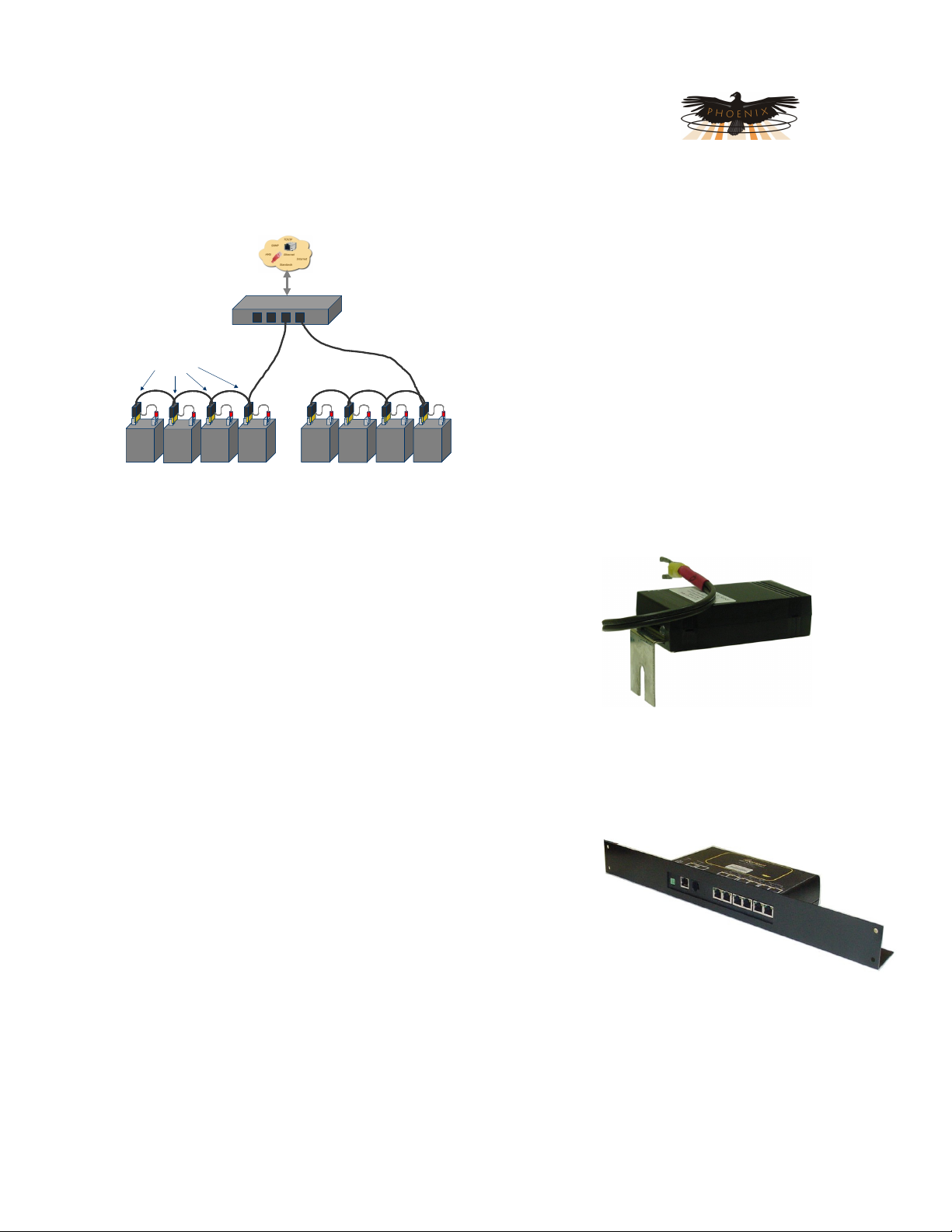
2 System Overview
Network
Conn ectivity
MasterA gent
Site
Contro ller
Up To 6
Batter y
Batte ryAgent
Sensor
Units
Batt ery String # 1 Batt ery String # 2
String s
RJ-11
“Dai sy Chain ”
area network. The Sensor modules are designed for use with 2 or 12 volt jars in DC power plants
and UPS power systems up to 600 volts DC and with several choices of mounting brackets for
different post configurations.
Each sensor in a PowerAgent
TM
Battery Management System
measures its associated cell or jar’s terminal voltage, post or
case temperature, and internal cell impedance (admittance).
Multiple sensors within a string of monitored jars are
interconnected in a “daisy-chain” utilizing CAT-5 cabling and RJ45 connectors. Each daisy-chain of sensors is connected via
another CAT-5 cable to one of the six string ports on the Site
Controller. Each site controller can manage up to six strings of
batteries with a maximum of 40 batteries in any string and a site
total of 240 batteries. The site controller has extensive user-definable set-up capabilities,
including labels for every monitored jar and alarm thresholds for voltage, temperature and
admittance on each individual jar.
The site controller has several user interface mechanisms built-in, including a configurable web
server that displays site, string, and individual jar
information, as well as an SNMP (Simple Network
Management Protocol) interface that allows any SNMP
compliant management software to collect data and
perform jar tests. Other features of the site controller
include a password protected Telnet port for remotely
configuring the unit, A DHCP (Dynamic Host
Configuration Protocol) client that automatically obtains
an IP (internet protocol) address from a DHCP server,
and TFTP (Trivial File Transfer Protocol) server for
uploading firmware changes remotely.
The Phoenix Broadband Technologies (PBT)
PowerAgent TM Battery Management System is
a comprehensive solution for remotely
monitoring the state of health for individual cells
or jars within the battery bank of a UPS or DC
power plant system.
The system consists of a series Sensor modules
which are electrically and mechanically affixed to
the terminal posts of the jars being monitored,
and a PowerAgent TM Site Controller unit which
collects readings from the individual sensors and
makes the information available for
management purposes via an Ethernet local
Phoenix Broadband Technologies, LLC 10/28/2010
Page 7 of 57
Page 8
PowerAgent TM SC3 Site Controller Document # 700-000014-01 Rev 2
Installation and Operation
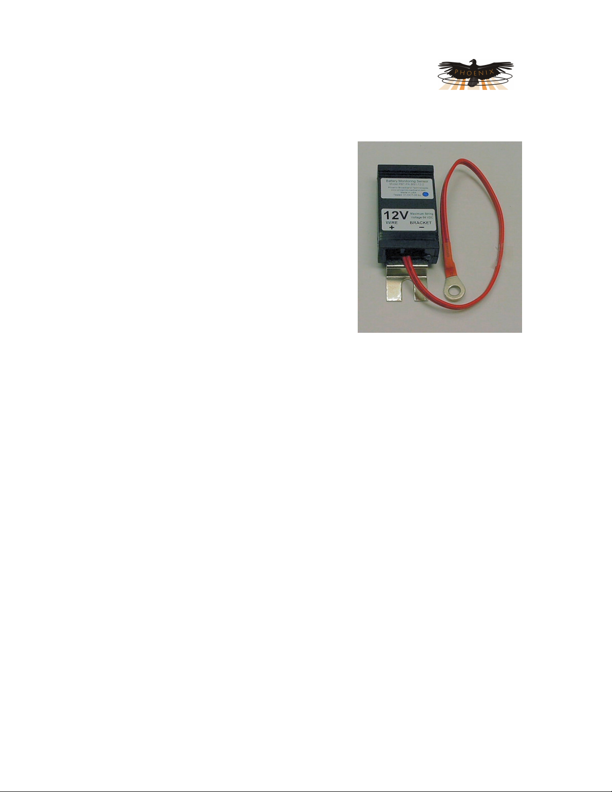
2.1 Sensor Description
Sensor modules are small, inexpensive units designed to
mount in close mechanical, electrical, and thermal
proximity to the monitored jar’s terminal posts. The sensor
takes a very small amount of “idling” power from the
monitored jar (typically less than 10ma). Internally, a
programmable microcontroller chip provides an optically
isolated communications interface for the site control unit.
Sensors are connected to the Site Controller using a
CAT5 cable daisy chain.
The sensor continuously monitors the voltage and
temperature of the jar. At user-defined intervals, the
microcontroller generates a digitally synthesized AC test
signal of approximately 0.5 to 6.0 amps (depending on
sensor type) which drives the jar’s terminals for testing
purposes. This test current causes a small AC voltage,
proportional to jar impedance, to be superimposed on the
jar’s DC terminal voltage. This AC voltage is separated from the DC terminal voltage and
amplified inside the sensor module. It is then fed to an analog-to-digital converter inside the
microcontroller chip. The microcontroller digitally samples the AC waveform and performs a DSP
(digital signal processing) algorithm that filters out noise and measures the amplitude of the AC
signal. These measurements and subsequent calculations determine the jar’s internal AC
impedance, which is the basis for Admittance measurements.
Mechanically, the sensor consists of a nickel-plated copper mounting bracket which fits on the
jar’s negative terminal post, a short wire terminated in terminal lug that connects to the jar’s
positive terminal post, and an electronics assembly that contains the test signal generation and
measurement circuitry. Sensors with two wires are also available.
The sensors with brackets have the advantage of being able to more accurately measure the
temperature of the electrolyte in the cell. The two wire sensors have the advantage of working
with a wide variety cell and jar mechanical configurations that could requires several different
bracket types. Refer to the Sensor Selector Guide later in this section for more details.
Each sensor is shipped with a 1 foot CAT5 cable to connect the sensor to the daisy chain. This
cable is the proper length for most applications. Longer cables are available from PBT.
2.1.1 “High Voltage” and “Low Voltage” Sensors
Sensors are typically used in DC power plant and UPS applications. DC power plant applications
commonly utilize two volt cells and twelve volt jars wired in series with total nominal string
voltages typically ranging from 24 to 48 VDC nominal. In many UPS systems, voltages can be
significantly higher (480 volts or more). Because of the specific requirements of high voltage
systems, Phoenix Broadband has developed two types of sensors to accommodate each
environment.
When working in environments where string voltages are greater than 64 VDC, always use the
High Voltage sensors. “High voltage” (HV) sensors are completely optically isolated from the
Phoenix Broadband Technologies, LLC 10/28/2010
Page 8 of 57
Page 9

PowerAgent TM SC3 Site Controller Document # 700-000014-01 Rev 2
PBT
-
PA
-
BS1
-12-2
Installation and Operation
controller and each other, with no string-level voltages present in the interconnecting CAT5
cables. This architecture was designed to ensure safety and prevent damage. For environments
where string voltages are 64 VDC and lower Low Voltage sensors are appropriate, however
either sensor (High or Low voltage) can be used low voltage strings.
CAUTION: Installing Low Voltage sensors on a high voltage string will damage the
sensors and may present a shock hazard.
Both sensor types will be auto-discovered by the controller. The Low Voltage sensor has the
advantage that its position in the string is automatically discovered. This means the sensors can
be connected in any order and the controller will automatically discover upon which cell or jar the
sensor was installed. High Voltage sensors have an address. The address and cell or jar
number must be recorded when the sensor is installed. These addresses are then entered into
the Site Controller Web page so that the ordering of the cells or jars will be correct.
High Voltage and Low Voltage sensor should not be mixed in the same string.
Each sensor has a bi-color red/green LED that indicates the operational state of the sensor and
its communications status with the site controller. Each sensor is also is internally fused so that
improper connection to the jar will not damage the jar, the jar cabling, or the sensor. Again, the
sensors are fully optically isolated from the site controller.
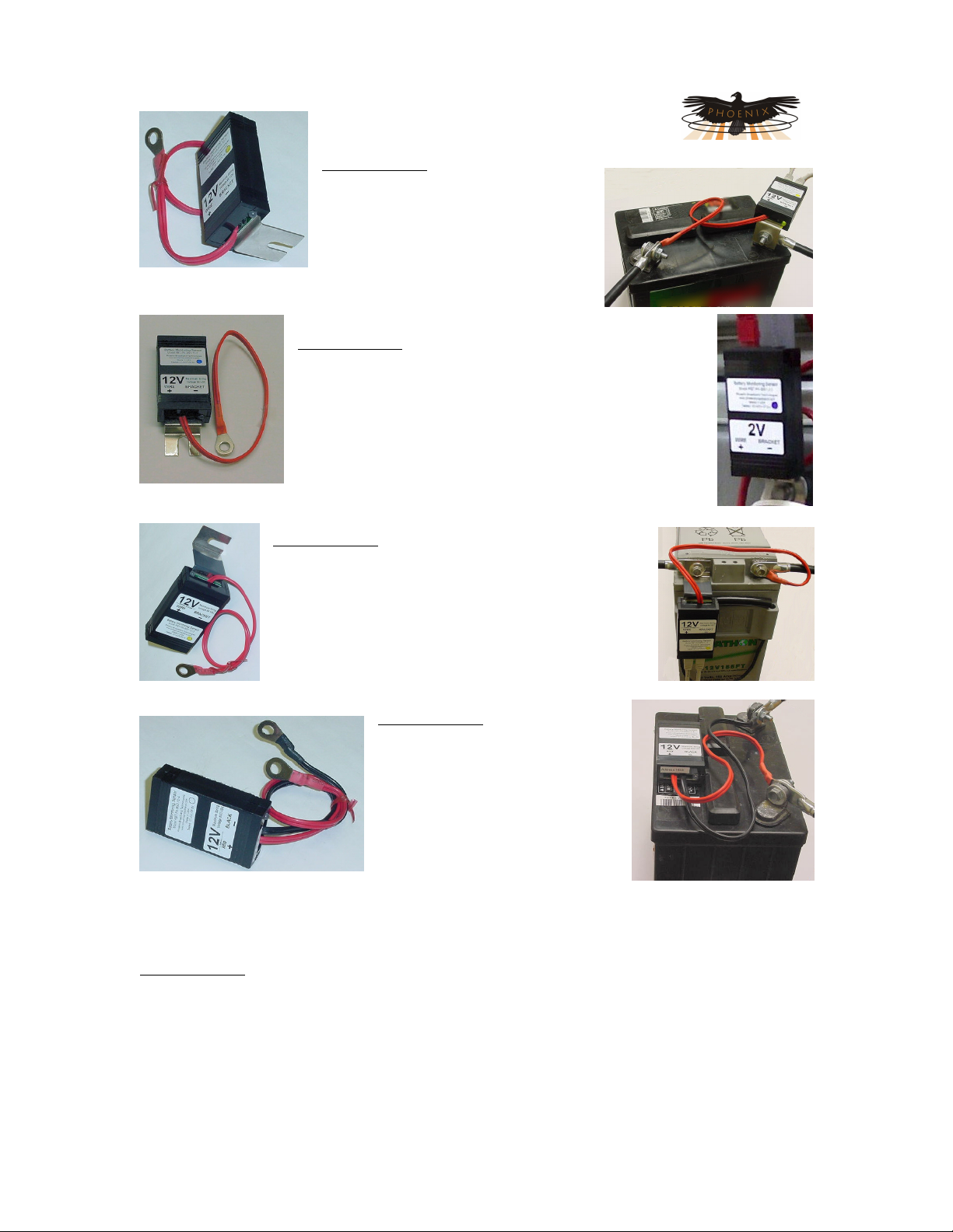
2.1.2 Sensor Selector Guide
Selecting a sensor requires first determining if a Low or High voltage sensor is required. Then a
jar voltage is selected, either 2 or 12 volts. Finally the bracket style is selected. The sensor
model number is constructed as shown below.
String Voltage
-BS1- Low Voltage (< 64 Volts)
-BS2- High Voltage (> 64 Volts)
-BS1B- Series B Low Voltage
-BS2B- Series B High Voltage
-BS3B- Series B Low Voltage, High Current
Jar Voltage
-2- 2 Volt Jars
-12- 12 Volt Jars
Series B sensors should be used for all new installations, they offer improved noise immunity and
an enhanced feature set including battery balancing. These sensors require a B series
SiteController.
When selecting a bracket be sure to consider the clearance above the jar. This is particularly
important when the jars are installed in a cabinet as is typical with most UPSs. Be sure there is
enough space for the CAT-5 cables to exit the sensor without kinking.
Bracket Type
-1 L Bracket
-2 Z Bracket
-3 Front Mount Bracket
-4 2 Wire Sensor
-5 12 mm Z Bracket
Phoenix Broadband Technologies, LLC 10/28/2010
Page 9 of 57
Page 10
PowerAgent TM SC3 Site Controller Document # 700-000014-01 Rev 2
Installation and Operation
Type 1 Bracket
This bracket commonly referred to as
the “L” bracket, is typically used on Jar
terminals where the sensor must stand
up from the jar. An example is the
vertical blade type terminal where the
bolt is parallel to the top of the Jar.
The maximum bolt size for the terminal and bracket is 5/16 inch.
Type 2 Bracket
This bracket, commonly referred to as the “Z” bracket, is
typically used jars that are connected together with straps.
It is also used when the jar cables are secured by bolts
that extend into the jar. The maximum bolt size for the
terminal and bracket is 5/16 inch.
Type 3 Bracket
This bracket, commonly referred to as the “Front
Mount” bracket, is used front terminal Jars. While
specifically designed for the Marathon, the bracket
will fit most front terminal Jars. This bracket was
designed for a M6 (6 mm) bolt.
Type 4 Bracket
This bracket is not a bracket at all
but a sensor with two wire
connections. This is the universal
sensor that will work with most
jars. The maximum bolt size for
the terminals is 5/16 inch. The
one disadvantage of this sensor is
that it does not directly measure
the jar post (electrolyte)
temperature like the bracketed sensors. When the sensor is mounted to the top of the jar, and
not in the direct cooling air flow, the sensor will read the approximate jar case temperature. The
sensor is equipped with a self adhesive industrial velcro strip for fastening the sensor to the jar.
Type 5 Bracket
This bracket is similar to the Type 2 bracket but is designed for a larger bolt. The maximum bolt
size for the terminal and bracket is ½ inch or M12 (12mm). Because of the higher torque
required for the larger bolt this bracket has a round hole rather than a slot. This prevents
distorting the bracket when tightening the bolt.
Contact PBT if none of these brackets fit your requirements.
Phoenix Broadband Technologies, LLC 10/28/2010
Page 10 of 57
Page 11
PowerAgent TM SC3 Site Controller Document # 700-000014-01 Rev 2
Installation and Operation
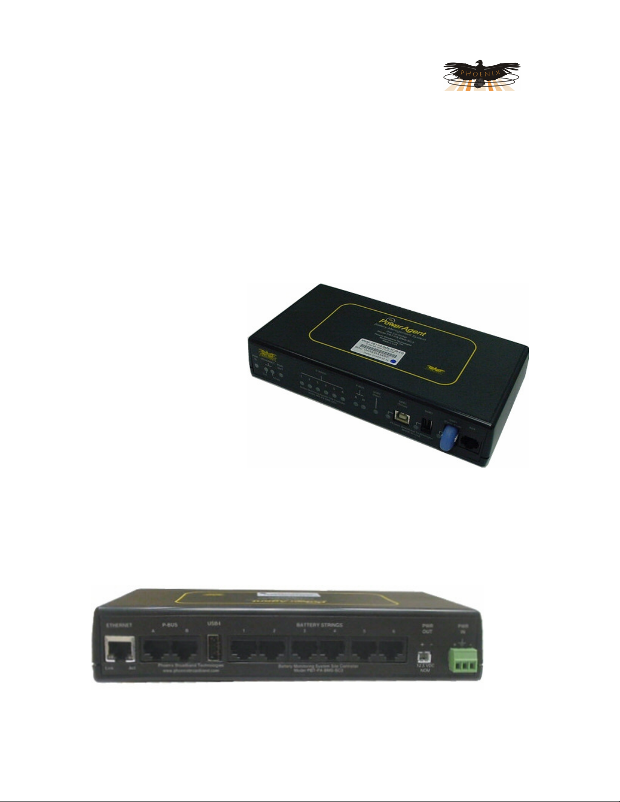
2.2 Site Controller Description
The Site Controller is a small, rack-mountable unit that monitors the sensor modules and makes
the data collected by them available via a local area network or the internet. The SC3 Site
Controller has 6 string ports for connection to strings of up to 40 jars each for a total capacity of
240 jars. Two P-Bus ports provide expansion capability for connection to current sensors, RIMs
and ROMs for additional input and output capability. A USB setup port allows direct connection
to a PC for configuration. A USB thumb drive provides storage of logged data and additional
USB ports provide expansion capability.
The SC3 Site Controller has most of the connections on the rear panel and indicators on the front
panel.
The SC3 Site Controller can be
powered directly from a battery
string voltage of 24-48VDC, or it
can be powered from an
optional small wall-mount
24VDC wall transformer. The
voltage range is 18 to 65 VDC
and power consumption is about
5 watts, with current draw
dependent on the input voltage.
Power is supplied to the unit via
a rear-panel screw-type terminal
block. The power supply input is
floating. The terminal block also
provides a chassis ground
connection.
A Front panel USB connection provides access to configure the Site Controller IP address and
other parameters during installation. Setup can also be performed over the network connection.
The site controller has six RJ-45 connectors on the rear panel for interfacing to up to six strings of
monitored jars. Each string has a front panel indicator. The LED lights when the string is being
polled. A green LED indicates everything is normal, a red LED indicates abnormal conditions
within that string.
An Rear Panel Ethernet connection provides a TCP/IP (internet protocol) interface to a local area
network or to the internet. A built-in web server is accessible via this interface, with no need for
any software other than a common PC web browser. More sophisticated monitoring and control
Phoenix Broadband Technologies, LLC 10/28/2010
Page 11 of 57
Page 12

PowerAgent TM SC3 Site Controller Document # 700-000014-01 Rev 2
Installation and Operation
of the site controller can be performed remotely using any SNMP-capable network management
software system. These systems are described in additional detail in the SNMP section of this
Manual.
Upon power-up, the site controller automatically begins a search sequence to determine which of
its string ports are attached to battery sensors and discovers each sensor module.
When a string of High Voltage sensors is discovered, the controller discovers the factoryprogrammed address of the sensor module as part of this discovery process. The HV sensor is
also assigned to one of the jars in the string, but the user can change these assignments after
installation is complete.
When a string of Low Voltage sensors is discovered the controller automatically discovers each
sensor and its correct position in the string (no factory programmed address is necessary with low
voltage sensors).
Once the “auto-discovery” process is finished, the site controller can individually address each
sensor, collect its readings, and display those reading in the hierarchical web page display.
Except for the final user assignment of High Voltage sensors to jars, this process is ‘plug & play’.
All sensor assignments and configuration information are saved in non-volatile memory, so the
system automatically reconfigures itself if power is lost or if the system is turned off for
maintenance.
The site controller can be mounted in any small, inconspicuous location that is available, or it can
be rack-mounted in a standard 19” (or 23” with adapter ears) equipment
rack by using the optional rack-mount bracket. One rack bracket can hold
one or two site control units. Rubber feet, screws for mounting the site
controller to the rack bracket, and extra sensor fuses are included with the
Site Controller.
2.3 Accessories
Various optional accessories are available to aid in the system installation.
2.3.1 Cable Kits
A Cable kits provides the cables necessary to connect a string of jars to the site controller. Each
string requires a Cable Kit. The Cable Kit contains the cables most commonly required to
connect the string of jars. Cable Kits are
Cable Kit Model Number Jars per string
PBT-PAC-BMS-04 4
PBT-PAC-BMS-12 12
PBT-PAC-BMS-20 20
PBT-PAC-BMS-24 24
PBT-PAC-BMS-30 30
PBT-PAC-BMS-40 40
NOTE: We strongly recommend that you order the appropriate Cable Kit for each string
and not make your own sensor cables. A single improperly made cable can destroy an
entire string of sensors.
Phoenix Broadband Technologies, LLC 10/28/2010
available for common string sizes. Contact PBT
for any special requirements. The Cable Kit
contains the cables most commonly required to
connect the string of jars.
Page 12 of 57
Page 13

PowerAgent TM SC3 Site Controller Document # 700-000014-01 Rev 2
Installation and Operation
2.3.2 Power Transformer
The Site Controller is normally powered from the Rectifier or UPS battery
charger (24 to 60 VDC). In cases where this power is not available a 24 VDC
wall mount transformer is required to power the Site Controller. This
transformer can be ordered from PBT as model number WT-3.
2.3.3 Rack Mount Bracket
A bracket that mounts up to
2 Site Controller in a 1U
space in a 19” rack is
available by ordering model
PBT-RK-1.
Phoenix Broadband Technologies, LLC 10/28/2010
Page 13 of 57
Page 14
PowerAgent TM SC3 Site Controller Document # 700-000014-01 Rev 2
Installation and Operation
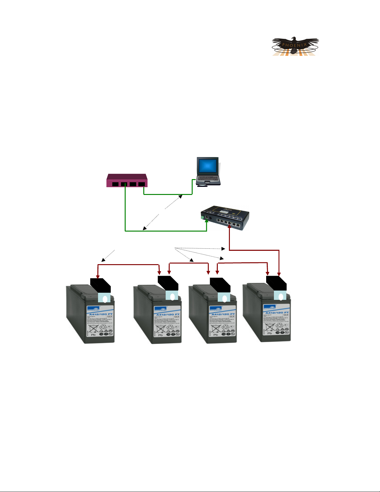
3 Initial Bench Evaluation
If the user has no previous experience with the PowerAgent TM Battery Management System, it is
recommended that a small local test and evaluation of the system components be set up prior to
field deployment of the equipment. This approach can save a significant amount of time before
connecting to a much larger network. It will allow you to verify proper operation of the site
controller’s web server; telnet configuration, and DHCP client without having to troubleshoot
larger network issues (firewalls, router, and connectivity etc.).
NNeettwwoorrkk RRoouutteerr
EEtthheerrnneett ccaabblleess
SSeennssoorr DDaaiissyy cchhaaiinn
CCAATT 55 ccaabblleess
BBMMSS ccoonnttrroolllleerr
The above diagram shows a low cost networking router (D-Link™, NetGear™, or other)
connected to a laptop/Desktop and the Site Controller. In this scenario the installation steps are
as follows:
1. Power up router
2. Power up laptop and connect laptop to router
3. Verify that the laptop has acquired an IP address from the router (view the router’s
configuration web page and write the address down)
4. Connect controller to router (via Ethernet connection)
5. Power up controller (upon power up, the controller will seek an IP address from the
router)
6. Connect sensors to the each other (via CAT 5 cables daisy chained from sensor to
sensor)
Phoenix Broadband Technologies, LLC 10/28/2010
Page 14 of 57
Page 15

PowerAgent TM SC3 Site Controller Document # 700-000014-01 Rev 2
Installation and Operation
7. Connect last sensor in the daisy chain to one of the six controller’s sensor input ports
8. View the router’s web page to determine which IP address has been given to the
controller (write it down)
9. Type the IP address of the controller into your laptop’s web browser and verify that the
web page displays properly. Verify that all sensors have been auto-discovered. Verify
that the parameter information displayed in the web page appears reasonable
10. Verify telnet connectivity by connecting to the controller via telnet (remember Phoenix
Broadband uses port 9999 for our telnet connection)
11. If you are using an SNMP manager, verify proper SNMP operation (gets, sets & traps)
This bench evaluation can also be performed using the free Lookout software described in the
SNMP section of this manual.
Phoenix Broadband Technologies, LLC 10/28/2010
Page 15 of 57
Page 16

PowerAgent TM SC3 Site Controller Document # 700-000014-01 Rev 2
Installation and Operation
4 Sensor Installation
Refer to the Battery Management System Manual (700-000006-02) for detailed information
before installing the battery sensors.
CAUTION! Lethal voltages may be present on the battery strings. If you are not sure of
what you are doing leave the installation to a certified technician. Read the sensor
installation instructions carefully.
CAUTION! Be sure to disconnect the Rectifier or Charger before installing the Sensors.
Failure to do so could result in sensor damage.
5 Site Controller Installation
NOTE: Before any sensor strings are connected to the Site Controller, it should be
mounted (either in a rack or shelf), connections should be made to the network (Ethernet
connection) and it should be powered up and checked out for network connectivity.
Select a location for the Site Controller. The location should be central to the strings being
monitored. It should be dry and free of corrosive or explosive vapors.
The maximum cable length between the SC3 Site Controller and the battery string varies with the
number of battery sensors on the string. With 40 sensors a maximum total cable length of 200
feet is recommended. This includes the sensor to sensor cables. With 24 sensors this increases
to 300 feet.
Mount the Site Controller in an equipment rack using the optional rack mount bracket, or place
the Site Controller on a shelf.
5.1 Powering
Connect a source of 18 to 65 volts DC to the rear panel power connector. This can be DC power
from a DC power plant or it can be 24 VDC from the optional WT-3 plug-in transformer. For UPS
installations the Site Controller should be powered from the WT-3 or other DC source. The WT-3
should be plugged into a outlet that is running on the UPS. Never power the Site Controller from
UPS batteries. The SC3 Site Controller can also be powered from low voltage AC. Consult PBT
for the voltage range limitations. There is a power input fuse inside the Site Controller. It is
extremely rare for this fuse to blow.
The power supply input is floating on the SC3 Site Controller. To ground the Site Controller
connect the center ground pin on the power connector to an earth ground.
Phoenix Broadband Technologies, LLC 10/28/2010
Page 16 of 57
Page 17

PowerAgent TM SC3 Site Controller Document # 700-000014-01 Rev 2
Installation and Operation
5.2 Network Connections
Connect the rear panel Ethernet connector to the network through a hub or switch. On a
managed switch, make sure that the switch port has been enabled.
Set the IP Address of the Site Controller as described in the following section.
Verify network communications by accessing the Web page and telnet setup menu over the
network.
5.3 Connecting Battery Sensors
Connect the cable from the battery sensor daisy-chain to an available “BATTERY STRINGS”
connector on the Site Controller rear panel.
NOTE: We strongly recommend that you order the appropriate Cable Kit for each string
and not make your own sensor cables. A single improperly made cable can destroy an
entire string of sensors.
The site controller will begin to auto-discover the sensors connected in each of the daisy-chains.
You will notice the String LEDs on the front panel flashing in sequence left to right. This indicates
that the controller is polling each string and looking for sensors on that string. Once a string has
been discovered it will be visible in the Web page.
5.4 Connecting RIMs and ROMs
RIMs and ROMS are connected to one of the P-BUS connectors on the rear of the Site Controller
using CAT-5 cables. Up to 200 feet of cable can be connected each of the two P-BUS ports. Up
to 4 RIMs and 4 ROMs can be connected to each P-Bus port, for a total of 8 RIMs and 8 ROMs.
Refer to the RIM and ROM installation manual for information on mounting and configuring the
RIM and ROM.
5.5 Connecting Current Sensors
Up to 6 Current Measurement Interfaces (CMI) can be connected to P-BUS port A. These 6 units
correspond to the 6 strings. Each CMI must be set to a unique addresses, from 1 to 6. The
Addresses correspond to the 6 strings. For example; current measurements made on CMI
address 2 are displayed with string 2.
Phoenix Broadband Technologies, LLC 10/28/2010
Page 17 of 57
Page 18

PowerAgent TM SC3 Site Controller Document # 700-000014-01 Rev 2
Installation and Operation
5.6 Setting the IP Address
In order to communicate over the network, the Site Controller must be assigned an IP address.
There are several ways the IP address can be assigned.
• You can pre-configure your DHCP server to assign a reserved IP address to the Site
Controller based on the Site Controller MAC Address. The MAC address is printed on
the Site Controller label. This method is commonly used for field installations.
• You can let your DHCP server assign an address and then interrogate the DHCP server
to determine what address was used. This technique works well in the lab environment
where the DHCP server may be in a router. This method is not very practical for field
installations since the IP address can change if the Site Controller resets or the DHCP
server decides there is a reason to change the address.
• You can program a static IP address in the Site Controller using a temporary connection
to a router with a built-in DHCP server and the Site Controller Telnet configuration port.
• You can program a static IP address in the Site Controller directly using the USB
interface and a PC as described in the next section.
• You can program a static IP address in the Site Controller using an Ethernet Crossover
cable and a PC as described in the next section.
Generally, static IP addresses are used so that the Network Manager can associate the IP
address with a physical location. Contact your network administrator or IT department to obtain a
static IP address, gateway address, and sub net mask that will work on your network.
The Site Controller is shipped from the factory configured to obtain an IP address automatically
from a DHCP server.
5.7 Configuring the Site Controller
The Site Controller can be configured over the network through a telnet connection or through a
USB connection directly from a PC. Support of telnet is a standard part of Windows so virtually
any PC can configure the Site Controller.
There are several ways of connecting your PC to the Site Controller to access the configuration
program.
Phoenix Broadband Technologies, LLC 10/28/2010
Page 18 of 57
Page 19

PowerAgent TM SC3 Site Controller Document # 700-000014-01 Rev 2
Installation and Operation
5.7.1 Direct USB Connection
This method can always be used, and is required when the Site Controller has been programmed
with an unknown static IP Address.
The Site Controller is equipped with a USB interface that allows a PC to be connected to the Site
Controller through a USB cable to access the configuration program. A PC with a USB Port, a
serial communications program such as HyperTerminal or Tera Term is required. The USB
cable is provided with the Site Controller.
NOTE: HyperTerminal which has been part of Microsoft Windows since the beginning, is
no longer included with Microsoft Vista or Windows 7. HyperTerminal can be downloaded
from the internet and added to these systems. There are many other terminal programs available
on the internet that will work. We recommend Tera Term which can be downloaded for free at
http://www.ayera.com/teraterm/. Be sure to comply with all licensing requirements.
A USB driver may be required for your PC to connect to the Site Controller. The driver may be
downloaded from www.PhoenixBroadband.com/Downloads/mchpcdc.inf
Before connecting the Site Controller to your PC, download this driver to you desktop. Apply
power to the Site Controller and connect the USB3 port on the Site Controller front panel to your
PC using the cable provided. A flashing red LED next to USB3 indicated the USB connection has
not been established. The USB installation should begin shortly. When the wizard asks for the
location of the driver, point to your desktop. The LED next to USB3 will light green when the
USB interface has initialized.
5.7.2 USB Port Selection
To connect to the Site Controller with your serial communications program you will need to
identify which COM port is being used for the USB
serial communications.
1) Open the PC’s “Control Panel” and click on
the “System” icon.
2) Select the “Hardware” tab and click the
“Device Manager” button.
3) Navigate down the tree of Devices and
expand the “Ports (COM & LPT)” item.
4) Find the item labeled “Site Controller Com
Port (
COM#
installed on is shown in the parenthesis (
5) To change the Port, right-click the Device and select “Properties”. Select the “Port
Settings” tab and click on the “Advanced” button. A new Port # may now be selected
and applied from the “Advanced Settings” Window.
When configuring your Serial Communications program use the COM port number
identified above. If you program only supports low number COM ports, change the port
number as described in step 5.
)”. The Com Port that was
COM7 in the example
).
Phoenix Broadband Technologies, LLC 10/28/2010
Page 19 of 57
Page 20

PowerAgent TM SC3 Site Controller Document # 700-000014-01 Rev 2
Installation and Operation
5.8 Accessing the Setup Menu
To access the Site Controller setup menu connect the Serial Communications program
to the Site Controller using the USB interface as described above. Confirm that the USB
connection has been established by looking for the green LED next to USB3. Open the
Serial Communications program, select the COM Port identified above, and set the date
rate to 9600, 8 data bits, one stop bit, no parity, and no flow control. When the program
is configured properly the USB3 LED should flash off when you type on the keyboard.
Hold down the x (lower case) for about 5 seconds. A message “-- Device Reset, hold ‘x’
key down until prompted. --“, will appear. Continue to hold the x key until the setup
menu appears and then follow the setup instructions below.
5.8.1 Ethernet Crossover Cable Method
This method can be used when the Site Controller IP address is set to a known static address.
Connect an Ethernet Crossover cable between the PC and the Site Controller. Set your PC IP
address to the Site Controller Address + or – 1. Follow the telnet setup instructions below.
5.8.2 Router Method
This method can be used when the Site Controller is set for DHCP operation (Factory Default).
Connect the Site Controller to a router that supports DHCP. This is generally done with a router
designed for home use but this process can also be used with most commercial routers and
DHCP servers if the proper access is available. The DHCP server will automatically assign an IP
address to the Site Controller which will enable network access to the Site Controller for
configuration. Your router should have a built in Web Server or some other method of
determining what IP address was assigned to the Site Controller(refer to the router manual).
Once the IP Address is known the Site Controller can be configured through a telnet connection
as described below.
Phoenix Broadband Technologies, LLC 10/28/2010
Page 20 of 57
Page 21

PowerAgent TM SC3 Site Controller Document # 700-000014-01 Rev 2
Installation and Operation
5.8.3 Running the Site Controller Telnet Setup
To open a telnet connection to the Site
Controller select “Run” from the Windows Start
menu. Enter “telnet” followed by a space,
then, the IP address of the Site Controller
followed by a space, and then the port number
“9999” followed by “Enter”. If the Site
Controller is on, line and the telnet password
is enabled the following screen will be
displayed. If the telnet password is not
enabled, skip to the next step. Note that the
screens in this document may be slightly
different than your Site Controller screens. The Site Controller will not ask for the password when
using the direct USB connection.
Enter the password. You only
have a few seconds before
the session times out. If the
password is accepted the
following screen will be
displayed, if the password is
not accepted the telnet session will be terminated.
Type “Enter”, to display the
setup menu shown in the
next section. For security
purposes, if “Enter” is not
typed in a few seconds the
telnet session will be
terminated by the Site
Controller.
Phoenix Broadband Technologies, LLC 10/28/2010
Page 21 of 57
Page 22

PowerAgent TM SC3 Site Controller Document # 700-000014-01 Rev 2
Installation and Operation
5.9 Site Controller Setup Menu
No matter what method of access was used the Setup Menu will then be displayed as shown
below. These screen shots were made with a telnet client but they will look the same in a serial
program.
The top two thirds of the screen
displays the present
configuration. The menu at the
bottom of the screen displays
the setup menu.
Closing the telnet window
will terminate the telnet
session and reset the Site
Controller. To avoid resetting
the Site Controller exit by
pressing “8” followed by “Enter”.
Phoenix Broadband Technologies, LLC 10/28/2010
Page 22 of 57
Page 23

PowerAgent TM SC3 Site Controller Document # 700-000014-01 Rev 2
Installation and Operation
5.9.1 Setting the IP Address (0)
Various options can be controlled by setting the IP address. For static IP address operation the
IP address should be set to the address assigned by the IT department or other authority. Other
IP address options are as follows.
If the IP address is set to 0.0.0.0 DHCP is enabled. (Factory Default)
If the IP address is set to 0.0.1.0 DHCP is enabled and AutoIP is disabled.
If the IP address is set to 0.0.9.0 DHCP is enabled, DHCP option 81 is disabled, and AutoIP is
disabled.
To change the IP Address select option 0 from the setup menu by typing a 0 followed by “Enter”.
The following screen will appear.
The current value of the first
octet of the IP address will be
shown in parenthesis. This
indicates that the first octet of
the IP address is 0. To
change the octet, type the
new number followed by
“Enter”. To move on without
making any changes, just type
”Enter”.
In this example the first octet
of the IP address was
changed to 192.
Continue entering each octet
of the IP address until all 4
octets have been entered. To
skip any entry without making
any changes type “Enter”
without typing any numbers.
Next the Site Controller will ask if you would like to set the Gateway IP Address. The Gateway
address is required for the Site Controller to initiate communications with other devices on the
network; such as the time or
email servers. This address
is obtained automatically
when running with DHCP,
however when a static IP
address is assigned to the
Site Controller the Gateway
Address must be set
manually. The Gateway Address is normally set to the IP Address of the first router encountered
by outbound network traffic. To change the address, type a “Y” and enter the IP address as
described above. To skip the address, type an “N”.
Phoenix Broadband Technologies, LLC 10/28/2010
Page 23 of 57
Page 24

PowerAgent TM SC3 Site Controller Document # 700-000014-01 Rev 2
Installation and Operation
The Site Controller will now ask for the Network Mask. To change the mask, enter the number of
bits required for the local host.
Example; For 255.255.255.0
enter 8, for 255.255.252. 0
enter 10. Verify the Net
Mask was set correctly by
observing the displayed value
when the menu returns to the
screen. The table below shows the value to be entered for common Net Masks.
Next the Site Controller will ask if a telnet password is desired. A
four character password can be selected to secure telnet access to
the Agent. Use caution when selecting a password. If you forget the
password or enter it incorrectly the Site Controller must accessed
using the Programming Adapter to reset the password. To set the
password, enter a “Y” and then the password following the prompt.
To remove a password enter a “Y” and then an enter at the prompt.
Value
Net Mask
2 255.255.255.252
3 255.255.255.248
4 255.255.255.240
5 255.255.255.224
6 255.255.255.192
7 255.255.255.128
8 255.255.255.0
9 255.255.254.0
10 255.255.252.0
Finally the Site Controller will
ask if you would like to
change the DHCP device
name. We recommend that you do not change this setting. Type enter to return to the menu.
To save your changes, type ” 9” from the menu. The changes will be saved in nonvolatile
memory, the telnet session will be terminated, and the Site Controller will reset.
5.9.2 Web Passwords (1)
To change the Passwords used for Web Page access type “1” followed by “Enter”. The user
Password will be displayed. To change the user password type the new password followed by
“Enter”. To keep the present
password type “Enter”.
Passwords can be 20
characters long and are case
sensitive.
Change the administrator
password in a similar fashion.
The password changes will
immediately be saved to
nonvolatile memory and become effective. Type “8” followed by “Enter” to close the telnet
session without resetting the Site Controller.
Phoenix Broadband Technologies, LLC 10/28/2010
Page 24 of 57
Page 25

PowerAgent TM SC3 Site Controller Document # 700-000014-01 Rev 2
Installation and Operation
5.9.3 SNMP Agent Configuration (3)
The SNMP Community Strings and Trap destinations are configured from the SNMP
Configuration.
The default community strings
are set to “public”. To change
the community string type “3”
followed by “Enter”. The
present read (Set) community
string will be displayed in
parenthesis as shown. To
change the community string,
type the new string followed
by “Enter”. To move to the
next item without changing
the community string just type
“Enter”. The write (Set)
community string is next and is handled the same way, followed by the Trap community string.
NOTE: Community strings are case sensitive.
Up to 3 Trap destinations can be configured. The IP addresses of the Trap destinations are set
similar to the IP address
described above. To disable
sending Traps to any of the
three IP address enter zeros
for the IP address.
The Site Controller includes a feature that will reset the device if a SNMP message is not
received for approximately 2
hours. This safety feature is
primarily used when the
device is located in a remote
unmanned location. If the
SNMP firmware hangs this
may recover the device
without a visit to the remote location. The default setting is disabled. To enable the reset type a
“Y”, to disable the feature type an “N” or “Enter”.
The menu will be redisplayed at the end of the SNMP Configuration. Select “9” to save the
changes and close the telnet session.
5.9.4 HMS Defaults (4)
To restore the factory default settings for all SNMP objects, type a “4” followed by “Enter”. The
SNMP, Email, NTP, Gateway, Net Mask, and IP Address will not be changed. The telnet session
will be closed and the Site Controller will be reset.
Phoenix Broadband Technologies, LLC 10/28/2010
Page 25 of 57
Page 26

PowerAgent TM SC3 Site Controller Document # 700-000014-01 Rev 2
Installation and Operation
5.9.5 Email Setup (5)
The Email system will mail alarm messages to up to 3 email addresses.
To setup the Email system, select 5 from the setup main menu. Enter the outgoing Email server
name. If there is no server name the email system is disabled. If a server name was previously
entered it will be shown. To
change the server name just
type the new name followed
by “Enter”. To keep the
server name shown, type
“Enter”. To remove the
server name (or the contents of any other text field) type any character, then “Backspace”
followed by “Enter”. The IP address of the mail server can be entered in place of the server
name if the server is unnamed.
If your server requires a user name and password enter the user name followed by “Enter”. If the
user name is left blank the Site Controller will not
send the user name and password to the mail
server. To keep the present name type”Enter”.
Now enter the server password followed by “Enter”.
Up to 3 Email address may now be entered.
The address are changed the same as the
server name.
Next enter the From Address. This is the
address that will show up in the Email when it
is received.
NOTE: The From Address should generally be set to an address that is registered on the
SMTP server. Many servers use this to authenticate the outgoing Email.
Phoenix Broadband Technologies, LLC 10/28/2010
Page 26 of 57
Page 27

PowerAgent TM SC3 Site Controller Document # 700-000014-01 Rev 2
Installation and Operation
Finally set the Domain Name
Server (DNS) IP address. The
DNS allows the Email
application to obtain the IP
address of the specified server
so it can send the mail. There
are fields for a primary and
secondary DNS. The IP
Address are set as described in the IP Address section of this document. The default is a
commonly used DNS (4.2.2.2). Change this to your local DNS if you prefer. As long as the Site
Controller can see the internet the default DNS will work. If the DNS IP addresses are set to
zeros, the Email will be disabled.
To save your changes, type ” 9” from the menu. The changes will be saved in nonvolatile
memory, the telnet session will be terminated, and the Site Controller will reset.
Phoenix Broadband Technologies, LLC 10/28/2010
Page 27 of 57
Page 28

PowerAgent TM SC3 Site Controller Document # 700-000014-01 Rev 2
Installation and Operation
5.9.6 Time Server Configuration (6)
The Site Controller can set its internal clock from any internet time server that supports Network
Time Protocol (NTP). There are many such servers around the world. Many of these servers are
operated by government standards organizations. Most private networks also have time servers.
The Site Controller is shipped with the NTP configuration set to get the time from two different US
National Institute of Standards time servers. The IP addresses of these servers can be changed
in the NTP Configuration. If the time server addresses are not configured or the Site Controller is
unable to contact either time server the Site Controller will initialize the time to 00:00:00 1/1/2008.
If communications is not established with a time server the internal clock will run from this point.
The time provided by most time servers is Greenwich Mean Time (GMT). The Site Controller will
convert this to Local Time using a time offset that can be entered in the NTP Configuration.
To configure the NTP select
option 6 from the
Configuration Main Menu.
Enter the IP addresses as
described in the IP Address
section of this manual. There
are two Time Server addresses. The Site Controller will use the
Time Offset
from GMT
12 NZST 720
11 660
10 GST 600
9 JST 540
8 CCT 480
7 420
6 360
5.5 IST 330
5 300
4 240
3 BT 180
2 EET 120
1 CET 60
0 GMT 0
-1 WAT 65476
-2 AT 65416
-3 65356
-4 AST 65296
-5 EST 65236
-6 CST 65176
-7 MST 65116
-8 PST 65056
-9 YST 64996
-10 AHST 64936
-11 NT 64876
-12 IDLW 64816
Time
Zone
Time
Offset
primary server unless it fails to respond and then it will switch to
the secondary. It will not switch back unless the secondary
server fails to respond or the Site Controller is reset. To change a
default Time Server IP Address to undefined, enter zeros for the
IP address.
The Site Controller will reset itself if there is no communications
with either time server for approximately 2 hours. To disable the
reset function enter zero for all 4 octets of the primary time server
IP address. The Site Controller will use the secondary Time
Server to set the time if the second IP address valid.
The time read from the time server is GMT. There is an option in
the NTP Setup to enter a time offset to correct the time to read
local time. If the time offset is positive, east of the UK, simply
enter the offset in minutes. If the time offset is negative, west of
the UK, the offset must be entered in 2’s compliment form. To
compute the value subtract the time offset in minutes from 65536
and enter the result. For example the offset to Eastern Daylight
time is 4 hours. 65536 - 240 = 65296 Enter 65296 as the time
offset for Eastern Daylight time. The table to the left contains the
offset value for each major time zone.
To save the changes, type ”9” from the menu. The changes will
be saved in nonvolatile memory, the telnet session will be
terminated, and the Site Controller will reset.
Phoenix Broadband Technologies, LLC 10/28/2010
Page 28 of 57
Page 29

PowerAgent TM SC3 Site Controller Document # 700-000014-01 Rev 2
Installation and Operation
5.9.7 Restore Factory Defaults (7)
To restore the factory default settings type a 7. All SNMP, Email, NTP, and HMS values will be
set to the factory defaults. The IP Address will not be changed, however the Gateway and Net
Mask settings will be set to the factory default values.
NOTE: Be careful. Changing the Gateway and Net Mask settings could prevent
communications with the Site Controller, requiring a site visit.
5.9.8 Exit (8)
Type a “8” followed by an “Enter”, to exit the setup program, close the telnet window without
saving the changes to nonvolatile memory, and without resetting the Site Controller. Some
changes will take affect (SNMP) others will not (Email).
5.9.9 Save and Exit (9)
Type a “9” followed by an “Enter”, to save all changes to nonvolatile memory, close the telnet
window, exit the setup program, and reset the Site Controller so all changes take affect.
5.9.10 Erase All String and Jar Data (13)
Typing “13” followed by “Enter” will erase all of the String and Jar data from the Site Controller
nonvolatile memory and then reset the Site Controller. All user entered data for the strings and
jars including names and alarm setups will be lost. The other settings will not be changed.
5.9.11 Reset All Sensors (14)
Typing “14” followed by “Enter” will reset all the Sensors. The telnet session will remain open and
no settings will be changed. The reset will force all of the sensors to be rediscovered.
5.9.12 Erase String (15)
Typing “15” followed by “Enter” will erase a specified string. You will be prompted for the string
number. The telnet session will remain open and no settings will be changed.
5.9.13 Erase RIM/ROM Flash (16)
Typing “16” followed by “Enter” will erase the RIM and ROM database. All settings will be lost
and the devices will no longer appear in the Web page or SNMP MIBs unless they are
rediscovered. The telnet session will close and the Site Controller will reset.
Phoenix Broadband Technologies, LLC 10/28/2010
Page 29 of 57
Page 30

PowerAgent TM SC3 Site Controller Document # 700-000014-01 Rev 2
Installation and Operation
5.10 Web Server
The Site Controller contains a Web Server that provides a complete set of Web Pages to observe
and configure the Monitoring System from a Web Browser.
The Web Browser will load a Java applet from the Site Controller when the Web Page is opened.
The applet is used to support the communications between the Web Browser on your PC and the
Site Controller. For this to operate, the Java Runtime Environment (JRE) must be installed on
your PC. This is a common function of many Web Sites so it is likely that the Java Runtime
Environment is already loaded on your PC.
If you need to load the Java Runtime Environment go to the Sun Java Web Site at:
http://java.com/en/download/windows_automatic.jsp
and follow the directions to download and install the latest version of the JRE. This is a free
download.
The Site Controller web server has been tested to work with many versions of the Sun
Java Runtime Environment. Versions of the Java Runtime Environment older than 1.4.2
may not function properly. Most newer versions appear to work properly but occasionally a
version may have a bug that inhibits some feature. Contact PBT if you suspect an incompatibility.
To check which version you are using on your PC open a Microsoft Internet Explorer and select
Tools -> Internet Options -> Advanced. Scroll down to the line that displays Java (Sun). The
version number of the Java Runtime environment installed on your PC will be shown. If this line
is not present the Sun Java Runtime Environment is not installed on your PC.
5.10.1 Accessing the Web Server
To access the Site Controller Web page type: “http://192.168.0.5” from your web browser. This
IP Address is an example, substitute your Site Controller’s IP address in place of “192.168.0.5”.
5.10.2 Ports
The Site Controller Web server uses Ports 80 and 30704 to receive requests from the PC. The
ports on the PC are selected automatically. Port 80 is the normal HTTP port. Port 30704 is used
by the Java applet to get data from the Site Controller for the real time screen updates.
The transaction goes something like this; When the Web browser is opened the PC assigns an
outgoing port X and sends a request to port 80 on the Site Controller. The Site Controller replies
with a response to the PC sent to port X. The java applet opens a connection on PC port Y to
request the real time data and sends this request to Site Controller port 30704. The Site
Controller responds to PC port Y with the requested data.
Both ports X and Y are selected by the PC. These ports may be mapped to other ports by
routers in the communication path. This does not cause any problems since the Site Controller
always responds to the port specified in the request.
If the Web page draws but the applet is unable to connect to the Site Controller chances are good
that port 30704 is being blocked by a firewall or router. This could be on your PC or somewhere
in the network. Consult with your IT people to find the problem.
Phoenix Broadband Technologies, LLC 10/28/2010
Page 30 of 57
Page 31

PowerAgent TM SC3 Site Controller Document # 700-000014-01 Rev 2
Installation and Operation
6 Navigating the Web Pages
NOTE: The site controller web page uses a java applet, communicating on UDP port
30704, to deliver real time information. If you have trouble viewing the web page this port
may be blocked, contact your IT department.
The status of the batteries that are being monitored by a Site Controller can be viewed using any
network-connected PC that has a web browser.
Type the IP address of the site controller in the browser’s URL address space, for example
“192.168.0.102”. The
controller will serve
the intial web page
which lists all battery
strings discovered,
their total string
voltage and their
status. On the bottom
left hand corner of the
web page you will see
text which toggles
between “Updated”
and “Connected”.
This indicates normal
operation, however, if
you see the message
“Trying to Connect” or
“Unable To Connect”
you may have
problems with a
firewall or router
blocking UDP port
30704. Contact your
IT department for
assistance.
The time displayed at
the lower right of each
web page is the PC
time, not the Site Controller time.
Phoenix Broadband Technologies, LLC 10/28/2010
Page 31 of 57
Page 32

PowerAgent TM SC3 Site Controller Document # 700-000014-01 Rev 2
Installation and Operation
6.1 Overview Display
From the initial web page the user can select any available string and view details.
The button text on this page is color coded to indicate the String status. Normal status is
indicated by black, red indicates a major alarm, yellow indicates a minor alarm, green indicates
an admittance measurement is in process on the string, and magenta indicates a warning
condition.
When the Site Controller starts the previous string configuration is loaded from the database. This
configuration will be updated as new strings or jars are discovered. During the Site Controller
initialization a message “Site Controller Initializing” will appear. While this message is present the
Site Controller is checking for new sensors and collecting data (including admittance
measurements) for all sensors. Alarm checking and SNMP communications are disabled until
initialization is complete and the message disappears, to prevent alarming or reporting erroneous
readings.
Pressing the RIM/ROM button brings up RIM and ROM main page which is described later in this
document. This button is color coded with the RIM and ROM alarm status.
The Update Firmware button is used to load new firmware into various system components.
This capability is currently available for the float current sensor and is under development for
other system components. Consult PBT for the latest information on availability of this feature.
System Up Time is the time the Site Controller has been running since the last reset.
Phoenix Broadband Technologies, LLC 10/28/2010
Page 32 of 57
Page 33

PowerAgent TM SC3 Site Controller Document # 700-000014-01 Rev 2
Installation and Operation
6.2 Single String Display
The Single String Display lists all jars associated with a string. Each string can be given its own
name which is displayed near the top of the page.
This page will display up to 40 jars. For each jar present in the string the jar voltage and
admittance change is displayed. The admittance change field will indicate “undefined” until the
initial cell admittance has been set in the Jar Setup Display.
The button text on this
page is color coded to
indicate the jar status.
Black Normal
Green Measuring
Admittance
Blue Equalizing
Red Major Alarm
Yellow Minor Alarm
Magenta Warning
Buttons will change
from Cell, for a 2 volt
cell, to Jar for a multicell jar. Press a Jar or
Cell button to view the
detailed information on
the jar.
The Discharge Status
indicator displays the
present state to this
string either “Normal”
or Discharging”. The
discharge event is
detected by the Float
Current Sensor. A
count of the Discharge
Events and the duration of the Present (or Previous) Event and the Total discharge Time are
also displayed. The event counter and total time are stored in nonvolatile memory and can be
reset from SNMP or by deleting the string. Alarms may be provisioned for the Discharge Status
by pressing the associated A button.
All Conductance measurements and Equalization are automatically disabled on all strings when a
discharge event is detected on any string.
The String Status field displays the present string monitoring status which is a summary of the
sensor status as described below.
Phoenix Broadband Technologies, LLC 10/28/2010
Page 33 of 57
Page 34

PowerAgent TM SC3 Site Controller Document # 700-000014-01 Rev 2
Installation and Operation
String Status Description
Normal The status of all sensors on this string are Normal
Disabled The string is disable through SNMP
Shorted The Site Controller output is shorted somewhere in the sensor daisy chain
MissingSensors More sensors were expected
TooManySensors More sensors are present than the string can handle
SensorFault One or more sensors are not communicating
Alarms One or more sensors have alarms
Initializing The string is initializing
SensorDisabled One or more sensor is disable through SNMP
StringDisconnected Nothing is connected to the Site Controller string port
NoSensorCom Something is connected to the port, but no sensors are communicating
The String Voltage reading displays the total string voltage measured by the sensors. For a Low
Voltage string this voltage is measured directly by the sensor on the most negative jar. For a
High Voltage string this voltage is the sum of the individual jar voltages. Alarms may be
provisioned for this voltage by pressing the associated A button.
The Cell Voltage Delta reading displays the difference between the highest and lowest jar
voltage. Too much variation in jar voltages could be an indication that there are problems with
some jars. Alarms may be provisioned for this voltage by pressing the associated A button.
The Sensor Com indicator will display “Normal” when the Site Controller is communicating with
all the battery sensors in the string and will display “Failed” when the Site Controller has lost
communications with one or more battery sensors. Alarms may be provisioned for this indicator
by pressing the associated A button.
The Current Sensor box will appear when there is a Current Monitoring Interface, with its
address set to the string number, connected to the Site Controller P-Bus A port. If the Float
Current Sensor is connected to the Interface the Float Current reading will be displayed. If the
sensor is not connected the reading will display “No Sensor”. Alarms may be provisioned for this
current by pressing the associated A button.
If the Discharge Current
Sensor is connected to the
Interface the Discharge
Current reading will be
displayed. If the sensor is
not connected the reading
will display “No Sensor”.
Alarms may be provisioned
for this current by pressing the associated A button.
If the Float Current Sensor is connected to the Interface the Ripple Current reading will be
displayed. If the sensor is not connected the reading will display “No Sensor”. Ripple current
readings are made automatically once per hour or on demand by pressing the “Measure Ripple
Current” button. Alarms may be provisioned for this current by pressing the associated A button.
The Com Status indicator will display “Normal” when the Site Controller is communicating with all
the Current Monitoring Interface and will display “Failed” when the Site Controller has lost
communications with the Current Monitoring Interface. Alarms may be provisioned for this
indicator by pressing the associated A button.
Refer to the String Setup Display for other Current Sensor Interface setup options.
Phoenix Broadband Technologies, LLC 10/28/2010
Page 34 of 57
Page 35

PowerAgent TM SC3 Site Controller Document # 700-000014-01 Rev 2
Installation and Operation
The String Current field in the lower right hand corner displays the string charge or discharge
current in amperes. This field is for use with a current sensor that is in development.
Pressing the Previous String or Next String buttons will move to the previous or next string on
this Site Controller. Pressing the Return to Overview Display button brings up the Overview
Display.
6.3 Single Jar Display
This web page displays the measurements and control for a single Jar. Alarming parameters are
color coded with red for major alarms and yellow for minor alarms.
A user definable Jar (or Cell) Name is displayed for each jar. Some operators use this field to
identify the manufacturer and model number of the jar, or the installation date. The name may be
modified by pressing the associated S button.
The Jar (or Cell) Voltage measured by the battery sensor is displayed. Measurements are
made and report each time the sensor is polled. Alarms may be provisioned for this current by
pressing the associated A button.
The Jar (or Cell) Temperature measured by the battery sensor is displayed. Measurements are
made and report each time the sensor is polled. Alarms may be provisioned for this current by
pressing the associated A button.
For multi-cell jars the Jar Admittance and Cell Admittance are displayed. For single cell jars
only the Cell Admittance is displayed. Battery sensors actually measure the Jar admittance,
which for single cell jars is the same as the cell admittance. The multi-cell Cell Admittance is
calculated from the Jar Admittance. Measurements are made at intervals specified in the Site
Setup Display. The time of the most recent measurement is also displayed.
Perhaps the most useful parameter is the Cell Admittance Change. This is the difference
between the present Cell Admittance and the user specified Initial Cell Admittance expressed
as a percentage. The cell admittance change provides an indication of how the jar has changed
over time. The date and time of the admittance measurement and the initial admittance setting
add a time perspective to the change. Alarms may be provisioned for the change by pressing the
associated A button.
Phoenix Broadband Technologies, LLC 10/28/2010
Page 35 of 57
Page 36

PowerAgent TM SC3 Site Controller Document # 700-000014-01 Rev 2
Installation and Operation
If the battery sensor is
equipped with the
electrolyte level
detection option the
Electrolyte Level will
be displayed as either
“Normal” or “Low”. If
the sensor is not
equipped with this
option the Electrolyte
Level will not be
displayed.
For High Voltage
sensors only the
Sensor Address is
shown for sensor
identification.
The Sensor Status
provides an indication
of what is happening
at the sensor. The
table below lists the
possible values of the
Sensor Status.
Sensor Status Description
Normal This sensor is operating normally
Fault There is no communications with this sensor
Measuring This sensor is making an admittance measurement
SensorDisabled This sensor was disabled through SNMP
StringDisabled This string was disabled through SNMP
Missing This sensor was expected based on the string voltage, but is not present
MeasurementFailed The last admittance measurement failed
Admittance measurements are normally made at a rate set by the Admittance Measurement
Interval set in the Site Setup Display. Pressing the Measure Now button will initiate an
admittance measurement on this sensor the next time it is polled. The measurement may take a
minute to start depending on what the Site Controller is doing at the time. When the
measurement starts the Sensor Status will indicate “Measuring”. The status will return to normal
when the measurement is complete.
Pressing the Flash LED button commands the battery sensor to flash its LED alternating
between Red and Green. The Sensor LED Control indicator displays the state of the LED either
“Normal” or “Flash Green/Red”. Additional LED states can be set by the SNMP Manager. The
flashing LED can help onsite personnel locate a jar in a large deployment. Depending on what
the Site Controller is doing it may take a minute for the LED to start or stop flashing when the
button is pressed.
Phoenix Broadband Technologies, LLC 10/28/2010
Page 36 of 57
Page 37

PowerAgent TM SC3 Site Controller Document # 700-000014-01 Rev 2
Installation and Operation
The Sensor Firmware Version and Sensor Hardware Version are also shown on this page.
These are needed when contacting PBT for support.
Pressing the Previous Jar or Next Jar buttons will move to the previous or next jar on this string.
Pressing the Return to String Display button brings up the Single String Display.
6.4 RIM and ROM Main Display
Pressing the RIM/ROM button in the Overview Display brings up the RemoteAgents Display.
This screen has a button for every RIM or ROM discovered by the Site Controller. When the Site
Controller is reset the previous population of RIMs and ROMs is loaded form the database.
Additional RIM and
ROMs are added as
they are discovered
by the Site Controller.
Pressing ant RIM or
Rom button will bring
up the RIM or ROM
screen.
The operation of the
RIMs is described in
the Remote Input
Module Installation
and Operation Manual
(700-000012-00).
The operation of the
ROM is described in
the Remote Output
Module Installation
and Operation Manual
(700- TBD – 00). The
provisioning section of
this manual describes
how to configure the
ROM contact closure
outputs to operate on
specific Site Controller
alarms.
Phoenix Broadband Technologies, LLC 10/28/2010
Page 37 of 57
Page 38

PowerAgent TM SC3 Site Controller Document # 700-000014-01 Rev 2
Installation and Operation
6.5 Provisioning
The process of setting up all the thresholds, labels, and other software-configured settings is
called “Provisioning”. Provisioning can be accomplished remotely either via an SNMP-compliant
application-specific software package, or via the site-controller’s built-in web interface. While,
provisioning via SNMP is complex without specialized software and is beyond the scope of this
document, these devices have been designed to work with a variety of software packages
Provisioning via the site-controller’s built-in web page is comprehensive and easy. The user can
specify custom labels for the site controller name, the site location, the name of each string, and
the name or type of each jar. In addition, the user can set alarm thresholds for every monitored
parameter, including individual alarm thresholds for each jar. Other user-generated parameters
include the interval at which batteries will be tested and an initial “reference level’ for
measurements and
alarm generation.
User-defined settings
via the web page are
password protected
so that only
authorized personnel
can change these
settings. There are
two levels of
password. The
default user password
is “user”. The default
administrative
password is “admin”.
Passwords are case
sensitive and can be
up to 19 characters in
length. The
passwords can be
changed from the
Telnet configuration
port described later in
this document.
Once a valid
password has been
entered the selected
page will be displayed. The password will timeout in there is no activity for 10 minutes or if the
Web Browser is closed.
In each of the web pages, any display field that has user-definable alarm settings associated with
it will display a button with an “A” inside it next to the field. Fields with other settings will
display a button with S. Clicking on the button will display a web page with the settings.
Phoenix Broadband Technologies, LLC 10/28/2010
Page 38 of 57
Page 39

PowerAgent TM SC3 Site Controller Document # 700-000014-01 Rev 2
Installation and Operation
6.5.1 Provisioning Site Settings
The configuration button for the site settings is located at the bottom left of the Overview Display.
Clicking this button will cause the Site Setup Display to be displayed. If the password was not
previously entered the password will be requested.
To change the Site
Name or Site
Location move the
cursor to the field and
type the new name or
location. The change
will be saved when
the cursor is moved to
a new field or a new
Web page is selected.
To change the
Admittance
Measurement
Interval for this Site
Controller, enter the
desired interval, in
hours.
The Conductance
Meter Notes field
provides a location to
note the type and
serial number of the
meter used to make
the reference
measurements. This
is useful since there is
substantial variation in the measurements made by different model meters.
If the administrator password was entered additional buttons will appear. These buttons are for
expert users only and are not required for normal operation.
Reset All Sensors will reset the battery sensors on all of the strings. The database is
unaffected. The sensors will be rediscovered on the next cycle.
Reset Local Port Controller will reset the microcontroller that is responsible for the local port
and the real time clock.
Reset Logging Controller will reset the microcontroller that is responsible for the thumb drive
and USB ports 2 and 4.
Flash the Modem Power will switch the power output off for a second and then back on again.
The Test Button is used for factory testing.
Phoenix Broadband Technologies, LLC 10/28/2010
Page 39 of 57
Page 40

PowerAgent TM SC3 Site Controller Document # 700-000014-01 Rev 2
Installation and Operation
Set the Site Controller Time will set the real time clock in the Site Controller to the PC time. This
is intended to be used to set the real time clock in Site Controllers that do not have access to a
time server. The time is set by sending GMT from the PC to the Site Controller and applying the
time offset programmed in the Site Controller. This may not result in the Site Controller time
being the same as the PC time, allowing the time to be set in Site Controllers that are not in the
same time zone as the PC. If the Site Controller is able to access a time server the time sent
from the PC will be overwritten when the time update occurs at approximately 10 minutes past
the hour.
Phoenix Broadband Technologies, LLC 10/28/2010
Page 40 of 57
Page 41

PowerAgent TM SC3 Site Controller Document # 700-000014-01 Rev 2
Installation and Operation
6.5.2 Provisioning String Settings
In the Overview Display there is an S button corresponding to each battery string. Pressing this
button will display the following page:
To change the String
Name enter a new
name and press one
of the buttons to apply
the name to this
string or to all the
strings.
Checking the
Equalize Enable box
will enable
equalization on this
string.
When the Site
Controller discovers
the sensors the jars
are numbered with jar
one being the most
negative. If jar one
should be the most
positive jar push the
String Polarity
Change button. A
warning message will
appear. Either accept
the change or cancel.
If a Current Measurement Interface is present for this string the Current Sensor Setup box will
appear. The polarity of either the Float Current Sensor or the Discharge Current Sensor can be
reversed in case they were installed incorrectly. Pressing the Zero the Float Current button will
zero the current sensor the same as pressing the button on the Current Sensor Interface.
Pressing the Undo Zero Set button removes the zero calibration. The P-Bus Voltage is
measured at the Current Sensor Interface. The voltage should be above 4.5 VDC. Lower
voltages indicate that the P-Bus may be overloaded.
If the Administrative Password was entered three additional buttons will appear. If the Measure
Admittance on All Jars button is pressed, an admittance measurement will be made on all jars
in this string.
If the Reset This String button is pressed a reset command will be sent to all sensors on this
string. This will force the Site Controller to reinitialize the sensors.
If the Delete This String button is pressed the string will be deleted from the Site Controller. All
user settings for this string will be lost. If there are sensors connected to this string port on the
Site Controller they will be reset and rediscovered.
Phoenix Broadband Technologies, LLC 10/28/2010
Page 41 of 57
Page 42

PowerAgent TM SC3 Site Controller Document # 700-000014-01 Rev 2
Installation and Operation
NOTE: If a string is Deleted all user setting for the sensors on the string will be lost. This
includes Names, Addresses, Alarm Settings, and Calibration Settings.
Pressing the Return to Overview Display button will return to the Site Overview page.
Phoenix Broadband Technologies, LLC 10/28/2010
Page 42 of 57
Page 43

PowerAgent TM SC3 Site Controller Document # 700-000014-01 Rev 2
Installation and Operation
6.5.3 Provisioning Jar Settings
Pressing the S button in the Single Jar Display will produce the Jar Setup Display shown below.
NOTE: For High Voltage sensors reorder the jars as described below before entering any
other jar specific information.
To change the Jar Name enter a new name and press one of the buttons to apply the name to
this jar or to all the
jars on this string.
The Cell Admittance
Change alarm
requires the
specification of an
Initial Cell
Admittance. This
can be done in one of
two ways.
To use the present
Cell Admittance
reading as the Initial
Cell Admittance
press one of the
buttons in the Copy
Cell Admittance to
Initial Cell
Admittance group.
Pressing the This Jar
Only button will copy
the Cell Admittance
to the Initial Cell
Admittance for this
jar. Pressing the
Entire String button
will copy the Cell
Admittance to the
Initial Cell Admittance for each jar in the string.
To use a specified value for the Initial Cell Admittance enter the value in the field in the Set
Initial Cell Admittance group, then press on of the buttons. Pressing the Set This Jar Only
button will copy the value entered to the Initial Cell Admittance for this jar. Pressing the Set
Entire String button will copy the value entered to the Initial Cell Admittance for each jar in the
string.
NOTE: Low Voltage sensors are automatically discovered in string order so the following
process is not required. The Change Sensor Address field will not appear on the screen
for Low Voltage sensors.
Each High Voltage sensors has a factory programmed address. These addresses are recorded
during the discovery process that occurs when the Site Controller is powered on. The sensors
are discovered in a random order and assigned sequentially to the jars. This results in the
Phoenix Broadband Technologies, LLC 10/28/2010
Page 43 of 57
Page 44

PowerAgent TM SC3 Site Controller Document # 700-000014-01 Rev 2
Installation and Operation
random ordering of the jars shown in the Web page. To correct this problem start with jar 1 and
change the address of the sensor to the addresses recorded during installation. To change the
sensor address associated with this jar, enter the desired address in the Change Sensor
Address field. Push the Tab key to record the change. The change will be stored in nonvolatile
memory so the next time the string is initialized the jars will still be in the correct order.
When all addresses have been changed reset the String or cycle the Site Controller power to
reinitialize the sensors with the correct jar numbers. This should be done before entering any jar
specific information such as alarm limits, initial admittance, or admittance calibration.
Because there is a limit of 40 sensors per string, when replacing a sensor it may be necessary to
delete the old sensor to make room for the new sensor. To remove a sensor from the database,
press the Delete This Jar button. The jar will be erased from nonvolatile memory and all user
settings for the Jar will be lost. The delete button can also be used to remove any extra sensors
that during reconfiguration of strings of less than 40 sensors.
Phoenix Broadband Technologies, LLC 10/28/2010
Page 44 of 57
Page 45

PowerAgent TM SC3 Site Controller Document # 700-000014-01 Rev 2
Installation and Operation
6.5.4 Provisioning the Sensor Calibration
Instruments used to measure conductance or admittance can exhibit substantial variation
between various manufacturers and models of instruments. This variation is due to the different
techniques used to make the measurements and the different measurements actually made.
Some instruments measure DC resistance, others measure AC impedance at various
frequencies, still others measure the resistive component of the complex impedance at various
frequencies. These factors combine to produce variations of as much as 30% between
instruments.
In addition to these variations there is also significant variation due to the placement of the
instrument probes on the jar terminals. This is particularly important on high admittance batteries.
The admittance measurement made by the sensor without any calibration is accurate within 5%,
however this measurement may not agree with a specific instrument because of the factors
mentioned above.
6.5.4.1 Calibrating using an Instrument
The calibration process allows the monitoring sensor to be calibrated after installation using a
one-time measurement from a precision portable measuring instrument. Once a monitoring
sensor or transponder is installed on the equipment being monitored, reference measurements
from the precision instrument are entered into the monitoring system, and any errors between the
instrument and the sensor are subtracted before the result is displayed or reported. With
calibration, an inexpensive monitoring system gains all the advantages of stability, repeatability,
real-time-continuous data collection, and trend analysis, while retaining a measurement accuracy
that is comparable to the expensive portable instrument.
When monitoring a high capacity jar with an impedance/admittance monitoring system, the
sensor is required to measure jar equivalent resistances in the order of 100 micro ohms. The
resistance of the point of contact between the sensor and the jar strap or lug is typically in the
order of 35-75 micro ohms. In high capacity batteries this ‘spurious’ contact resistance can
produce errors of 20% or more. In the PBT Battery Monitoring System, the calibration process
essentially subtracts the spurious contact resistance from the total measured resistance, leaving
a stable, reproducible, and accurate measurement of true jar admittance that can be analyzed
and trended to allow pre-emptive maintenance. There are three software mechanisms that are
used to calibrate the admittance measurement:
Sensor Factory Calibration
The Site Control Unit recognizes the type of sensor that is used to monitor a high-capacity jar.
Whenever it receives a measurement from this type of sensor, it subtracts a small fixed
resistance (typically about 35 micro-ohms) from the reading before converting it to admittance
and displaying it.
String-Level On-Site Calibration
The installer can enter a user-defined constant into the Site Controller which will cause all the
batteries in a given string to be corrected, in addition to the built-in factory correction.
Individual Jar Calibration
The installer can enter an instrument measured admittance into the Site Controller which will
cause an individual jar to be corrected, in addition to the string-level constant and the built-in
factory correction.
Phoenix Broadband Technologies, LLC 10/28/2010
Page 45 of 57
Page 46

PowerAgent TM SC3 Site Controller Document # 700-000014-01 Rev 2
Installation and Operation
6.5.4.2 Setting the Calibration
Pressing the “S” button next to the Initial Cell Admittance label in the Single Jar Display screen
causes the Jar Setup Display screen to appear as shown below. This screen allows users to
make jar specific changes as described above.
The first step in the calibration process is to make and record admittance measurements for each
jar from a known good instrument such as the “Midtronics Ultra™”. If there is a significant
difference between
the sensor readings
and the readings
made with the known
good instrument, then
the instrument reading
can be entered in the
Set Instrument
Measured Cell
Admittance field.
Example: If the
sensor reading
indicates an
admittance of 3500
and the instrument
measured reading is
3600 the user can
type the instrument
measured value of
3600 into the Set
Instrument
Measured Cell
Admittance field.
When the instrument
measured reading is
entered, the actual
calculated Spurious
Resistance value
(represented in micro-ohms) will be displayed below the input field. The calibration can then
apply this value to a single jar by pushing the Calibrate This Jar Only button or to the entire
string by pushing the Copy Calibration to Entire String button.
To calibrate an Admittance reading it is necessary to make a new Admittance measurement.
When a Calibrate button is pressed a “Calibration Pending” message will appear in place of the
“Uncalibrated” message shown in the screen above. Within a few minutes the measurement will
be made and the “Calibration Complete, Reference Jar 5” message will appear. The reference
jar is the jar where the calibration value was entered. The calculated spurious resistance will also
be displayed. After calibration the “(uncal)” indicator in this screen and others will disappear. The
calibration information is saved in the Site Controller nonvolatile memory.
If the value is applied to the entire string the calculated Spurious Resistance value will be
displayed when viewing each jar. If, after applying a value to a string, a few individual batteries
still appear to be outside an acceptable range, you can go to the specific jar and enter a corrected
baseline reading for that single jar.
Phoenix Broadband Technologies, LLC 10/28/2010
Page 46 of 57
Page 47

PowerAgent TM SC3 Site Controller Document # 700-000014-01 Rev 2
Installation and Operation
6.5.4.3 Provisioning the Baseline
The baseline allows the admittance to be tracked based on an Initial Cell Admittance value.
Once this value is established admittance change alarms can be generated based on the percent
change from the initial value. The following sections describe two ways of establishing the
baseline.
6.5.4.4 Baselining using the Present Measurement
For new jars PBT recommends setting the baseline using the present admittance measurement
as a reference. With this approach the Admittance Change field will report the difference
between the present sensor reading and the reading when the jar was new. This is the simplest
and most accurate way to set the baseline. This method also works with jars that are not new,
however keep in mind that the reference was taken at an unknown point in the jar life span.
6.5.4.5 Baselining using Manufacturer’s Specifications
The Base can also be set using the jar manufacturer’s specified Admittance (or conductance) as
the basis for the measured admittance value. Sometimes the manufacturer specifies a DC
resistance or a short circuit current which allows the admittance to be calculated. Contact PBT if
you need help with this. With this approach the Admittance Change field will report the
difference between the present sensor reading and the manufacturer’s specification. Keep in
mind that the manufacturer’s specified Admittance (or Conductance) is based on measurements
made with an instrument and is subject to all of the variation factors listed above. In addition
most Manufactures specify a +/- 20 % tolerance on their specified value.
6.5.4.6 Setting a Baseline
Pressing the “S” button next to the Initial Cell Admittance label in the Single Jar Display screen
causes the Jar Setup
Display screen to
appear as shown
below.
To set a baseline
based on a
specification, enter the
baseline admittance
reading into the Set
Initial Cell
Admittance field.
Press either the Set
This Jar Only button
to set the baseline for
this jar, or Set Entire
String button to copy
this baseline to the
entire String. The
value will appear in
the Initial Cell
Admittance field and
the date and time will
be recorded for
reference. The Cell
Admittance Change
field in the Single Jar
Display will be
updated to show the
Phoenix Broadband Technologies, LLC 10/28/2010
Page 47 of 57
Page 48

PowerAgent TM SC3 Site Controller Document # 700-000014-01 Rev 2
Installation and Operation
difference between the Cell Admittance and the Initial Cell Admittance. To provision the
alarms press the A button next to the Cell Admittance Change field.
To set a baseline based on the present admittance reading press either the This Jar Only button
or the Entire String button in the Copy Cell Admittance to Initial Cell Admittance box. The
Present Admittance Cell Admittance value will be copied to the Initial Cell Admittance value and
the Cell Admittance Change field in the Single Jar Display will be updated to show the
difference between the Cell Admittance and the Initial Cell Admittance.
Phoenix Broadband Technologies, LLC 10/28/2010
Page 48 of 57
Page 49

PowerAgent TM SC3 Site Controller Document # 700-000014-01 Rev 2
Installation and Operation
6.5.5 Provisioning Analog Alarms
When the A button next to a measured parameter is pressed the Analog Alarm Setup screen
shown below will appear. There are 4 Alarm Limits that can be set independently and an Alarm
Enable check box for each alarm limit. When the enable box is checked, the alarm will occur
when the Present Value crosses the Alarm Limit. In the example below there is a Minor Alarm
because the Present Value is below the Minor Low Alarm Limit.
The Deadband
setting provides
hysteresis so the
alarm does not chatter
if the Present Value
is right at the alarm
limit. For High alarms
the alarm will occur
when the present
Value is greater than
the Alarm Limit. The
alarm will clear when
the Present Value is
less than the High
Alarm Limit minus
the Deadband.
Likewise for a Low
alarms, the alarm will
occur when the
present Value is less
than the Alarm Limit.
The alarm will clear
when the Present
Value is greater than
the Low Alarm Limit
plus the Deadband.
Minor and major
alarms operate independently so as the Present Value moves a minor alarm will become a major
alarm and vise versa.
Values in Yellow indicate a Minor alarm, Red indicates a Major alarm, and normal values are
block.
All alarm settings are nonvolatile and will be saved in the Site Controller database.
SNMP Traps and/or Emails may be sent whenever the alarm state changes and when the alarm
returns to the normal state. Refer to the Telnet Setup section of this manual for information on
setting the Trap destinations and Email addresses.
Phoenix Broadband Technologies, LLC 10/28/2010
Page 49 of 57
Page 50

PowerAgent TM SC3 Site Controller Document # 700-000014-01 Rev 2
Installation and Operation
6.5.6 Provisioning Discrete Alarms
Whenever the A button next to a discrete indicator is pressed the Discrete Alarm Setup display
will be shown. A description of the indicator and the present state will be displayed. The present
state will be color coded with the alarm status, red for Major, yellow for Minor, and black for no
alarm. Use the radio buttons to select either the Disabled, Minor or Major alarm.
All alarm settings are nonvolatile and will be saved in the Site Controller database.
SNMP Traps and/or
Emails may be sent
whenever the alarm
state changes and
when the alarm
returns to the normal
state. Refer to the
Telnet Setup section
of this manual for
information on setting
the Trap destinations
and Email addresses.
Phoenix Broadband Technologies, LLC 10/28/2010
Page 50 of 57
Page 51

PowerAgent TM SC3 Site Controller Document # 700-000014-01 Rev 2
Installation and Operation
6.5.7 Provisioning The ROM
The ROM can be configured to operate its outputs when specific Jar or String alarms occur. To
configure these alarms presses the Setup button for the desired output on the ROM display. The
screen shown below will appear. Assign an appropriate name to the output and the states as
shown in the example below. Output state 1 will be the normal state, and state 2 will be the alarm
state. When the alarm is detected the relay will switch to state 2. When the alarm clears the
relay will switch to state 1.
Select the desired
Output Control
Mode. For the Site
Controller to control
the output select any
of the three Site
Controller Modes. In
the example we have
selected Site
Controller – Major
Alarms. In this mode
only major alarms will
activate the output.
For normal operation
of the output select
SNMP or Web
Control.
Next select the
specific alarms that
will operate this
output. In the
example shown Jar
Voltage Alarms and
Jar Admittance
Alarms will trigger the
output.
Any number of ROM
outputs can be configured in this manor. Each ROM output can be programmed differently.
Phoenix Broadband Technologies, LLC 10/28/2010
Page 51 of 57
Page 52

PowerAgent TM SC3 Site Controller Document # 700-000014-01 Rev 2
Installation and Operation
7 SNMP
The Phoenix Broadband Battery Monitoring System provides an SNMP interface for third party
software management. The advantage of our approach is that it allows operators to choose the
software with which they wish to use as opposed to being locked into one software offering. Many
operators will
have their own
SNMP
management
software and will
want to integrate
the controller into
their existing
network
management
infrastructure.
SNMP is a well
known
communication
protocol which
provides a
standard interface
to different
management
software
platforms.
Phoenix Broadband offers an Enterprise Class software package designed specifically for
monitoring DC power plant and UPS back up batteries. The “Continuity” software platform is an
SNMP manager which provides many features users will require including a friendly web based
user interface, friendly controller provisioning (labels and alarms, etc.), reporting tools, flexible
notification plans and administration privileges.
Other commercially available SNMP managers such as NetCool or DataTrax could be used to
manage the Site Controller.
Phoenix Broadband also offers a simple software tool that can be used to manage the Site
Controllers. While not an Enterprise Class management system the Phoenix Lookout software
provides a convenient tool to manage a small group of systems. Lookout is available at
www.PhoenixBroadband.com/Lookout and is provided for free without a Warranty of any kind.
Refer to the Lookout manual included with the download for additional details.
Phoenix Broadband Technologies, LLC 10/28/2010
Page 52 of 57
Page 53

PowerAgent TM SC3 Site Controller Document # 700-000014-01 Rev 2
Installation and Operation
7.1.1 MIBs
All of the information presented on the Web pages and complete configuration capability is
available from SNMP.
SNMP uses the standard UDP ports 161 and 162. If the device does not respond to SNMP
Requests or does not appear to send Traps, confirm that these ports are not blocked.
The Site Controller uses a combination of standard and proprietary MIBs which can be found at
http://www.PhoenixBroadband.com/Downloads/MIBs/SiteController/SC3SiteControllerMIBS.zip.
These MIBS can also be obtained at no charge by contacting Phoenix Broadband.
The Site Controller requires the following standard SNMP MIBS to compile the MIBs below:
SNMP-FRAMEWORK-MIB
SNMP-NOTIFICATION-MIB
SNMP-TARGET-MIB
SNMPv2-SMI
SNMPv2-TC
ENTITY-MIB
The Site Controller supports the following SNMP MIBS:
SCTE 36 2002 (HMS028) Root MIB
SCTE 37 2002 (HMS072) Tree MIB
SCTE 38-1 (HMS026) Property MIB
SCTE 38-11 (HMS-114) Headend Ident MIB
SCTE 84-1 (HMS-111) HE Common MIB
pbtRootMIB Phoenix Root MIB
pbtBatteryAgentMIB Phoenix Battery Agent MIB
pbtRemoteAgentMIB Phoenix Remote Agent MIB
pbtEntityStatusMIB Phoenix Extensions to the Entity MIB
These MIBS should be compiled in the order listed.
The Battery Agent MIB contains tables of objects for each string and jar. These tables contain
name, status, and control objects as well as all of the voltage admittance and temperature
readings. All of the setable objects are stored in Site Controller nonvolatile memory.
The digital alarms are configured using the discreteAlarmEnable object in the
discretePropertyTable. There are two objects for each input. The first object (.1) is used to
enable alarms on the low state of the input. The second object (.2) is used to enable alarms on
the high state of the input. Each alarm can be set to one of 3 states Disabled(1), EnableMajor(2),
or EnableMinor(3). Major Alarms appear in red on the Web page, and Minor Alarms appear in
yellow.
The analog alarms are configured using the objects in the propertyTable. There are 4 objects to
set the thresholds for each of the alarm capable object. Each alarm limit can be individually
enabled or disabled.
Phoenix Broadband Technologies, LLC 10/28/2010
Page 53 of 57
Page 54

PowerAgent TM SC3 Site Controller Document # 700-000014-01 Rev 2
Installation and Operation
7.1.2 Community Strings
The community strings are configured from the Telnet interface described in the configuration
section of this document. The default community strings are set to “public”.
If the device does not respond to SNMP Requests or does not appear to send Traps, confirm that
the community strings are set properly in the SNMP Manager.
7.1.3 Traps
Whenever an alarm occurs SNMP Traps are sent to up to 3 trap receivers. The Trap
Destinations are configured from the telnet interface described earlier in this document. The
traps are defined in the heCommonMIB. Each traps includes a text field that describes the trap.
7.1.4 MIB Browsers
SNMP devices are normally managed by a software system containing a SNMP Manager. The
simplest method of evaluating SNMP operation is with a MIB Browser. A free evaluation version
of a MIB browser can be downloaded from http://www.ndt-inc.com/SNMP/MIBrowser.html or
http://www.mg-soft.com/download.html.
Phoenix Broadband Technologies, LLC 10/28/2010
Page 54 of 57
Page 55

PowerAgent TM SC3 Site Controller Document # 700-000014-01 Rev 2
Installation and Operation
8 Updating Firmware
The Site Controller Firmware can be updated remotely using TFTP. To perform this update you
will need a TFTP Client. A free TFTP Client can be downloaded from
http://tftpd32.jounin.net/tftpd32_download.html. Be sure to read and comply with the licensing
agreement. Other free TFTP clients are
available on the internet. This TFTP client is
used in the following example.
Before uploading firmware to a Site Controller
close any web browsers, or telnet clients that
are connected to the device.
Run the TFTP Client and the window to the left
will appear. Press the settings button and the
window below will appear. Ignore the Base
Directory setting and set all other options
exactly as shown. Then press OK.
Select the Tftp Client tab and enter the IP
Address of the device being updated in the
Host field. The Port field should be set to 69.
The Local File field should be set to the
Firmware or Web file to be downloaded.
Unlike previous Site Controllers, the files may
be loaded in any order. Set the Remote file
name as shown in the table below and the
Block Size to default.
Press the Put button to upload the file to the
Site Controller. A progress bar will appear as
the upload starts. The firmware upload
normally takes about 20 seconds. A Window
similar to the one below will appear when the
upload is complete.
Press OK and continue with the next file.
Phoenix Broadband Technologies, LLC 10/28/2010
Page 55 of 57
Page 56

PowerAgent TM SC3 Site Controller Document # 700-000014-01 Rev 2
Installation and Operation
The local and remote files names for the 7 Site Controller files are shown in the table below. The
Local file names may differ somewhat from the names shown depending on the version.
Local File Name Remote File Name
Firmware SC3_404.rom X2
Web files SC3_110_web1.cob WEB1
Web files SC3_110_web2.cob WEB2
Web files SC3_110_web3.cob WEB3
Web files SC3_110_web4.cob WEB4
Web files SC3_110_web5.cob WEB5
Web files SC3_110_web8.cob WEB8
TFTP uses UPD port 69. If you experience problems downloading firmware it is possible that port
69 is blocked by a firewall or router somewhere in you network. Consult with your IT department
to correct this problem.
9 Summary of Port Usage
The different features of this product use a variety of ports. The following table contains a
summary of the port utilization.
Port Protocol Usage
25 TCP SMTP – Sending email
69 UDP TFTP – Firmware updates
80 TCP HTTP – Web page
123 UDP NTP – Time server
161 UDP SNMP – Gets and Sets
162 UDP SNMP - Traps
9998 TCP Telnet – Debug port
9999 TCP Telnet – Setup
30704 UDP Java Applet – Web page real time data
It may be necessary to request the network administrator to open some of these ports, in the
firewall or router, for the associated feature to operate properly.
Phoenix Broadband Technologies, LLC 10/28/2010
Page 56 of 57
Page 57

PowerAgent TM SC3 Site Controller Document # 700-000014-01 Rev 2
Installation and Operation
10 Resolving Common Problems
1. Problem - The Site Controller resets approximately once an hour. Background – The Site
Controller updates its real time clock from a network time server approximately once per
hour. If the site Controller is unable to communicate with the time server it will reset in an
attempt to restore communications. Solution – First check if the Site Controller is getting
the time by looking at the time display above the telnet setup menu. If the time is correct
the Site Controller is communicating with the time server and the time server is not the
cause of the resetting. If the time is incorrect verify that the time server IP addresses are
correct and that port 123 is not being blocked by a firewall or router. Verify that the reset
is being caused by no time server communications by setting the IP address of the first
time server to zeros from the setup menu. This will disable the time server reset. Verify
that the time server IP addresses are correct.
2. Problem – The Web page opens but does not connect to the Site Controller. No realtime information is displayed. Solution – This problem occurs when UDP port 30704 is
blocked by a firewall or router in the network. The Java Applet running on the PC will
send message to Site Controller UDP port 30704 to obtain the data required to update
the Web pages. Consult with the IT department to determine where this port is being
blocked. To verify the Web server in the Site Controller is functioning; set the Site
Controller to a static IP address, and set your PC to this address +1. Connect the Site
Controller Ethernet connection directly to the PC Ethernet using a crossover cable. If the
Web page can be opened and updated when connected this way the Web Server is
working properly and the problem is in the network.
Phoenix Broadband Technologies, LLC 10/28/2010
Page 57 of 57
 Loading...