

Page 1
Powernode System Enclosures
Powernode System Enclosures
®
© 2002
Site Preparation and Installation
PN-3 Models
PN-4 Models
Effective: March, 2002
®
TM
Page 2

PN-3 & PN-4
www.alpha.com
Protecting The Power in Communications.
031-103-B0-003 Rev. C
2
© 2002
TM
Page 3

Powernode System Enclosures
PN-3, PN-4 Models
Site Preparation and Installation
031-103-B0-003 Rev. C — © 2002 Alpha Technologies
This manual covers the installation of the PN-3 and PN-4 Enclosure. Installation may involve connection to the electrical
utility lines and fuel vapor (Natural Gas or Propane). Always work with the local utilities when connecting the enclosure to
these utilities and observe all local and national laws which may be applicable for your area. Refer to Section 2, PreInstallation, for siteplanning and preparation.
Photographs contained in this manual are for illustrative purposes only. These photographs may not exactlymatch your
installation.
Review the drawings and illustrations contained in the manual before proceeding. If there are questions regarding the
safe installation and operation of this enclosure or the Powering System, please contact Alpha Technologies or your nearest
Alpha representative.
To contact Alpha Technologies:
For general product information and customer service
1-800-863-3930
(7:00 AM to 5:00 PM Pacific Time )
For complete technical support
1-800-863-3364
(7:00 AM to 5:00 PM Pacific Time, or 24/7 emergency support)
© 2002
TM
3
031-103-B0-003 Rev. C
Page 4

PN-3 & PN-4
Product Safety ....................................................................................................................................6
1. Introduction.................................................................................................................................... 9
1.1 Introduction ........................................................................................................................9
1.2 PN-3 and PN-4 Powernode Enclosure................................................................................10
2. Pre-Installation............................................................................................................................. 11
2.1 Site Preparation ................................................................................................................11
2.2 Concrete Pad Preparation..................................................................................................12
2.3 Enclosure Grounding.........................................................................................................13
3. Installation.................................................................................................................................... 15
3.1 T ransportation and Lifting.................................................................................................15
3.2 Enclosure Mounting Procedure..........................................................................................15
3.3 Utility Powering.................................................................................................................16
3.4 Coaxial Cable to Service Power Inserter (SPI) Installation.................................................22
3.5 Battery Installation ...........................................................................................................24
Table of Contents
Important Notes About Installation .................................................................................................... 7
Product Information, Customer Service or Technical Support ............................................................ 8
3.3.1 Connection Procedure for the BBX-100A-8POS Service Disconnect: ................................ 17
3.3.2 Connection Procedure for the BBX-70A Service Disconnect: ............................................ 18
3.3.3 Sample Input Power Panels..............................................................................................19
3.4.1 SPI to Ground Bar Connection Procedure ......................................................................... 22
3.4.2 Conduit Placement ........................................................................................................... 23
3.5.1 Battery Safety Notes.........................................................................................................24
3.5.2 Battery Identification ....................................................................................................... 25
3.5.3 Battery Terminal Connections........................................................................................... 25
3.5.4 Battery Terminal Assembly Procedure............................................................................... 26
3.5.5 Battery Installation Procedure .........................................................................................26
3.5.6 Battery Installation Layout ............................................................................................... 27
3.5.7 Battery Temperature Sensor .............................................................................................32
4. PN Series Options ........................................................................................................................ 33
4.1 Star Lock Security Bolt ......................................................................................................33
4.2 Battery Interface Unit (BIU)...............................................................................................34
4.3 Service Disconnects ..........................................................................................................34
4.4 Input Power Panel (IPP) ....................................................................................................35
4.5 Cooling Fan Kit.................................................................................................................36
4.6 Lightning Arrester (LA-P+)................................................................................................37
5. Alpha Part Numbers..................................................................................................................... 38
5.1 PN Series Options .............................................................................................................38
5.2 Pre-Cast Concrete Pads.....................................................................................................39
031-103-B0-003 Rev. C
4
© 2002
TM
Page 5

PN-3 & PN-4
List of Figures
Figure 1-1; Enclosure as it Arrives from Alpha ...................................................................................................................... 9
Figure 1-2; Packing Label Location ........................................................................................................................................ 9
Figure 1-3; PN-3 Specifications ........................................................................................................................................... 10
Figure 1-4; PN-4 Specifications ........................................................................................................................................... 10
Figure 2-1; Suggested Site Selection, PN-3 and PN-4 ......................................................................................................... 11
Figure 2-2; Single-Wide Concrete Pad for PN-3 and PN-4 ................................................................................................... 12
Figure 2-3; Suggested Grounding, PN-3 and PN-4 .............................................................................................................. 13
Figure 2-4; Alternate Grounding, PN-3 and PN-4 ................................................................................................................ 14
Figure 3-1; PN-3 Mounted to the Prepared Pad ................................................................................................................... 15
Figure 3-2; BBX-100A-8POS Service Disconnect.................................................................................................................. 17
Figure 3-3; BBX-70A Service Disconnect.............................................................................................................................. 18
Figure 3-4; Schematic: Primary Service BBX-100A-8POS with IPP-240-3 ........................................................................... 19
Figure 3-5; Schematic: Primary Service BBX-100A-8POS with IPP-120-3 ........................................................................... 19
Figure 3-6; Schematic: Secondary Service BBX-100A-8POS with IPP-120-2 ....................................................................... 20
Figure 3-7; Schematic: Secondary Service BBX-100A-8POS with IPP-240-2 ....................................................................... 20
Figure 3-8; Schematic: Secondary Service BBX-70A with IPP-120-1 ................................................................................... 21
Figure 3-9; Schematic: Primary Service BBX-70A with IPP-240-1 ....................................................................................... 21
Figure 3-10; Connector Fitting in Rear of Equipment Tray.................................................................................................... 22
Figure 3-11; Location of SPI in Equipment Tray .................................................................................................................... 22
Figure 3-12; SPI Ground Wire Connected to Enclosure Ground Bar ..................................................................................... 22
Figure 3-13; Conduit Location.............................................................................................................................................. 23
Figure 3-14; Coaxial Connectors .......................................................................................................................................... 23
Figure 3-15; Alpha Cell Battery Date Code .......................................................................................................................... 25
Figure 3-16; In-Line Fuse Link Mounting.............................................................................................................................. 25
Figure 3-17; Vertically Mounted Battery Post...................................................................................................................... 26
Figure 3-18; Battery Installation Arrangement.................................................................................................................... 27
Figure 3-19; Wiring Diagram for two 36V Battery Strings — PN3 Enclosure...................................................................... 28
Figure 3-20; Wiring Diagram for two 48V Battery Strings — PN3 Enclosure...................................................................... 29
Figure 3-21; Wiring Diagram for three 36V Battery Strings — PN4 Enclosure................................................................... 30
Figure 3-22; Wiring Diagram for three 48V Battery Strings — PN4 Enclosure................................................................... 31
Figure 3-23; Battery Temperature Sensor Mounting Location............................................................................................. 32
Figure 4-1; Security Bolt Location ........................................................................................................................................ 33
Figure 4-2; Black Clip in Place............................................................................................................................................. 33
Figure 4-3; Retaining Washer .............................................................................................................................................. 33
Figure 4-4; Security Key (Part Number 647-089-10)............................................................................................................ 33
Figure 4-5; Battery Interface Unit........................................................................................................................................ 34
Figure 4-6; BBX 70A (BBX-FI2)............................................................................................................................................ 34
Figure 4-7; BBX 100A (BBX-FI8).......................................................................................................................................... 34
Figure 4-8; MTS (Showing100A and 60A boxes) ................................................................................................................... 35
Figure 4-9; FBX-60A............................................................................................................................................................. 35
Figure 4-10; IPP for Three Power Supplies............................................................................................................................ 35
Figure 4-11; IPP for Two Power Supplies............................................................................................................................... 35
Figure 4-12; IPP for One Power Supply ................................................................................................................................. 35
Figure 4-13; Breaker Duplex Option (BDO) for One Power Supply......................................................................................... 35
Figure 4-14; Cooling Fan Panel............................................................................................................................................ 36
Figure 4-15; Panel is Installed in Top Rear of Enclosure...................................................................................................... 36
Figure 4-16; Cooling Fan Plugged into Power Supply and SPI.............................................................................................. 36
Figure 4-17; LA-P+ Installed in BDO ................................................................................................................................... 37
Figure 4-18; Location of LED on LA-P+. ............................................................................................................................... 37
Figure 5-1; Single-Wide Pad, for CE8/9 or PN 3/4 ............................................................................................................... 39
Figure 5-2; Double-Wide Pad, for CE8/9 or PN 3/4 .............................................................................................................. 40
Figure 5-3; Double-Wide Pad, for CE 3x2/9x2 and CE8/9 or PN 3/4 .................................................................................... 41
© 2002
TM
5
031-103-B0-003 Rev. C
Page 6
Product Safety
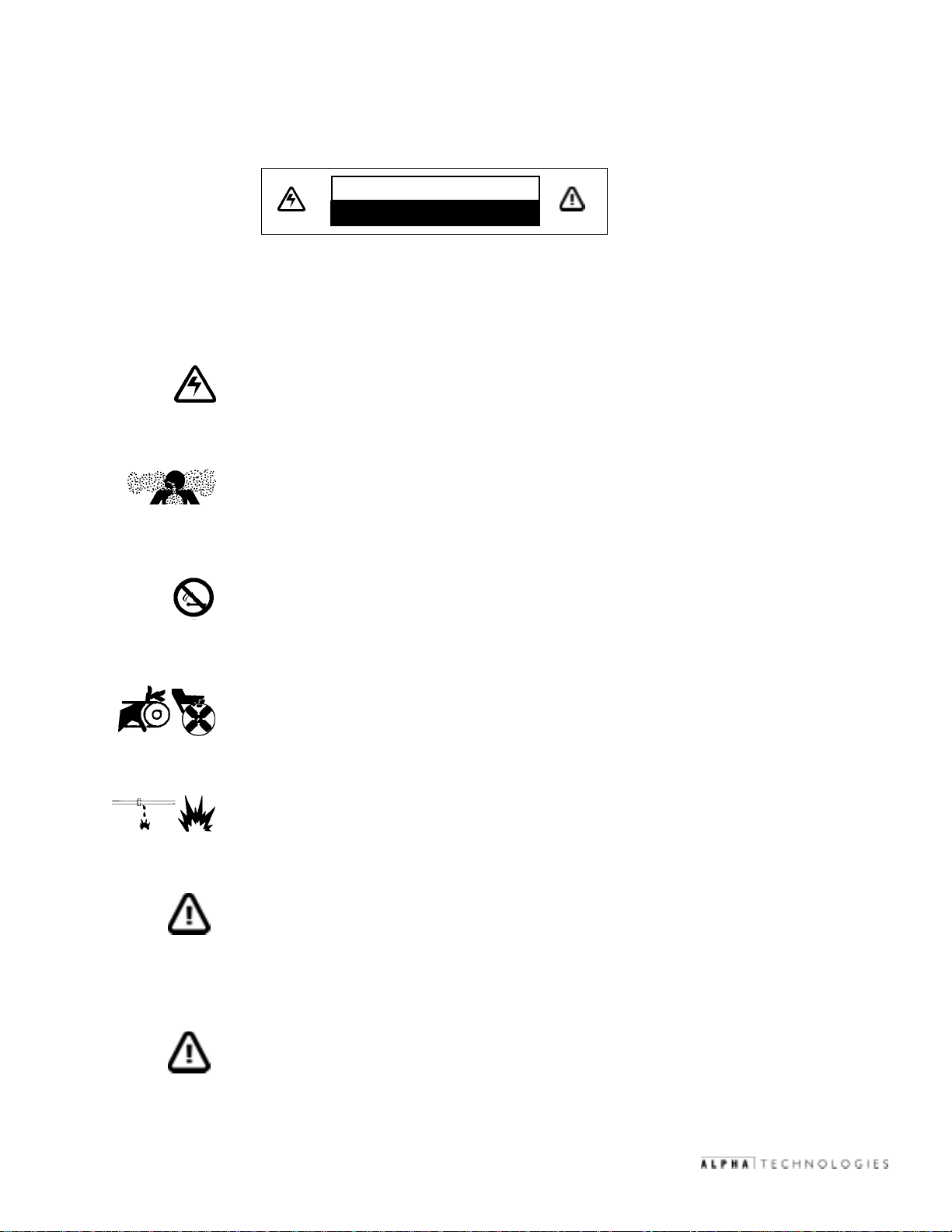
Important Safety Instructions Used Throughout this Manual
To reduce the risk of injury or death caused by electrical shock, explosion of fuel or moving parts; and to ensure the continued
safe operation of this product, the following symbols have been placed throughout this manual. Where these symbols
appear, use extra care and attention.
CAUTION
HAZARDOUS CONDITION
Dangerous Voltage
This symbol indicates a “dangerous voltage” may exist in this area of the product. Use caution whenever
working in the area to prevent electrical shock.
Inhalation Hazard - Don't Breathe Vapors
This symbol indicates an “inhalation hazard” may exist in this area of the product. Use caution
whenever working in the area to prevent possible inhalation of harmful (fuel or exhaust) vapors.
No Matches or Open Flames
This symbol indicates a “fire or explosive hazard” may exist in this area of the product. Use caution
whenever working in the area to prevent possible combustion of fuel vapors.
Mechanical or Moving Parts Hazard
This symbol indicates an “mechanical or moving parts hazard” may exist in this area of the product.
Use caution whenever working in the area to prevent possible injury to the operator or service personnel.
Leak Hazard
This symbol indicates a “leak hazard” may exist in this area of the product. Use caution whenever
working in this area to prevent and correct any leaks detected.
Attention
This symbol indicates important installation, operation or maintenance instructions. Always follow
these instructions closely.
031-103-B0-003 Rev. C
Save these instructions for future reference.
NOTE: Alpha Technologies’ products are subject to change through continual improvement
processes. Therefore, specifications and/or design layouts may vary slightly from
descriptions included in this manual. Updates to the manual will be issued when
changes affect form, fit or function.
6
© 2002
TM
Page 7

Product Safety
Important Notes About Installation
• The system must be installed only by qualified service personnel.
• Always consult local codes for mounting pad requirements.
• Consult local utility codes for additional cabinet grounding and utility requirements.
• Consult the local gas company for correct meter type and riser location.
• Whenever possible, it is best that the enclosure be installed above flood zones .
• Precast Mounting Pads may either be purchased from Alpha or poured in place. The pad must be
capable of holding 1,000 lbs (minimum). Rebar may be placed in a crosshatch pattern for pad
reinforcement, as needed.
• If the pad is to be located in an area with a deep frost line or unstable soil, concrete pylon footings (4"
diameter X 4' deep, or 1' deeper than the regional frost line) can be placed below the concrete pad, in
front of and below the (4) mounting features.
• The top of the pad must be above grade to reduce the buildup of debris around the base of the cabinet.
• Adequate space must be allowed for Cable TV input/output conduit; plant grounding electrode
conductor(s); RF cable entrance via (1) 4", (2) 3" or (3) 2 1/2" rigid conduit sweep(s) with 2' bend radius
(minimum); and fiber optic cable entrance (refer to fiber manufacturer's specification for minimum
bend radius requirements).
• Prior to pouring concrete, any wire running through the pad must have a thermal expansion jacket (i.e.,
PVC) to prevent cracking of the concrete during lightning strikes.
• Alpha Technologies is not responsible for broken welds or other damage to the cabinet caused by
improper installation.
• A 25+ year vapor barrier must be used between the concrete pad and the base of the enclosure to further
inhibit the ingress of moisture. Alpha Technologies is not responsible for water damage or moisture
damage resulting from improper installation.
• Concrete filled, 6" diameter steel posts (or equivalent) can be placed at the corners of the pad to reduce
exposure to accidental traffic damage.
• All dimensions are given in inches.
• For further information regarding this installation, contact Alpha Technologies or your nearest Alpha
representative.
© 2002
TM
7
031-103-B0-003 Rev. C
Page 8

Contacting Alpha Technologies
Product Information, Customer Service or Technical Support
For general product information and customer service 7:00 AM to 5:00 PM
Pacific Time, call:
1-800-863-3930
To obtain complete technical support 7:00 AM to 5:00 PM Pacific Time, or for
after-hours emergency support, call:
1-800-863-3364
(7 days per week, 24 hours a day)
Product Returns
Returns for Repair
In the event of a need for repair, Alpha products may be returned by either method listed below:
Download the necessary forms directly from Alpha's Web site, under "Support":
www.alpha.com/support/
OR
Call (800) 322-5742 for assistance.
Returns for Credit
Credit return requests must be initiated with a phone call. Call: (800) 322-5742.
031-103-B0-003 Rev. C
8
© 2002
TM
Page 9
1.1 Introduction
To ensure operator safety:
• Enclosures must be installed only by qualified personnel and in accordance with all applicable electrical
codes.
• Use eye protection whenever working with batteries.
• Use only sealed, lead-acid type batteries (gelled-electrolyte or equivalent, 65 Ah min.)
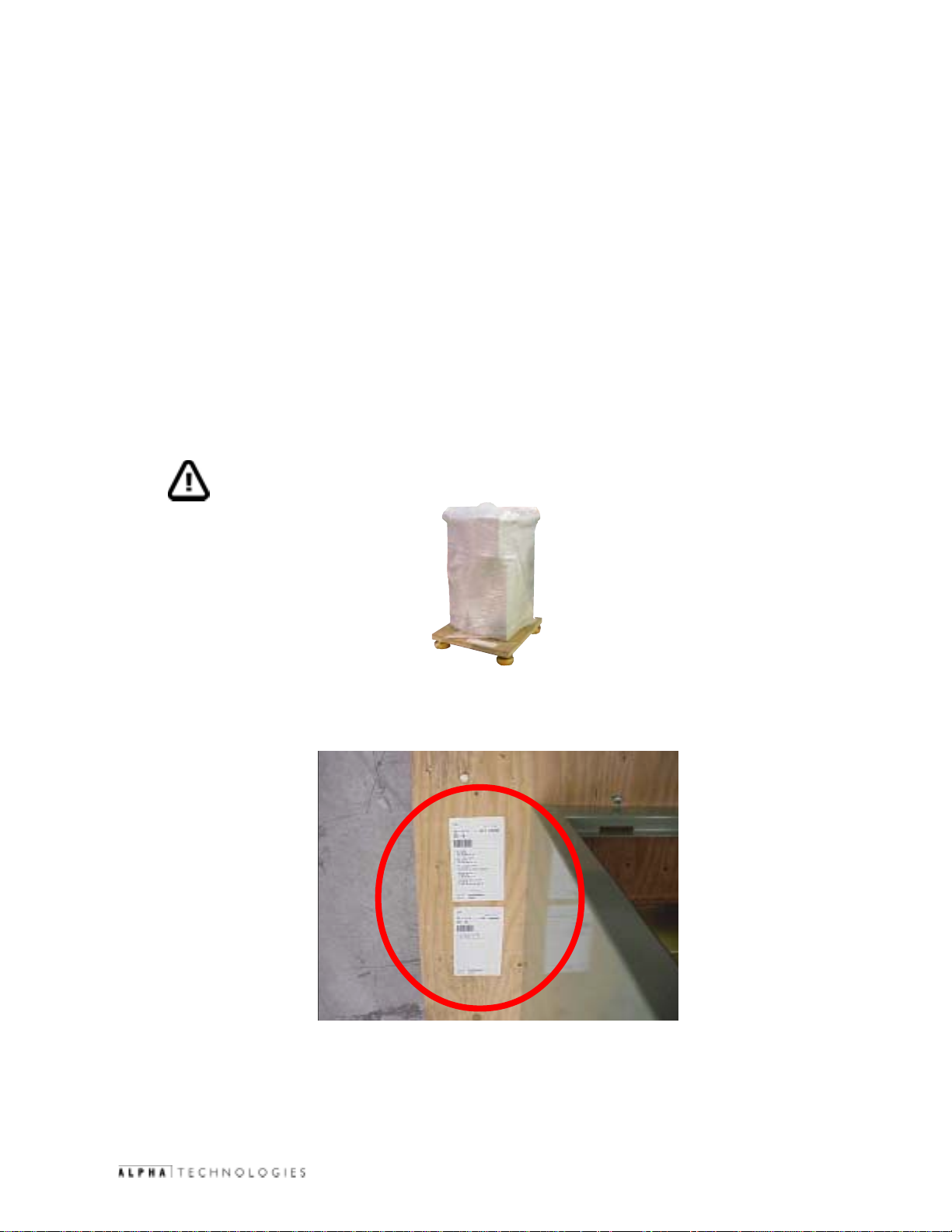
Unpacking and Inspection:
Carefully remove the enclosure from the shipping container. Verify that:
• The correct unit was shipped (either Alpha PN-3 or PN-4 enclosure).
• Ordered options have been included. (Refer to packing label details located on wooden pallet. See
figure 1-2)
NOTE: Batteries are shipped separately.
1. Introduction
Figure 1-1; Enclosure as it Arrives from Alpha
Figure 1-2; Packing Label Location
Inspect the contents. If items are damaged or missing, contact Alpha Technologies and the shipping company immediately .
Most shipping companies have only a short claim period.
© 2002
TM
9
031-103-B0-003 Rev. C
Page 10
1. Introduction
1.2 PN-3 and PN-4 Powernode Enclosure
Alpha's PN Series Power Module enclosures offer complete flexibility and modular expendability for Cable TV powering
applications. The Modular Tray system simplifies installation while allowing for future expansion or reconfiguration. The PN
Series is designed to accommodate current system power requirements while allowing the cost-effective addition of power
capacity, as well as enhanced reliability options, when new services are integrated. Excellent for either distributed or
centralized powering architectures, PN Series enclosures are available to accommodate multiple power supplies, battery
strings and/or natural gas or propane generators
Power Supply Capacity: Up to three power supplies (6kW)
Weight: 100-170 lbs ( depending on options)
Figure 1-3; PN-3 Specifications
Dimensions: 26" W x 44" H x 24" D
Material: Aluminum, .080-.125 inches
Power Supply Capacity: Up to three power supplies (6kW)
031-103-B0-003 Rev. C
Figure 1-4; PN-4 Specifications
Dimensions: 26" W x 52" H x 24" D
Weight: 110-180 lbs ( depending on options)
Material: Aluminum, .080-.125 inches
10
© 2002
TM
Page 11
2. Pre-Installation
2.1 Site Preparation
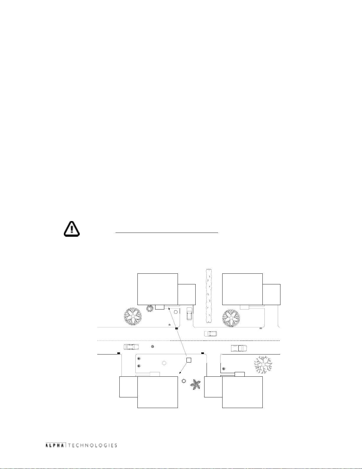
The site must be planned so that the enclosure will receive good air flow. If possible, in areas of extreme heat, it is best to
position the enclosure so that it will be shaded from the afternoon sun. In areas of prevailing winds, it is best that the
enclosure be located so that the sides of the cabinet face the winds instead of the doors. This will greatly reduce the buildup
of sand or snow against the enclosure’s air vents.
In areas of potential flooding, the geographical site and concrete pad must be located above the flood plain. Pedestals are
available to raise the Power Node enclosures above expected snow and water levels.
The enclosure must be placed where it will be free of obstructions, allowing easy access to the doors for service or equipment
access. For ventilation and maintenance, allow a minimum space of 36 inches in the front and 36 inches in the rear, between
the enclosure and other solid structures.
Place the enclosure well away from ground level sources of forced water, such as underground sprinkler systems and direct
roadway splash.
The concrete pad drawing is provided in the Pre-Installation Section of this manual contains all of the required mounting
details, including electrical service and cable plant entrances.
The vapor barrier material (such as 30 lb. felt, neoprene pond liner, or heavy grade tar paper) must initially extend at least
6" in all directions around the perimeter of the enclosure and be trimmed closer to the enclosure, using the appropriate utility
knife or cutting tool.
WARNING:
Never transport the unit with batteries installed. Batteries must ONL Y be installed after the
unit is transported to the site and secured to the pad. Transporting the unit with batteries
installed may cause a short circuit, fire, explosion, and/or damage to the battery pack,
enclosure and installed equipment. Damage caused by improper shipping or transporting a
unit with batteries installed is not covered under warranty.
House
50 feet
PN-3/4
House
© 2002
25 feet
House
Figure 2-1; Suggested Site Selection, PN-3 and PN-4
TM
11
House
031-103-B0-003 Rev. C
Page 12
2. Pre-Installation
2.2 Concrete Pad Preparation
Pads can either be poured on site, or precast by Alpha Technologies. A vailable concrete pad configurations and part numbers
can be found in section 5, "Alpha Part Numbers".
5
1
4
7
2
8
6
7
Figure 2-2; Single-Wide Concrete Pad for PN-3 and PN-4
All dimensions shown in inches. Mounting holes and sweeps indexed from this position.
1
Indicates PN-3 and PN-4 pedestal enclosure mating surface.
2
3
3
4
5
6
7
8
031-103-B0-003 Rev. C
Alpha standard; recommended distance (6" minimum) between edge of pad and cabinet.
Four inch diameter hole for AC power IN (non-metered installation).
Four inch diameter opening for DC Output cable and Status Monitoring harness.
All mounting hardware must be stainless, galvanized, or better to prevent corrosion.
5" x 8" rectangular cutout (2 places), open area for all internal connections including: generator power
and/or coax cable conduit sweeps.
A 25+ year continuous vapor barrier must be used between the enclosure and the pad to prevent
moisture ingress and possible corrosion caused by metal to concrete contact. The vapor barrier material
(such as 30 lb felt, neoprene pond liner, or heavy grade tar paper) must be initially extended at least 6"
in all directions around the perimeter of the enclosure. After the enclosure is secured to the pad, the
material can be cut closer to the enclosure, using the appropriate knife or cutting tool.
12
© 2002
TM
Page 13
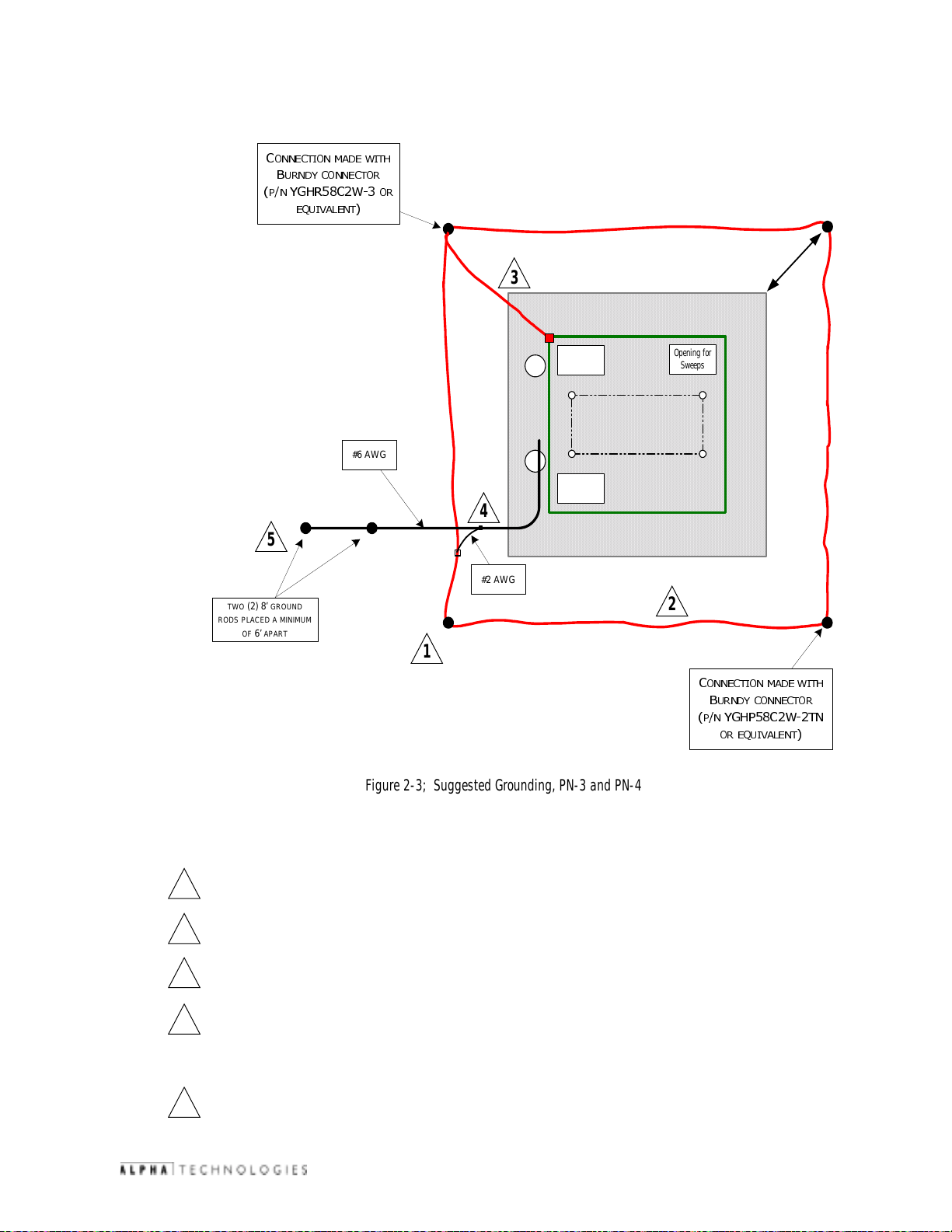
2.3 Enclosure Grounding
&
211(&7,210$'(:,7+
%
851'<&211(&725
31<*+5&:
(48,9$/(17
#6 AWG
25
2. Pre-Installation
2 feet
min)
3
Enclosure Footprint
Opening for
Sweeps
Opening for
Sweeps
Opening for
Sweeps
4
(
5
#2 AWG
TWO (2) 8’ GROUND
PLACED A MINIMUM
RODS
6’ APART
OF
2
1
Figure 2-3; Suggested Grounding, PN-3 and PN-4
Lightning Protection (Optional)
1/2" x 8' copper ground rod, four places, driven about 2 feet (typical) from the corners of the pad.
1
#2 bare copper wire loop terminated to each ground rod and buried below grade 2 to 12 inches.
2
Corrosion-proof connections (25+ year life-span) and hardware suitable for direct burial MUST be used
#2 bare copper wire from loop to the enclosure
3
&
211(&7,210$'(:,7+
%
851'<&211( &7 25
31<*+3&:71
25(48,9$/(17
© 2002
When the electrical supply is a primary service (not a secondary or feeder service) a #2 bare copper wire
4
must be bond the lightning protection loop to the Grounding Electrode Conductor where they are closest.
Service Grounding (required)
#6 bare copper wire from Service Neutral / Ground Bar with 2 ground rods located 6' apart.
5
TM
13
031-103-B0-003 Rev. C
Page 14
2. Pre-Installation
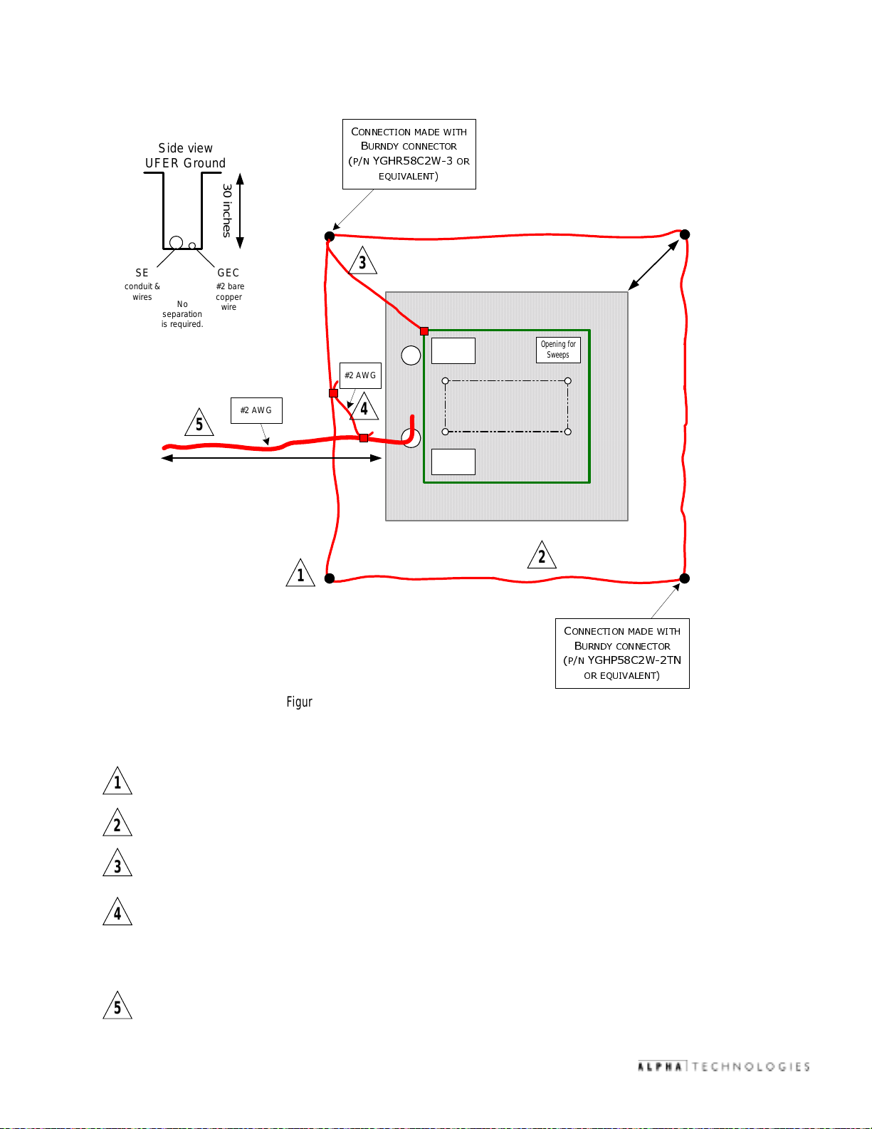
2.3 Enclosure Grounding,
Side view
UFER Ground
30 inches
SE
conduit &
wires
separation
is required.
GEC
#2 bare
copper
No
wire
5
20 feet (minimum)
#2 AWG
continued
&
211(&7,210$'(:,7+
%
31<*+5&:
3
#2 AWG
4
851'<&211(&725
(48,9$/(17
Opening for
Sweeps
Opening for
Sweeps
25
Enclosure Footprint
Opening for
Sweeps
t
e
e
f
n)
i
2
(m
2
1
&
211(&7,210$'(:,7+
%
31<*+3&:71
Figure 2-4; Alternate Grounding, PN-3 and PN-4
Lightning Protection (Optional)
1/2" x 8' copper ground rod, four places, driven about 2 feet (typical) from the corners of the pad.
1
#2 bare copper wire loop terminated to each ground rod and buried below grade 2 to 12 inches.
2
Corrosion-proof connections (25+ year life-span) and hardware suitable for direct burial MUST be used.
#2 bare copper wire from loop to the enclosure
3
When the electrical supply is a primary service (not a secondary or feeder service) a #2 bare copper wire
4
must be bonded to the lightning protection loop to the Grounding Electrode Conductor where they are
closest.
Service Grounding (required)
851'<&211(&725
25(48,9$/(17
5
031-103-B0-003 Rev. C
#2 bare copper wire from Service Neutral / Ground Bar down 30 inches and out 20 feet beyond the pad
edge. This is often called a UFER ground (Ground Ring in the NEC).
14
© 2002
TM
Page 15

3. Installation
3.1 T ransportation and Lifting
The PN-3 or PN-4 cabinet as shipped weighs approximately 100-150 lbs. A safe means of transportation to the site and a
safe procedure for unloading the enclosure is necessary. Do not transport or lift with a device that may not be able to bear
the unit's weight, and do not place the unit upon a surface that will not be able to fully support it.
NOTE: Enclosure must always remain in the upright position during the shipping, storage and installation
process. Damage may result from enclosure being shipped or stored on its side.
NOTE: Electronic modules, batteries or other components must not be installed until the enclosure is securely
set in place at its permanent location.
3.2 Enclosure Mounting Procedure
The enclosure bolts directly to the concrete pad. Mounting holes are provided in the base of the internal enclosure rack to
accommodate the pad’s 3/8" stainless or galvanized anchor bolts.
1. Place vapor barrier material on pad and make cutouts for anchoring hardware and other openings as
necessary. A 25+ year vapor barrier
moisture ingress and to prevent corrosion caused by concrete-to-metal contact.
MUST be used between the concrete and enclosure base to inhibit
2. With no less than two field personnel lifting the enclosure, position it above the concrete pad and slowly
lower it into position over the pad's 3/8" anchor bolts.
3. Secure the enclosure using stainless, galvanized (or better) flat washers, lock washers and 3/8" nuts at
each mounting bolt.
NOTE: Enclosures must be mounted flush with a smooth surface. If the concrete pad is uneven or has
bumps, cracks or other imperfections, the installer is responsible for correcting these defects prior
to installing the enclosure.
4. Install electronic modules and batteries at this time.
26"
44"
© 2002
6"
38"
3 " to 6"
Figure 3-1; PN-3 Mounted to the Prepared Pad
TM
15
031-103-B0-003 Rev. C
Page 16

3. Installation
3.3 Utility Powering
The XM2 Power Supplies are powered by either 120VAC or 240VAC (depending upon the model), attached to an external
service entrance. The size of the service conductors must be based upon the actual size of the utility service and be in
accordance with applicable electrical code requirements.
The utility conduit may be placed in one of two locations, depending upon the utility service entrance requirements. Note the
optional conduit location for use with meter base and the standard location for entry directly to the load center.
Proper grounding is critical. The enclosure MUST have a hard-wired ground to the service entrance. A qualified electrician
will need to verify that grounding is in compliance with applicable electrical codes. (Refer to section 2.3, "Enclosure
Grounding".
NOTE: All applicable codes must be adhered to when installing a system, pouring concrete, or placing a
preformed pad. These codes supersede any procedures outlined in this document.
NOTE: All mounting hardware must be
conditions. Use of improper hardware may cause corrosion, which is not covered under warranty.
NOTE: Soil conditions vary and may affect the integrity of the pad. Alpha Technologies r ecommends that
proper steps be taken to ensure that the soil supporting the pad is stable. Improper installation
of the pad may cause uneven settling or cracking, which is not covered under warranty.
Both standard and EUSERC style meter bases are available for some configurations as illustrated in the following
figures. Consult Alpha Technologies or your local representative regarding compatibility with your specific application.
CAUTION: The following utility powering procedures must be performed only by qualified service personnel
and in compliance with local electrical codes.
Verify electrical codes prior to installation. Codes may vary and contain specific conduit and wire sizes for
connection to the service entrance.
Connection to utility power must be approved by the local utility before installing the power supply.
The enclosure is equipped with a Square D, rainproof service entrance (SUSE rated). The service entrance is equipped with
a circuit breaker for a 120/240VAC, split phase, 3-wire w/GND source.
Materials Required:
stainless
or
galvanized
, depending on local environmental
031-103-B0-003 Rev. C
1" diameter conduit (or larger)- PVC or Galvanized Steel (threaded)
#6 AWG - Red /stranded insulated wire
#6 AWG - Black / stranded insulated wire
#6 AWG - White / stranded insulated wire
#2 AWG or larger - Stranded copper ground wire
16
© 2002
TM
Page 17

3. Installation
3.3 Utility Powering,
continued
3.3.1 Connection Procedure for the BBX-100A-8POS Service Disconnect:
1. Locate the service entrance panel on the enclosure (exterior). Remove the cover to access the circuit
breaker assembly. If this service panel is to be used as the primary service entrance, neutral must be
bonded to ground by installing the green ground screw (provided) in the hole in the neutral bus.
2. Remove the knockout located at the base of the service entrance to accept the conduit.
3. Install the conduit nipple into the service entrance via the knockout and secure with the appropriate
threaded conduit locknut.
4. Locate the two screw terminals (L1 and L2) on the bottom of the input circuit breaker.
5. Connect one of the incoming Black #6 AWG wires to L1 (left terminal). Connect the remaining Black (or
Red) #6 AWG wire to L2 (right terminal). NOTE: If the wire at L2 is Black, Mark it with red tape (or label).
6. Connect the #6 AWG White wire to the neutral (N) bus lug located to the top right of the circuit breaker
assembly.
7. Connect the #6 Bare solid or stranded for Grounding Electrode Conductor (Earth Ground) to the ground
and neutral bus located to the right side of the circuit breaker assembly.
8. Notify the electrical inspector to approve the service entrance wiring. Once approved, contact the local
power utility for electrical service.
1
Neutral
Grounding Electrode
Conductor
Line 1
Line 2
© 2002
Figure 3-2; BBX-100A-8POS Service Disconnect
Bond made by bonding screw only if no other service panel is used. (Must be installed on site only if this
1
is the primary service entrance.)
TM
17
031-103-B0-003 Rev. C
Page 18

3. Installation
3.3 Utility Powering,
continued
3.3.2 Connection Procedure for the BBX-70A Service Disconnect:
1. Locate the service entrance panel on the enclosure (exterior). Remove the cover to access the circuit
breaker assembly. If this service panel is to be used as the primary service entrance, neutral must be
bonded to ground by installing the green ground screw (provided) in the hole in the neutral bus.
2. Remove the knockout located at the base of the service entrance to accept the conduit.
3. Install the conduit nipple into the service entrance via the knockout and secure with the appropriate
threaded conduit locknut.
4. Locate the two screw terminals (L1 and L2) on the top of the input circuit breaker.
5. Connect one of the incoming Black #6 AWG wires to L1 (left terminal). Connect the remaining Black (or
Red) #6 AWG wire to L2 (right terminal). NOTE: If the wire at L2 is Black, mark it with red tape (or label).
6. Connect the #6 AWG White wire to the neutral (N) bus lug located to the top right of the circuit breaker
assembly.
7. Connect the #6 Bare solid or stranded for Grounding Electrode Conductor (Earth Ground) to the ground
and neutral bus located to the right side of the circuit breaker assembly.
8. Notify the electrical inspector to approve the service entrance wiring. Once approved, contact the local
power utility for electrical service.
Neutral
Line 1
1
Line 2
Grounding Electrode
Conductor
1
031-103-B0-003 Rev. C
Figure 3-3; BBX-70A Service Disconnect
Bond made by bonding screw only if no other service panel is used. (Must be installed on site only if this
is the primary service entrance.)
18
© 2002
TM
Page 19

3. Installation
3.3.3 Sample Input Power Panels
For more information on available models of the Input Power Panel, refer to "PN Series Options", section 4.4.
From
Service
Supply
Grounding
Electrode
Conductor
Lightning
Protection
Service and
Distribution
Service
Main
Line 1
Line 2
Neutral
50A
N
Main Bonding Jumper
G
Primary Service:
1) Main Bonding Jumper is Installed.
2) Grounding Electrode Conductor is Installed.
3) Lightning Protection is bonded outside of cabinet.
15A
15A
15A
BBX-100A-8POS
Load
IPP-240-3
120V/15A
GFCI
240V/15A
240V/15A240V/15A
From
Service
Supply
Grounding
Electrode
Conductor
Lightning
Protection
Figure 3-4; Schematic: Primary Service BBX-100A-8POS with IPP-240-3
Service and
Distribution
Service
Main
Line 1
Line 2
Neutral
50A
N
Main Bonding Jumper
G
Primary Service:
1) Main Bonding Jumper is Installed.
2) Grounding Electrode Conductor is Installed.
3) Lightning Protection is bonded outside of cabinet.
Figure 3-5; Schematic: Primary Service BBX-100A-8POS with IPP-120-3
15A
20A
20A
20A
BBX-100A-8POS
Load
120V/20A 120V/20A 120V/20A 120V/15A
GFCI
IPP-120-3
© 2002
TM
19
031-103-B0-003 Rev. C
Page 20

3. Installation
3.3.3 Sample Input Power Panels,
Service and
Distribution
From
Feeder
Supply
Main
Disconnect
Line 1
Line 2
Neutral
Equipment
Grounding
Conductor
N
NO Main Bonding Jumper
G
Secondary Service:
1) Main Bonding Jumper is NOT Installed.
2) Grounding Electrode Conductor is NOT Installed.
3) Lightning Protection is part of feeder supply.
20A
20A
15A50A
BBX-100A-8POS
continued
Load
IPP-120-2
120V/15A
GFCI
120V/20A 120V/20A
From
Feeder
Supply
Figure 3-6; Schematic: Secondary Service BBX-100A-8POS with IPP-120-2
Service and
Distribution
Main
Disconnect
Line 1
Line 2
Neutral
Equipment
Grounding
Conductor
50A
N
NO Main Bonding Jumper
G
Secondary Service:
1) Main Bonding Jumper is NOT Installed.
2) Grounding Electrode Conductor is NOT Installed.
3) Lightning Protection is part of feeder supply.
Load
15A
15A
15A
120V/15A 240V/15A240V/15A
BBX-100A-8POS
GFCI
031-103-B0-003 Rev. C
IPP-240-2
Figure 3-7; Schematic: Secondary Service BBX-100A-8POS with IPP-240-2
20
© 2002
TM
Page 21

3. Installation
3.3.3 Sample Input Power Panels,
Service and
Distribution
From
Feeder
Supply
Line 1
Line 2
Neutral
Equipment
Grounding
Conductor
15A
20A
N
NO Main Bonding Jumper
G
BBX-70A
Secondary Service:
1) Main Bonding Jumper is NOT Installed.
2) Grounding Electrode Conductor is NOT Installed.
3) Lightning Protection is part of feeder supply.
continued
Load
120V/20A 120V/15A
GFCI
IPP-120-1
From
Service
Supply
Grounding
Electrode
Conductor
Lightning
Protection
Figure 3-8; Schematic: Secondary Service BBX-70A with IPP-120-1
Service and
Distribution
Line 1
Line 2
Neutral
20A
N
Main Bonding Jumper
G
Primary Service:
1) Main Bonding Jumper is Installed.
2) Grounding Electrode Conductor is Installed.
3) Lightning Protection is bonded outside of cabinet.
BBX-70A
Load
IPP-240-1
120V/15A
GFCI
240V/15A
© 2002
Figure 3-9; Schematic: Primary Service BBX-70A with IPP-240-1
TM
21
031-103-B0-003 Rev. C
Page 22

3. Installation
3.4 Coaxial Cable to Service Power Inserter (SPI) Installation
3.4.1 SPI to Ground Bar Connection Procedure
Tools List:
1" Socket (3/8" drive)
3/8" Rachet
#2 Phillips Screwdriver
Zip Tie Gun
1). Install SPI by tightening the attached
coaxial connector to the equipment tray.
Figure 3-10; Connector Fitting in Rear of Equipment Tray
2). Secure SPI ground wire to the SPI with
attached screw, and connect to enclosure
ground bar.
3). Terminate stripped end of wire at enclosure
ground bar.
Figure 3-12; SPI Ground Wire Connected to Enclosure Ground Bar
Figure 3-11; Location of SPI in Equipment Tray
031-103-B0-003 Rev. C
22
© 2002
TM
Page 23

3. Installation
3.4.2 Conduit Placement
Conduit location is in the back of the enclosure, on the right side. (Location is specified on concrete pad.)
Figure 3-13; Conduit Location
Figure 3-14; Coaxial Connectors
© 2002
TM
23
031-103-B0-003 Rev. C
Page 24

3. Installation
3.5 Battery Installation
3.5.1 Battery Safety Notes
Electrical Hazards
Battery systems represent a risk of electrical shock and high short circuit currents. The following precautions
must be observed when maintaining batteries:
• Remove all personal metal objects (watches, rings, etc.)
• Use insulated tools.
• Wear eye protection and rubber gloves.
• Observe circuit polarities.
• Do not make or break live circuits.
• Do not lay metal tools and hardware on top of the batteries.
The battery is enclosed in cabinets with limited access. Again, extreme caution must be exercised when maintaining
and collecting data on the battery system.
Disposal
• Lead acid batteries are to be recycled. Batteries contain lead and dilute sulfuric acid. Dispose of in accordance
with Federal, State, and local regulations. Do not dispose of in a landfill, lake or other unauthorized location.
Chemical Hazards
• Any gelled or liquid emissions from a battery is electrolyte, and contains dilute sulfuric acid which is harmful to
the skin and eyes; is electrically conductive; and is corrosive.
• If electrolyte contacts the skin, wash immediately and thoroughly with water. If electrolyte enters the eyes, wash
thoroughly for 10 minutes with clean water or a special neutralizing eye wash solution and seek immediate medical
attention.
• Neutralize any spilled electrolyte with the special solutions contained in a “spill kit” or with a solution of 1 lb.
bicarbonate of soda to 1 gallon of water.
Fire, Explosion, and Heat Hazards
• Lead acid batteries can contain an explosive mixture of hydrogen gas which can vent under overcharging conditions.
• Do not smoke or introduce sparks in the vicinity of the battery.
• Do not charge batteries in a sealed container. The individual batteries must have 0.5 inches of space between
them to allow for convection cooling. If contained, assure the container or cabinet and room have adequate
ventilation to prevent an accumulation of potentially vented gas.
031-103-B0-003 Rev. C
24
© 2002
TM
Page 25

3. Installation
3.5.2 Battery Identification
Each battery contains a DATE CODE usually located near the positive (+) terminal of the battery. This date code
must be recorded in the maintenance log (
used, consult the battery manufacturers’ documentation for date code type and placement.
MAINTENANCE
manual). If batteries other than those installed by Alpha are
0702
MONTH: (JUL) 07
YEAR: 2002
Figure 3-15; Alpha Cell Battery Date Code
3.5.3 Battery Terminal Connections
The accompanying drawings are for
styles and hardware may be shipped with the system. ALWAYS refer to the battery manufacturer's specifications for
correct mounting hardware and torque requirements. During maintenance procedures, refer to the manufacturer's
specifications for the maintenance torque requirements.
Mounting hardware requirements may vary with battery manufacturers. Use only the hardware recommended by
your particular battery manufacturer.
NOTE: Use a corrosion inhibitor (such as NCP-2) on battery terminals.
illustrative
purposes only. Various types of batteries with different mounting
Battery Terminal
Battery Cable, and
Spacer
Crimp Connector to
next Battery
In-line Fuse Link
© 2002
Washers & Bolt
TM
Figure 3-16; In-Line Fuse Link Mounting
25
031-103-B0-003 Rev. C
Page 26

3. Installation
3.5.4 Battery Terminal Assembly Procedure
These illustrations show the Battery Terminal assembly for vertically mounted battery posts. Refer to the battery
manufacturers’ specifications for tightening torque.
Battery Cable
Flat Washer
Split Washer
Nut
Figure 3-17; Vertically Mounted Battery Post
Battery Terminal
Flat Washer
Bolt
3.5.5 Battery Installation Procedure
1. Place the batteries on their respective shelves as shown in Figure 3-18; "Battery Installation Arrangement"
on the next page.
2. Connect the three (or four) batteries in series (negative to positive) to achieve 36VDC (or 48VDC). Route
the battery cables inside the vertical rail for connection to the power supply. Terminal connectors must
be torqued to approximately 75 inch/pounds at installation and then re-torqued to 50 inch/pounds
during routine maintenance.
3. Use a voltmeter to verify polarity and DC voltage at the module's battery connector.
4. Mate the battery connectors to their respective sockets on the power supply module.
5. Number the batteries 1, 2, 3, (4) using labels, masking tape, or china marker. Record each battery's
6. For installations with multiple battery strings in parallel, each string must be fused. Verify that the
031-103-B0-003 Rev. C
NOTE: The cables are marked with a RED sleeve to indicate the (+) positive battery terminal.
CAUTION: Whenever making or breaking battery connections, never allow live battery cables to
contact the chassis. If necessary, wrap the lugs with electrical tape to prevent arcing
and temporarily disconnect one of the leads from the center battery. Check the battery
voltages at the connectors leading into the XM power supply.
NOTE: Ensure that voltage and polarity are correct before proceeding.
number and date code in the power supply's maintenance log.
enclosure was ordered with a fused Battery Cable Kit (BCK). For replacement fuses, or to add fuses to
a BCK without fuses, order the Battery Terminal Fuse Kit, Alpha part number SPB98-645-1.
26
© 2002
TM
Page 27

3.5.6 Battery Installation Layout
_
To "Battery Input"
+
3. Installation
Upper Battery Tray
1
2
36VDC configuration
_
To "Battery Input"
+
Fuse
Location
3
© 2002
Upper
Battery
Tray
12
4
Fuse
Location
3
48VDC configuration
Figure 3-18; Battery Installation Arrangement
TM
27
031-103-B0-003 Rev. C
Page 28

3. Installation
3.5.6 Battery Arrangement, Power Supply Connection,
Module Tray
_
+
XM Series Quick
Disconnect Battery
Connector
Upper Battery tray
continued
4
5
Lower Battery tray
1
6
Fuse
Location
2
3
Fuse
Location
031-103-B0-003 Rev. C
Figure 3-19; Wiring Diagram for two 36V Battery Strings — PN3 Enclosure
28
© 2002
TM
Page 29

3. Installation
3.5.6 Battery Arrangement, Power Supply Connection,
Module Tray
_
+
XM Series Quick
Disconnect Battery
Connector
Upper
Battery
8
tray
continued
5
Lower
Battery
tray
1
6
7
Fuse
Location
4
2
3
Fuse
Location
© 2002
Figure 3-20; Wiring Diagram for two 48V Battery Strings — PN3 Enclosure
TM
29
031-103-B0-003 Rev. C
Page 30

3. Installation
3.5.6 Battery Arrangement, Power Supply Connection,
Module Tray
_
+
XM Series Quick
Disconnect
Battery
Connector
Upper Battery tray
8
7
9
continued
Middle Battery tray
5
4
Lower Battery tray
2
1
Fuse
Location
6
Fuse
Location
3
Fuse
Location
031-103-B0-003 Rev. C
Figure 3-21; Wiring Diagram for three 36V Battery Strings — PN4 Enclosure
30
© 2002
TM
Page 31

3. Installation
3.5.6 PN4 Battery Arrangement, Power Supply Connection,
Module Tray
_
+
XM Series Quick
Disconnect
Battery
Connector
Upper
Battery
12
tray
10
9
11
continued
Fuse
Location
Middle
Battery
tray
5
Lower
Battery
tray
1
8
6
7
Fuse
Location
4
2
3
Fuse
Location
© 2002
Figure 3-22; Wiring Diagram for three 48V Battery Strings — PN4 Enclosure
TM
31
031-103-B0-003 Rev. C
Page 32

3. Installation
3.5.7 Battery Temperature Sensor
Sensor wiring connects to
Temperature Sensor Input connector of
XM2 Power Supply.
Use adhesive tape to attach the
sensor so that the flat side of the sensor
is flush to the side of the battery.
TM
®
Figure 3-23; Battery Temperature Sensor Mounting Location
To prevent incorrect temperature readings, attach the Battery Temperatur e Sensor associated with each XM2
Power Supply on different batteries.
031-103-B0-003 Rev. C
32
© 2002
TM
Page 33

4. PN Series Options
4.1 Star Lock Security Bolt
See section five, "Alpha Part Numbers" for PN Series options shown in this section.
The Star Lock Security Bolt kit comes factory installed when ordered with a new enclosure. The kit can also be added to
existing enclosures using the procedure below.
NOTE: The Security Key is a special tool that must be ordered separately. Alpha recommends ordering security
keys for each maintenance crew.
1). Drill dimple located approximately half way down enclosure doors.
®
Figure 4-1; Security Bolt Location
2). Place black clip over flange and align with factory-drilled hole in flange.
Figure 4-2; Black Clip in Place
3). Place bolt into hole, apply retaining washer, and tighten with Security Key.
© 2002
Figure 4-3; Retaining Washer Figure 4-4; Security Key (Part Number 647-089-10)
TM
33
031-103-B0-003 Rev. C
Page 34

4. PN Series Options
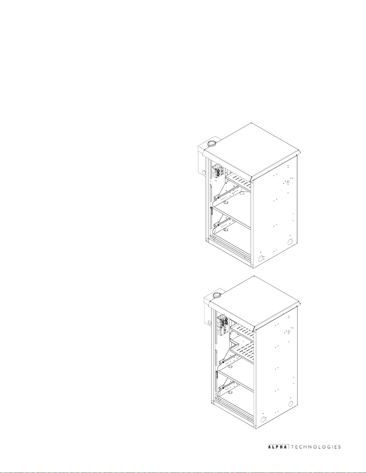
4.2 Battery Interface Unit (BIU)
The BIU is used in Powernode systems with multiple power supplies and/or multiple battery strings, and an AlphaGen DC
generator. The BIU provides a parallel DC bus with convenient connectors for each power supply and battery string.
(For installation and operation instructions, refer to the BIU Installation Manual, part number 018-311-C1.)
Upper battery shelf
Lower battery shelf (PN-3 enclosure)
Middle battery shelf (PN-4 enclosure)
Power Supply shelf
(optional mounting location for BIU)
BIU installed beneath
upper battery shelf
Figure 4-5; Battery Interface Unit in Place
4.3 Service Disconnects
There are four Service Disconnects available (installed at the factory):
For single power supply applications
031-103-B0-003 Rev. C
Square-D, 2-position
34
Figure 4-7; BBX 100A (BBX-FI8)Figure 4-6; BBX 70A (BBX-FI2)
Square-D, 8-position
For multiple power supply applications.
© 2002
TM
Page 35

4. PN Series Options
4.3 Service Disconnects,
Figure 4-8; MTS (Showing100A and 60A boxes)
For applications requiring
a protected AC generator.
continued
Figure 4-9; FBX-60A
Fused safety switch. For applications
with high AIC rating requirements.
4.4 Input Power Panel (IPP)
There are four basic configurations of the IPP. Each is available in 120V and 240V. Units in figures 4-10, 4-11, and 4-12
are factory pre-wired, include Square-D high-magnetic breakers for each power supply, and provide a GFCI convenience
outlet.
Figure 4-10; IPP for Three Power Supplies Figure 4-11; IPP for Two Power Supplies
© 2002
Figure 4-12; IPP for One Power Supply
TM
35
Figure 4-13; Breaker Duplex Option (BDO)
for One Power Supply
(NOT factory pre-wired.)
031-103-B0-003 Rev. C
Page 36

4. PN Series Options
4.5 Cooling Fan Kit
When using more than one power supply in the PN Series Enclosures, a cooling fan is required. The Cooling Fan kit includes
an intake filter, located inside the front door of the enclosure by the ventilation louvers. The filter must be cleaned
periodically as part of the power supply preventative maintenance program.
Replacement fuses and filters are available. Refer to section five for part numbers.
Connected to SPI
Figure 4-14; Cooling Fan Panel
Location of Fuse Holder
Figure 4-15; Panel is Installed in Top Rear of Enclosure
Connected to XM2
"Output 1"
031-103-B0-003 Rev. C
Figure 4-16; Cooling Fan Plugged into Power Supply and SPI
36
© 2002
TM
Page 37

4. PN Series Options
4.6 Lightning Arrester (LA-P+)
The Lightning Arrester is available in 120VAC and 240VAC, and is installed by plugging into an IPP or BDO.
Figure 4-17; LA-P+ Installed in BDO
The unit is operating properly when the green LED is lit.
Figure 4-18; Location of LED on LA-P+.
© 2002
TM
37
031-103-B0-003 Rev. C
Page 38

5. Alpha Part Numbers
5.1 PN Series Options
Item: Part Number:
Star Lock Security Bolt 744-897-20
Security Key 647-089-10
Battery Interface Unit (BIU) 018-311-24
Service Disconnects
BBX-70A 744-656-20
BBX-100A-8POS 744-657-20
MTS 240-40 SPB99-512-12
FBX-60A 744-534-20
Input Power Panels (IPP) (Pre-Wired)
IPP-CE, 1x240 1xGFCI 744-735-20
IPP-CE, 2x240 1xGFCI 744-701-20
IPP-CE, 3x240 1xGFCI 744-868-20
IPP-CE3x/9x 120V for BATT HTR 744-702-20
IPP-CE, 1x120 1xGFCI 744-735-21
IPP-CE, 2x120 1xGFCI 744-701-22
IPP-CE, 3x120 1xGFCI 744-868-21
IPP-CE, 3x120 1xGFCI 120Vin 744-868-22
BDO (NOT installed)
BDO-515 120V 15A Not SUSE Rated 744-148-20
BDO-520 120V 20A Not SUSE Rated 744-148-21
BDO-615 240V 15A Not SUSE Rated 744-147-21
Cooling Fan Kit 744-839-20
Replacement Fuse 460-025-10
Replacement Filter
Lightning Arrester
LA-P+ 120V (L-N, L-G, N-G) 020-098-24
LA-PC+ 120V (L-N, L-G, N-G) 020-098-26
LA-PE+ 240V (L1-L2, L1-G, L2-G) 020-098-25
Extra SPI (15 Amp) 744-279-22
Extra SPI (25 Amp) 744-789-21
NOTE: Alpha part numbers are correct at the time of printing. As part numbers are subject to
change, please contact your Alpha Representative prior to ordering to ensure that numbers
are correct.
031-103-B0-003 Rev. C
38
© 2002
TM
Page 39

5. Alpha Part Numbers
5.2 Pre-Cast Concrete Pads
Alpha offers a line or precast, polymer concrete and reinforced concrete pads for the PN Series Enclosures. Polymer
concrete is significantly lighter and more stable when compared to reinforced concrete. Both materials represent a significant
savings in labor costs and quality improvement over "pour-in-place" pads. Other precast pad configurations are available.
Contact your nearest Alpha representative for additional information.
+3.0
REF. 3.00
-0.0
0.000
0.25
+.25
-.125
REF.
© 2002
Figure 5-1; Single-Wide Pad, for CE8/9 or PN 3/4
Part Number:
PCD-3: 641-070-10 (Reinforced concrete)
PCC-3: 641-067-10 (Polymer concrete)
TM
39
031-103-B0-003 Rev. C
Page 40

5. Alpha Part Numbers
5.2 Pre-Cast Concrete Pads,
3.00 REF.
+3.0
0.000
-0.0
2
continued
0.25
+.25
-.125
REF.
1
1
4" diameter opening (2 plcs.)
Figure 5-2; Double-Wide Pad, for CE8/9 or PN 3/4
Part Number:
PCD 3-3: 641-072-10 (Reinforced concrete)
PCC 3-3: 641-069-10 (Polymer concrete)
2
031-103-B0-003 Rev. C
5" x 8" opening (6 plcs.)
40
© 2002
TM
Page 41

5. Alpha Part Numbers
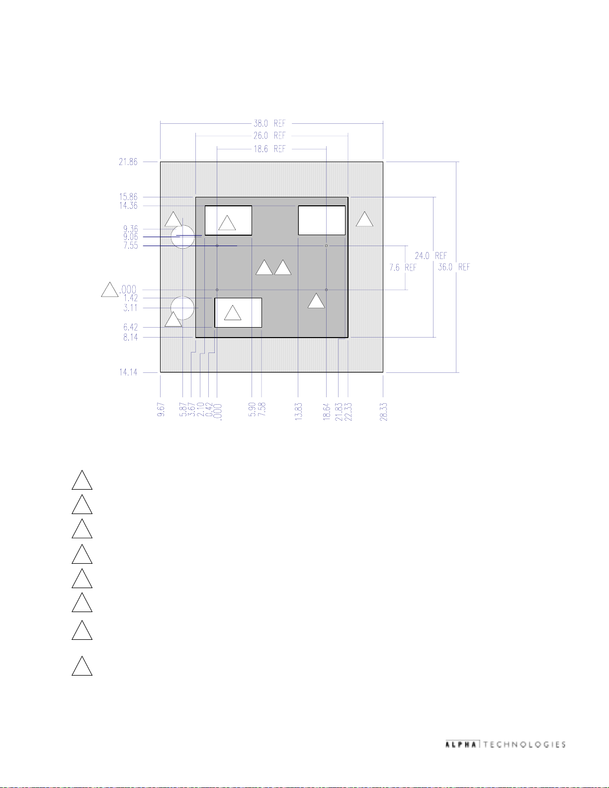
5.2 Pre-Cast Concrete Pads,
1
1.42
3.60
0.000
+3.0
-0.0
2
3.00 REF.
21.86
15.86
14.36
11.11
9.11
7.55
.000
3.11
continued
26 REF
18.6 REF
26 REF
19.5 REF
0.25
+.25
-.125
REF.
14.71 REF
7.6 REF
0.6
8.14
14.14
1
4
9
9
9
6
.
9
4
9
.
5
0
6
1
4
.
.
.
0
3
2
0
0
.
1
8
.
5
Figure 5-3; Double-Wide Pad, for CE 3x2/9x2 and CE8/9 or PN 3/4
4" diameter opening (2 plcs.)
6
5
.
7
1
8
.
3
1
Part Number:
0
6
.
8
1
5
8
2
.
1
2
1
8
.
1
PCD 3-3x: 641-071-10-003
PCD 3-3x: 641-068-10-003
2
3
.
5
4
6
5
.
8
4
6
6
5
0
.
.
4
0
5
5
© 2002
5" x 8" opening (3 plcs.)
2
TM
41
031-103-B0-003 Rev. C
Page 42

Page 43

Page 44

www.alpha.com
Protecting The Power in Communications.
UNITED STATES
ASIA PACIFIC
LATIN AMERICA
Alpha Technologies
3767 Alpha Way
Bellingham, WA 98226
Tel: (360) 647-2360
Fax: (360) 671-4936
Web: www.alpha.com
CANADA
Alpha Technologies Ltd.
4084 McConnell Court
Burnaby, BC, V5A 3N7
Tel: (604) 430-1476
Fax: (604) 430-8908
UNITED KINGDOM
Alpha Technologies Europe, Ltd.
Cartel Business Estate
Edinburgh Way
Harlow, Essex CM20 2TT
Tel: +44-1279-422110
Fax: +44-1279-423355
GERMANY
Alpha Technologies
Hansastrasse 8
Schwabach D-91126
Tel: +49-9122-79889-0
Fax: +49-9122-79889-21
MIDDLE EAST
Alphatec, Ltd.
339 St. Andrews St., Suite 101
Andrea Chambers
Limassol, Cyprus
Tel: +357-25-375675
Fax: +357-25-359595
AUSTRALIA
Alpha Technologies
8 Anella Ave., Unit 6
Castle Hill, NSW 2154
Tel: +61-2-9894-7866
Fax: +61-2-9894-0234
TM
Copyright © 2002 Alpha Technologies, Inc. All rights reserved. Alpha is a registered trademark of Alpha Technologies. 031-103-B0-003 Rev. C.
Due to continuing product improvements, Alpha reserves the right to change specifications without notice.
 Loading...