

Page 1
PWE/PME Series
Pole and Ground-mount Enclosures
PWE/PME Series Technical Manual
Effective: April 2009
Alpha Technologies
®
Page 2

Alpha Technologies
Power
®
Page 3

PWE/PME
Technical Manual
031-161-B0-006, Rev. F
Effective Date: April 2009
Copyright© 2009
Alpha Technologies, Inc.
member of The Group
NOTE:
Photographs contained in this manual are for illustrative purposes only. These photographs may not match
your installation.
NOTE:
Operator is cautioned to review the drawings and illustrations contained in this manual before proceeding. If
there are questions regarding the safe operation of this powering system, please contact Alpha Technologies
or your nearest Alpha representative.
NOTE:
Alpha shall not be held liable for any damage or injury involving its enclosures, power supplies, generators,
batteries, or other hardware if used or operated in any manner or subject to any condition not consistent with
its intended purpose, or installed or operated in an unapproved manner, or improperly maintained. Alpha polemount enclosure systems are designed for static applications.
TM
To contact Alpha Technologies:
Visit www.alpha.com
or
For general product information and customer service (7 AM to 5 PM, Pacifi c T ime), call
1-800-863-3930
For complete technical support, call
1-800-863-3364
7 AM to 5 PM, Pacifi c Time or 24/7 emergency support
To report errors in this document, send an email to:
Techpubs@alpha.com
3
Page 4

List of Tables and Figures
Safety Notes ..........................................................................................................................6
1.0 Introduction .................................................................................................................9
1.1 PWE/PME Series Enclosures ........................................................................ 10
1.2 PWE Enclosure Diagram ................................................................................11
1.3 Optional Features .......................................................................................... 12
1.4 The Battery Integration Tray .......................................................................... 13
1.5 PWE Battery Tray Latch Operation (optional) ................................................14
1.6 PWE Lid Removal .......................................................................................... 15
1.7 PWE/PME Enclosure Specifi cations ..............................................................15
1.8 PWE Legacy Models...................................................................................... 15
2.0 Installation.................................................................................................................16
2.1 Pole-mounting ................................................................................................16
2.1.1 Wooden Pole ....................................................................................... 16
2.1.2 Concrete or Steel Pole ........................................................................18
2.1.3 Enclosure Grounding: Pole-mount ......................................................20
Ground-mount Installation, PWE-4, PWE-8, PWE-9, PWE-D36 .....................21
2.2
2.2.1 Pre-Installation .................................................................................... 21
2.2.2 Enclosure Grounding: Ground-mount ................................................. 23
2.2.3 Ground-mount Installation, PWE-3, PWE-9 and PWE-D36 ................24
2.2.4 PWE-4 and PWE-8 Ground-mount Installation ...................................26
2.3 Connecting Utility Power ................................................................................ 28
2.4 Connecting the Coaxial Cable ....................................................................... 35
2.4.1 Coaxial Cable Surge Protector Installation Instructions ......................35
2.4.2 Connecting the Service Power Inserter (SPI) ..................................... 36
2.5 Battery Installation ......................................................................................... 37
2.5.1 Battery Date Code Usage and Identifi cation ....................................... 37
2.5.2 Battery Installation Procedure ............................................................38
2.5.3 Connecting the Battery Integration Tray (PWE 3/6 Only)....................39
2.5.4 Battery Terminal Connections ............................................................. 40
2.5.5 Battery Wiring Diagrams ....................................................................42
2.6 Installing the XM Series 2 Power Supply .......................................................47
2.7 Cooling Fan Installation ................................................................................. 48
2.8 PWE-8 Solar Shield Installation .....................................................................49
2.9 Status Monitoring Transponder Bracket Installation Instructions ................... 50
3.0 Pole-mount Enclosure Maintenance ......................................................................... 51
031-161-B0-006, Rev. F4
Page 5

List of Tables and Figures
Fig. 1-1, PWE-6 Enclosure ................................................................................................................................. 9
Fig. 1-2, PWE/PME Series Enclosures ............................................................................................................ 10
Fig. 1-3, PWE-3 Enclosure (confi gurations may vary).......................................................................................11
Fig. 1-4, Battery Integration Tray ...................................................................................................................... 13
Fig, 1-5, Opening the PWE Trays ..................................................................................................................... 14
Fig, 1-6, PWE Lid Removal .............................................................................................................................. 15
Fig. 2-1, PWE/PME Series Wooden Pole Mounting ......................................................................................... 17
Fig. 2-2, PWE/PME Series Steel or Concrete Pole Mounting .......................................................................... 19
Fig. 2-3, Enclosure Grounding for Pole-mount Confi guration........................................................................... 20
Fig. 2-4, Ground-mount Positioning and Safety ............................................................................................... 22
Fig. 2-5, Suggested Grounding Method ........................................................................................................... 23
Fig. 2-6, PWE-3, PWE-6, PWE-9, PWE-D36 Enclosure Pedestal ................................................................... 25
Fig. 2-7, Location of (4) Knockouts for Enclosure-to-Pedestal Mounting .........................................................25
Fig. 2-8, Access Holes for Front Bracket Mounting Locations .......................................................................... 26
Fig. 2-9, Ground Mounting Brackets, Installed ................................................................................................. 27
Fig. 2-10, Enclosure Ground-mount Footprint ................................................................................................. 27
Fig. 2-11, Enclosures Manufactured Before and After April 2002. .................................................................... 27
Fig. 2-12, Typical Service Entrance Wiring ....................................................................................................... 30
Fig. 2-13, Typical Receptacle Wiring ................................................................................................................ 30
Fig. 2-14, Typical ISE (Internal Service Entrance) Receptacle Wiring ............................................................. 31
Fig. 2-15, Typical BQO (Breaker Quad Option) Receptacle Wiring .................................................................. 32
Fig. 2-16, PWE Pole-mount Confi guration ....................................................................................................... 33
Fig. 2-17, Meter Wiring ..................................................................................................................................... 34
Fig. 2-18, 240Vac CSA Service Entrance Wiring .............................................................................................. 34
Fig. 2-19, 240Vac UL Service Entrance Wiring ................................................................................................ 34
Fig. 2-20, SPI Locations ................................................................................................................................... 34
Fig. 2-21, SPI ................................................................................................................................................... 36
Fig. 2-22, SPI (side view) ................................................................................................................................ 36
Fig. 2-23, Battery Date Code ............................................................................................................................ 37
Fig. 2-24, Battery Integration Tray Connections ............................................................................................... 39
Fig. 2-25, Threaded Insert Battery Terminal Connections ................................................................................ 40
Fig. 2-26, Flag Battery Terminal Connections .................................................................................................. 41
Fig. 2-27, PWE-3 (without BIT) and PME Battery Wiring Diagram...................................................................42
Fig. 2-28, PWE-4 Battery Wiring Diagram ........................................................................................................ 42
Fig. 2-29, PWE-6 Battery Wiring Diagram ........................................................................................................ 43
Fig. 2-30, PWE-D36 Battery Wiring Diagram .................................................................................................. 44
Fig. 2-31, PWE-8 Battery Wiring Diagram ....................................................................................................... 45
Fig. 2-32, PWE-9 Battery Wiring Diagram ........................................................................................................ 46
Fig. 2-33, XM Series 2 Power Supply............................................................................................................... 47
Fig. 2-34, Cooling Fan Kit Installed .................................................................................................................. 48
Fig. 2-35, PWE-8 Solar Shield Installation ....................................................................................................... 49
Fig. 2-36, Status Monitoring Bracket Location in PWE Series Enclosure ........................................................50
Table 1-1, PME/PWE Enclosure Specifi cations................................................................................................ 15
Table 2-1, Service Entrance Circuit Breaker Requirements ............................................................................. 28
5031-161-B0-006, Rev. F
Page 6

Safety Notes
Review the drawings and illustrations contained in this manual before proceeding. If there are any questions
regarding the safe installation or operation of this product, contact Alpha Technologies or the nearest Alpha
representative. Save this document for future reference.
To reduce the risk of injury or death, and to ensure the continued safe operation of this product, the following
symbols have been placed throughout this manual. Where these symbols appear, use extra care and
attention.
ATTENTION:
The use of ATTENTION indicates specifi c regulatory/code requirements that may affect the placement of
equipment and /or installation procedures.
NOTE:
A NOTE provide additional information to help complete a specifi c task or procedure.
CAUTION!
The use of CAUTION indicates safety information intended to PREVENT DAMAGE to material or
equipment.
WARNING!
WARNING presents safety information to PREVENT INJURY OR DEATH to the technician
or user.
031-161-B0-006, Rev. F6
Page 7

Battery Maintenance Guidelines
The battery maintenance instructions listed below are for reference only. Battery manufacturer’s instructions
for transportation, installation, storage or maintenance take precedence over these instructions.
• To prevent damage, inspect batteries every 3 months for:
Signs of battery cracking, leaking or swelling. The battery should be replaced immediately by
authorized personnel using a battery of the identical type and rating.
Signs of battery cable damage. Battery cable should be replaced immediately by authorized personnel
using replacement parts specifi ed by vendor.
Loose battery connection hardware. Refer to battery manufacturer’s documentation for the correct
torque and connection hardware for the application.
• Apply battery manufacturer’s specifi ed antioxidant compound on all exposed connections.
• Verify battery terminals and/or exposed connection hardware is not within 2 inches of a conductive
surface. Reposition batteries as necessary to maintain adequate clearance.
• Clean up any electrolyte (battery emission) in accordance with all federal, state, and local regulations or
codes.
• Proper venting of the enclosure is recommended. Follow the Battery Manufacturer’s approved
transportation and storage instructions.
• Always replace batteries with those of an identical type and rating. Never install old or untested batteries.
• Do not charge batteries in a sealed container. Each individual battery should have at least 0.5 inches of
space between it and all surrounding surfaces to allow for convection cooling.
• All battery compartments must have adequate ventilation to prevent an accumulation of potentially
dangerous gas.
Recycling and Disposal Instructions
Spent or damaged batteries are considered environmentally unsafe. Always recycle used batteries or dispose
of the batteries in accordance with all federal, state and local regulations.
Electrical Safety
• Lethal voltages are present within the power supply and electrical boxes. Never assume that an electrical
connection or conductor is not energized. Check the circuit with a volt meter with respect to the grounded
portion of the enclosure (both AC and DC) prior to any installation or removal procedure.
• Always use the buddy system when working under hazardous conditions.
• A licensed electrician is required to install permanently wired equipment.
• Input voltages can range up to 240Vac. Ensure that utility power is disabled before beginning installation
or removal.
• Ensure no liquids or wet clothes contact internal components.
• Hazardous electrically live parts inside this unit are energized from batteries even when the AC input
power is disconnected.
Mechanical Safety
• Keep hands and tools clear of fans. Fans are thermostatically controlled and will turn on automatically.
• Power supplies can reach extreme temperatures under load.
• Use caution around sheet metal components and sharp edges.
7031-161-B0-006, Rev. F
Page 8

Battery Safety Notes
WARNING!
Lead-acid batteries contain dangerous voltages, currents and corrosive material. Battery
installation, maintenance, service and replacement must be performed only by authorized
personnel.
Chemical Hazards
Any gelled or liquid emissions from a valve-regulated lead-acid (VRLA) battery contain dilute sulfuric
acid, which is harmful to the skin and eyes. Emissions are electrolytic, and are electrically conductive and
corrosive.
To avoid injury:
• Servicing and connection of batteries shall be performed by, or under the direct supervision of, personnel
knowledgeable of batteries and the required safety precautions.
• Always wear eye protection, rubber gloves, and a protective vest when working near batteries. Remove
all metallic objects from hands and neck.
• Batteries produce explosive gases. Keep all open fl ames and sparks away from batteries.
• Use tools with insulated handles, do not rest any tools on top of batteries.
• Batteries contain or emit chemicals known to the State of California to cause cancer and birth defects
or other reproductive harm. Battery post terminals and related accessories contain lead and lead
compounds. Wash hands after handling (California Proposition 65).
• Wear protective clothing (insulated gloves, eye protection, etc.) whenever installing, maintaining,
servicing, or replacing batteries.
• If any battery emission contacts the skin, wash immediately and thoroughly with water. Follow your
company’s approved chemical exposure procedures.
• Neutralize any spilled battery emission with the special solution contained in an approved spill kit or with
a solution of one pound Bicarbonate of soda to one gallon of water. Report chemical spills using your
company’s spill reporting structure and seek medical attention if necessary.
• All battery compartments must have adequate ventilation to prevent an accumulation of potentially
dangerous gas.
• Prior to handling the batteries, touch a grounded metal object to dissipate any static charge that may have
developed on your body.
• Never use uninsulated tools or other conductive materials when installing, maintaining, servicing or
replacing batteries.
• Use special caution when connecting or adjusting battery cabling. An improperly connected battery cable
or an unconnected battery cable can make contact with an unintended surface that can result in arcing,
fi re, or possible explosion.
031-161-B0-006, Rev. F8
Page 9
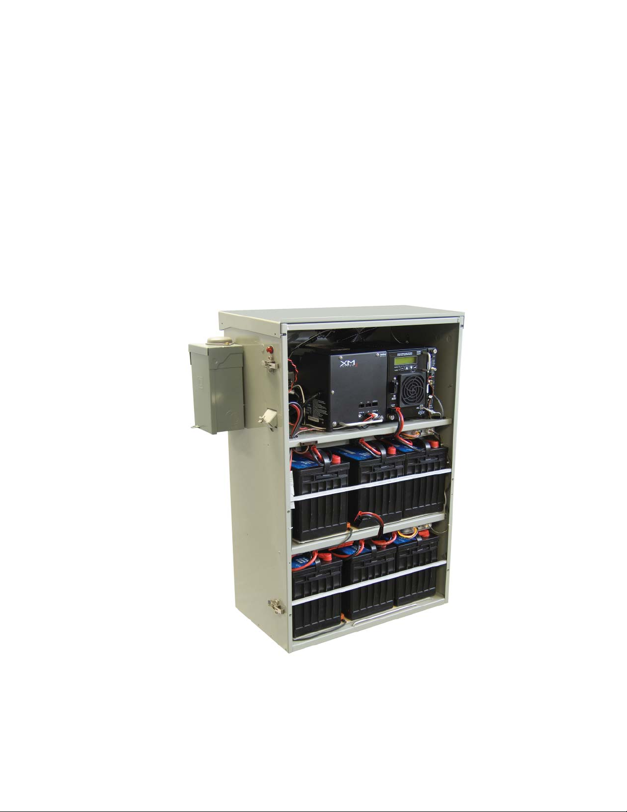
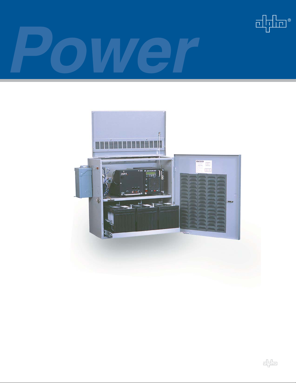
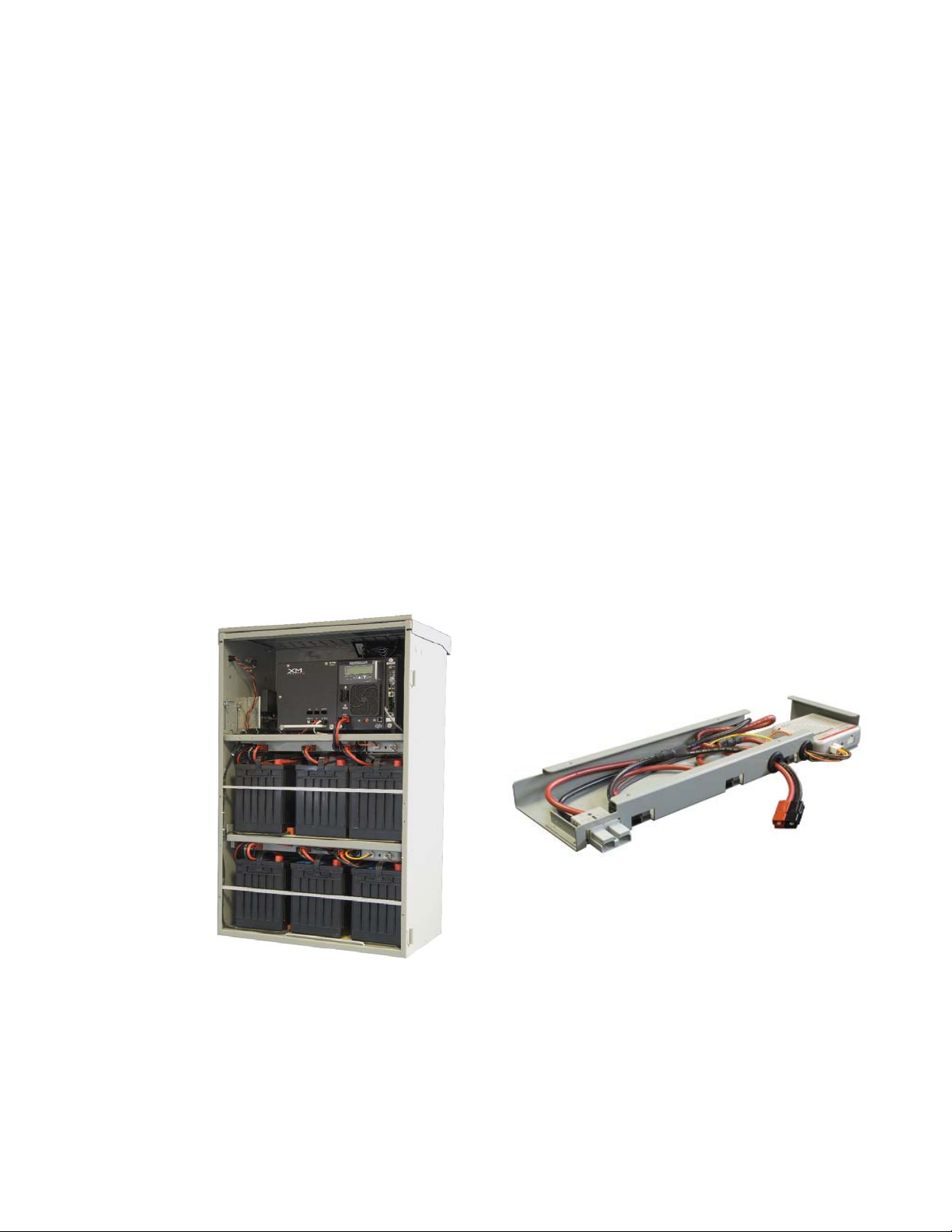
1.0 Introduction
PWE/PME Series enclosures support distributed powering architectures in pole and ground-mount
broadband applications. Ideal for use in all climates, each enclosure comes with a removable lockable
door and easy opening lid. Standard features include a high-magnetic circuit breaker, duplex AC
receptacle, and service power inserter.
Key Features:
• Engineered for broadband powering applications
• All aluminum welded construction and durable powdercoat fi nish
• Agency certifi ed to meet applicable industry standards
• Internal or external SUSE rated service entrance options
• Optional Battery Integration Tray (BIT) (PWE 3/6 only)
• Portable generator cabling access door
Fig. 1-1, PWE-6 Enclosure with BIT
9031-161-B0-006, Rev. F
Page 10
1.0 Introduction, continued
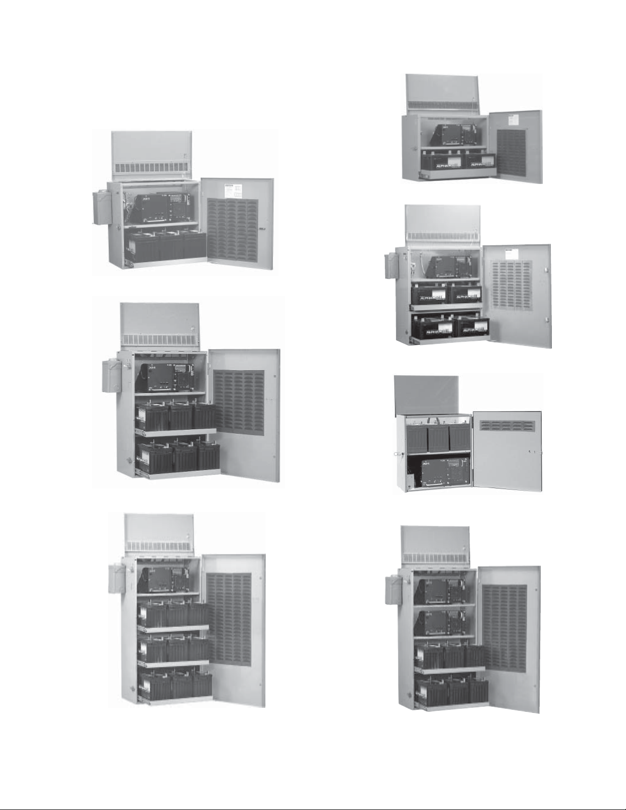
1.1 PWE/PME Series Enclosures
PWE-3
PWE-6
PWE-4
PWE-8
PWE-9
PME
PWE-D36
Fig. 1-2, PWE/PME Series Enclosures
031-161-B0-006, Rev. F10
Page 11
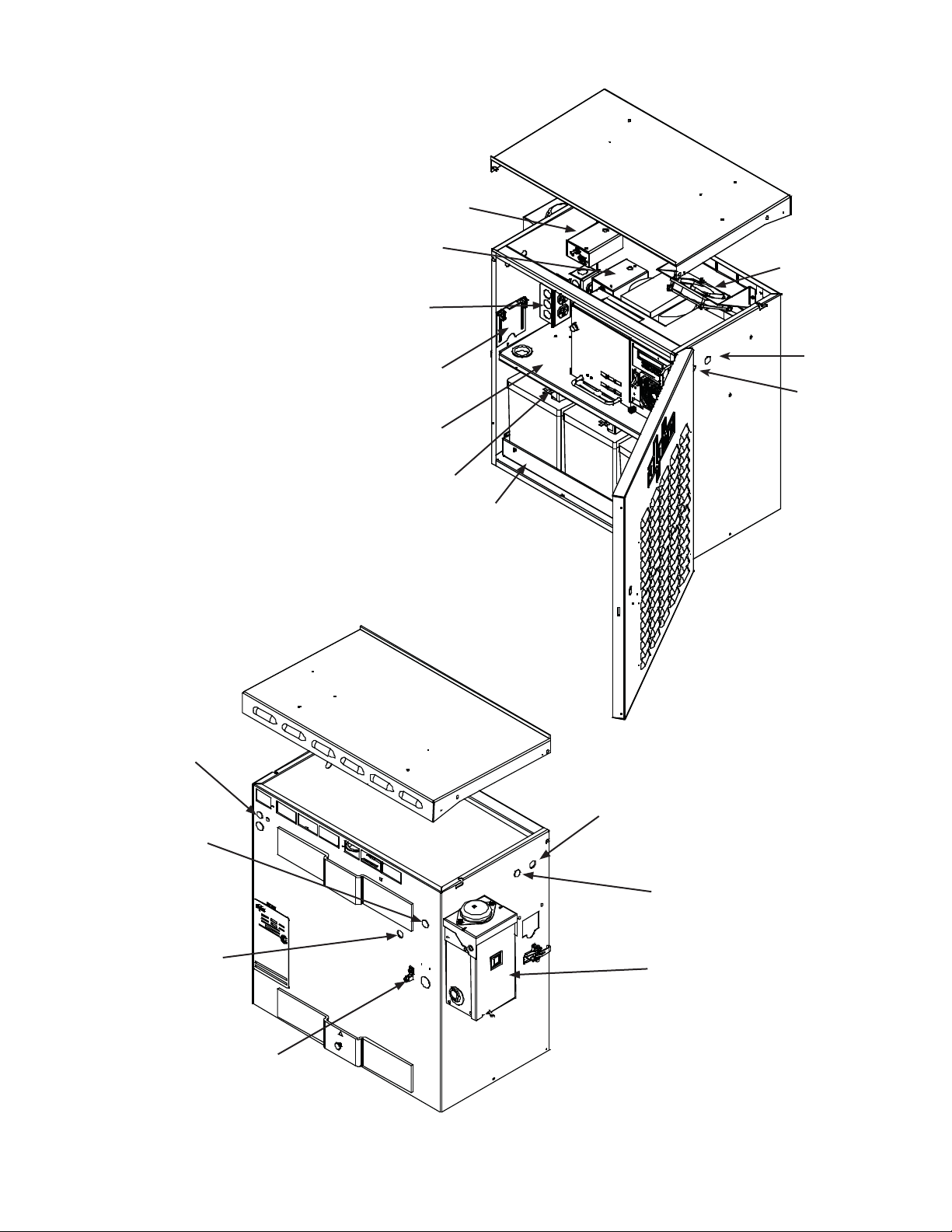
1.0 Introduction, continued
1.2 PWE Enclosure Diagram
Optional SPI
Front View
Rear View
Standard SPI
Location
Optional Duplex
Receptacle
Generator
Access Door
Power Supply Module Shelf
Optional Battery Integration Tray
Optional Battery
Slide Tray Assembly
Optional
Cooling Fan
ACI
LRI
Knockouts
for Status Monitoring
Optional SPI
Locations
Standard SPI
Location
External Ground Lug
Standard LRI Location
(optional knockout located on right side)
Optional ACI Location
(knockouts located on left and
right sides of enclosure)
Optional External Breaker Box
Fig. 1-3, PWE-3 Enclosure (confi gurations may vary)
11031-161-B0-006, Rev. F
Page 12

1.0 Introduction, continued
1.3 Optional Features
Feature Description
AC Indicator (ACI) The ACI verifies voltage output with a green light. Located next to the LRI
Battery Heater Mat (BHM) The BHM is AC line operated and turns on at 40°F. It increases battery
Battery Mat Option (BMO) The battery mat option provides additional battery cooling properties.
Battery Retaining Bar (BRB) The BRB provides additional security against batteries falling out of the
External Coax Raceway (ECR) The ECR conceals and protects the coaxial cables outside the PWE-9
Enclosure Cooling Fan (ECF) The ECF is a thermostat-controlled cooling system for PWE Series
Lightning Arrester-P+ (LA-P+) The LA-P+ provides protection against voltage spikes caused by lightning
Local Remote Indicator (LRI) The LRI is a red lamp which indicates when the power supply is running in
Module Retaining Cable (MRC) The MRC attaches the XM Series 2 power supply to the PWE Series
15A and 25A Service Power
Inserters (SPI)
Solar Shield Kit
(SSK)
Storm Hood Kit
(SHK)
Tamper Switch
(TMPR SW)
Coax Surge Protector Provides surge suppression for power supply.
External Generator Connector Allows a permanent generator connection point.
Battery Slide Tray Option allows access to battery cabling without removing batteries.
PWE High Security Device
(PHSD)
Ladder Bracket The ladder bracket option (Alpha P/N 745-095-21) easily attaches to all
AlphaGEM The AlphaGEM Generator Expansion Module is temporarily installed to
BE-PWE The BE-PWE expands battery backup capacity for PWE-3 enclosures. See
lamp on the outside of PWE/PME Series enclosures, it is easily monitored
from the ground. Because of its longer life, Alpha recommends the ACILL (long life) LED over the incandescent light bulb design. 60V and 90V
models are available.
capacity in cold environments. Battery heater mats are available in 120Vac
and 240Vac versions.
enclosure.
and PWE-D36 when ground-mounted. It is used in conjunction with the
available pedestal mount, and is easily removed by unscrewing one wingnut.
enclosures. Alpha recommends this option in extremely high-temperature
environments. The fan automatically turns on at 140°F/60°C and off at
110°F/43°C. Replace the fan fuse with a 1/4" X 1-1/4", 5A, 250V fuse only
(Alpha P/N 460-025-10).
and other power disturbances. It consists of three Metal Oxide Varistors
(MOV), and is plugged directly into the enclosure’s convenience outlet. The
LA-P+ eliminates the need for hard-wired MOVs. Use the LA-P+ 120 in
120Vac applications, and the LA-P+ 240 in 240Vac applications.
Standby Mode. A major alarm causes the lamp to flash, indicating service
is required. Located on the outside of PWE/PME Series enclosures, it is
easily monitored from the ground.
enclosure wall, preventing it from being knocked off of its shelf.
A Service Power Inserter is required in all enclosures. The primary function
of the SPI is to provide a connection point between the Alpha power supply
and the cable load. Additionally, the SPI can bypass the power supply
with a Service Power Supply. A 15A SPI is standard on PWE/PME Series
enclosures. The SPI-25 (25A) is for use with higher output current power
supplies.
The Solar Shield Kit maintains a cooler environment within the PWE-8
enclosure, prolonging the life of the batteries and the power supply. By
protecting the enclosure’s skin, the shield reduces the amount of solar
radiation absorbed by the enclosure (Note: For PWE-8 enclosure only).
The SHK offers protection against dirt and snow ingress. Alpha recommends the use of the ECF (Enclosure Cooling Fan) in enclosures equipped
with the SHK.
The Tamper Switch is a magnetic door switch that connects to status
monitoring equipment. Tamper Switches are available either as normally
open (NO) or normally closed (NC) and set off an alarm if triggered.
The PHSD is constructed of high grade stainless steel to provide physical
security , corrosion resistance, and a strong visible deterrence. The PHSD is
compatible with Alpha’s PWE enclosures including; PWE 3, 6, and 9.
Alpha PWE Series enclosures and does not require a pole attachment
point. The Ladder Bracket provides safe access for technicians servicing
power supplies and batteries without the use of a bucket truck.
provide backup power during extended outage periods. See the AlphaGEM
Installation Instructions, Alpha P/N 745-872-C0.
the BE-PWE Technical Manual, Alpha P/N 033-077-C0.
031-161-B0-006, Rev. F12
Page 13
1.0 Introduction, continued
1.4 The Battery Integration Tray
The optional Battery Integration Tray (BIT) eliminates the need for battery slide trays, and
allows batteries to be individually installed or removed in PWE-3/6 enclosures. Each battery
is connected directly to the BIT using modular 50A connectors.
The BIT further improves wire management by pre-terminating connections for status
monitoring voltage sense leads and for the AlphaGuard battery balancer. This eliminates the
need to stack multiple wire terminations on each battery terminal, vastly simplifying battery
replacement. Battery preventative maintenance is virtually eliminated when the BIT is used
in conjunction with the new AlphaCell threaded-insert batteries, which do not have to be retorqued.
Key Features:
• Improves enclosure wire management and reduces clutter
• Eliminates the need for sliding battery trays
• Reduces battery preventive maintenance costs
• Pre-wired for status monitoring and AlphaGuard, eliminating stacked leads
• Allows direct connection to the AlphaGen DC portable generator
• Factory installed option in PWE-3/6 enclosures
Fig. 1-4, Battery Integration Tray (BIT)
13031-161-B0-006, Rev. F
Page 14
1.0 Introduction, continued
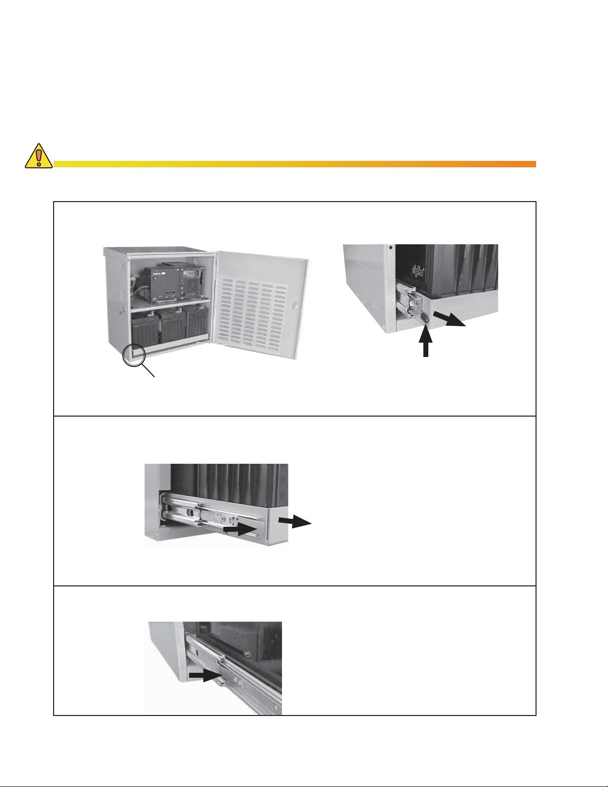
1.5 PWE Battery Tray Latch Operation (optional)
As an added safety precaution, the PWE series features a latch to hold the optional
battery slide trays securely in place, in both open and closed positions. The latch
automatically locks in place when the tray is pushed back in.
CAUTION!
The maxiumum weight of the battery slide tray is indicated by the color of the cap on the latch:
Black: max. 72lbs (32.7kg) (legacy enclosures); red: max. 82lbs (37.2kg) (standard for future enclosures).
Opening the PWE Battery Slide Tray:
2. Pull Out
PWE Tray Latch Location
Opening the PWE-4 and PWE-8 Trays:
1. Press In
Closing the Tray on all PWE models:
1. Push Up
To open, push latch up and pull tray
out. Tray automatically locks into “open”
position.
To open, press tray latch in and pull
tray out. Tray automatically locks in
the “open” position.
2. Pull Out
To unlock and close tray, press lock
in toward tray and push tray closed.
Press In
When returned to the “closed”
position, tray automatically locks
back into place.
Fig, 1-5, Opening the PWE Battery Slide Trays
031-161-B0-006, Rev. F14
Page 15
1.0 Introduction, continued
1.6 PWE Lid Removal
1. Pull Out
2. Pull Up
Fig, 1-6, PWE Lid Removal
1.7 PWE/PME Enclosure Specifi cations
Model
PWE-3
PWE-4
PWE-6
PWE-8
PWE-9
PWE-D36
PME
Dimensions
(W x H x D) (in/mm)
24.25 x 24.5 x 14/
616 x 622 x 356
30.25 x 24.75 x 16/
768 x 629 x 406
24.25 x 36.75 x 14
616 x 933 x 356
30.25 x 36.88 x 16
768 x 937 x 406
24.25 x 47 x 14
616 x 1194 x 356
24.25 x 47 x 14
616 x 1194 x 356
22.25 x 24.5 x 14
565 x 622 x 356
Shipping
Weight (lb/kg)
38/17.2 3 349/158.3
59/26.8 4 445/201.8
56/25.4 6 594/269.4
90/40.8 8 780/353.8
70/31.8 9 750/340.2
65/29.5 6 600/272.2
34/15.4 3 344/156
Battery Capacity
The lid can be completely
removed by disconnecting
retention strap
Approx. Full System
Weight (lb/kg)
Table 1-1, PME/PWE Enclosure Specifi cations
1.8 PWE Legacy Models
New PWE (Since April, 2002) Type II PWE Type I PWE
15031-161-B0-006, Rev. F
Page 16

2.0 Installation
CAUTION!
• Never transport the unit with installed batteries. Doing so can cause injury or damage to the
enclosure and installed equipment. Install the batteries after you transport the unit to the site
and secure it to the pole.
• Alpha recommends that you position the enclosure on the opposite side of the pole from traffi c.
This reduces the danger of falling equipment in the event that a pole is struck by an automobile.
• Mounting bolts must completely penetrate the wooden pole. Secure the bolts from the back with
a large washer and nut.
• System installation at >10º angle in not recommended.
ATTENTION:
The majority of poles belong to the local utility. Before you install an enclosure have both the location and
mounting method approved by the utility. Because most codes require the enclosure to be located at a
minimum height from the ground, always verify local height restrictions before you proceed.
2.1 Pole-mounting
2.1.1 Wooden Pole
Tools and Materials Required (customer supplied):
• Two (three for PWE-8, 9, D36) 5/8" (15.9mm) diameter machine bolts, length to
suit pole
• Two 5/8" (15.9mm) diameter zinc plated fl at washers
• Two 5/8" (15.9mm) diameter hex nuts (UNC thread)
• Auger or drill for boring 11/16" (17.5mm) diameter holes in the wooden pole
• Mallet or hammer
• Assorted sockets
• Tape measure
• Three-foot level
Procedure:
1. Unpack the enclosure and galvanized brackets.
2. Mark the position for the upper bracket on the utility pole. From the installation
side of the pole, and using a three-foot level to verify level, drill a 11/16"
(17.5mm) hole completely through the pole.
3. Mark the location of the hole(s) for the lower bracket(s). For three-bracket
enclosures, use the one-piece, 3-point bracket as a template. Spacing between
the holes is as follows:
Enclosure Distance (on center) (in/mm)
PWE-3 and PME 18"/457.2
PWE-4 15"/381
PWE-6 30"/762
PWE-8, PWE-9,
PWE-D36 (three holes)
4. Using the three-foot level to verify drill angle, drill the 11/16" (17.5mm) hole or
holes for the lower bracket or brackets from the installation side of the pole.
NOTE:
Drill all holes from the enclosure side of the pole to ensure proper spacing.
15" (30" total)/
381 (762 total)
031-161-B0-006, Rev. F16
Page 17

2.0 Installation, continued
2.1 Pole-mounting, continued
2.1.1 Wooden Pole, continued
5. Secure the brackets to the pole using the 5/8" (15.9mm) machine bolts, washers,
and nuts.
6. Lift the enclosure onto the brackets. It might be necessary to rock and pull the
enclosure to properly seat it on the brackets.
7. Secure the enclosure to the brackets using the 3/8" x 3/4" (9.5mm x 19mm) hex
bolts.
8. Make sure all nuts and bolts are fully tightened and the fl anges of the brackets seat
in the wood.
9. The enclosure is now ready for the utility connection, power module, and batteries.
Cable Power Out
PWE-3
Nuts & Washers
18" (457.2mm)
Nuts & Washers
5/8" (15.9mm) Bolts
Upper Mounting Bracket
Utility Power In
(with BBX)
Chassis Ground
Lower Mounting
Bracket
5/8" (15.9mm) Bolts
Upper Mounting Bracket
Lower Mounting
Bracket
PME
18" (457.2mm)
Cable Power Out
Chassis Ground
Utility Power In
Fig. 2-1, PWE/PME Series Wooden Pole Mounting
17031-161-B0-006, Rev. F
Page 18

2.0 Installation, continued
2.1 Pole-mounting, continued
2.1.2 Concrete or Steel Pole
Tools and Materials Required (customer supplied):
• Stainless steel banding (or equivalent), rated to support loaded enclosure and
sized for pole diameter
• Assorted sockets
Procedure:
1. Unpack the enclosure and galvanized brackets; turn the enclosure facedown on
a soft surface.
2. Slide a bracket up through the enclosure’s lower mounting bracket. The bracket’s
fl anges must face away from the enclosure. Secure the lower mounting bracket
using the 3/8" x 3/4" (9.5mm x 19mm) hex bolt included.
3. Position the upper mounting bracket on the pole and secure using banding.
4. Lift the enclosure onto the upper mounting bracket and pull downward to properly
seat it. Center the enclosure on the pole.
5. Secure the lower mounting bracket on the pole using banding. Spacing between
banding is as follows:
Enclosure Distance (on center) (in/mm)
PWE-3 and PME 18"/457.2
PWE-4 15"/381
PWE-6 30"/762
PWE-8, PWE-9,
PWE-D36 (three straps)
6. The enclosure is now ready for the utility connection, power module, and
batteries.
15" (30" total)/
381 (762 total)
031-161-B0-006, Rev. F18
Page 19

2.0 Installation, continued
2.1 Pole-mounting, continued
2.1.2 Concrete or Steel Poles, continued
18" (457.2mm)
18"
18" (457.2mm)
18"
Fig. 2-2, PWE/PME Series Steel or Concrete Pole-mounting
19031-161-B0-006, Rev. F
Page 20

2.0 Installation, continued
PowerMeter
Ground Wire
2.1 Pole-mounting, continued
2.1.3 Enclosure Grounding: Pole-mount
NOTE:
Alpha recommends using the grounding method illustrated below. The grounding method may vary depending
on local codes and other site-specifi c characteristics.
External Grounding Lug
#6 Bare Copper Wire
1/2" (12.7mm) X 8' (2.4m)
Copper Ground Rod
Fig. 2-3, Enclosure Grounding for Pole-mount Confi guration
(with generator backup)
031-161-B0-006, Rev. F20
Page 21

2.0 Installation, continued
2.2
Ground-mount Installation: PWE-4, PWE-8, PWE-9, PWE-D36
CAUTION!
Never transport the unit with installed batteries. Doing so can cause injury to the installer, or
damage the enclosure and equipment. Install the batteries after you transport the unit to the site
and secure it to the pad.
ATTENTION:
It is the responsibility of the installer to meet the requirements of all applicable national and local codes. Alpha
Technologies assumes no responsibility or liability for failure of the installer to comply with the requirements of
all applicable local and national codes.
2.2.1 Pre-Installation
Before choosing a location and beginning installation, consider the following:
Provide adequate room for service personnel to remove the doors for battery •
installation and removal.
Wherever possible, select a site that is above the 100-year fl ood plain and away •
from residences.
Locate in the shade to minimize the effects of solar loading.•
Locate in an area with good airfl ow.•
Locate away from sprinkler systems or other sources of forced water.•
Locate out of the prevailing wind to minimize the buildup of snow or accumulation •
of wind-borne dust.
Avoid locating the enclosure where it will be an obstruction or will inhibit visibility.•
Evaluate the soil conditions for suitability for the installation of the grounding •
system applicable to your particular installation.
Is utility power cabling run to and terminated at the site? •
NOTE:
The appropriate grounding method for a particular location depends on soil type, available space, local codes,
NEC (National Electric Code), and other site-specifi c characteristics.
21031-161-B0-006, Rev. F
Page 22

2.0 Installation, continued
2.2 Ground-mount Installation:
2.2.1 Pre-Installation, continued
Alpha Technologies, Inc. cannot anticipate all the ways a vehicle could threaten an
installed system or the specifi c type of protection that is appropriate for a particular
location. The following installation drawing for Alpha’s Standby Power systems are
general recommendations and not intended to be a specifi c guideline for protecting
the equipment. The numbers of bollard posts (or other protection devices) depend
upon equipment locations.
PWE-4, PWE-6, PWE-8, PWE-9, PWE-D36, continued
SIDEWALK
PA D
POSTS
10’ (3m)
SPRINKLER HEAD
Fig. 2-4, Ground-mount Positioning and Safety
031-161-B0-006, Rev. F22
Page 23

2.0 Installation, continued
2.2 Ground-mount Installation: PWE-4, PWE-8, PWE-9, PWE-D36, continued
2.2.2 Enclosure Grounding: Ground-mount
NOTE:
• Alpha generally recommends using the grounding method illustrated below. However, the grounding
method appropriate for a particular site depends on local codes, the NEC (National Electric Code), and
other site-specifi c characteristics.
• Alpha Technologies recommends 5 ohms minimum ground resistance between enclosure and ground
rods, in accordance with IEEE 1100-1999 Powering and Grounding Electronic Equipment.
• Alpha Technologies assumes no responsibility or liability for failure of the installer to comply with the
requirements of all applicable local and national codes. Where allowed, exothermic welding may be used
as an alternative to Burndy clamps and connectors.
CAUTION!
Corrosion-proof, twenty-fi ve-year connections suitable for direct burial must be used.
Burndy YGHP58C2W-2TN or Equivalent
Burndy YGHP58C2W-3 or Equivalent
2
8' (2.4m) Ground Rods
6’ (1.8m) Apart (min.)
2
4
1
2
Fig. 2-5, Suggested Grounding Method
#2 AWG
Terminate at Service Entrance Ground Bar
Terminate at Enclosure Ground Bar
2' (0.6m)
2' min.
min.
2
3
Service Grounding (required)
#6 bare copper wire from service entrance ground bar, with two 1/2" X 8' (12.7mm x 2.4m) copper
1
ground rods, driven at least six feet (1.8 meters) apart.
Lightning Protection (optional)
2
Four 1/2" X 8' (12.7mm x 2.4m) copper ground rods, driven at least two feet from pad.
3
#6 bare copper wire loop, at least 30" (762mm) below grade, and terminated at each ground rod.
4
#6 bare copper wire from loop to enclosure ground bar in service entrance.
23031-161-B0-006, Rev. F
Page 24

2.0 Installation, continued
2.2 Ground-mount Installation PWE-4, PWE-8, PWE-9, PWE-D36, continued
2.2.3 Ground-mount Installation, PWE-3, PWE-9 and PWE-D36
NOTE:
PWE-9 and PWE-D36 enclosures require a pedestal mount kit and Coax Raceway for ground installation.
Pedestal kit part number: 745-400-20 (gray); 745-400-21 (white). Coax Raceway part number: 604-432-B1
(gray); 604-432-C3 (white).
Tools and Materials Required (customer supplied):
• Four 1/2" (12.7mm) anchor bolts (Hilti-style recommended)
• Four 1/2" (12.7mm) stainless steel washers
• 2' X 3' (.6m x .9m) continuous vapor barrier (e.g. 30 lb. felt, neoprene pond liner,
or a heavy grade tar paper)
• Hammer drill
• 1/2" (12.7mm) drill bit
• 1/2" (12.7mm) wrench
• Metal punch
• Mallet or hammer
• Torque wrench
• Tape measure
CAUTION!
A 25+ year continuous vapor barrier must be placed between the pedestal and the pad to prevent
moisture ingress and corrosion caused by metal-to-concrete contact.
Procedure:
1. Place the vapor barrier material on concrete pad.
2. Using the pedestal as a template, mark the vapor barrier material in the locations
of the four anchor bolts holes.
3. Drill 1/2" (12.7mm) holes through the vapor barrier and into the pad at the four
marked anchor points.
4. Position the pedestal over holes and insert anchor bolts. Torque the anchor bolts
to bolt manufacturer specifi cations. If Hilti-style bolts are used, torque until head
pops.
5. On the enclosure, remove the four 3/8" (9.5mm) diameter knock-outs located
beneath the lower battery shelf.
6. Lift the enclosure onto the pedestal. Slide the lower battery tray to the fully
extended and locked position. Align the four enclosure mounting holes with the
mounting holes on the top of the pedestal. Secure the enclosure to the pedestal
using the provided 1/4" (19mm) hardware. Torque to 75 in-lbs.
7. Trim away excess vapor barrier material.
8. The enclosure is now ready for the utility connection, power module, and
batteries.
031-161-B0-006, Rev. F24
Page 25

2.0 Installation, continued
2.2 Ground-mounting PWE-4, PWE-8, PWE-9, PWE-D36, continued
2.2.3 PWE-9 and PWE-D36 Ground-mount Installation, continued
Coax Raceway
Coax Sweep
3.25"
(82.6mm)
3"
(76.2mm)
Pad
Outside of
Pedestal
3.8"
(96.5mm)
Inner Flange on Bottom of Pedestal
Pedestal Anchor Holes
Utility Sweep
Enclosure Mounting
Holes
21.38"
(543mm)
(on center)
Coax Raceway
Mounting
Pedestal Anchor
Holes
9" (228.6mm)
(on center)
Fig. 2-6, PWE-3, PWE-6, PWE-9, and PWE-D36 Enclosure Pedestal
(Not Shown)
Fig. 2-7, Location of (4) Knockouts for Enclosure-to-Pedestal Mounting
(Note: two locations are not shown in picture)
25031-161-B0-006, Rev. F
Page 26

2.0 Installation, continued
2.2 Ground-mount Installation, PWE-4, PWE-8, PWE-9, PWE-D36, continued
2.2.4 PWE-4 and PWE-8 Ground-mount Installation
NOTE:
PWE-4 and PWE-8 enclosures require a ground mount kit for ground installation. Alpha P/N 745-067-20. This
kit only fi ts enclosures manufactured after April 2002. See Fig. 2-11 to identify compatible enclosures.
Tools and Materials Required (customer supplied):
• Four 1/2" (12.7mm) anchor bolts (Hilti style recommended)
• Four 1/2" (12.7mm) stainless steel washers
• Hammer drill
• 1/2" (12.7mm) drill bit
• 1/2" (12.7mm) wrench
• Metal punch
• Mallet or hammer
• Torque wrench
• Tape measure
Procedure:
1. Turn the enclosure face down on a soft, non-abrasive surface. Remove the six
knock-outs on bottom of enclosure using a hammer and a metal punch.
CAUTION!
Metal from knockouts must be removed from the enclosure before installing batteries or electronics.
2. Secure the mounting brackets to the enclosure with the six bolts provided. Insert
the bolts from inside the enclosure. Use the holes in the battery tray to access
the front bolt locations (See Fig. 2-8). Tighten the bolts to 240 in-lbs.
3. Use the enclosure with mounting brackets installed as a template and mark the
four anchor bolt locations on the pad.
4. Drill the holes for the four anchor bolts in the pad.
5. Mount the enclosure to the pad using the 1/2" (12.7mm) anchor bolts and
washers. Torque bolts to manufacturer’s specifi cations. If Hilti style bolts are
used, torque until head pops.
6. The enclosure is now ready for the utility connection, power supply, and batteries.
Fig. 2-8, Access Holes for Front Bracket Mounting Locations
031-161-B0-006, Rev. F26
Page 27

2.0 Installation, continued
2.2 Ground-mount Installation, PWE-4, PWE-8, PWE-9, PWE-D36, continued
2.2.4 PWE-4 and PWE-8 Ground-mount Installation, continued
Fig. 2-9, Ground-mounting Brackets, Installed
Anchor Bolt Locations
27"
(685.8mm)
11"
(279.4mm)
Front of Enclosure
Fig. 2-10, Enclosure Ground-mount Footprint
NOTE:
This kit is only compatible with enclosures manufactured after April 2002.
Array of Louvers
Covering Front Door
No louvers
on sides
Compatible Enclosures Incompatible Enclosures
Fig. 2-11, Enclosures Manufactured Before and After April 2002.
27031-161-B0-006, Rev. F
Page 28

2.0 Installation, continued
2.3 Connecting Utility Power
WARNING!
ONLY qualifi ed personal should connect the utility power. Power must be connected in
compliance with local electrical codes, and common safety practices must be observed.
ATTENTION:
• Connection to utility power must be approved by the local utility before installing the power supply.
• UL and NEC require that a service disconnect switch (UL listed) be provided by the installer and be
connected between the power source and the Alpha power supply.
• Connection to the power supply must include an appropriate service entrance weather head.
Utility power enters the enclosures through a 1-1/8" (28.6mm) opening in the bottom of the
PME series, and in the rear of the PWE series, or through an optional breaker box. The
enclosures accept a standard electrical fi tting.
A “high-magnetic” trip circuit breaker must be used in order to accommodate the high-inrush
currents normally associated with the start-up of ferroresonant transformers (400A, no-trip,
fi rst-half cycle). Do not replace this circuit breaker with a conventional service entrance circuit
breaker. Alpha recommends Square D circuit breakers for 120V installations, and HACR
(heating and air-conditioning) breakers for 240V installations. Alpha Technologies offers a
high-magnetic Square D circuit breaker and a BBX option (a UL Listed service entrance).
Contact your local sales representative for more information.
Description Alpha Part Number Square D Part Number
240V Installation — HACR (15A) 470-224-10 QO215
120V Installation — High-Magnetic (20A) 470-017-10 QO120HM
120V Installation — High-Magnetic (15A) 470-013-10 QO115HM
BBX — External Service Disconnect 020-085-10 QO2-4L70RB
BBX — External Service Disconnect 020-141-10 QO8-16L100RB
Table 2-1, Service Entrance Circuit Breaker Requirements
NOTE:
Alpha recommends 12AWG wiring to accommodate a 90V power supply.
031-161-B0-006, Rev. F28
Page 29

2.0 Installation, continued
2.3 Connecting Utility Power, continued
In most cases, the following confi gurations qualify for service entrance use. However,
confl icting codes may apply. Always contact your local utility to verify that the wiring conforms
to applicable codes.
240Vac Service
(XM2-915 240 Power
Supply; XM Series 2 922-48
for PWE-4 and PWE-8)
120Vac 20A Service
(XM2-915 120 Power
Supply)
120Vac 15A Service
(XM2-615 120 Power
Supply)
Enclosures used with the XM Series 2, model 915-240 or
922-48, are equipped with a 240Vac duplex receptacle to
provide power to the power supply and peripheral equipment.
This NEMA 6-15R receptacle is protected by a 2-pole, common-trip, 15A circuit breaker located inside the service entrance. Wiring is typically 14AWG, per NEC code. A grounding clamp is located on the enclosure facilitates dedicated
grounding.
Enclosures used with the XM Series 2, model 915-120, are
equipped with a 120Vac duplex receptacle to provide power
to the power supply and peripheral equipment. This NEMA
5-20R receptacle is protected by a 2-pole, common-trip, 20A
circuit breaker located inside the service entrance. Wiring is
typically 12AWG, per NEC code. A grounding clamp is located
on the enclosure facilitates dedicated grounding.
Enclosures used with the XM Series 2, model 615, are
equipped with a 120Vac duplex receptacle to provide power
to the power supply and peripheral equipment. This NEMA
5-15R receptacle is protected by a single-pole, 15A, HighMagnetic circuit breaker located inside the service entrance.
Wiring is typically 14AWG, per NEC code. A grounding clamp
is located on the enclosure facilitates dedicated grounding.
29031-161-B0-006, Rev. F
Page 30

2.0 Installation, continued
2.3 Connecting Utility Power, continued
L1 (Black)
Copper Ground
Wire #8 AWG min.
Breaker
Grounding Point Made
to Enclosure Wall
L1 (Black)
120Vac
To Utility
Neutral (White)
Neutral Bus
Grounding Point Made
To Enclosure
Receptacle
L2 (Red)
Copper Ground
Wire #8 AWG min.
Breaker
to Enclosure Wall
L1
L2
Fig. 2-12, Typical Service Entrance Wiring
120Vac 15A Receptacle, 5-15R 120Vac 20A Receptacle, 5-20R
Neutral
(White)
L1
(Black)
Neutral
(White)
240Vac
L1
(Black)
To Utility
L1 (Black)
Neutral (White)
Neutral Bus
To Enclosure
Receptacle
Ground
(Green)
240Vac 15A Receptacle, 6-15R
L2
(Red)
L1
(Black)
Ground
(Green)
Fig. 2-13, Typical Receptacle Wiring
Ground
(Green)
031-161-B0-006, Rev. F30
Page 31

2.0 Installation, continued
2.3 Connecting Utility Power, continued
Ground
Line 2
Line 1
ON
Neutral
Ground
Line
ON
OFF
OFF
ISE 240V 15A
ISE 120V 20 A
Neutral
Ground
Line
ON
ISE 120V 15A
OFF
Fig. 2-14, Typical ISE (Internal Service Entrance) Receptacle Wiring
31031-161-B0-006, Rev. F
Page 32

2.0 Installation, continued
2.3 Connecting the Utility Power, continued
Ground
Line 2
Line 1
Neutral
Ground
Line 2
Line 1
Neutral
Ground
Line
ON
OFF
ON
OFF
BQO 240V, 15A BQO 120V, 20A
Neutral
Ground
Line
OFF
ON
BQO 240V, 120V
ON
OFF
ON
OFF
BQO 120V, 20A Dual
Receptacle, Dual Breaker
Fig. 2-15, Typical BQO (Breaker Quad Option) Receptacle Wiring
031-161-B0-006, Rev. F32
Page 33

2.0 Installation, continued
2.3 Connecting the Utility Power, continued
Service Drop
Cable Output
External Grounding Lug
Utility Power Input
5.5'
5' 6"
(1.7m)
Meter
Service Entrance
Fig. 2-16, PWE Pole-mount Confi guration
NOTE:
Alpha offers a Meter Convenience Assembly (MCA) as a cost-effective alternative to building
an assembly on-site. The MCA is a factory-confi gured, pole-mount meter and service
disconnect with integral bracket that makes installation simple and consistent.
Product Description Part Number
FBX (20A fuse kit included) 745-126-20
100A BBX 745-126-21
70A BBX 745-126-22
Alternate Meter (e.g. Universal Meter Base) Contact Alpha Representative
33031-161-B0-006, Rev. F
Page 34

2.0 Installation, continued
2.3 Connecting Utility Power, continued
Line 1
Neutral
Meter Socket Clamp
Ground
Line 2
Fig. 2-17, Meter Wiring
Line 1
Ground Bus
Circuit Breaker
(Square D Q0220)
Ground
Neutral
Line 1
Fig. 2-18, 240Vac CSA Service Entrance Wiring
Line 2
Neutral
ON
20
OFF
Neutral Bus
Line 2
Ground Clamp
#8 AWG (Min.) Copper Ground Wire
Line 1
Circuit Breaker
(Square D Q0220)
Ground
Neutral
Ground
Line 1
Fig. 2-19, 240Vac UL Service Entrance Wiring
Line 2
Neutral
ON
20
OFF
Neutral Bus
Line 2
Ground Clamp
#8 AWG (Min.) Copper Ground Wire
031-161-B0-006, Rev. F34
Page 35

2.0 Installation, continued
2.4 Connecting the Coaxial Cable
2.4.1 Coaxial Cable Surge Protector Installation Instructions
Alpha recommends using coaxial surge suppression for enclosure protection. The
Coax Surge Protector with Ground Block (Alpha P/N 745-910-21) includes 75 ohm
surge suppressor, mounting hardware, and waterproofi ng grommet.
Required Tools:
• Drill with 3/16" (4.8mm) bit. For older enclosures a 3/4" (19mm) bit is also
needed.
• Phillips screwdriver
• 3/8" (9.5mm) socket and driver
1. Drill two 3/16" (4.8mm) holes 1½" (38.1mm) apart (indicated locations are
recommended). Newer enclosures have center punch marks on the left and right
side of the enclosure.
2. Attach the surge protector to the inside of the enclosure wall with provided
hardware. For proper grounding, ensure the included star washers come in
contact with the enclosure wall.
3. On newer enclosures, knock out one of the 3/4" (19mm) knockouts located in
the upper rear of the enclosure. On older enclosures, drill a 3/4" (19mm) hole
in desired location. Press the grommet into the hole from the outside of the
enclosure.
4. Cut center of grommet and insert coaxial cable.
6.5" to 7.25"
(165.1mm to 184.2mm)
5. Pull cable back to form seal.
3/4" (19mm)
Knockouts
(for grommet)
remotsuCecivreS
SERVICE
CUSTOMER
Grommet Installation
4"
(101.6mm)
1.5"
(38.1mm)
¾"
Cut center
35031-161-B0-006, Rev. F
Page 36

2.0 Installation, continued
2.4 Connecting the Coaxial Cable, continued
2.4.2 Connecting the Service Power Inserter (SPI)
WARNING!
Disconnect all power sources from the SPI (Service Power Inserter) before removing its
cover. Verify that the SPI is disconnected from both the utility power and the power supply
before beginning procedure.
PWE Enclosures
Power Suppy Output
(Coaxial Cable)
SPI
PME Enclosures
Fig. 2-20, SPI Locations
Procedure:
1. Disconnect the SPI from all power sources.
2. Remove the two screws securing the cover to the SPI chassis.
Remove the cover, exposing the circuit board and seizure
screw assembly.
Seizure Screw
Output Port
SPI
Power Suppy Output
(Coaxial Cable)
Stinger
Seizure Screw
Assembly
Coaxial
Termination
SPI Cover
Fig. 2-21, SPI Fig. 2-22, SPI (side view)
3. Screw the Coaxial Termination into Output Port on bottom of SPI, inserting the stinger
into the seizure screw assembly.
4. Tighten seizure screw to 35 in-lbs.
CAUTION!
To prevent arcing and failure of the unit, insert the coaxial cable completely into the seizure screw
assembly and tightened the seizure screw to 35 inch-pounds.
5. Replace SPI cover and reinstall screws.
6. Verify switch on top of SPI is on the ON position.
031-161-B0-006, Rev. F36
Page 37

2.0 Installation, continued
2.5 Battery Installation
2.5.1 Battery Date Code Usage and Identifi cation
Every battery contains a DATE CODE. This code is usually located near the positive
(+) terminal, and must be recorded in the maintenance log. If you use batteries other
than those installed by Alpha, consult the batteries’ manufacturer’s documentation for
date code type and placement.
NOTE:
The date code scheme and location varies depending on the age of the battery used.
Month: June
Fig. 2-23, Battery Date Code
Year: 2005
37031-161-B0-006, Rev. F
Page 38

2.0 Installation, continued
2.5 Battery Installation, continued
2.5.2 Battery Installation Procedure
WARNING!
To prevent arcing, never allow live battery cables to make contact with the enclosure.
Disconnect battery leads, or wrap the cable lugs with electrical tape.
CAUTION!
Threaded insert terminals require the use of 3/4" (19mm) bolts. The use of 1" (25.4mm) bolts will
seriously damage the battery. The only exception is the terminal with the large spacer for the in-line
fuse link. See section 2.5.5 for details.
NOTE:
In battery confi gurations made up of multiple battery strings, Alpha strongly recommends the use of in-line
fuses.
Procedure:
1. Place the batteries on the enclosure’s battery slide tray or battery shelf. The
correct arrangement of the batteries on the tray or shelves varies between
enclosure models. See the Figs. 2-26 through 2-31 for the correct battery
arrangement for each model. Leave a minimum of one inch of ventilation space
between the batteries.
2. To make identifi cation and record keeping easier, number and label the batteries.
Record each battery’s number and date code in the power supply maintenance
log.
3. Using the battery arrangement diagrams as a reference, connect the batteries
in series to achieve 36Vdc or 48Vdc. Refer to the diagrams for the location
of the optional in-line fuses. Torque terminal connections according to battery
recommendations (see battery label for AlphaCell batteries).
4. Check the polarity and voltage of the battery cable connector with a voltmeter
to verify correct connections. Do Not connect the battery string or strings to the
power supply at this time.
5. The power supply battery charger collects battery temperature compensation
information with a Remote Temperature Sensor (RTS) attached to one of the
batteries. Refer to the diagrams to determine which battery to attach the RTS
to. Attach the RTS about 1/3 of the way up from the battery’s base with a strong
adhesive tape. Route the RTS connector into the power supply compartment. Do
Not connect the RTS to the power supply at this time.
CAUTION!
Recheck the polarity and voltage of the battery cable connector before proceeding. Connecting
the battery string or strings to the power supply with incorrect polarity will cause a short-circuit, and
possible equipment damage.
6. Route the battery cable connector into the power supply compartment. Do Not
connect to the batteries to the power supply at this time.
031-161-B0-006, Rev. F38
Page 39

2.0 Installation, continued
2.5 Battery Installation, continued
2.5.3 Connecting the Battery Integration Tray (PWE 3/6 Only)
1. Connect the battery cable kits (Alpha P/N 875-690-20) to each battery, and to
matching connector on the Battery Integration Tray (BIT). Torque to the battery
manufacturer's specifi cation (for AlphaCell batteries see battery label).
2. If applicable, secure the batteries with the optional Battery Retaining Bar (BRB)
(Alpha P/N 744-346-20). The BRB mounts in factory installed spring clips.
External Generator
Connector
Individual Battery
Connectors
(3 per tray)
Power Supply Connection
Battery Retaining Bar
External Generator
Connection Cabling
Prewired AlphaGuard
Shelf
Battery Retaining Bar
Fig. 2-24, Battery Integration Tray Connections
39031-161-B0-006, Rev. F
Page 40

2.0 Installation, continued
2.5 Battery Installation, continued
2.5.4 Battery Terminal Connections
NOTE:
• Various types of batteries with different mounting styles and hardware may be shipped with the system.
ALWAYS refer to the battery manufacturer’s specifi cations for correct mounting hardware and torque
requirements. Use only the hardware and torque recommended by the battery manufacturer.
• There are two types of battery terminals: the newer, threaded insert terminals, and the older, fl ag
terminals. The following drawings and pictures are for illustrative purposes only.
Threaded Insert Terminals
CAUTION!
Threaded insert terminals require the use of 3/4" (19mm) bolts. The use of 1" (25.4mm)
bolts will seriously damage the battery. The only exception is the terminal with the large
spacer for the in-line fuse link.
3/4" (19mm) x 1/4-20 Bolt
Split Washer
Flat Washer
Battery Sense Cable
Battery Cable
Battery Terminal
Nut
Split Washer
Flat Washer
Battery Cable
In-Line Fuse Link
Flat Washer
1" (25.4mm) or 3/4" (19mm) x 1/4-20 Bolt
1" (25.4mm) x 1/4-20 Bolt
Split Washer
Flat Washer
Fuse
Spacer
Battery Terminal
Fig. 2-25, Threaded Insert Battery Terminal Connections
031-161-B0-006, Rev. F40
Page 41

2.0 Installation, continued
2.5 Battery Installation, continued
2.5.4 Battery Terminal Connections, continued
Flag Terminals
Battery Sense Cable
Flat Washer
Split Washer
Nut
Battery Cable
Battery Terminal
Nut
Split Washer
Flat Washer
Battery Cable
In-Line Fuse Link
Flat Washer
1" (25.4mm) or 3/4" (4.8mm) x 1/4-20 Bolt
Flat Washer
1" x 1/4-20 Bolt
1" (25.4mm) x 1/4-20 Bolt
Split Washer
Flat Washer
Spacer
Fig. 2-26, Flag Battery Terminal Connections
Battery Terminal
41031-161-B0-006, Rev. F
Page 42

2.0 Installation, continued
2.5 Battery Installation, continued
2.5.5 Battery Wiring Diagrams
Battery Cable Connector
(to XM2 Power Supply)
R E D (+)
B L A C K (-)
Black (-)
Red (+)
Temperature Probe
(Connected to XM2)
RTS
(Taped to side of battery)
Battery Cable Connector
(to XM2 Power Supply)
Red (+)
3
Fig. 2-27, PWE-3 (without BIT) and PME Battery Wiring Diagram
R E D (+)
B L A C K (-)
Black (-)
2
Temperature Probe
(Connected to XM2)
1
In-line Fuse (optional)
RTS
(Taped to side of battery)
3
4
Fig. 2-28, PWE-4 Battery Wiring Diagram
1
2
In-line Fuse
(optional)
031-161-B0-006, Rev. F42
Page 43

2.0 Installation, continued
R E D (+)
B L A C K (-)
2.5 Battery Installation, continued
2.5.5 Battery Wiring Diagrams, continued
CAUTION!
If using the optional slide tray, zip-tie the negative black wire to the center battery interconnection
cable. This will prevent the wire interfering with slide tray closure.
Battery Cable Connector
(to XM2 Power Supply)
Temperature Probe
(Connected to XM2)
R E D (+)
B L A C K (-)
Red (+)
Black (-)
Zip-tie together
Upper Tray
Zip-tie to
enclosure fl ange
Lower Tray
3A
3B
2A
2B
1A
1B
RTS
(Taped to side of battery)
In-line Fuse (optional)
Zip-tie to
enclosure fl ange
In-line Fuse (optional)
Fig. 2-29, PWE-6 Battery Wiring Diagram (without BIT)
43031-161-B0-006, Rev. F
Page 44

1A
2A
3A
1B
2B
3B
R E D (+)
B L A C K (-)
R E D (+)
B L A C K (-)
2.0 Installation, continued
2.5 Battery Installation, continued
2.5.5 Battery Wiring Diagrams, continued
Battery Cable Connectors
(to XM2 Power Supplies)
Black (-)
Red (+)
Upper Tray
Temperature Probe
(Connected to XM2)
Lower Tray
Red (+)
Black (-)
RTS
(Taped to side
of battery)
In-line Fuse
(optional)
RTS
(Taped to side
of battery)
Fig. 2-30 PWE-D36 Battery Wiring Diagram
In-line Fuse
(optional)
031-161-B0-006, Rev. F44
Page 45

2.0 Installation, continued
2.5 Battery Installation, continued
2.5.5 Battery Wiring Diagrams, continued
Battery Cable Connector
(to XM2 Power Supply)
R E D (+)
B L A C K (-)
Temperature Probe
(Connected to XM2)
RTS
(Taped to side of battery)
Red (+)
Upper Tray
Black (-)
3A
4A
3B
1A
2A
In-line Fuse
(optional)
1B
Lower Tray
4B
2B
Fig. 2-31, PWE-8 Battery Wiring Diagram
In-line Fuse
(optional)
45031-161-B0-006, Rev. F
Page 46

2.0 Installation, continued
2.5 Battery Installation, continued
2.5.5 Battery Wiring Diagrams, continued
Battery Cable Connector
(to XM2 Power Supply)
R E D (+)
B L A C K (-)
Red (+)
Black (-)
Temperature Probe
(Connected to XM2)
In-line Fuse (optional)
Upper Tray
Middle Tray
3A
3B
2A
2B
1A
RTS
(Taped to side of battery)
In-line Fuse
(optional)
1B
In-line Fuse
(optional)
Lower Tray
3C
Fig. 2-32, PWE-9 Battery Wiring Diagram
2C
1C
In-line Fuse
(optional)
031-161-B0-006, Rev. F46
Page 47

2.0 Installation, continued
OUTPUT 2
OUTPUT 1ALRI
Battery
Input
Temp
Probe
Battery
Breaker
OUTPUT 1B
N+1
N+1
2.6 Installing the XM Series 2 Power Supply
Installation Procedure:
1. Before installation, inspect the power supply for damage or loose connectors.
2. Place the XM Series 2 Power Supply in the lower-right compartment of PME enclosures,
or the upper-right compartment of PWE enclosures.
3. Switch the BATTERY BREAKER on the front of the power supply OFF. This prevents the
inverter from starting when the batteries are fi rst connected to the power supply. See Fig.
2-32.
CAUTION!
Check the polarity and voltage of the battery cable connector with a voltmeter before proceeding.
Connecting the battery string or strings to the power supply with incorrect polarity may cause a
short-circuit, and possible equipment damage. Check all battery connections for proper installation.
For complete battery installation procedures, see the “Battery Installation” section in this manual.
4. After verifying that the batteries, battery connections, and battery cables are connected
properly, plug the battery cable connector from the battery string or BIT into the power
supply’s BATTERY INPUT connector. The connector is keyed and color-coded to fi t in
only one direction. See Fig. 2-32.
5. Plug the Remote Temperature Sensor into the TEMP PROBE connector located on the
Inverter Module assembly on the front of the power supply. See Fig. 2-32.
6. If applicable, plug the optional Local/Remote Indicator lamp (LRI) cable into the LRI
connector. See Fig. 2-32.
7. If you are installing a Tamper Switch (TMPR SW), plug it into the 2-pin TMPR connector,
and plug the transponder cable into the transponder TMPR connection. See Fig. 2-32.
8. Plug the connector from the SPI into the power supply’s OUTPUT 1A. If the enclosure
has the optional AC Indicator (ACI) lamp, plug the connector from the SPI into the ACI
and the connector from the lamp into the power supply’s OUTPUT 1A. If the PIM option is
installed, connect a second SPI to OUTPUT 2. Make sure that the SPIs “ALT/ON” switch
is in the ON position. See Fig. 2-32.
9. If the installation includes a Module Retaining Cable option, attach the end of the cable to
the hole provided at the top, rear, center of the enclosure. Thread the cable through the
power supply handle and clip it back on itself.
10. The installation is complete. Do Not apply AC power to the power supply or switch
the Inverter Module’s BATTERY BREAKER ON. Refer to the power supply Operator’s
Manual for Start-up and Test procedures.
7
83
6
Fig. 2-33, XM Series 2 Power Supply
4
5
47031-161-B0-006, Rev. F
Page 48

2.0 Installation, continued
2.7 Cooling Fan Installation
NOTE:
• This procedure requires a service power supply (for example, an APP 9015S or APP 9022S) to maintain
power to the cable plant while fan is being installed.
• The fan kit for PWE-3, 4, 6, and 8 enclosures includes a fan assembly with a single fan. The PWE-9
and PWE-D36 enclosures’ kit includes a double fan assembly. The installation and wiring procedures,
however, are identical.
Tools Required:
• Phillips Screwdriver
Installation Procedure:
1. Attach the fan assembly to the two pre-drilled holes located in the upper, right, rear of
the enclosure using the two #6-32 x 3/8" (9.5mm) Phillips screws provided. Make sure
to orient the fan assembly so that the exposed fan is up and the fan guard is down, as
shown. Screw the screws in from the outside of the enclosure.
2. Plug one end of the fan’s Y cable into the SPI wire. Plug other end of the Y cable into the
power supply’s OUTPUT 1A.
3. Position thermostat away from power supply, as shown.
1
3
2
2
Fig. 2-34, Cooling Fan Kit Installed
NOTE:
This kit fi ts only PWE Series enclosures manufactured after April 2002.
Array of louvers covering
front door
No louvers on
sides
1
Incompatible EnclosuresCompatible Enclosures
031-161-B0-006, Rev. F48
Page 49

2.0 Installation, continued
2.8 PWE-8 Solar Shield Installation
Tools Required:
• Drill
• 3/16" (4.8mm) or #12 drill bit
• Phillips screwdriver
CAUTION!
Drill only in the fi ve locations indicated below. Center punches marked with a “ ” (6 places) below
are reserved for the storm hood kit.
Installation Procedure:
1
1. Drill 3/16" (4.8mm) through-holes in the door at
the locations shown (5 places).
2. Install the solar shield to the door, using the
screws provided: #8-32 x 3/8" (9.5mm) with
square cone washer.
3. Drill 3/16" (4.8mm) through-holes in the sides of
the enclosure in the locations shown (7 places
total).
Drill Here.
4. Install the small shield on the left side and
the large shield on the right using the screws
provided.
43
Drill In
Three Places
Drill In
Four Places
NOTE:
This kit fi ts only PWE-8 enclosures manufactured after April 2002.
Array of louvers covering
front door
No louvers on
sides
2
Fig. 2-35, PWE-8 Solar Shield Installation
Incompatible EnclosuresCompatible Enclosures
49031-161-B0-006, Rev. F
Page 50

2.0 Installation, continued
2.9 Status Monitoring Transponder Bracket Installation Instructions
Tools and Materials Required:
• #10-32 nuts and fl at washers
• 3/8" (9.5mm) socket wrench or nut driver
Installation Procedure:
1. Position status monitoring bracket over status monitor, and align bracket slots with PEM
studs (located on enclosure).
Status Monitoring
Transponder
Status Monitoring
Bracket
Bracket
Slots
2. After bracket and status monitor are in position, apply fl at washers and #10-32 nuts to
PEM studs. Tighten using 3/8” (9.5mm) socket wrench or nut driver.
Fig. 2-36, Status Monitoring Bracket Location in PWE Series Enclosure
031-161-B0-006, Rev. F50
Page 51

3.0 Pole-mount Enclosure Maintenance
Preventive Maintenance should be performed every three to six months.
Inspect the Pole-mount Enclosure
Perform a complete inspection of the Pole-mount Enclosure. Look for signs of rust and corrosion,
paying particular attention to the battery trays. Clean any rust or corrosion immediately.
Inspect the Mounting Brackets and Hardware
Carefully inspect the mounting bracket and mounting hardware. Look for signs of unusual wear and
loose hardware. Correct all mounting hardware failures immediately.
Check Battery Terminals and Connecting Wires
Care of the batteries is a critical step in any maintenance program. In addition to voltage checks,
visually inspect the batteries for signs of cracking, leaking, or swelling. To aid in quick identifi cation,
and tracking of voltages in the maintenance log, number the batteries inside the enclosure using
labels or masking tape. Batteries are temperature sensitive and susceptible to overcharging and
undercharging. Since batteries behave differently in the winter than in the summer, Alpha’s battery
chargers automatically compensate for changes in temperature by adjusting fl oat and accept charge
voltages. See the power supply's technical manual for complete preventive maintenance instructions.
Check each battery terminal and connection. Verify the posts are clean and the crimped connectors
are tight. Torque terminal connections to the manufacturer's recommendation. If there is an inline fuse
in the battery cable, check the fuse holder and fuse. Verify the terminals are properly protected with
an approved battery terminal corrosion inhibitor such as NCP-2. Record date of maintenance in the
maintenance log.
Check Battery Open Circuit Voltage
Switch the power supply’s BATTERY BREAKER to the OFF position. Disconnect the battery
connector from the Inverter Module and measure the individual voltage across each battery. The
difference between any battery in the string must not be greater than 0.3Vdc. Defective or marginal
batteries must be replaced with an identical type of battery. Record the unloaded battery voltages in
the maintenance log.
NOTE:
When the power supply’s BATTERY BREAKER is turned OFF, or the batteries are not connected, backup
power is not available.
51031-161-B0-006, Rev. F
Page 52

Page 53

Alpha Technologies
Power
®
Alpha Technologies
3767 Alpha Way
Bellingham, WA 98226
USA
Tel: +1 360 647 2360
Fax: +1 360 671 4936
Web: www.alpha.com
Alpha Technologies Ltd.
4084 McConnell Court
Burnaby, BC, V5A 3N7
CANADA
Tel: +1 604 430 1476
Fax: +1 604 430 8908
Alpha Technologies
Europe Ltd.
Twyford House
Thorley
Bishop's Stortford
Hertfordshire
CM22 7PA
UNITED KINGDOM
Tel: +44 0 1279 501110
Fax: +44 0 1279 659870
Alpha Technologies GmbH
Hansastrasse 8
D 91126 Schwabach
GERMANY
Tel: +49 9122 79889 0
Fax: +49 9122 79889 21
Alphatec, Ltd
P.O. Box 56468
Limassol, Cyprus
CYPRUS
Tel: +357 25 375675
Fax: +357 25 359595
AlphaTEK ooo
Khokhlovskiy Pereulok 16
Stroenie 1, Offi ce 403
109028 Moscow
RUSSIA
Tel: +7 495 916 1854
Fax: +7 495 916 1349
Alphatec Baltics
S. Konarskio G. 48
2009 Vilnius
LITHUANIA
Tel: +370 5 213 8822
Fax: +370 5 213 7799
Alpha Technologies
9, Impasse Sans Souci
92140 Clamart France
FRANCE
Tel: +33 141 900 707
Fax: +33 141 909 312
Copyright © 2009 Alpha Technologies, Inc. All rights reserved. Alpha is a registered trademark of Alpha Technologies. 031-161-B0-006, Rev. F.
Due to continuing product improvements, Alpha reserves the right to change specifi cations without notice.
 Loading...