

Page 1

IL499
Installation Instructions for PK502B
Dual Entrance Control Unit
APPLICATION
The TekT one® PK502B Dual Entrance Control Unit provides
a means to connect T ekT one® Apartment Intercom amplifiers
to more than one entrance. Voice and door release functions
are automatically transferred to the calling entrance. The
quantity of PK502Bs needed is equal to one less than the
number of entrances.
PROCEDURE
Warning: This switching unit will not function unless
programmed for use—see Test Step #1.
1. Determine equipment location.
2. Install wiring.
3. Install equipment.
4. Check wiring and make connections.
5. Apply power and check operation.
EQUIPMENT LOCATION
Locate the PK502B within 3' (1 m) of the intercom
amplifier. If more than one PK502B is used, install them
all in the same area. Keep the PK502B away from direct
heat or extreme cold. Operating temperature should be
between 10°F and 90°F.
WIRING
1 . The first PK502B will support two entrances; each addi-
tional PK502B will support one additional entrance. For
example, a three-entrance system will have two PK502Bs.
See Figure 2 for an example with additional entrances.
2 . Wire the suite station common wires to the amplifier, and
wire the power transformer according to instructions
supplied with the amplifier.
3 . If more than one PK502B is used, run 1 cond. #18 plus 7
cond. #22 between PK502Bs. Run 3 cond. #18 plus 3 cond.
#22 from the last PK502B to the amplifier.
4 . Run 2 cond. #22 twisted shielded (2 cond. #22, plus 2 cond.
#22 shielded for PK205 amplifiers) from each entrance
panel to the associated PK502B.
5. Run multi-cond. #22 cable (use 1 cond. per suite
station) from entrance panel to entrance panel, and from
Section A
Rev. 17 - 12/2007
one entrance panel to the suite stations, as required by
instructions supplied with amplifier.
6 . From each entrance door release, run 1 cond. #18 to the
PK502B and 1 cond. #18 to the amplifier.
7. If a Post Office (P.O.) lock adapter is used, run 1 cond.
#18 to the amplifier, and 1 cond. #18 to the associated
door release from the P.O. lock adapter. In the wiring
diagram, the P.O. lock adapter is shown connected to
door release #1, but it may be connected to whichever
door release is required.
CONNECTIONS
1. Make connections as shown on the wiring diagram for
the amplifier being used. (For PK543/A amplifier, refer to
Figures 1, 2 and 3. For PK205 amplifier, refer to Figures
4 and 5.) If more than two PK502Bs are used, break the
connections going from the PK502Bs outside the dashed
lines to the amplifier and insert the wiring shown inside the
dashed lines for any additional PK502Bs.
2 . If a P.O. lock adapter is used, do not connect it until a P.O.
lock is obtained from the post office. When ready, make
connections as shown on the appropriate wiring diagram.
3 . Connect transformer to power source and follow the test
procedures in the next section.
TEST
After performing the test required in the amplifier’s
instructions, do the following:
1. The PK502B must be programmed to operate with the
amplifier being used. Locate the programming switch and
set switches as follows.
To use a PK543/A or PK205 amplifier, set switches 2 and
4 on and switches 1, 3 and 5 off. Failure to set the
programming switches properly will result in faulty operation, but will not cause permanent damage to the PK502B.
2 . Perform tests required in the amplifier’s instructions, then
at each entrance, press a call button and observe the
following:
a. The buzz tone should be heard at the called suite
station.
ALPHA COMMUNICATIONS
Toll-Free Technical Line: 1-800-666-4800 • Phone: (631) 777-5500 • Fax: (631) 777-5599
Website: www.alpha-comm.com • Email: info@alpha-comm.com
®
• 42 Central Drive • Farmingdale, NY 11735-1202
Page 2
b. If the Entrance Tone is enabled at the amplifier, then
the buzz tone should be heard at the entrance panel.
No door release:
Check wiring to terminals D0, D1 and D2.
c. Voice communication should be possible with the
called suite station.
d. If the door button is pressed at the suite station, the
door release should operate. When the door release
time has passed, the PK502B’s red test light should be
off.
3. If the P.O. lock adapter is installed, it may be tested by
using a postal service key, or by operating the P.O. lock
adapter micro switch if a key is unavailable. The door
time delay on the amplifier does not affect the P.O. lock
adapter.
TROUBLESHOOTING
If the system fails to operate properly, check all wiring. If the
wiring is correct, check the troubleshooting points on the
amplifier installation instructions. Then check the following:
No buzz:
Check wiring to terminal Z1 and Z2. If more than one
PK502B is used, then the entrance #2 buzz wire must
connect to all PK502B’s.
No voice communication:
Check wiring to terminals S0, S1, S2, M0, M1 and M2.
The PK502B has a built-in test circuit. This step should
normally be unnecessary, but to test the PK502B do the
following:
1 . Set all programming switches off.
2. The red test light, located behind the wiring connector,
should be off. If it is on, wait 3 minutes for time out, and
it should be off.
3. Set programming switch #1 on. The red test light should
be on.
4. Set programming switch #2 on. The red test light should
be off. In a quiet location, a click may be heard as the
internal relay operates.
5. Set all programming switches off. The red test light
should remain on for about 2 minutes. It is not necessary
to wait for it to go off unless busy light trouble is
encountered.
6. Reset programming switches to the desired amplifier
setting as shown in step 1 of the Test Section. Failure to
set the programming switches properly will result in
faulty operation.
If the test circuit fails this procedure, replace the PK502B.
Figure 1—PK502B Wiring Diagram for the PK543/A and 2 Entrances
#22 TWISTED PAIR SHIELDED CABLE
CONNECT SHIELD TO TERM G AT
ENTRANCE PANEL
SPEAKER
PUSHBUTTONS
(Z2)
DOOR
RELEASE
(D2)
(K)
NOTES:
1. USE #22 WIRE UNLESS SHOWN OTHERWISE.
THE AMPLIFIER. THE AMPLIFIER.
(G)
(S2)
TERMINALS
#18
TO
REMOTE
STATION
X
ENTRANCE PANEL
PUSHBUTTONS
SPEAKER
(Z1)
DOOR
RELEASE
(G)
(S1)
#22 TWISTED PAIR SHIELDED CABLE
CONNECT SHIELD TO TERM G AT
PK502B
TRANSFER RELAY
D1
BLUE / WHITE
D2
GREEN / WHITE
D0
YELLOW / WHITE
S1
ORANGE / WHITE
S2
RED / WHITE
S0
BROWN / WHITE
M1
WHITE
M2
BLACK
M0
GREY
Y1
BROWN
Y2
VIOLET
R
BLUE
Z1
GREEN
Z2
YELLOW
C
(D1)
(K)
#18
K
ORANGE
RED
PK543(A)
AMPLIFIER
L-
#18
IL499 PK502B PK543(A) TWO ENTRANCE REV1 060204 1
YELLOW
L+
YELLOW/BLACK
BROWN
D
RED
K
ORANGE
C
V
G
ORANGE/BLACK
A
BLACK
E
WHITE
5
GREEN
GREY
3
VIOLET
2
BLUE
1
RED/WHITE
ZW
BROWN/WHITE
Z
#18
P.O.LOCK
ADAPTER
16 VOLT
TRANSFORMER
#18
CONNECT TO
117 VAC
Page 2 • IL499 PK502B Installation Instructions
Copyright © TekTone Sound & Signal Mfg., Inc. All Rights Reserved.
Page 3

Figure 2—PK502B Wiring Diagram for the PK543/A and 3 to 8 Entrances
#22 TWISTED PAIR SHIELDED CABLE
CONNECT SHIELD TO TERM. G
ENTRANCE PANEL
SPEAKER
PUSH BUTTONS
(Z2)
(D2)
DOOR
E
S
A
E
L
E
R
(K)
NOTES:
1. USE #22 WIRE UNLESS SHOWN OTHERWISE.
AT THE AMPLIFIER.
(G)
ENTRANCE PANEL
SPEAKER
PUSH BUTTONS
DOOR
RELEASE
#22 TWISTED PAIR SHIELDED CABLE
CONNECT SHIELD TO TERM. G
(G) (G)
(Z1) (Z2)
(D1)
(K)
AT THE AMPLIFIER.
TO REMOTE STATION
X TERMINALS
PK502B
TRANSFER RELAY
BLUE/WHITE
D1
GREEN WHITE
D2
YELLOW/WHITE
D0
ORANGE/WHITE
S1
RED/WHITE
S2
BROWN/WHITE
S0
WHITE
M1
BLACK
M2
GREY
M0
BROWN
Y1
VIOLET
Y2
BLUE
R
GREEN
Z1
YELLOW
Z2
ORANGE
C
RED
K
REPEAT THIS SECTION TO ADD MORE ENTRANCES (SEE INSTRUCTIONS).
ENTRANCE PANEL
SPEAKER
PUSH BUTTONS
DOOR
RELEASE
#22 TWISTED PAIR SHIELDED CABLE
CONNECT SHIELD TO TERM. G
(S2)(S2) (S1)
(D2)
(K)
#18
AT THE AMPLIFIER.
PK502B
TRANSFER RELAY
BLUE/WHITE
D1
GREEN WHITE
D2
YELLOW/WHITE
D0
ORANGE/WHITE
S1
RED/WHITE
S2
BROWN/WHITE
S0
WHITE
M1
BLACK
M2
GREY
M0
BROWN
Y1
VIOLET
Y2
BLUE
R
GREEN
Z1
YELLOW
Z2
ORANGE
C
RED
K
IL499 PK502B PK543(A) THREE ENTRANCE REV1 060204 1
YELLOW
L-
YELLOW/BLACK
L+
D
BROWN
RED
K
ORANGE
C
#18
V
ORANGE/BLACK
G
A
BLACK
E
WHITE
5
GREEN
3
GREY
2
VIOLET
BLUE
1
ZW
RED/WHITE
Z
BROWN/WHITE
P.O. LOCK
ADAPTER
#18
16 VOLT
TRANSFORMER
#18#18 #18
PK543(A)
AMPLIFIER
CONNECT TO
Connect to D1 or D2
Terminal that connects
to front door strike.
117 VAC
Figure 3—Using a CT502A Connector to Interconnect the PK502B and the PK543A
CONNECTORS
LP
8
D
K
C
A
ZW
Z
1 AND 2 OFF = LONG
DOOR TIME
TONE
VOLUME
PK543A POWER PACK
LED = POWER
JP5
J2
J1
LL+
D
K
C
P
G
A
E
5
3
2
1
ZW
Z
SW4 OFF, SW5 ON, SW6 ON & SW7 ON
16 Pin Connector
To PK502B Connector
K -- Red
C -- Orange
Z2 -- Yellow
Z1 -- Green
R -- Blue
Y2 -- Violet
Y1 -- Brown
M0 -- Gray
M2 -- Black
M1 -- White
S0 -- Brown/White
S2 -- Red/White
S1 -- Orange/White
D0 -- Yellow/White
D2 -- Green/White
D1 -- Blue/White
Explanation:
The CT502A is intended to provide a quick and easy means to
interconnect the PK502B and the PK543A via a direct connection.
Each connector includes additional unconnected wires for connection
to additional devices beyond the initial PK502B and PK543A.
CT502A
Blue & Yellow/White -- D
Orange & Orange -- C
Green & Green -- ZW
Notes:
1. To convert a CT502A to CT502, simply cut off the 6 pin connector.
2. The "Z" output can be used by relocating the Green & Green wire combination to the
empty "Z" opening on the 6 pin connector.
3. Additional wires are provided on the 6 pin connector (K, C, & ZW (or Z)) to facilitate
connection to additional PK502B units. If unused, these must be isolated and taped off.
6 Pin Connector
Red & Red -- K
Brown/White -- A
Empty -- Z
IL499 CT502A PK543A Connection Information Rev0 060204 1
Plug
Here
®
123
1-2 DOOR STRIKE
2-3 MAGLOCK
213
1-2 +12V DC OUT
2-3 +24V DC OUT
DC DOOR
VOICE
VOLUME
AC DOOR
TRANSFORMER
+24V
SPEAKER
P.O. LOCK (4)
COMMON
WIRES
BUZZ 1
BUZZ 2
SEE MANUAL FOR DETAILS
SWITCH FUNCTIONS
1 SHORT DOOR TIME
2 MEDIUM DOOR TIME
3 ENTRANCE TONE
4 POSTAL TIMER
5 PK543 COMPATIBLE
6 DOOR HOLD TIMEOUT
7 TALK INTERLOCK
For PK543 drop-in replacement set:
Shunts: JP5 remove, J2 1-2 & J1 2-3
WARNING
VERIFY ALL CONNECTIONS
BEFORE ATTACHING
TRANSFORMER
Copyright © TekTone Sound & Signal Mfg., Inc. All Rights Reserved.
IL499 PK502B Installation Instructions • Page 3
Page 4

#22 TWISTED PAIR SHIELDED CABLE
CONNECT SHIELD TO TERM. G
ENTRANCE PANEL
SPEAKER SPEAKER
(K)
(S2)
(M2)
+
(G)
AT THE AMPLIFIER.
TO REMOTE
STATION "X"
TERMINALS
ENTRANCE PANEL
(K)
(S1)
(M1)
+
(G)
PUSH BUTTONS PUSH BUTTONS
DOOR
RELEASE
(Z2)
(D2)
(K)
(Z1)
DOOR
RELEASE
(D1)
(K)
#18
NOTES:
1. USE #22 WIRE UNLESS SHOWN OTHERWISE.
2. USE SHIELDED WIRE FOR MICROPHONES AS SHOWN.
3. CONNECT SPEAKER COMMONS DIRECTLY TO THE AMPLIFIER.
4. CONNECT REMOTE STATION COMMON WIRING AS REQUIRED FOR SINGLE ENTRANCE.
#22 TWISTED PAIR SHIELDED CABLE
CONNECT SHIELD TO TERM. G
AT THE AMPLIFIER.
TRANSFER RELAY
D1
BLUE/WHITE
D2
GREEN WHITE
D0
YELLOW/WHITE
S1
ORANGE/WHITE
S2
RED/WHITE
S0
BROWN/WHITE
M1
WHITE
M2
BLACK
M0
GREY
Y1
BROWN
Y2
VIOLET
R
BLUE
Z1
GREEN
Z2
YELLOW
C
ORANGE
K
RED
#18
IL499 PK502B PK205 TWO ENTRANCE REV1 060204 1
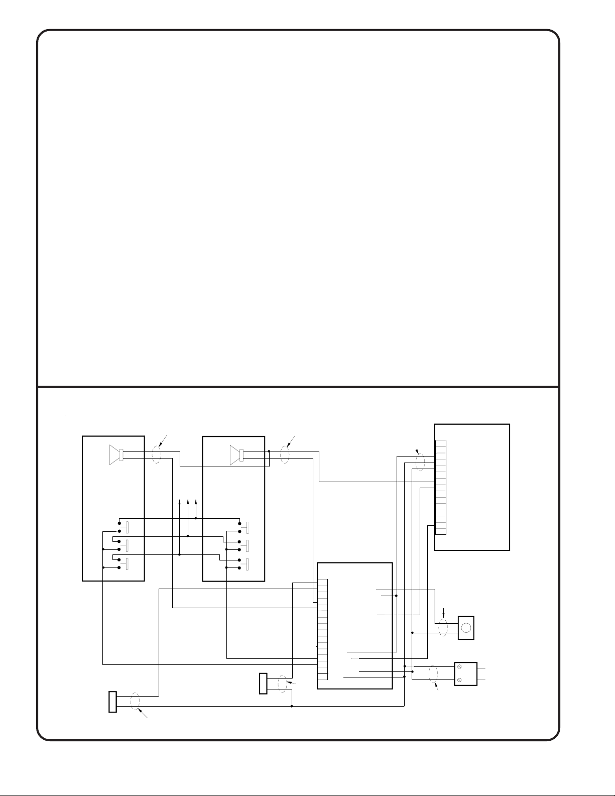
Figure 4—PK502B Wiring Diagram
for 2 Entrances Connected
to the PK205 Amplifier
PK205
AMPLIFIER
A
COM.
B
WIRES
C
D
M
MIC.
G
ZTBUZZ
SPKR.
P.O.SE
16 VAC.
L
D.R.
K
COM.
PK502B
#18
P.O. LOCK
ADAPTER
#18
16 VOLT
TRANSFORMER
CONNECT TO
117 VAC
Figure 5—PK502B Wiring Diagram for 3 to 8 Entrances Connected to the PK205 Amplifier
#22 TWISTED PAIR SHIELDED CABLE
CONNECT SHIELD TO TERM. G
(K)
(S2)
(M2)
+
(G)
AT THE AMPLIFIER.
ENTRANCE PANEL
SPEAKER SPEAKER SPEAKER
PUSH BUTTON
(Z2)
(D2)
DOOR
RELEASE
(K)
#18
NOTES:
1. USE #22 WIRE UNLESS SHOWN OTHERWISE.
2. USE SHIELDED WIRE FOR MICROPHONES AS SHOWN.
3. CONNECT SPEAKER COMMONS DIRECTLY TO THE AMPLIFIER.
4. CONNECT REMOTE STATION COMMON WIRING AS REQUIRED FOR SINGLE ENTRANCE.
#22 TWISTED PAIR SHIELDED CABLE
CONNECT SHIELD TO TERM. G
ENTRANCE PANEL ENTRANCE PANEL
AT THE AMPLIFIER.
(K)
(S1)
(M1)
+
(G)
TO REMOTE STATION
X TERMINALS
PUSH BUTTON
(Z1)
DOOR
RELEASE
(D1)
(K)
#18
PK502B
TRANSFER RELAY
BLUE/WHITE
D1
GREEN WHITE
D2
D0
YELLOW/WHITE
ORANGE/WHITE
S1
RED/WHITE
S2
BROWN/WHITE
S0
WHITE
M1
BLACK
M2
M0
GREY
Y1
BROWN
Y2
VIOLET
R
BLUE
Z1
GREEN
Z2
YELLOW
C
ORANGE
K
RED
REPEAT THIS SECTION TO ADD MORE ENTRANCES (SEE INSTRUCTIONS).
(K)
(S2)
(M2)
+
PUSH BUTTON
(Z2)
(D2)
DOOR
RELEASE
(K)
#22 TWISTED PAIR SHIELDED CABLE
CONNECT SHIELD TO TERM. G
AT THE AMPLIFIER.
(G)
PK502B
TRANSFER RELAY
BLUE/WHITE
D1
GREEN WHITE
D2
D0
YELLOW/WHITE
ORANGE/WHITE
S1
RED/WHITE
S2
BROWN/WHITE
S0
WHITE
M1
BLACK
M2
M0
GREY
Y1
BROWN
Y2
VIOLET
R
BLUE
Z1
GREEN
Z2
YELLOW
C
ORANGE
K
RED
#18 #18
IL499 PK502B PK205 THREE ENTRANCE REV1 060204 1
AMPLIFIER
#18
P.O. LOCK
ADAPTER
#18
16 VOLT
TRANSFORMER
PK205
A
COM.
B
WIRES
C
D
M
MIC.
G
ZTBUZZ
SPKR.
P.O.SE
16 VAC.
D.R.
L
COM.
K
CONNECT TO
Connect to D1 or D2
Terminal that connects
to front door strike.
117 VAC
Page 4 • IL499 PK502B Installation Instructions
Copyright © TekTone Sound & Signal Mfg., Inc. All Rights Reserved.
 Loading...