

Page 1
TECHNOLOGY
USER MANUAL
Jazz (RF-SERIES)
GB2 Video Door
Entry System Kit
2-wire installation
Includes Proximity Reader
and Fish-Eye Camera
http://alphacommunications.com
AWD262
Rev 1 - 01/2018
Page 2

JAZZ GB2 VIDEO DOOR ENTRY SYSTEM KIT - HOUSE
INTRODUCTION
First of all, we thank and congratulate you for purchasing this product.
Our commitment to achieving the satisfaction of customers like you is manifested through our ISO-9001 certification
and the manufacture of products like the one you have just purchased.
Its advanced technology and strict quality control will ensure that customers and users enjoy the numerous features
that this device offers. To get the most out of them and ensure proper operation from day one, we recommend that you
read this instruction manual.
CONTENTS
Introduction....................................................................................................................................................................2
Contents.......................................................................................................................................................... .............2. .
Set-up warnings............................................................................................................... .................2.............................
Safety precautions.................................................................................................................... ........................3............. .
Characteristics and functioning of the system.................................................................................................... .........3....
Description of JAZZ surface panel (with proximity reader)............................................................................ ........ 4.......... .
Exploded view of the parts of the panel.................................................................................................................... ....5... .
Description of the TK3401/GB2 proximityaccess key kit........................................................................... ......... 5............ .
Door panel............................................................................................................................................................ ............
Location of the door panel
Installing the power supply unit (FA-GB2/A)and lock release
Wiring diagrams with the PENTHAmonitor............................................................................................ ....... 15-20.......... .
Connection diagrams for up to 4 access panels.................................................................................... ................... 21.....
Connection diagrams withAC lock release, 2nd AC lock release or automatic gate.................. ............22.........................
N ...........................................................................................................................................................................23
otes
................................................................................................................................ ..........5.. .
................................................................................................................................. ........6....Removing the metal front
................................................................................................................................ ......... 6.. .Positioning the door panel
......................................................................................................................................... ........6..Wiring the door panel
.............................................................. ..........................7......................Codes assigned to the door panel call buttons
................................................................................................ ........ 7...............................Description of the DIP switch
................................................................................................... .................8....Description of the configuration jumper
................................................................... .........8................ .Descriptionof the illumination LEDs (low light conditions)
.................................................................................................. ...8...Description of the visual signals on the door panel
.............................................................................................. .............8..Setting the door panel communication volume
.................................................................................... .................9.............................Setting ringtone operating mode
........................................................................................... . 9... .Setting door panel mode with or without shield installed
................................ ............... 9........... .Setting contact mode for CV-/CV+ (lock release)and C1/NA1 (auxiliary device)
.................................... ..... 10........ .Setting the activation time for CV-/CV+(lock release) and C1/NA1 (auxiliary device)
...................................................................... ..............10....................Setting card reader illumination operating mode
.......................................................................... ...10.....................Setting door panel illumination LED operating mode
........................................................................................................................ .........11..Setting the door panel address
........................................................................................................................... .... 11..Positioning the nameplate label
.................................................................................... .........11.....................Positioning the button identification labels
........................................................................................... ......... 12........ .Managing the accesskeys (proximity reader)
..................................................................................................................................... .......13... .Closing the doorpanel
......................................................................... .............14..
2
SET-UP WARNINGS
- Do not overtighten the screws on the power supply connector.
- Always disconnect the power supply before installing or making modifications to the devices.
- The fitting and handling of these devices must be carried out by .authorised personnel
- The wiring must run at least .40cm away from any other wiring
- Before connecting the device to the mains, check the connections between the door panel, power supply unit,
distributors, camera interface, GSM interface and monitors.
- Use the Golmar cable (2x1mm ).RAP-2150
- Always follow the instructions contained in this manual.
2
Page 3
JAZZ GB2 VIDEO DOOR ENTRY SYSTEM KIT - HOUSE
SAFETY PRECAUTIONS
- Always disconnect the power supply before installing or making modifications to the devices.
- The fitting and handling of these devices must be carried out by .authorised personnel
- The wiring must run at least 40 cm away from any other wiring.
- On the power supply unit:
wDo not overtighten the screws on the connector.
wInstall the power supply unit in a dry protected location free from the risk of dripping or splashing water.
wAvoid locations thatare humid, dusty or near heat sources.
wEnsure that the air vents are free from obstruction so that air can circulate freely.
wTo avoid damage, the power supply unit must be firmly secured in place.
wTo prevent electric shock, do not remove the cover or handle the wires connected to the terminals.
CHARACTERISTICS
- Video door entrysystem with simplified wiring (non-polarised 2-wire bus).
- Up to 4 access panels (DP-GB2Adistributor required for more than one access panel) per installation.
- Up to 2 apartments per installation (JAZZ/2RF 2-button surface panel required).
- Maximum 4 Pentha monitors per installation.
- In installations with 1 apartment, maximum 4 Pentha monitors.
- In installations with 2 apartments, maximum 4 Pentha monitors.
- Combinations:
w1 monitor in one apartment and 3 monitors in the other apartment.
w2 monitors in each apartment.
-Visual signals on the door panel for people with impaired hearing (indicating call process, communication, door open
and channel busy).
- Proximity key reader for door opening (output 'CV-'and 'CV+' on the door panel).
- Door opening and auxiliary device activated for 5 seconds (configurable).
- DC lock release.
- Potential-free contact for activation of auxiliary devices (2nd AC lock release, gate, etc.); do not exceed values of
12Vdc/1Abetween terminals 'C1' and 'NA1' on the door panel.
- Input for exterior door opening button (output 'CV-'and 'CV+' of the door panel).
- Confirmation tone when the call button is pressed.
- DIP switches to configure door panel address, call mode, door
release and auxiliary device output, card reader illumination mode, LED function mode (low light conditions) and create
new proximity cards with 'MasterAdd'and 'Master Delete'.
- Maximum distance between the power supply and the furthest door panel: 65m with a cross-section of 1mm .
- Maximum distance between the power supply and the last distributor: 60m with a cross-section of 1mm .
- Maximum distance between distributor and monitor: 30m with a cross-section of 1mm .
panel with/without shield, type of contact/time for lock
2
2
2
3
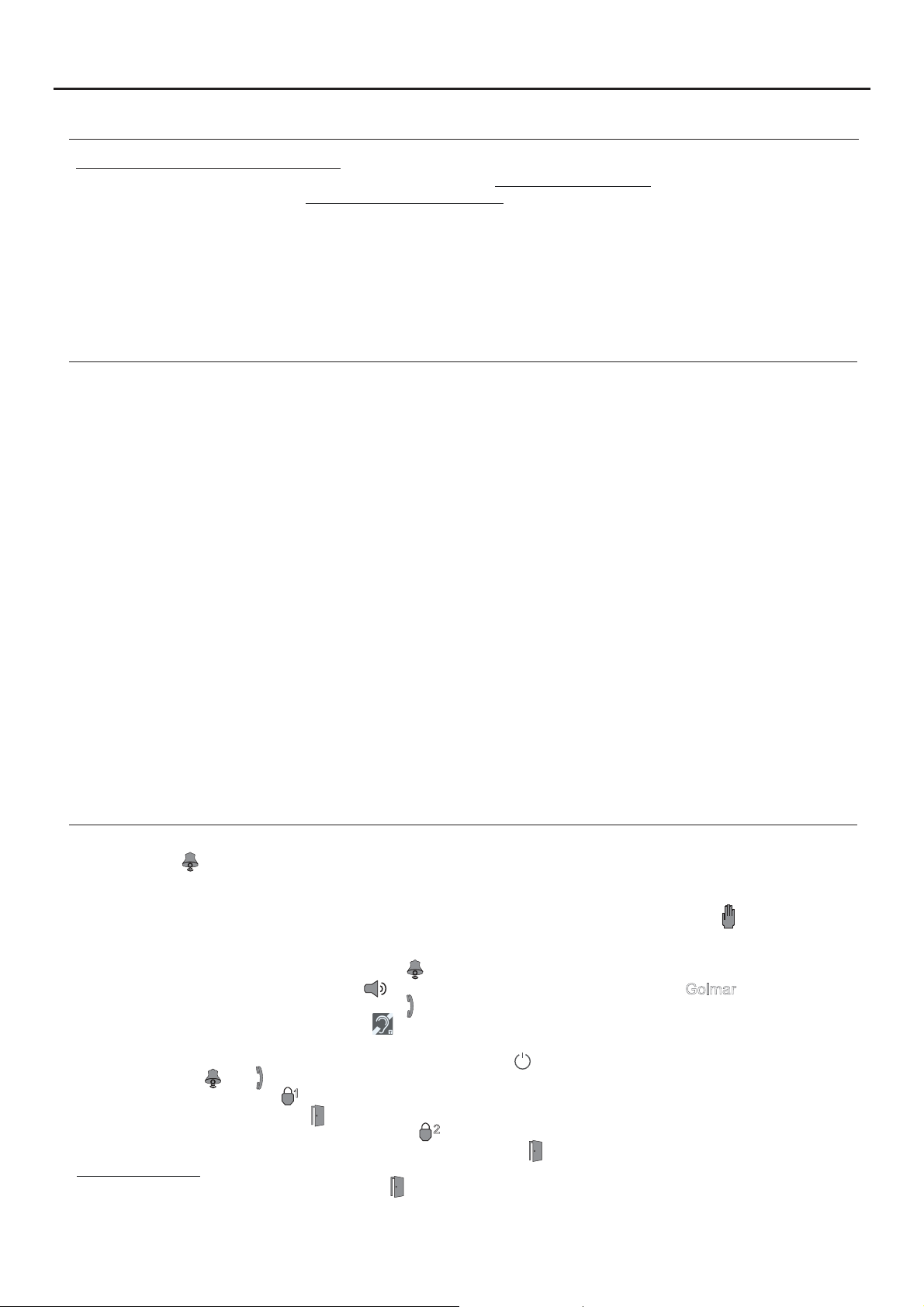
SYSTEM OPERATION
- To make a call, the visitor must press the button of the apartment; an audible sound indicates that the call is being
made and LED will turn on. At this moment,the apartment's monitors receive the call.If another apartment is called
by mistake, press the button for the correct apartment and the first call will be cancelled.
- In systems with several access doors, the other door panel(s) will be automatically disconnected. If another visitor
tries to call, a number of telephone tones will be heard to indicate that the system is busy and LED will illuminate.
- The call lasts for 40 seconds. The image appears on the monitor (with code 0 'apartment 1' or code 16 if the call is in
'apartment 2') when receiving the call without the visitor knowing.
If the call is not answered within 40 seconds, LED will turn off and the channel will be freed.
- To establish communication, press option on the screen of the master monitor or the logo on the frontGolmar
of any slave monitor in the apartment, and LED on the door panel will illuminate.
If the monitor is a PENTHA GB2/H with icon on the front, make sure that the hearing aid is between 15 and 25 cm
from the monitor to ensure maximum audio quality during communication with the door panel.
away
- Communication will last for one and a half minutes or until option on the screen is pressed. When communication
has finished, LEDs and will turn off and the channel will be freed.
- To open the door, press option on the screen during the call or communication processes: one press will activate the
lock releasefor 5 secondsand LED will also illuminate for 5 seconds.
- To activate theauxiliary device output, pressoption on the screen during thecall or communication processes: one
press will activate the auxiliary device output for 5 seconds and LED will also illuminate for 5 seconds.
- Proximity reader: To open the door without making a call, hold the access key to the proximity reader of the door panel,
the door will be activatedfor 5 seconds and LED will also illuminate for 5 seconds.
1
2
Page 4
JAZZ GB2 VIDEO DOOR ENTRY SYSTEM KIT - HOUSE
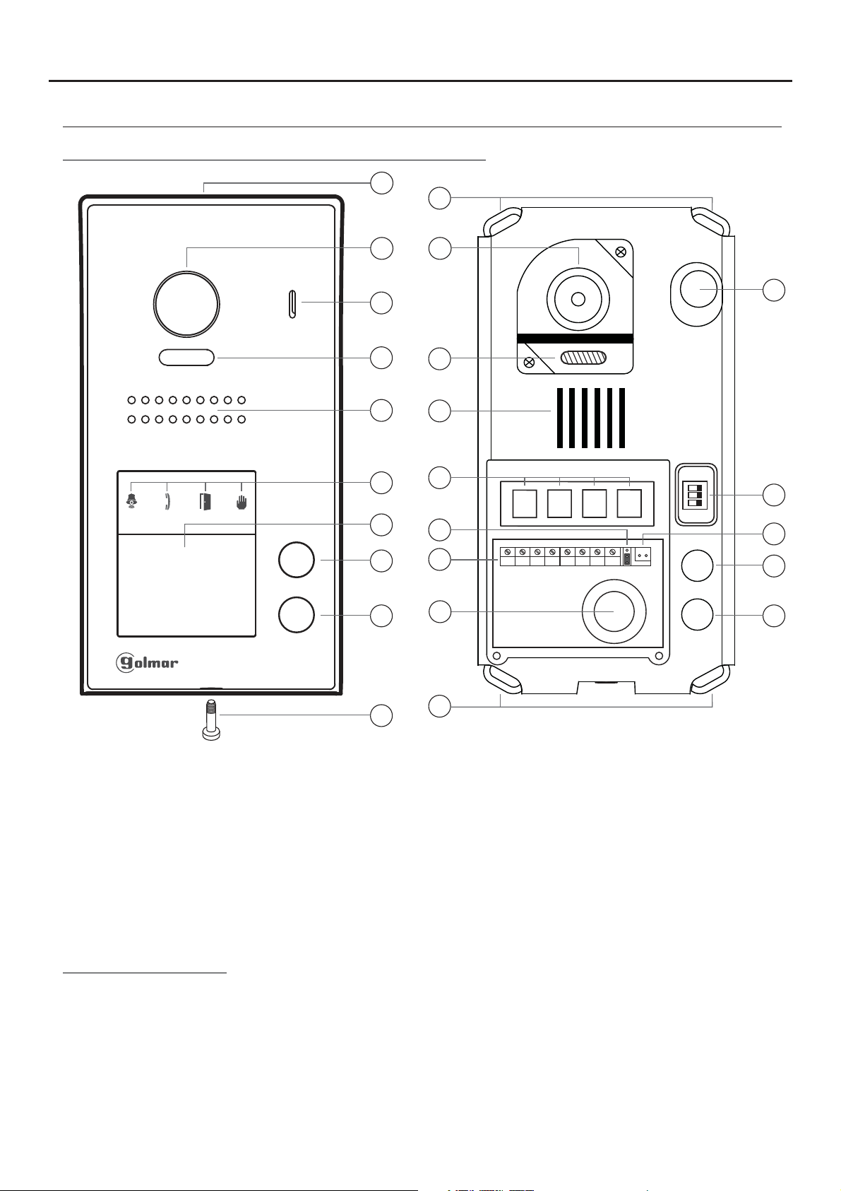
DESCRIPTION OF THE JAZZ SURFACE PANEL
Description of Jazz surface panel (with proximity reader):
a
k
4
b
c
d
e
g
h
b
c
d
e
f
i
f
m
n
1 2 3
ON
l
AP-
AP+
NA1
C1
CV+
CV- BUSBUS
o
p
h
i
a.
Shield.
b. Colour television camera.
c. Microphone.
d. LEDs (activation with ambient light).
e. Speaker.
f. LEDs (visual signals for people with
impaired hearing).
g. Nameplate label with proximity card reader.
h. Call button apartment 2.
(2-button door panel model only).
Connection terminals:
_
AP +,AP :
C1
NA1
_
CV ,CV+
BUS
BUS
Input for exterior door opening button (CV-, CV+).
: Contact 'C' for auxiliary device (2nd AC lock release, gate, etc.).
: Contact 'N.O.' for auxiliary device (2nd AC lock release, gate, etc.).
: S12Vdc output for Golmar DC electric lock.
: Communication BUS (non-polarised).
: Communication BUS (non-polarised).
j
k
i. Call button apartment 1.
j. Metal front fixing screw (x1).
k. Holes for fixing to wall (x4).
l. Do not use (internal use).
m.Connection terminals.
n. Wiring entry.
o. DIP switch.
p. Proximity reader connection contacts.
Note: See wiring diagrams for connections (pp. 15-22).
Page 5
JAZZ GB2 VIDEO DOOR ENTRY SYSTEM KIT - HOUSE
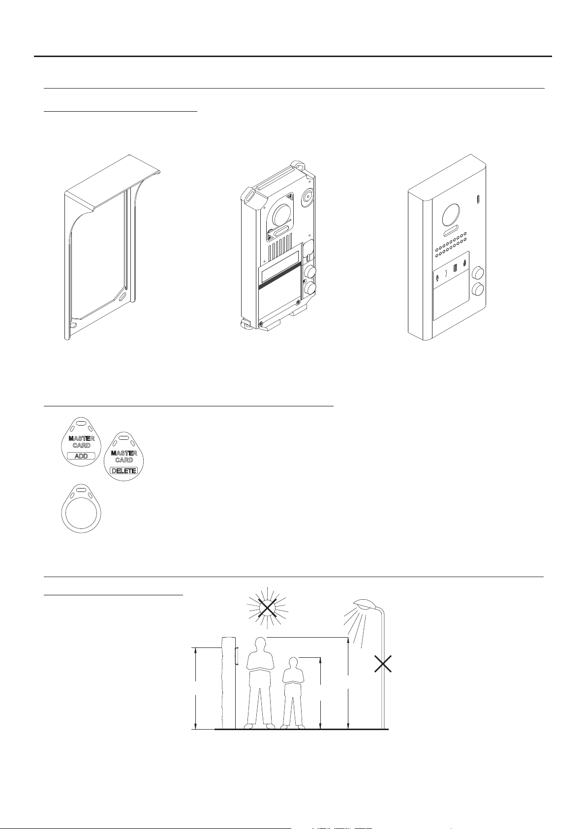
DESCRIPTION OF THE JAZZ SURFACE PANEL
Description of the door panel:
Exploded view of the parts of the panel.
5
Aluminium frontElectronic moduleShield
- JAZZ J5110/PENTHA 1P KIT (Code 11500243).
- JAZZ/1RF SURFACE PANEL (Code 11525551).
- JAZZ/2RF SURFACE PANEL (Code 11525552).
Description of the TK3401/GB2 proximity access key kit:
Management keys for adding/deleting residents' keys using the proximity reader. Supplied
MASTER
CARD
ADD
MASTER
CARD
DELETE
with the video door entry kit.
MASTER CARD ADD: Key for adding residents' proximity keys.
MASTER CARD DELETE: Key for deleting residents' proximity keys.
TAGKEY residents' access keys (Code 20740427).
X5
Note: Access keys configured from factory.
Note: To add/delete proximity keys, follow the instructions on pp. 12.
INSTALLATION OF THE DOOR PANEL
Location of the door panel:
1650
1850
1450
Locate the top of the door panel at a height of 1.65m.
The door panel has been designed to withstand diverse environmental conditions. It is however advisable to take
extra precautions to prolong its service life, such as using the shield supplied or locating it in a covered area.
For optimum image quality, avoid direct contact from light sources (sunshine, street lights, etc.)
.
Page 6
AP-
C1
NA1
AP+
CV- BUSBUS
CV+
JAZZ GB2 VIDEO DOOR ENTRY SYSTEM KIT - HOUSE
INSTALLATION OF THE DOOR PANEL
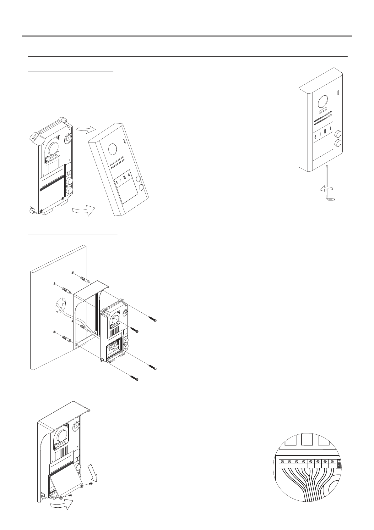
Removing the metal front:
Remove the screw at the bottom of the door panel
using the Allen key supplied with the product.
Remove the metal front as shown in the drawing.
6
Positioning the door panel:
Wiring the door panel:
Present the shield and the electronic module to the wall, placing
the top of the module at a height of 1.65m from the ground, and
pass the wiring through the cable entry.
Make 4 x 6mm diameter holes, two located at the top of the
module and the other two at the bottom, and fix the shield and
electronic module to the wall using the plugs and screws supplied.
Important: The distance between the top of theelectronic module
and the shield should be 7mm, so that the metal front can be
correctly positioned when closing the door panel.
To access the connection
terminals, remove the card
reader.
Then connect the wiring to the
connector strip of the electronic
module, following the instructions
in the wiring diagrams.
Page 7
ON
1 2 3
JAZZ GB2 VIDEO DOOR ENTRY SYSTEM KIT - HOUSE
INSTALLATION OF THE DOOR PANEL
Codes assigned to the door panel call buttons:
1 2 3
ON
AP-
AP+
The sound module's P1 and P2 buttons are assigned with factory codes.
NA1
C1
CV+
CV- BUSBUS
Button 'P2': Codes 16-21..
(Apartment 2) 2-button door panels only.
Button 'P1': Codes 0-5.
(Apartment 1).
7
- Apartment 1, button 'P1': Enables codes 0-5 to be assigned to the monitor.
Monitors in this apartment must be set with codes in order of allocation from 0 to 5.
When button 'P1' on the door panel is pressed, all of the monitors in apartment 1 will receive the call and only
the monitor assigned with code 0 will show the door panel image. If the call is answered from any other
monitor in the apartment, the image on the monitor assigned with code 0 will disappear and audio and video
communication will be established with the door panel.
- Apartment 2, button 'P2': Enables codes 16-21 to be assigned (2-button door panel only).
Monitorsin this apartment must be set with codes in order of allocationfrom 16 to 21.
When button 'P2' on the door panel is pressed, all of the monitors in apartment 2 will receive the call and only
the monitor assigned with code 16 will show the door panel image. If the call is answered from any other
monitor in the apartment, the image on the monitor assigned with code 0 will disappear and audio and video
communication will be established with the door panel.
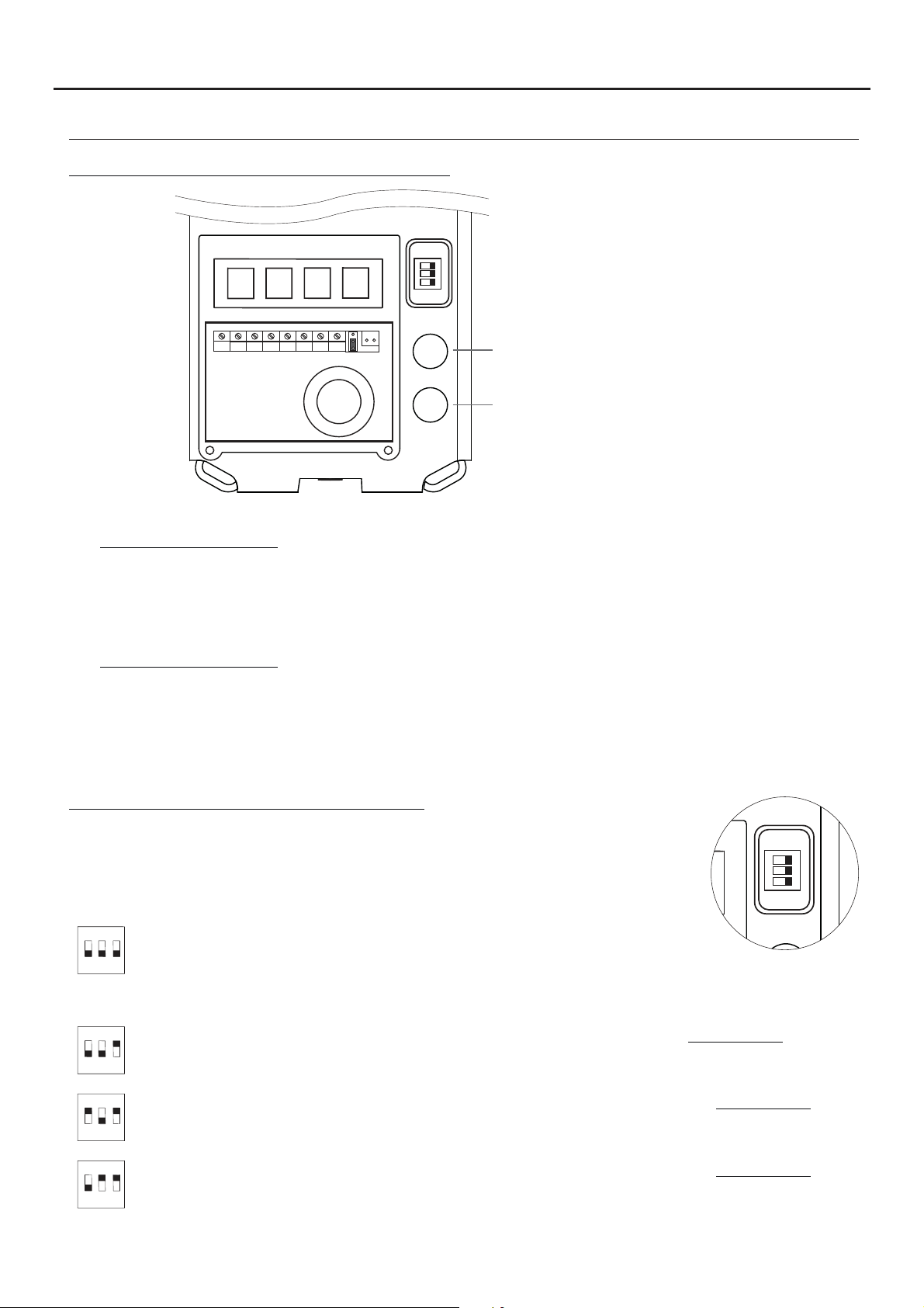
Description of the configuration DIP switch:
The configuration DIP switch is located on the right side of the electronic module,
accessible by opening the door panel (remove the protective silicone cover).
1. To select the address of the door panel (DIP 3 must always be OFF):
( )
*
ON
1 2
Door panel address: (DIP 3 always OFF).
DIP switches: 1 and 2 OFF (address 1), 1 ON and 2 OFF (address 2), 1 OFF and 2
3
ON (address 3), 1 and 2 ON (address 4).
( )
*
2. To configure the door panel (DIP 3 must always be ON):
ON
1 2
ON
1 2
ON
1 2
( )
Factory setting.
*
With DIP 1 and DIP 2 OFF (DIP 3 always ON), the following can be configured: See pp. 9-10.
-With button 'P1', ringtone operating mode during a call process.
3
-With button 'P2', whether the door panel is installed with or without shield.
With DIP 1 ON and DIP 2 OFF (DIP 3 always ON), the following can be configured: See pp. 9-10.
-With button 'P1', lock release output 'CV-' and 'CV+', whether N.O. (factory setting) or N.C.
3
-With button 'P2', activation time of lock release and auxiliary device outputs.
With DIP 1 OFF and DIP 2 ON (DIP 3 always ON), the following can be configured: See pp. 9-10.
-With button 'P1', operating mode of card reader illumination.
3
-With button 'P2', operating mode of door panel illumination LEDs with low light.
Page 8
JAZZ GB2 VIDEO DOOR ENTRY SYSTEM KIT - HOUSE
INSTALLATION OF THE DOOR PANEL
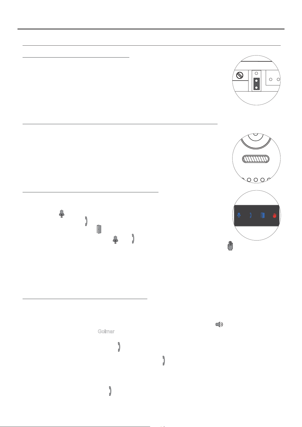
Description of the configuration jumper:
Important: Do not change the configuration jumper's factory position.
( )
Factory setting.
*
Description of the door panel illumination LEDs (for low light conditions):
The door panel lighting LEDs will turn on during a call if the door panel lighting at
that moment is low. This enables the user to view the person who has called
from the apartment monitor.
( )
*
8
Description of the visual signals on the door panel:
Visual signals on the door panel for people with impaired hearing, indicating:
- In call: LED ' ' will illuminate during in call and in communication times.
- In communication: LED ' ' will illuminate during the communication process.
*
- When the door is open: LED ' ' will illuminate when the door is open.
- When ending communication: LEDs ' ' and ' ' will turn off.
- With more than one door panel, when calling and one is already in communication: LED ' ' will illuminate for
10 seconds.
- In call and the monitor is in 'Do not disturb' mode: No LED will illuminate, the door panel will emit a quick tone.
- In call (apartment without monitor or telephone): No LED will illuminate, the door panel will emit 3 quick tones.
Note: Communication in auto switch-on mode does not occupy the channel and the door panel communication LED
*
does not illuminate.
Setting the door panel communication volume:
If the audio volume of the door panel is too low after turning it on, follow these steps:
- Call the apartment.
- The call is received in the apartment. Establish communication by pressing option on the screen of the
master monitor or the logo on the front of any slave monitor in the apartment.
- Then press the button used to call the apartment for 3 seconds until a number of confirmation tones are heard
and door panel communication LED starts to blink.
- Each press on the call button will increase the door panel volume and blink speed of the LED.
.
There are 5 volume settings and the blink speed of LED will increase for each. Slow to fast blink - low to
high volume. After reaching setting 5,maximum blink speed and volume, thenext setting is 1, minimum blink
speed and volume (carousel mode).
- To save the volume setting, keep the button pressed until a number of confirmation tones are heard and the
door panel communication LED turns on.
Golmar
Page 9

P1
P2
P1
JAZZ GB2 VIDEO DOOR ENTRY SYSTEM KIT - HOUSE
INSTALLATION OF THE DOOR PANEL
Setting ringtone operating mode:
To configure the door panel ringtone when making a call, follow these steps: See p. 7.
- In the configuration DIP switch, set DIP 1 and DIP 2 to OFF and DIP 3 to ON.
- The card reader illumination will blink slowly.
- Then with the P1 call button, each press selects a different option and in carousel mode:
If pressed once: Configure the door panel with one ringtone.
LED illuminates and the door panel emits a long tone.
If pressed : Configure the door panel to hear tones during the call process.a 2nd time
LED illuminates and the door panel emits two tones.short
If pressed : Configure the door panel without a ringtone (factory setting).a 3rd time
LEDs and illuminate and the door panel emits three tones.short
- Once the required option is selected, stop pressing P1. Then set DIP 3 to OFF and the door panel will exit
configuration, saving the selected option. Remember to configure the address of the door panel.Note:
9
Setting door panel mode with or without shield installed:
To configure the door panel with or without shield installed, follow these steps: See p. 7.
- In the configuration DIP switch, set DIP 1 and DIP 2 to OFF and DIP 3 to ON.
- The card reader illumination will blink slowly.
- Then with the P2 call button, each press selects a different option and in carousel mode:
If pressed once: Configure the door panel with shield installed (factory setting).
LED illuminates and the door panel emits a long tone.
If pressed : Configure the door panel without shield installed.a 2nd time
LED illuminates and the door panel emits two tones.short
- Once the required option is selected, stop pressing P2. Then set DIP 3 to OFF and the
door panel will exit configuration, saving the selected option.
Note: Remember to configure the address of the door panel.
Setting contact mode for CV- and CV+ (lock release) and C1 and NA1 (auxiliary device):
To change the contact mode for lock release and auxiliary device activation, follow these steps: See p. 7.
- In the configuration DIP switch, set DIP 1 to ON, DIP 2 to OFF and DIP 3 to ON.
- The card reader illumination will blink slowly.
- Then with the P1 call button, each press selects a different option and in carousel mode:
If pressed once: Configure the door panel with contact mode N.A. (factory setting).
LED illuminates and the door panel emits a long tone.
If pressed : Configure the door panel with contact mode N.C.a 2nd time
LED illuminates and the door panel emits two tones.short
- Once the desired option is selected, set DIP 3 to OFF and the door panel will exit
configuration, saving the selected option.
Note: Remember to configure the address of the door panel.
Important: The type of contact selected will be for both the lock release and the auxiliary device.
Page 10

P2
P1
P2
JAZZ GB2 VIDEO DOOR ENTRY SYSTEM KIT - HOUSE
INSTALLATION OF THE DOOR PANEL
Setting the activation time for CV- and CV+ (lock release) and C1 and NA1 (auxiliary device):
To change the activation time for the lock release and auxiliary device, follow these steps: See p. 7.
- In the configuration DIP switch, set DIP 1 to ON, DIP 2 to OFF and DIP 3 to ON.
- The card reader illumination will blink slowly.
- Then press and hold down call button P2; LED will blink indicating with each blink 1 second and also a tone
will indicate every time it is heard 1 second for the activation time.
Once the desired activation time is configured, set DIP 3 to OFF and the door panel will exit
-
configuration, saving the setting.
Note: Remember to configure the address of the door panel.
Important: The time configured will be for both the lock release and the auxiliary device.
Setting card reader illumination operating mode:
Note: (From 1 to 99 seconds).
10
To configure the card reader illumination operating mode, follow these steps: See p. 7.
- In the configuration DIP switch, set DIP 1 to OFF, DIP 2 to ON and DIP 3 to ON.
- The card reader illumination will blink slowly.
- Then with the P1 call button, each press selects a different option and in carousel mode:
If pressed once: Card reader always illuminated (factory setting).
LED illuminates and the door panel emits a long tone.
If pressed : Card reader always off.a 2nd time
LED illuminates and the door panel emits two tones.short
If pressed time: The card reader automatically turns on or off dependinga 3rd
on the ambient light (day/night mode).
LEDs and illuminate and the door panel emits three tones.short
- Once the required option is selected, stop pressing P1. Then set DIP 3 to OFF and the door panel will exit
configuration, saving the selected option. Remember to configure the address of the door panel.Note:
Setting door panel illumination LED operating mode:
To configure the door panel illumination LED operating mode, follow these steps: See p. 7.
- In the configuration DIP switch, set DIP 1 to OFF, DIP 2 to ON and DIP 3 to ON.
- The card reader illumination will blink slowly.
- Then with the P2 call button, each press selects a different option and in carousel mode:
If pressed once: Illumination LEDs always activate when a call is made from the door panel.
LED illuminates and the door panel emits a long tone.
If pressed : Illumination LEDs always off.a 2nd time
LED illuminates and the door panel emits two tones.short
If pressed : Illumination LEDs activate when a call is made and door panela 3rd time
illumination at that moment is low (factory setting).
LEDs and illuminate and the door panel emits three tones.short
- Once the required option is selected, stop pressing P2. Then set DIP 3 to OFF and the door panel will exit
configuration, saving the selected option. Remember to configure the address of the door panel.Note:
Page 11

ON
1 2 3
JAZZ GB2 VIDEO DOOR ENTRY SYSTEM KIT - HOUSE
INSTALLATION OF THE DOOR PANEL
Setting the door panel address:
11
Configure door panel addresses as described below:
The DIP switch is located on the right side of the circuit, accessible by opening the
door panel.
ON
( )
*
1 2 3
Important: To select the address of the door panel (DIP 3 must always be OFF):
Door panel address: (DIP 3 always OFF).
DIP switches: 1 and 2 OFF (address 1), 1 ON and 2 OFF (address 2), 1 OFF and 2
ON (address 3), 1 and 2 ON (address 4).
Positioning the :nameplate label
After completing the wiring and configuration work, position the
nameplate label in the electronic module. Fix using the screws
supplied.
Important: Before closing the , make a test callnameplate label
to the apartment(s) to ensure that it works correctly.
( )
*
Important: Position the at the top with the black band visible.nameplate label
Positioning the button identification labels:
Open the label cover (figure A ), insertthe label (figure B ) and close(figure C ).
A B C
Open the label cover
( )
*
( )
*
Page 12

JAZZ GB2 VIDEO DOOR ENTRY SYSTEM KIT - HOUSE
P1
INSTALLATION OF THE DOOR PANEL
Managing the access keys:
The kit enables activation of the video door entry system's lock release with proximity access keys (without placing a
call). Supplied with the product are 1 Master CardADD key, 1 Master Card DELETE key and 5 residents access keys
(factory assigned to the door panel) ee 'Description of the proximity access key kit' on p. 5)., s
Adding access keys:
To add residents' access keys for activation of the lock release connected to terminals 'CV-' and 'CV+' of the door
panel, follow these steps:
- Hold the Master Card ADD key to the proximity reader, it will emit a long and short confirmation tone and LED
on the door panel will turn on.
- One by one, hold all ofthe keys to be addedto the door panel tothe proximity reader. The doorpanel will emit a long
tone each time it stores an access key or two short tones if the key has already been stored.
- Once all of the access keys are added, complete the process by holding the Master Card ADD key to the proximity
reader.It will emit a short and long confirmation tone and LED will turn off.
Deleting access keys:
To delete residents' access keys, follow these steps:
- Hold the Master Card DELETE key to the proximity reader, it will emit a long and short confirmation tone and
LED on the door panel will turn on.
- One by one, hold all of the keys to be deleted from the door panel to the proximity reader. The door panel will emit a
long tone each time it deletes an access key or two short tones if the key does not exist on the door panel.
- Once all of the access keys are deleted, complete the process by holding the Master Card DELETE key to the
proximity reader.It will emit a short and long confirmation tone and LED will turn off.
12
Deleting all access keys:
To delete all residents' access keys, follow these steps:
- Hold the Master Card DELETE key to the proximity reader, it will emit a long and short confirmation tone and LED
on the door panel will turn on.
- Then hold the Master Card ADD key to the proximity reader, it will emit a long and short confirmation tone and
LED on the door panel will illuminate indicating that it is in mode.'Delete All Keys'
- Finally, hold the Master Card ADD key again to the proximity reader to confirm deletion of all of the residents' keys
from the door panel. During the deletion process, LEDs and will blink. Once the deletion process is complete,
they will turn off.
Activating new MASTER CARD keys on the door panel:
To activate new Master Card ADD andDELETE keys on the door panel, follow these steps:
- Disconnect the door panel's power supply.
- In the configuration DIP switch (seep. 7), set DIP 1, DIP 2 andDIP 3 to ON.
- Press call button P1.
- Keep call button P1 pressed and, without releasing it, turn on the power.
- The card reader illumination will blink slowly.
- In the configuration DIP switch (seep. 7), set DIP 1 and DIP 2 toOFF.
- Then press call button P1, a confirmation tone will be emitted and LED will blink once. You then have 10
seconds to perform the following step.
- Hold the Master Card ADD key to the proximity reader. Once stored, two confirmation tones will be emitted and
LED on the door panel will blink twice.
Then hold the Master Card DELETE key to the proximity reader. Once stored, three confirmation tones will be
emitted and LED on the door panel will blink three times.
- Once the new Master Card ADD and DELETE keys have been activated, set DIP 3 to OFF and the door panel will
exit configuration, saving the setting.
Note: A door panel can only have one Master Card ADD and one Master Card DELETE key. If new Master Card keys
are activated on the door panel (for example, due toloss), the previous Master Card keys will be deleted.
The same Master Card keys can be activated on other access panels installed.
Page 13

JAZZ GB2 VIDEO DOOR ENTRY SYSTEM KIT - HOUSE
INSTALLATION OF THE DOOR PANEL
Closing the door panel:
To finish the mounting of the door panel, replace
the metal front.
Note: Replace the DIP switch's protective
Protective cover
*
*
silicone cover.
13
Fix the metal front with the screw using the Allen key
supplied with the product, as shown in the drawing.
Once work is complete:
- Make a test call to the house(s) to check it works correctly.
-Hold anaccess key to the proximityreader to check it works
correctly.
Page 14

JAZZ GB2 VIDEO DOOR ENTRY SYSTEM KIT - HOUSE
INSTALLATION OF THE POWER SUPPLY UNIT
Installing the FA-GB2/A power supply unit:
Install the power supply unit in a dry protected location free from the risk of dripping or splashing water.
To prevent electric shock, do not remove the protective cover of the primary or handle the wiring.
The fitting and handling of this device must be carried out by in the absence ofauthorised personnel
electrical current.
To avoid damage, the power supply unit must be firmly secured in place.
Please note that current regulations stipulate that the
DIN rail.
power supply must be protected by a circuit breaker.
Connect the FA-GB2/A power supply unit to the earth
connection.
Mount the DIN rail to the wall with the plugs and screws
supplied.
Then attach the power supply by applying slight
pressure.
14
DIN rail.
DIN rail.
The power supply can be installed on a DIN 46277 rail.
.
To remove the power supply unit from the DIN rail, use a flat
screwdriverto lever it off, as shown in the drawing.
The FA-GB2/Amodel requires 8 elements on the rail.
DIN rail latch release.
DIN 46277
IMPORTANT: the maximum number of units that can be connected to an FA-GB2/A power supply is 4
PENTHAGB2 monitors.
Replace the protective cover once the input terminals have been wired.
INSTALLATION OF THE LOCK RELEASE
Installing the lock release:
3,5 x 25
DIN-7972
If the lock release is to be fitted to a metal door, use a Ø3.5mm drill bit and
thread the hole made. For wooden doors, use a Ø3mm drill bit.
M 4 x 8
DIN-963
IMPORTANT:
- The lock release must be 12V DC orAC (Golmar).
(See p. 22 forAC lock release and pp. 15-22 for DC lock release).
- The kit is supplied with two varistors. If connecting an AC lock release to one of the outputs, fit the varistor
supplied directly to the lock release terminals to ensure the device functions correctly.
Page 15
JAZZ GB2 VIDEO DOOR ENTRY SYSTEM KIT - HOUSE
WIRING DIAGRAMS:
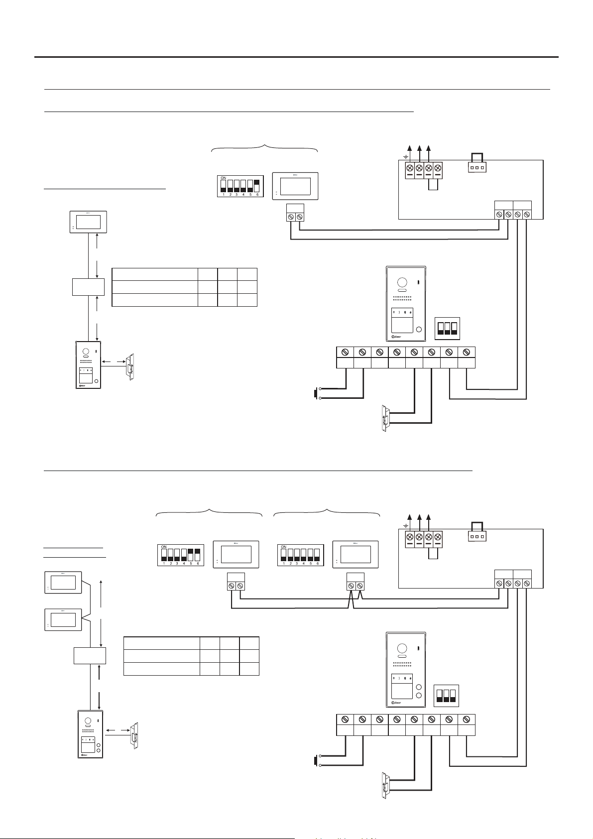
One-apartment installation with PENTHA monitor and Golmar DC lock release.
15
Distances and cross-sections:
PENTHA
B
Cable
FA- 2GB /A
Twisted pair 2x0.75mm
Twisted pair 2x1mm
( )2
( )2
A
Distances with Golmar RAP-2150 cable
(twisted pair 2x1mm ).
C
Configure the end of line in
*
the last monitor.
DIP 6 to ON.
*
2
6 m0A50mB10m
2
65m 60m 15m
2
APARTMENT 1
CODE 0
C
PENTHA
BUS
AP+
AP
Lock release
max. 12 Vdc/270mA.
AP-
( )1
Mains
100~240Vac
Access panel
NA1
C1
CV- BUSBUS
( )1
N L
L
CV+
SW1
ON
1 2 3
CN
FA- 2GB /A
BUS (M) BUS(PL)
Two-apartment installation with 1 PENTHA monitor per house and Golmar DC lock release.
Mains
100~240Vac
N L
NA1
CV- BUSBUS
( )1
L
CV+
SW1
ON
1 2 3
FA- 2GB /A
Distances and
cross-sections:
PENTHA
PENTHA
B
FA- 2GB /A
A
CODE 16
*
Cable
Twisted pair 2x0.75mm
( )2
Twisted pair 2x1mm
( )2
Distances with Golmar RAP-2150 cable
(twisted pair 2x1mm ).
C
2
6 m0A50mB10m
2
65m 60m 15m
2
PENTHA
BUS
APARTMENT 1APARTMENT 2
CODE 0
PENTHA
BUS
Access panel
C
AP-
AP+
C1
CN
BUS (M) BUS(PL)
Configure the end of line in
AP
*
the last monitor.
DIP 6 to ON.
( )1
Important: For AC lock release, 2nd AC lock release or automatic gate, see wiring diagrams p. 22.
Lock release
max. 12 Vdc/270mA.
( )1
Page 16

JAZZ GB2 VIDEO DOOR ENTRY SYSTEM KIT - HOUSE
WIRING DIAGRAMS:
One-apartment installation with 4 PENTHA monitors in parallel (In-Out) and Golmar DC lock release.
NOTE: Up to 4 Pentha monitors per installation.
APARTMENT 1
CODE 3
CODE 2
*
BUS
Distances and cross-sections:
PENTHA
BUS
CODE 1
PENTHA PENTHAPENTHAPENTHA
CODE 0
BUS
BUS
Access panel
Mains
100~240Vac
N L
L
CN
FA- 2GB /A
16
BUS (M) BUS(PL)
B
FA- 2GB /A
A
Cable
Twisted pair 2x0.75mm
( )2
Twisted pair 2x1mm
( )2
Distances with Golmar RAP-2150 cable
(twisted pair 2x1mm ).
Configure the end of line in the last monitor.
*
DIP 6 to ON.
2
6 m0A50mB10m
2
65m 60m 15m
2
C
C
AP-
AP+
C1
NA1
CV- BUSBUS
CV+
SW1
ON
1 2 3
( )1
AP
Lock release
max. 12 Vdc/270mA.
( )1
Instalación de dos viviendas con 4 monitores PENTHA en paralelo (In-Out) y abrepuertas de continua Golmar.
NOTE: Up to 4 Pentha monitors per installation.
CODE 17
CODE 16
*
BUS
Distances and cross-sections:
PENTHA
BUS
CODE 1
APARTMENT 1APARTMENT 2
PENTHA PENTHAPENTHAPENTHA
CODE 0
BUS
BUS
Access panel
Mains
100~240Vac
N L
L
CN
FA- 2GB /A
BUS (M) BUS(PL)
PENTHA
B
C
AP-
AP+
AP
Lock release
max. 12 Vdc/270mA.
FA- 2GB /A
A
Cable
Twisted pair 2x0.75mm
( )2
Twisted pair 2x1mm
( )2
Distances with Golmar RAP-2150 cable
(twisted pair 2x1mm ).
Configure the end of line in the last monitor.
*
DIP 6 to ON.
2
6 m0A50mB10m
2
65m 60m 15m
2
C
( )1
Important: For AC lock release, 2nd AC lock release or automatic gate, see wiring diagrams p. 22.
SW1
ON
1 2 3
C1
NA1
CV+
CV- BUSBUS
( )1
( )1
Page 17

JAZZ GB2 VIDEO DOOR ENTRY SYSTEM KIT - HOUSE
WIRING DIAGRAMS:
One apartment with 4 PENTHA monitors, 1 DP-GB2A distributor and Golmar DC lock release.
NOTE: Up to 4 Pentha monitors per installation.
17
CODE 3
**
CODE 1 CODE 0
** **
Configur the end of line in the last distributor.e
*
Switch to ON.
Configure the end of line in the last monitor.
**
DIP 6 to ON.
PENTHA PENTHA
BUS
PENTHA PENTHA
BUS
Distances and cross-sections:
PENTHA
DP-GB2A
C
PENTHA
C
B
FA- 2GB /A
A
Cable
Twisted pair 2x0.75mm
( )2
Twisted pair 2x1mm
( )2
Distances with Golmar RAP-2150 cable
(twisted pair 2x1mm ).
2
6 m0A55mB30m
2
65m 60m 30m
2
**
CODE 2
BUS
End of line
*
BUS BUS
D
C
B
ON
BUS
BUS
DP- 2GB A
A
BUS
Mains
100~240Vac
N L
L
CN
FA- 2GB /A
BUS (M) BUS(PL)
C
D
10m
15m
Access panel
D
AP-
AP+
AP
Lock release
max. 12 Vdc/270mA.
(1)
Important: For AC lock release, 2nd AC lock release or automatic gate, see wiring diagrams p. 22.
NA1
C1
( )1
CV- BUSBUS
( )1
CV+
SW1
ON
1 2 3
Page 18

JAZZ GB2 VIDEO DOOR ENTRY SYSTEM KIT - HOUSE
WIRING DIAGRAMS:
One apartment with 4 PENTHA monitors, 2 D2L-GB2 distributors and Golmar DC lock release.
NOTE: Up to 4 PENTHA monitors per installation.
18
CODE 3
** **
PENTHA PENTHA
BUS
PENTHA PENTHA
CODE 1 CODE 0
** **
BUS
Distances and cross-sections:
PENTHA
D2L- 2GB
C
PENTHA
C
CODE 2
BUS
BUS
(1)
(1)
BUS BUS
BUS BUS
End
*
of line
ON
D2
BUS
D1
BUS
D2L-GB2
End
of line
OFF
D2
BUS
D1
BUS
D2L- 2GB
B
FA- 2GB /A
A
D
(1)
Set the jumper in this position for
7” GB2 monitors of all of the
D2L-GB2 distributors.
Remove the jumper from all
*
of the distributors except
the last.
Configure the end of line in
**
the last monitor.
DIP 6 to ON.
Cable
Twisted pair 2x0.75mm
Twisted pair 2x1mm
( )3
( )3
Distances with Golmar RAP-2150 cable
(twisted pair 2x1mm ).
2
6 m0A55mB30m
2
65m 60m 30m
2
C
D
10m
15m
AP+
AP
Lock release
max. 12 Vdc/270mA.
AP-
( )2
Mains
100~240Vac
N L
L
Access panel
NA1
C1
CV- BUSBUS
( )2
ON
CV+
CN
FA- 2GB /A
BUS (M) BUS(PL)
SW1
1 2 3
( )2
Important: For AC lock release, 2nd AC lock release or automatic gate, see wiring diagrams p. 22.
Page 19
JAZZ GB2 VIDEO DOOR ENTRY SYSTEM KIT - HOUSE
WIRING DIAGRAMS:
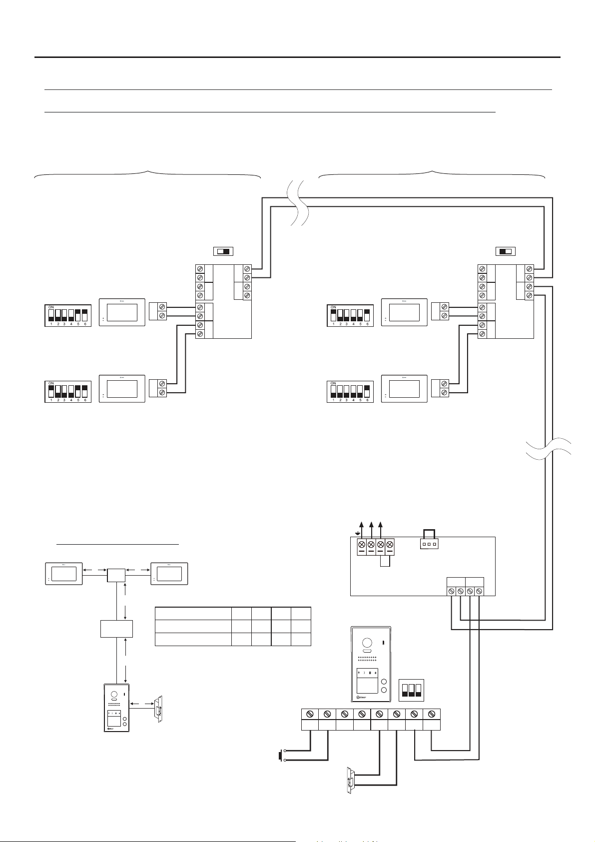
Two apartments with 4 PENTHA monitors, 2 DP-GB2A distributors and Golmar DC lock release.
NOTE: Up to 4 Pentha monitors per installation.
APARTMENT 2 APARTMENT 1
19
CODE 16
**
CODE 17
**
Configur the end of line in the last distributor.e
*
Switch to ON.
Configure the end of line in the last monitor.
**
DIP 6 to ON.
Distances and cross-sections:
DP-GB2A
C
C
BUS
BUS
PENTHAPENTHA
End of line
*
BUS BUS
D
C
B
A
End of line
ON
BUS
BUS
**
CODE 1
DP- 2GB A
CODE 0
**
PENTHAPENTHA
BUS
PENTHAPENTHA
BUS
OFF
BUS BUS
D
BUS
C
BUS
B
DP- 2GB A
A
Mains
100~240Vac
N L
L
CN
FA- 2GB /A
BUS (M) BUS(PL)
B
C
D
10m
15m
Access panel
FA- 2GB /A
A
Cable
Twisted pair 2x0.75mm
Twisted pair 2x1mm
( )2
( )2
Distances with Golmar RAP-2150 cable
(twisted pair 2x1mm ).
2
6 m0A55mB30m
2
65m 60m 30m
2
D
AP-
AP+
AP
Lock release
max. 12 Vdc/270mA.
(1)
Important: For AC lock release, 2nd AC lock release or automatic gate, see wiring diagrams p. 22.
NA1
C1
CV- BUSBUS
( )1
( )1
CV+
SW1
ON
1 2 3
Page 20

JAZZ GB2 VIDEO DOOR ENTRY SYSTEM KIT - HOUSE
WIRING DIAGRAMS:
Two apartments with 4 PENTHA monitors, 2 D2L-GB2 distributors and Golmar DC lock release.
NOTE: Up to 4 Pentha monitors per installation.
APARTMENT 2 APARTMENT 1
20
CODE 16
**
BUS
CODE 17
**
BUS
(1)
Set thejumper in this position for 7” GB2 monitors of
all of theD2L-GB2 distributors.
Remove the jumper from all of the distributors
*
except the last.
Configure the endof line in the lastmonitor.
**
DIP 6 to ON.
Distances and cross-sections:
D -2L GB2
C
PENTHAPENTHA
C
B
FA- 2GB /A
A
Twisted pair 2x0.75mm
Twisted pair 2x1mm
( )3
( )3
Distances with Golmar RAP-2150 cable
(twisted pair 2x1mm ).
(1)
Cable
BUS BUS
*
of line
ON
D2
D1
D2L-GB2
2
2
End
BUS
BUS
C
6 m0A55mB30m
65m 60m 30m
2
D
10m
15m
**
**
CODE 1
CODE 0
PENTHAPENTHA
PENTHAPENTHA
Mains
100~240Vac
N L
L
Access panel
BUS
BUS
CN
FA- 2GB /A
(1)
BUS (M) BUS(PL)
BUS BUS
End
of line
OFF
D2
BUS
D1
BUS
D2L-GB2
D
AP-
AP+
AP
Lock release
max. 12 Vdc/270mA.
( )2
Important: For AC lock release, 2nd AC lock release or automatic gate, see wiring diagrams p. 22.
NA1
C1
CV- BUSBUS
( )2
( )2
CV+
SW1
ON
1 2 3
Page 21

JAZZ GB2 VIDEO DOOR ENTRY SYSTEM KIT - HOUSE
WIRING DIAGRAMS:
Video door entry system with 4 access panels, DP-GB2A distributor for door panels and Golmar DC lock
release.
Mains
100~240Vac
N L
L
House with distributors (up to 4 Pentha monitors per installation)
House without distributors (up to 4 Pentha monitors per installation)
CN
FA- 2GB /A
BUS (M) BUS(PL)
21
SW1
ON
1 2 3
AP+
AP
Lock release
max. 12 Vdc/270mA.
AP-
( )
*
BUS BUS
End of line
OFF
BUSBUS
DP- 2GB A
D C B A
( )
Important: (in this distributor).
*
House with distributors (up to 4 monitors):
Leave the end of line in the OFF position.
House without distributors (up to 4 monitors):
Set the end of line to ON.
Access panel 3Access panel 4
or
NA1
C1
( )1
( )1
CV+
CV- BUSBUS
SW1
ON
1 2 3
AP+
AP
Lock release
max. 12 Vdc/270mA.
AP-
or
NA1
C1
( )1
( )1
CV+
CV- BUSBUS
SW1
ON
1 2 3
AP-
AP+
AP
Lock release
max. 12 Vdc/270mA.
(1)
Important: For AC lock release, 2nd AC lock release or automatic gate, see wiring diagrams p. 22.
ór
NA1
C1
( )1
( )1
CV+
CV- BUSBUS
SW1
ON
1 2 3
AP+
AP
Lock release
max. 12 Vdc/270mA.
AP-
Access panel 2Access panel 1
or
NA1
C1
( )1
( )1
CV+
CV- BUSBUS
Page 22

JAZZ GB2 VIDEO DOOR ENTRY SYSTEM KIT - HOUSE
WIRING DIAGRAMS:
Connection of one Golmar AC lock release.
Access panel
22
To the FA-GB2/A
power supply
TF-104
NC NA C
SAR- 21 /24
PRI
SEC
~
~
~
~
( )
Lock release
max. 12 Vca/850mA.
( )
Important: Fit the varistor supplied with the kit directly to the terminals of the lock release.
*
*
230Vca
IN IN
AP
SW1
ON
1 2 3
AP+
Connection of 2nd Golmar AC lock release.
Access panel
TF-104
PRI
~
~
SEC
~
~
SW1
ON
1 2 3
AP+
AP-
C1
NA1
or
AP-
C1
NA1
CV- BUSBUS
or
CV- BUSBUS
CV+
CV+
To the FA-GB2/A
power supply
( )
Lock release
max. 12 Vca/850mA.
( )
Important: Fit the varistor supplied with the kit directly to the terminals of the lock release.
*
*
230Vca
AP
Connection to an automatic gate.
Access panel
SW1
ON
1 2 3
AP-
( )
AP+
AP
*
C1
NA1
or
CV- BUSBUS
CV+
Lock release
max. 12 Vdc/270mA.
To the FA-GB2/A
power supply
Lock release
max. 12 Vdc/270mA.
( )
- To switch voltages higher than 12Vdc/1A between terminals 'C1' and 'NA1' on the door panel, consult our technical support service.
*
- .'C1' and 'NA1' potential-free contact
Page 23

JAZZ GB2 VIDEO DOOR ENTRY SYSTEM KIT - HOUSE
NOTES:
23
 Loading...