

Page 1

SERIES
Status Monitoring
Installation and Technical Manual
DOCSIS® HMS Embedded Transponder
Effective: December , 2004
Alpha Technologies
®
Page 2

Alpha Technologies
Power
®
2
745-420-C0-002 Rev. B
Page 3

DOCSIS® HMS Embedded T ransponder
Installation and Technical Manual
745-420-C0-002, Rev . B
Effective Date: December, 2004
Copyright© 2004
Alpha Technologies, Inc.
A Member of the Alpha Group
Alpha denies responsibility for any damage or injury involving its enclosures, power supplies, generators,
batteries or other hardware, manufactured by Alpha or members of the Alpha Group, when used for an
unintended purpose, installed or operated in an unapproved manner , or improperly maintained.
Photographs and drawings contained in this manual are only for illustrative purposes. These photographs and
drawings my not exactly match your installation.
Review the written and illustrative information contained in this manual before proceeding. If there are questions
regarding the safe installation or operation of this product, please contact Alpha Technologies or your nearest
Alpha representative.
Contacting Alpha Technologies: www.alpha.com
OR
For general product information and customer service (7 AM to 5 PM, Pacific Time), call
1-800-863-3930
For complete technical support, call
1-800-863-3364
745-420-C0-002 Rev . B
7 AM to 5 PM, Pacific Time or 24/7 emergency support
DOCSIS® is a Registered Trademark of CableLabs.
3
Page 4

T able of Contents
Safety Notes ......................................................................................................................... 6
1.0 Introduction to the DOCSIS Transponder .................................................................... 7
1.1 System Overview............................................................................................. 8
1.2 LED Indicators............................................................................................... 10
2.0 Transponder Installation............................................................................................ 11
2.1 Provisioning the T ransponder ........................................................................ 11
2.1.1 Network Connectivity .......................................................................... 11
2.1.2 Transponder Configuration File ........................................................... 1 2
2.2 V erifying Software V ersion and Device Address ............................................ 13
2.3 Installing the T ransponder Hardware .............................................................. 13
2.4 RF Connection .............................................................................................. 15
2.5 V erifying Transponder Operation.................................................................... 15
3.0 Network/Element Management Software .................................................................. 16
3.1 Provisioning the SNMP Manager................................................................... 16
3.2 Transponder Acquisition by the SNMP Manager ............................................ 16
4.0 Local Port................................................................................................................. 17
5.0 Specifications........................................................................................................... 19
6.0 Acronym Definitions ................................................................................................. 20
4
745-420-C0-002 Rev. B
Page 5

List of Figures
Fig. 1-1, DOCSIS Embedded Transponder with EDSM......................................................... 7
Fig. 1-2, System Interconnection Diagram 1 .......................................................................... 8
Fig. 1-3, System Interconnection Diagram 2 .......................................................................... 9
Fig. 2-1, Attaching the10-pin Connector............................................................................... 14
Fig. 2-2, Att aching the PCB Standoff ................................................................................... 14
Fig. 2-3, Transponder Components..................................................................................... 14
Fig. 2-4, RF Connection with Ground Block ......................................................................... 15
Fig. 4-1, Local Port to PC Connection ................................................................................. 17
745-420-C0-002 Rev . B
5
Page 6

Safety Notes
Review the drawings and illustrations contained in this manual before proceeding. If there are any questions
regarding the safe installation or operation of the system, contact Alpha Technologies or the nearest Alpha
representative. Save this document for future reference.
T o reduce the risk of injury or death and to ensure the continued safe operation of this product, the following
symbols have been placed throughout this manual. Where these symbols appear, use extra care and
attention.
The use of A TTENTION indicates specific regulatory/code requirement s that may affect the placement of
equipment and /or installation procedures.
A NOTE provide additional information to help complete a specific task or procedure.
The use of CAUTION indicates safety information intended to PREVENT DAMAGE to material or
equipment.
WARNING presents safety information to PREVENT INJURY OR DEA TH to the technician or
user.
6
745-420-C0-002 Rev. B
Page 7
1.0 Introduction to the DOCSIS Transponder
The DOCSIS Digital Embedded Transponder for the XM2 power supply manages network powering
through existing cable modem or high speed data infrastructure. A single transponder can monitor and
manage multiple power supplies, multiple strings of batteries, and one generator . The transponder
transmits data to a management system via the existing DOCSIS network. SNMP (Simple Network
Management Protocol) keeps bandwidth use to a minimum. S tatus monitoring dat a is compatible with
ANSI/SCTE HMS (Hybrid Management Sublayer) standards.
With optional V oIP test functionality , the power supply transponder becomes a powerful network
diagnostics tool. Contact Alpha Technologies for more information.
Outstanding Features:
• Uses existing headend DOCSIS CMTS equipment.
• Uses ANSI/SCTE HMS st andards.
• Single transponder supports up to six power supplies, two battery strings, and one generator .
• Additional battery strings (up to a total of six) can be monitored with Alpha’s extended MIBs.
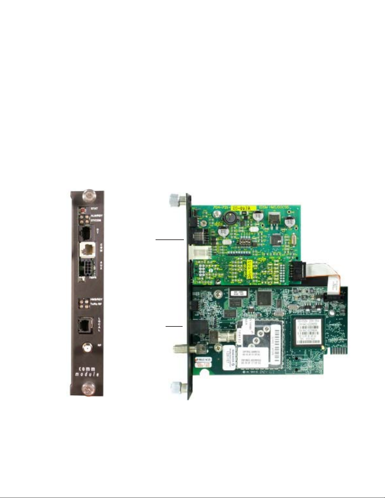
EDSM
DOCSIS HMS Embedded
Transponder
Fig. 1-1, DOCSIS Embedded Transponder with EDSM
745-420-C0-002 Rev . B
7
Page 8

1.0 Introduction to the DOCSIS Transponder, continued
1.1 System Overview
The DOCSIS Digital T ransponder obtains data from the EDSM (Enhanced Digital S tatus
Monitoring) interface card through an XM2 Power Supply . The EDSM collects data directly from
the battery strings or from the AlphaBus Communications Network, depending on system
configuration.
Equipment monitored (direct battery monitoring):
• An XM2 Power Supply
• One or two 36VDC or 48VDC battery strings
• One AlphaGen st ationary generator system (if installed)
Generator (ECM)
Tamper
Switch
XM2
Dashed lines indicate
wiring for 48V strings
4A
H
M
S
C
O
M
Battery
Sense
24V 12V
48V
4B
36V
2B
3B
1B
Battery Wire Sense
Harness
Battery
RF
RF Cable
Sense
48V
24V 12V
36V
36/48V
Battery Pack
36/48V
Battery Pack
2A 1A
3A
Network
Fig. 1-2, System Interconnection Diagram 1
8
745-420-C0-002 Rev. B
Page 9

1.0 Introduction to the DOCSIS Transponder, continued
1.1 System Overview, continued
Equipment monitored (via AlphaGuard):
• A primary XM2 Power Supply (via an internal network connection).
• Up to five additional XM2 Power Supplies equipped with Serial Interface (SI) cards.
• One or two 36VDC or 48VDC battery strings with AlphaGuard CMM Battery Monitors
• Up to four additional AlphaGuards with extended CMM modules
• One AlphaGen st ationary generator system (if installed)
Generator (ECM) XM2 XM2 XM2
S
Y
S
C
O
M
AlphaGuard
CMM
1234
AlphaGuard
CMM
1234
S
Y
S
C
O
M
Battery
Sense
Battery
Sense
"Master"
XM2
S
Y
S
C
O
M
H
M
S
C
O
M
Tamper
Switch
RF
RF Cable
Network
2A
3A
1A
36/48V
Bat tery Pa ck
24V 12V
36V
2B
3B
1B
36/48V
Bat tery Pa ck
24V 12V
36V
745-420-C0-002 Rev . B
AlphaGuard
CMM
3C
1234
Battery
Sense
36V
Fig. 1-3, System Interconnection Diagram 2
2C
24V 12V
1C
36/48V
Bat tery Pa ck
9
Page 10

1.0 Introduction to the DOCSIS Transponder, continued
1.2 LED Indicators
HMS: Indicates status of serial communications between
transponder and EDSM
OFF: No communications
OFF flickering ON: Communicating with EDSM
RDY: Indicates status of transponder
OFF: No power to transponder from EDSM, or
malfunctioning transponder.
ON: Transponder reset in progress
Flashing ON & OFF: Normal operation
RX: Indicates status of link with CMTS
OFF: No communication with CMTS
ON flickering OFF: Receiving data, CMTS link established
OFF flickering ON: Receiving data, CMTS link failed
Flashing ON & OFF: Failed communications
TX: For future use
10
745-420-C0-002 Rev. B
Page 11

2.0 Transponder Installation
Steps to a Successful Installation:
• Operator’s IT Department must allow the transponders’ Cable Modem (CM) to obtain an IP address
from the DHCP Server.
• Operator’s IT Department must load the HMSINIT.ini file on the TFTP Server .
• Operator’s network security policies must allow SNMP traffic to pass between transponder and
SNMP manager .
• Install the transponder and any related equipment in the power supply .
• Connect an RF drop.
• Verify proper operation.
2.1 Provisioning the Transponder
Complete Sections 2.1.1 and 2.1.2 before connecting the transponder to the RF network.
Otherwise, you must reset each transponder.
2.1.1 Network Connectivity
The transponder’s CM must be recognized by the CMTS as a valid device. The CM
must obtain an IP address from the DHCP server, locate the TFTP and T OD servers,
and communicate with the SNMP management server (trap receiver). CMTS and
system vendors use different security methods to insure network integrity , but some
common issues are:
• A “subscriber account” (where the subscriber is the transponder) may be required
for each transponder.
• The transponder’s MAC address may have to be pre-loaded into the CMTS.
• MAC filtering may have to be modified to allow MAC addresses starting with
00:10:3f:xx:xx:xx to be registered.
• For SNMP access, UDP ports 161 & 162 must not be blocked.
• Firewalls must allow communication between the CM and the TFTP, DHCP, SNMP,
and TOD servers.
• If the address of the TFTP and/or TOD server is different than the DHCP server , the
response from the DHCP server must contain the TFTP and TOD addresses.
745-420-C0-002 Rev . B
11
Page 12

2.0 Transponder Installation, continued
2.1 Provisioning the Transponder, continued
2.1.2 Transponder Configuration File
The transponder’s CM, at first power-up or reset command, requests a configuration file
from the TFTP server . The file must contain the IP address of the SNMP manager. It
may also contain up to five additional SNMP trap recipients. The SNMP manager will
be the only device that can perform SNMP set/get/get-next commands. The trap
recipients and SNMP manager receive the same traps generated by the transponder .
• File type: ASCII text file
• File name: HMSINIT.ini
• File location: Root directory of the TFTP server
• Maximum file size: 4096 bytes (4Kb)
• File format:
// IP address of the SNMP manager
[SERVER IP]
10.1.1.5
// IP address of up to 5 additional trap receivers
[TRAP SERVER IP]
10.1.1.6
10.1.1.7
• The “//” characters indicate an optional comment line.
• The identifiers must be in all caps, and enclosed by brackets “[ ]”.
• The IP addresses must appear on the next line after the identifier , one address per
line. Replace the IP addresses in this example with the actual addresses used in
the network.
• The trap server IP identifier is optional. Addresses for up to five trap recipients can
be listed.
12
745-420-C0-002 Rev. B
Page 13

2.0 Transponder Installation, continued
2.2 Verifying Software Version and Device Address
Before removing the Inverter Module (IM), verify the power supply software version and device
address are correct.
• IM firmware v3.00.0 is the minimum version compatible with the DOCSIS Embedded
Transponder .
• The power supply device address must not be set to zero, and no two power supplies
monitored by a single transponder may have the same address.
1. Press the Enter key on the inverter module twice to access the SETUP Menu.
2. Press the Down key until CODE VER is displayed.
3. V erify that the software code is 3.00.0 or higher .
4. Press the Down key twice until DEVICE ADDRESS is displayed.
5. If the address is correct (and not zero), skip to S tep 10.
6. To change the address, press the Enter key to enter the Edit mode.
7. Press the Up or Down key until the desired address (between 1 and 7) is displayed.
Remember that each power supply on a single transponder must have a unique address.
8. Press the Enter key to load the new address.
9. Press the Enter key again to accept the new data.
10. Press ESC three times to return to the OPERATION NORMAL screen.
2.3 Installing the Transponder Hardware
The following installation procedure assumes the EDSM card, AlphaGuard CMM data collection
module and AlphaBus network have already been inst alled. If not, see the EDSM Installation
and T echnical manual (P/N 704-721-C0) for further instructions.
The Embedded Transponder is static sensitive. An ESD wrist strap should be worn when installing
the transponder .
T ools Required: #1 Phillips Screwdriver
1. Move the XM2 Battery Breaker to the OFF position.
2. Unplug all connections to the front of the Inverter Module (battery cable, RTS, etc).
3. Loosen the thumbscrews holding the Inverter Module into the power supply . Slide the
Inverter Module out just enough to disconnect the ribbon cable. Now slide the Inverter
Module out of the power supply .
T o reduce the risk of electric shock, completely remove the Inverter Module from the Power
Supply prior to installation.
745-420-C0-002 Rev . B
13
Page 14

2.0 Transponder Installation, continued
2.3 Installing the Transponder Hardware, continued
4. Attach the new transponder ribbon cable supplied to the 10-pin connector on the
transponder as shown in Fig. 2-1. The connectors are keyed to prevent incorrect
orientation.
5. Attach the plastic standoff to the transponder PC board as shown in Fig 2-2.
6. V erify that the MAC address label is installed on the transponder. If the label is missing,
locate the label in the packaging and apply to the transponder as shown in Fig 2-3.
7. Place the transponder as shown in Fig 2-3 below . The RF connector must be inserted
through the front of the Comm Module bracket.
8. Press the standoff into the Inverter Module chassis.
9. Secure the transponder to the Comm Module Bracket with the two screws provided.
10. Connect the transponder ribbon cable to the EDSM. Note the 90o twist in the cable.
1 1. Reconnect the Inverter Module ribbon cable, and reinstall the Inverter Module into the power
supply.
12. Reconnect all the cables unplugged in Step 2 .
13. Move the Battery Breaker to the ON position.
10-pin Connector
Fig. 2-1, Attaching the10-pin Connector
PCB Standof f
Fig. 2-2, Attaching the PCB St andoff
Ribbon Cable
EDSM
PCB Standof f
DOCSIS
Securing Screws
RF Connector
Comm Module Bracket
14
MAC Address Label
Fig. 2-3, Transponder Components
745-420-C0-002 Rev. B
Page 15

2.0 Transponder Installation, continued
2.4 RF Connection
Connect the RF drop to the face of the transponder . The drop must have a properly installed
ground block in or on the power supply enclosure. Recommended forward RF level is 0 dBmV .
Battery
Breaker
Batter y
Input
Temp
Probe
LOCAL
RF
RF Connection
Ground Surge
RF Cable
to Headend
Protector
See Caution Below
User Provided
Fig. 2-4, RF Connection with Ground Block
Alpha requires installing a grounded surge suppressor (Alpha P/N 162-028-10 or equivalent).
2.5 Verifying Transponder Operation
745-420-C0-002 Rev . B
During initial transponder power-up, the RDY LED will be on solid.
• Once the reset is complete, the RDY LED will flash at a ½ sec ON, ½ sec OFF rate.
• The RX LED will now be ON, flickering OFF occasionally , indicating a link with the CMTS
has been established.
• The HMS LED will occasionally flicker ON, indicating communication with the EDSM.
15
Page 16

3.0 Network/Element Management Software
3.1 Provisioning the SNMP Manager
The following MIB (Management Information Base) files are required for the SNMP Manager to
collect data from the transponders. These files can be found on the Society of Cable
T elecommunications (SCTE) web site
so they should be compiled in the following order listed below:
ANSI/SCTE 36 2002 (formerly HMS 028), SCTE-ROOT Management Information Base (MIB)
Definitions
ANSI/SCTE 37 2003 (formerly HMS 072), Hybrid Fiber/Coax Outside Plant S tatus Monitoring
SCTE-HMS-ROOTS Management Information Base (MIB) Definition
ANSI/SCTE 38-1 2002 (formerly HMS 026), Hybrid Fiber/Coax Outside Plant S tatus Monitoring
SCTE-HMS-PROPERTY -MIB Management Information Base (MIB) Definition
ANSI/SCTE 38-2 2002 (formerly HMS 023), Hybrid Fiber/Coax Outside Plant S tatus Monitoring
SCTE-HMS-ALARMS-MIB Management Information Base (MIB) Definition
ANSI/SCTE 38-3 2002 (formerly HMS 024), Hybrid Fiber/Coax Outside Plant S tatus Monitoring
SCTE-HMS-COMMON-MIB Management Information Base (MIB) Definition
ANSI/SCTE 38-4 2002 (formerly HMS 027), Hybrid Fiber/Coax Outside Plant S tatus Monitoring
SCTE-HMS-PS-MIB Management Information Base (MIB) Definition
ANSI/SCTE 38-6 2003 (formerly HMS 033) Hybrid Fiber/Coax Outside Plant St atus Monitoring SCTE-HMS-GEN-MIB Management Information Base (MIB) Definition
ANSI/SCTE 38-7 2002 (formerly HMS 050), Hybrid Fiber/Coax Outside Plant S tatus Monitoring
SCTE-HMS-Transponder-Interface-Bus(TIB)-MIB Management Information Base (MIB) Definition
www .scte.org. These are dependencies between MIB files
3.2 Transponder Acquisition by the SNMP Manager
The transponder must first complete its initialization/registration and retrieve the .ini file from
the TFTP server . The transponder will then send a warm-start trap to the SNMP Manager
(specified as the Server IP in the .ini file). This trap provides the SNMP Manager with the
MAC and IP addresses of the transponder and should, depending on the configuration of the
manager software, initiate monitoring of the power supply system.
16
745-420-C0-002 Rev. B
Page 17

4.0 Local Port
The local port allows the technician to communicate with the transponder and power supply through a
PC’s RS-232C serial port.
1. Connect the optional Local Port to RS-232C Adaptor Cable (Alpha P/N 875-349-10) between the
transponder’s Local Port and the computer’s serial port. Launch the computer’s Terminal Emulation
Software (HyperT erminal is recommended).
Fig. 4-1, Local Port to PC Connection
2. Communication settings are:
• 19,200 baud
• 8 data bits
• No parity bit
• 1 stop bit
• No flow control
3. Press ENTER to initiate communications.
4. Press “?” and ENTER to display the menu:
Battery
Breaker
Battery
LOCAL
Local port
Input
Temp
Probe
RF
Logic Level
Alpha P/N 875- 349-10
RS-232
Converter
Laptop Computer
port
With
HyperTerminal
(19,200,8,N, 1)
745-420-C0-002 Rev . B
HELP - This help
? - This help
RESET - Reset transponder
ST ATUS - Transponder config and status
ALARMS - Display active alarms
I D - Enter logical ID
PSDA TA - Display power supply data
DEVICE - Display device status
PSTEST - Initiate power supply test
GENDATA - Display generator data
GENTEST - Initiate generator test
GENRESET - Reset generator alarms
17
Page 18

4.0 Local Port, continued
Enter a command, and press ENTER. If there is more than one power supply connected to the
transponder , then PSDATA and PSTEST must be followed by the device address number .
Verify communications between the power supply , EDSM and transponder with the PSDA TA command.
The data returned should match the data of the power supply display .
MAC Address: 00-10-3F-00-00-0D
Serial No: 123450000
Version: 1.0.2.L 1600 950-0315 A 05.00
IP Address: 192.168.1.102
Check code: 0x0000
CommonNEStatus: 0x19
(actual data will be different)
18
745-420-C0-002 Rev. B
Page 19

5.0 Specifications
DOCSIS® Network Power Monitoring
General Specifications
General
Power Supplies Supported: XM2, XM2VP
DOCSIS Compatibility: DOCSIS 1.1
Monitoring Protocol: SNMPv1
Devices Monitored: Power Supply, Batteries and Generator
Hardware
RF Cable Interface: F-connector, female, 75ohm
Local Interface: RJ-12, RS-232, 19.2kb,N,8,1
LED Indicators: Transponder Ready; HMS CommuniEnvironmental: -40ºC to +65ºC
Emissions: EN50022 Class A and FCC Part 15 Class
Warranty: 2 years
RF Transmit / Receive
Tx Frequency Range: 5 to 42 MHz
Output Power: +8 to +58 dBmV
Channel Bandwidth: 6 MHz
Receive Center Freq Range: 91 to 857 MHz (Standard, HRC, IRC
Input Level: -15 to +15 dBmV
Monitored Parameters
Number of Power Supplies: Up to six, each reporting individual data
Power Supply Data: Major Alarm (includes: test fail, battery fail,
Power Supply Control: Remote test start/stop
Number of Battery String: One or Two Strings of 36V or 48V
Battery Data: Individual Battery Voltages
Generator Data: Status (off, running, alarm)
Generator Control: Remote test (start/stop)
compatible with ANSI/SCTE 25-3 2002,
(formerly HMS 022)
Requires serial port adapter and with
terminal emulation software (Hyper-
T erminal recommended)
cations; RF Transmit; RF Receive
10 to 90% non-condensing humidity
A (Installed in power supply enclosure system)
channels)
line isolation, output over load/fault, over
temp, N+1 active, fuse fail)
Minor Alarm (includes: temp probe error, AC
line loss, N+1 error)
Input AC Line Voltage
Output Voltage
Output Current 1
Output Current 2,3,4 (if installed)
Output Power
Power Supply Status (line, standby, test in
progress, test alarm)
Enclosure Door (open/closed)
Additional battery string monitoring available.
Call Alpha for more information.
Battery Compartment Temperature
(Alarm includes: low oil pressure, engine overtemp, engine over-speed, crank limit, overvoltage, low fuel, water intrusion, pad shear,
gas hazard, test fail)
Gas hazard
Water Intrusion
Pad Shear
Enclosure Door (open/closed)
Ignition Battery Voltage
Enclosure Temperature
Low Fuel
Ordering Information
EDSM-IDH2 DOCSIS Monitoring
DCS-XM2V-2 (XM2VP) Includes: transponder with VoIP test
IDH2 DOCSIS Embedded XM2 Transponder
875-349-10 Local port adaptor
875-155-20 10-pin Connector
Battery Sense Wire Kits
874-842-21 1x36V, 6 ft
874-842-20 2x36V, 6 ft
874-842-27 1x36V, 9 ft
874-842-28 2x36V, 9 ft
874-841-21 1x48V, 6 ft
874-841-20 2x48V, 6 ft
874-841-25 1x48V, 9 ft
874-841-24 2x48V, 9 ft
Extended wire lengths available. Contact Alpha for ordering information.
SI-XM2-KIT (XM2) Additional XM2 Interface Kit
SI-XM2V-KIT (XM2VP) Includes SI adaptor and integration kit
function, EDSM and bracket. Order
AlphaGuard Battery Management or wire
sense kit separately.
with VoIP Test Function( For installation
with existing EDSM. Order AlphaGuard
Battery Management or wire sense kit
separately.
for connecting an additional power
supply for monitoring. One kit required
for each additional power supply (up to
six total).
Management
NMS/EMS: Cheetah™ DOCSIS
HMS MIBs: Power Supply (ANSI/SCTE 38-4)
745-420-C0-002 Rev . B
®
Management Software
Standard SNMP Management T ools
Generator (ANSI/SCTE 38-6)
Transponder (ANSI/SCTE 38-3)
Alarm/Trap (ANSI/SCTE 38-1 and 38-2)
Power Supply
19
Page 20

6.0 Acronym Definitions
ANSI: American National Standards Institute
CM: Cable Modem
CMTS: Cable Modem T ermination System
DHCP: Dynamic Host Configuration Protocol
DOCSIS: Data Over Cable Service Interface S pecification
EDSM: Enhanced Digital Status Module
EMS: Element Management System
IT : Information Technology
MAC: Media Access Control
MIB: Management Information Base
NMS: Network Management System
QoS: Quality of Service
SCTE-HMS: Society of Cable Telecommunications Engineers-Hybrid Management Sublayer
SI: Serial Interface
SNMP: Simple Network Management Protocol
TFTP: Trivial File Transfer Protocol
TOD: Time of Day
UDP: User Datagram Protocol
VoIP: Voice over Internet Protocol
20
745-420-C0-002 Rev. B
Page 21

Alpha Technologies
Power
®
Alpha T echnologies
3767 Alpha Way
Bellingham, WA 98226
USA
T el: +1(360) 647-2360
Fax: +1(360) 671-4936
Web: www.alpha.com
Alpha T echnologies Ltd.
4084 McConnell Court
Burnaby, BC, V5A 3N7
CANADA
T el: +1(604) 430-1476
Fax: +1(604) 430-8908
Alpha T echnologies
Europe Ltd.
Cartel Business Estate
Edinburgh Way
Harlow, Essex CM20 2TT
UNITED KINGDOM
Tel: +44-1279-4221 10
Fax: +44-1279-423355
Alpha T echnologies
Hansastrasse 8
D-91126 Schwabach
GERMANY
T el: +49-9122-79889-0
Fax: +49-9122-79889-21
Alphatec, Ltd
P .O. Box 56468
Limassol, Cyprus
CYPRUS
T el: +357-25-375675
Fax: +357-25-359595
Alpha T echnologies
5 Avenue Victor Hugo
F-92140 Calmart France
FRANCE
T el: +33-3-41-90-07-07
Fax: +33-1-41-90-93-12
Copyright © 2004 Alpha T echnologies, Inc. All rights reserved. Alpha is a registered trademark of Alpha Technologies. 745-420-C0-002 Rev. B.
Due to continuing product improvements, Alpha reserves the right to change specifications without notice.
 Loading...