

Page 1

Chapter F
Ring Communications Inc.
Digital Network Bridge
DNB100
RING COMMUNICATIONS INC.
Page 2

RING COMMUNICATIONS INC.
Page 3

September 2004 DIGITAL NETWORK BRIDGE DNB100
CHAPTER F
TABLE OF CONTENTS
DNB100 DIGITAL NETWORK BRIDGE ........................................... F5
INTRODUCTION ....................................................... F5
OPERATIONAL DESCRIPTION ............................................ F5
INSTALLATION ........................................................ F5
Network connections .............................................. F6
RS232 signals ................................................... F7
RS422 signals ................................................... F8
Setting Baud Rate ................................................ F9
Setting Network and Device Address ................................. F9
Communication Protocols .......................................... F9
FRONT PANEL SWITCHES AND INDICATORS ............................... F10
F3RING COMMUNICATIONS INC.
Page 4

RING COMMUNICATIONS INC.
Page 5

September 2004 DIGITAL NETWORK BRIDGE DNB100
DNB100 DIGITAL NETWORK BRIDGE
INTRODUCTION
The Digital Network Bridge (DNB100) interfaces two Ring-Master Crisis Alert Networks to each
other. One DNB100 is required in each network.
OPERATIONAL DESCRIPTION
The DNB100 is installed on a network using a RJ45, eight conductor, modular connector to connect
to the RS485 data pair and the +24 Volt DC power. The two DNB100's are "bridged" using a RS232
or RS422 connection between them.
Maximum distance with RS232 is 15 M (50 feet)
Maximum distance with RS422 is 3 KM (10,000feet).
The address of the DNB100 is set on DIP Switch SW2. The network address is the same as the
network it is attached to, and the node number must always be zero.
The DNB100 can be reset by pressing SW1.
The DNB100 has eight LED's for indication of operation and trouble shooting. See Figure F3 and
description on page F10.
When a data packet on a network contains a destination address not on this network the DNB100
takes the data packet and transfers it through an RS232RS422 port to the DNB100 on the other
network. The DNB100 on the second network re-transmits the data on its RS485 network.
Use BF640A cord to connect the DNB100 to the RJ45 network jack, KB171.
Use BF961 cord to connect the DNB100 to the RS422 jack,KB161.
Cords and jacks must be ordered separately.
Bridge mode:
The DNB100 may connect two networks with different network number.
This will increase the total number of nodes from 8 to 16.
Bridges may be interconnected using copper, fiber optic cable drivers, radio or data multiplexers.
Only one Bridge(DXB901 or DNB100) may be in bridge mode on a network.
The DNB100 does not use a node position.
Extender mode:
The DNB100 may connect two networks with the same network number.
Bridges may be interconnected using copper, fiber optic cable drivers, radio or data multiplexers.
Multiple DNB100 can be connected in extender mode to a network.
The DNB100 does not use a node position.
F5RING COMMUNICATIONS INC.
Page 6

September 2004 DIGITAL NETWORK BRIDGE DNB100
INSTALLATION
Each DNB100 in a system can be individually powered from a fuse in the CB901/RM5000 or a local
power supply operating off 24V regulated DC.
Figure F1 - Rear Panel Connectors
J1 - 8 pin (RJ45) Network connections :
Two modular jacks are provided at the rear of the DNB100. See Figure F1. Use modular cables
with straight through pin configuration only! An 8-pin (RJ45) modular jack (KB171) and cord
(BF640A) are required for connection to the network.
PIN# - DESIGNATION
1 - No connection.
2 - +12 VDC power input
3 - Data + (positive)
4 - No connection.
5 - No connection.
6 - Data - (negative)
7 - -12 VDC power input
8 - Not used.
F6 RING COMMUNICATIONS INC.
Page 7

September 2004 DIGITAL NETWORK BRIDGE DNB100
J2 - 9 pin (DB9) RS232 signals :
A null-modem (LapLink) cable can be used to connect two DNB100's together if the DNB100's are
close enough to each other. Two modems for leased line operation can be used to increase the
distance between two bridges.
If you are going to make your own cable the following is a description of the pinouts of the DB9
connector on the DNB100. The RS232 cable should not exceed 50 feet in length.
J2 SIGNAL
DIRECTION/
PIN# NAME DESIGNATION
1 DCD
Data Carrier Detect, input.
2 RXD Receive Data, input.
3 TXD Transmit Data, output.
4 DTR
Data Terminal Ready, output.
5 GND Signal Ground.
6 DSR
Not used.
7 RTS Request to Send, output.
8 CTS
Clear to Send, input.
9 RI Not connection.
F7RING COMMUNICATIONS INC.
Page 8
September 2004 DIGITAL NETWORK BRIDGE DNB100
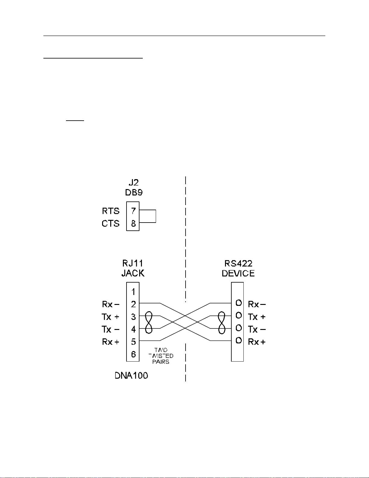
J3 - 6 pin (RJ11) RS422 signals :
A two twisted pair installation utilizing RS422 signals can be used to connect two bridges up to 7000
feet apart.
Use a six wire RJ11 cord (BF961) with straight through wiring from J3 to a RJ11 jack (KB161).
Use two twisted pairs between the two RJ11 jacks as shown in Figure F2.
A strap MUST be installed between RTS and CTS of J2 (DB9), in order to disable flow control for
the RS422. To do this, simply place a strap between pin 7 and pin 8 of J2. You could also solder
this strap to a female DB9 connector with solder lugs on the rear, then insert it into the J2 connector.
Figure F2 illustrates the strapping of J2.
Figure F2 - RS422 Bridge Interconnection
F8 RING COMMUNICATIONS INC.
Page 9

September 2004 DIGITAL NETWORK BRIDGE DNB100
Setting Baud Rate
DIP switch SW3-1 through SW3-6 is used to set the desired baud rate for the RS232 data. See
Figure F3. SW3-7 and SW3-8 are not used and should be left in the off, 0, position for normal
operation. The network operates at 9600 baud and the RS232 data channel should also be set at
9600. Slower baud rates can be used when using modems, but may decrease network efficiency
and speed.
BAUD
RATE
19200 1 0 0 0 0 1 0 = off
9600 1 0 0 0 1 0 1 = on
4800 0 1 0 0 0 1
2400 0 1 0 0 1 0
1200 1 0 0 0 1 1
Setting Network and Device Address
DIP switch SW2 is used to set the address of the device. SW2-1 through SW2-3 sets the node
address. The node address for the DNB100 must be zero. SW2-4 through SW2-8 sets the network
address which must match the network that it is attached to. See SETTING NETWORK ADDRESS of
Chapter A -NETWORK for a full description for setting addresses, as well as, an addressing chart.
1 2 3 4 5 6
SW3
NOTE
If any DIP switches are changed while the DNB100 is operating,
it must be RESET or powered off and then on, in order for the
changes to become valid.
Communication Protocol
1 Start Bit, 8 Data Bits, Even Parity and 1 Stop Bit.
F9RING COMMUNICATIONS INC.
Page 10

September 2004 DIGITAL NETWORK BRIDGE DNB100
FRONT PANEL SWITCHES AND INDICATORS - Figure F3
SWITCHES
SW1 -
Reset. Creates a local reset for this node only.
SW2 - Node & Network Address
SW3 -
RS232 Baud Rate, Device selection
L.E.D.'s (left side, network)
RUN - Indicates the local processor in the DNB100 is running. Will illuminate after power up
or reset.
MASTER - Will light steady if this node is the master on the network. There can only be one master
on each network. On power up, each device waits for a response from a master. If no
response is received, then this device will take over as a master. Therefore, the first
device powered up will be the master.
TX -
Transmit data to the Network. Will flash when the DNB100 sends data out on the
Network. If the Master LED is on, the TX LED will flash constantly. When the Master
LED is off, TX will only flash when transmitting to other devices.
RX - Receive data from the Network. Will flash when data is transmitted from another device
to the network. If the Master LED is on, the RX LED will flash when other devices
respond to scanning from the Master. When the Master LED is off, the RX LED will
flash constantly.
L.E.D.'s (right side, RS232)
RTS -
Request to send. Output, indicates the DNB100 wants to send data to the RS232
device.
CTS -
Clear to send. Input, (selectable for internal or external input) illuminated when the
RS232 device is ready to receive data from the DNB100.
TX - Transmit data. Output to RS232 device. Should flash every second when the time is
updated or data is transmitted to the RS232 device.
RX - Receive data. Input from RS232 device. Will flash when keys are pressed on the
terminal device or data is sent to the DNB100.
Figure F3 - Front panel indicators
F10 RING COMMUNICATIONS INC.
Page 11

September 2004 DIGITAL NETWORK BRIDGE DNB100
F11RING COMMUNICATIONS INC.
Page 12

 Loading...