

Page 1

Chapter C
Ring Communications Inc.
Digital Network Adapter
DNA100
RING COMMUNICATIONS INC.
Page 2

RING COMMUNICATIONS INC.
Page 3

CHAPTER C
TABLE OF CONTENTS
DNA100 DIGITAL NETWORK ADAPTER ................................................................. C5
INTRODUCTION ............................................................................. C5
INSTALLATION .............................................................................. C6
Network connections ................................................................. C6
RS232 signals ...................................................................... C7
RS422 signals ...................................................................... C8
Setting Baud Rate / Selecting Device Type .............................................. C9
Communication Protocols ............................................................ C9
Setting Network and Device Address ..................................................C10
External Alarm Output ...............................................................C10
FRONT PANEL SWITCHES AND INDICATORS .................................................C11
MENU SYSTEM OPERATION ..........................................................................C12
MAIN MENU ................................................................................C12
MENU OPTIONS ............................................................................C12
STATUS DISPLAY ...........................................................................C14
Description of Status ................................................................C15
Description of Status Headings .......................................................C15
Additional Status For Master Display Line ..............................................C16
Operation ..........................................................................C16
NETWORK MONITOR .......................................................................C20
NETWORK INFORMATION ...................................................................C22
PACKET MONITOR ..........................................................................C24
ACTIVITY LOG PRINTER .............................................................................C26
Description of Status Headings .......................................................C26
Description of Status ................................................................C26
Additional Status For Devices ........................................................C27
RING COMMUNICATIONS INC.
Page 4

October 2004 DIGITAL NETWORK ADAPTER DNA100
C4 RING COMMUNICATIONS INC.
Page 5

October 2004 DIGITAL NETWORK ADAPTER DNA100
DNA100 DIGITAL NETWORK ADAPTER
INTRODUCTION
The Digital Network Adapter (DNA100) interfaces an external RS232 or RS422 device to Ring Communications'
Crisis Alert System. By setting DIP switches, the DNA100 can be selected to drive these devices:
Termina:l
The external device may be a VT100 Terminal or a PC with VT100 emulation software. The DNA100
is used to configure the following devices:
DXC901 Exchange controller for CB901
DXC910 Exchange controller for CB910/RM5K
DNA200 Video switcher
DNA300 Input Output Module
DNA400 Pocket page interface
A menu of options on the terminal also allow the user to set the Time/Date, List devices connected to
the Crises Alert Network ,View Errors on network, and Monitor network data traffic. The terminal may
also be used as an annunciator display. (see M ENU SYSTEM OPERATION).
Printer:
Provides an event activity log of all annunciation and event handling with time/date stamp (see
ACTIVITY LOG PRINTER).
The DNA100 operates on +24 VDC (+12, -12 VDC). It can be powered from a spare fuse in the CB901 central
exchange or can be powered locally by a separate 24 VDC regulated power supply.
The recommended cord is the BF640A to connect the DNA100 to the RJ45 network jack, KB171. Cords and
jacks must be ordered separately.
C5RING COMMUNICATIONS INC.
Page 6
October 2004 DIGITAL NETWORK ADAPTER DNA100
INSTALLATION
Each DNA100 in a system can be individually powered from a fuse in the CB901 or a local power supply
operating off 24V regulated DC.
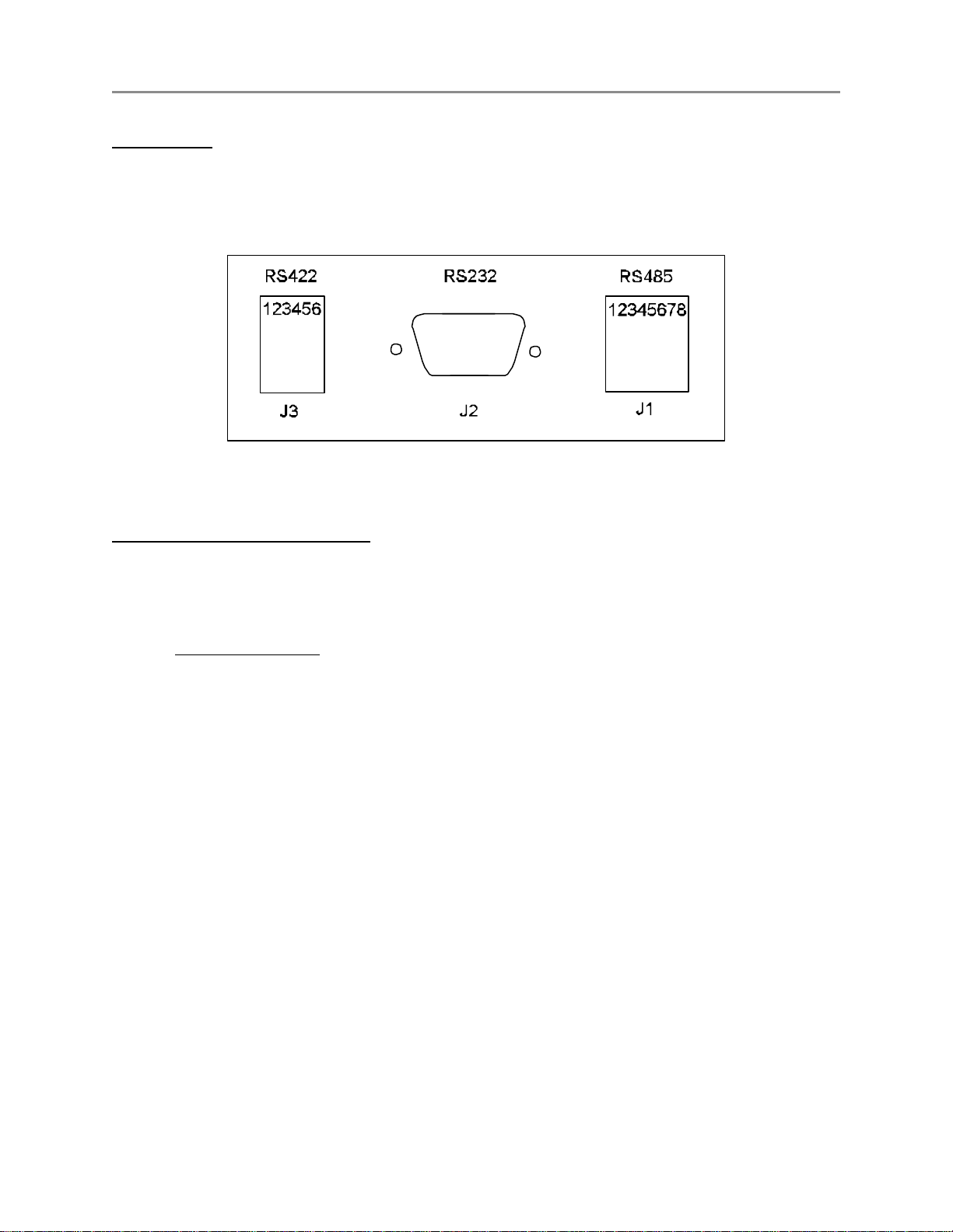
Figure C1 - Rear Panel Connectors
J1 - 8 pin (RJ45) Network connections :
Two modular jacks are provided at the rear of the DNA100. See Figure C1 . Use modular cables with straight
through pin configuration only! An 8-pin (RJ45) modular jack (KB171) and cord (BF640A) are required for
connection to the network.
PIN# - DESIGNATION
1 - No connection.
2 - +12 VDC power input
3 - Data + (positive)
4 - No connection.
5 - No connection.
6 - Data - (negative)
7 - -12 VDC power input
8 - External Alarm.
The maximum total network length is 7000 feet. A unshielded twisted pair cable should be used for the data
pair (24 or 22 AWG).
C6 RING COMMUNICATIONS INC.
Page 7

October 2004 DIGITAL NETWORK ADAPTER DNA100
Connect the DATA pair from the network to pins 3 and 6 of the RJ45 wall jack maintaining polarity of the pair.
If a remote power source is being used, the negative side of the supply must be referenced to Earth Ground,
as well as, the CB901 power supply.
J2 - 9 pin (DB9) RS232 signals :
The DNA100 has a RS232 serial port interface, J2, that can connect to a terminal or printer. Check your
terminal, printer or video switcher manual for the correct RS232 connector type, input, output and handshaking
signal connections.
The maximum length for a RS232 cable connecting the DNA100 and other equipment is 50 feet.
A null-modem (LapLink) cable can be used to connect a DNA100 and a laptop or computer together if they are
close enough to each other.
If you are going to make your own cable the following is a description of the pinout of the DB9 connector on the
DNA100.
J2 SIGNAL
PIN# NAME
1 DCD
2 RXD
3 TXD
4 DTR
5 GND Signal Ground.
6 DSR Not used.
7 RTS Request to Send, output.
8 CTS Clear to Send, input.
9 RI Not used.
DIRECTION/
DESIGNATION
Data Carrier Detect, input.
Receive Data, input.
Transmit Data, output.
Data Terminal Ready, output.
C7RING COMMUNICATIONS INC.
Page 8
October 2004 DIGITAL NETWORK ADAPTER DNA100
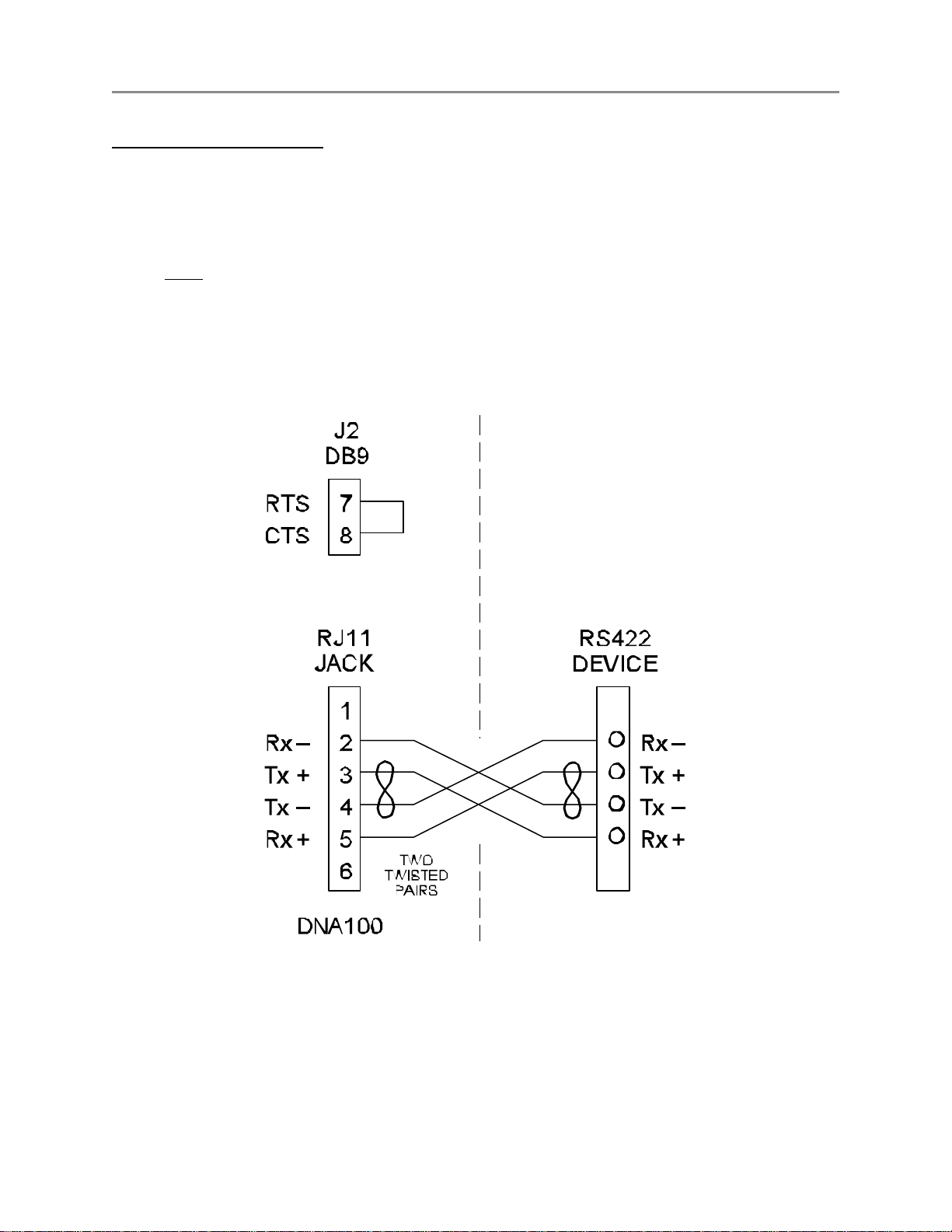
J3 - 6 pin (RJ11) RS422 signals :
A two twisted pair installation utilizing RS422 signals can be used to connect two bridges up to 7000 feet apart.
Use a six wire RJ11 cord with straight through wiring from J3 to another RJ11 jack on both sides of the
installation, and then use two twisted pairs between the two RJ11 jacks as shown in Figure C2.
A strap MUST be installed between RTS and CTS of J2 (DB9), in order to disable flow control for the RS422.
To do this, simply place a strap between pin 7 and pin 8 of J2. You could also solder this strap to a female
DB9 connector with solder lugs on the rear, then insert it into the J2 connector. Figure C2 illustrates the
strapping of J2.
Figure C2 - RS422 Interconnection
C8 RING COMMUNICATIONS INC.
Page 9

October 2004 DIGITAL NETWORK ADAPTER DNA100
Setting Baud Rate / Selecting Device Type (For switch locations see Figure C3.)
DIP switches SW3-1 through SW3-6 are used to set the desired baud rate for the RS232 device. SW3-7 and
SW3-8 are used to select the RS232 device the DNA100 is driving (see chart below).
BAUD
RATE
1 2 3 4 5 6 7 8
19200 1 0 0 0 0 1 Terminal 0 0
9600 1 0 0 0 1 0 0 = off Printer 0 1
4800 0 1 0 0 0 1 1 = on Not used 1 0
2400 0 1 0 0 1 0 Not used 1 1
1200 1 0 0 0 1 1
Note! The Video switcher software is moved to DNA200
The I/O Module software is moved to DNA300
SW3
DEVICE
SW3
Communication Protocols
Aside from the baud rate, the terminal emulation should be set for VT100.
The DNA100 has No Parity, 8 Data Bits, and 1 Stop Bit.
Hardware flow control is used (RTS/CTS). The DNA100 will send data only if CTS is high from the other device.
Compatible emulation software:
Procomm Plus
Terminal for Windows 3.11
Hyper Terminal for Windows 95/98
Set software flow control to OFF and hardware flow control to ON.
Set Pace character to >
C9RING COMMUNICATIONS INC.
Page 10

October 2004 DIGITAL NETWORK ADAPTER DNA100
Setting Network and Device Address
DIP switch SW2 is used to set the address of the DNA100. See SE TTING NETWORK ADDRESS of Chapter A -
NETWORK for a full description for setting addresses, as well as, an addressing chart.
NOTE
If any DIP switches are changed while the DNA100 is operating,
it must be RESET or powered off and then on, in order for the
changes to become valid.
External Alarm Output
If an external signaling device is required in addition to the audible signal in the terminal device, a driver is
available at the RJ45 jack. The driver can be directly connected to a small audible alarm signal such as the
Sonalert 24 volt series. To connect a Sonalert, attach the positive wire from the Sonalert to pin 2 (positive
supply) of the RJ45 jack and the negative wire from the Sonalert to pin 8 of the RJ45. Any time the terminal
audible signal is activated the external alarm output pin will be connected to the negative supply activating the
Sonalert.
If a load larger than 100 mA must be connected to the external alarm output such as a strobe light or
mechanical bell, use the external alarm output driver to activate a 24 volt relay then connect the heavier load
to the relay contact(s). A separate power pair must be used to power the external device to avoid a power drop
in the DNA100 due to the surge of power from the external device.
C10 RING COMMUNICATIONS INC.
Page 11

October 2004 DIGITAL NETWORK ADAPTER DNA100
FRONT PANEL SWITCHES AND INDICATORS - Figure C3
SWITCHES
SW1 - Reset. Creates a local reset for this node only.
SW2 - Node & Network Address
SW3 - RS232 Baud Rate, Device selection
L.E.D.'s (left side, network)
RUN - Indicates the local processor in the DNA100 is running. Will illuminate after power up or reset.
MASTER - Will light steady if this node is the master on the network. There can only be one master on each
network. On power up, each device waits for a response from a master. If no response is received,
then this device will take over as a master. Therefore, the first device powered up will be the
master.
TX - Transmit data to the Network. Will flash when the DNA100 sends data out on the Network. If the
Master LED is on, the TX LED will flash constantly. When the Master LED is off, TX will only flash
when transmitting to other devices.
RX -
L.E.D.'s (right side, RS232)
RTS CTS -
TX -
RX - Receive data. Input from RS232 device. Will flash when keys are pressed on the terminal device or data
Receive data from the Network. Will flash when data is transmitted from another device to the network.
If the Master LED is on, the RX LED will flash when other devices respond to scanning from the Master.
When the Master LED is off, the RX LED will flash constantly.
Request to send. Output, indicates the DNA100 is ready to receive data from the RS232 device.
Clear to send. Input, (selectable for internal or external input) illuminated when the RS232 device
is ready to receive data from the DNA100.
Transmit data. Output to RS232 device. Should flash every second when the time is updated or
data is transmitted to the RS232 device.
is sent to the DNA100.
Figure C3 - Front panel indicators
C11RING COMMUNICATIONS INC.
Page 12

October 2004 DIGITAL NETWORK ADAPTER DNA100
MENU SYSTEM OPERATION
2004/09/22 RING CRISIS ALERT SYSTEM 14:57:42
===================================================================
1- STATUS DISPLAY
2 - SET DATE/TIME
3 - CRT EMULATION
4 - NETWORK MONITOR
5 - NETWORK INFORMATION
6 - COMMUNICATIONS LINK
7 - CONFIGURE (DXC901/DXA100)
8 - BACKUP (DXC901/DXA100)
9 - RESTORE (DXC901/DXA100)
10 - MEMORY DISPLAY
11 - PACKET MONITOR
Figure C4 - Main Menu
MAIN MENU (?)
When a DNA100 is initialized, after power on or reset, the STATUS DISPLAY is brought up automatically (see
STATUS DISPLAY option below). To access the MAIN MENU the user must press and hold the Control (CTRL) key
and then press X on the terminal keyboard (CTRL-X).
The MAIN MENU displays the date and time on the top line and eight options. To choose an option from the MAIN
MENU, move the highlighted line by using the 8 or 9 (UP or DOWN) arrows on the keyboard, or enter the number
associated with the menu option required, highlighting your choice, and then press the enter key.
C12 RING COMMUNICATIONS INC.
Page 13

October 2004 DIGITAL NETWORK ADAPTER DNA100
MENU OPTIONS:
1 - STATUS DISPLAY (See Figure C5 & Figure C6): Default power up screen. This option allows the user
to view the real time status of all supervised stations and to receive and handle events. To go to the MAIN MENU
from STATUS DISPLAY press and hold CTRL then press X.
2 - SET DATE/TIME : Select to set network date and/or time. The date format is YY/MM/DD and time is in
24 hour format, HH:MM:SS. Use the 7 and 6 (LEFT and RIGHT) arrows to place the cursor on the digits you
wish to change, and press the 8 or 9 (UP or DOWN) arrows to increase or decrease the digits until the correct
date and/or time is set. Pressing ESC will return you to the M AIN MENU.
3 - CRT EMULATION : To set emulation mode. Wyse 350 for color terminal, Wyse 50 for monochrome terminal
or VT100 for PC emulation . Enter the number on the keyboard to select your choice. Press ESC to return to
main menu.
4 - NETWORK MONITOR (See Figure C13): Displays all active nodes on all active networks including receive
errors and retransmissions. Useful during installation and trouble shooting or basic network management. Press
ESC to return to the M AIN MENU.
5 - NETWORK INFORMATION (See Figure C14): Displays all active nodes on all active networks including
receive errors, retransmissions, software versions, and more for each node. Provides more useful information
regarding each node in the system to aid in troubleshooting during installation or general network maintenance.
Press ESC to return to the M AIN MENU.
6 - COMMUNICATION LINK: Allows communication with DXC910, DNA200, DNA300 and DNA400 (used for
configuration).
7 - CONFIGURATION (DXC901/DXA100) : Allows for configuratio of DXC901/DXA100.
8 - BACKUP (DXC901/DXA100) : Allows for backup of programmed data in the DXC901/DXA100.
9 - RESTORE (DXC901/DXA100) : Used for uploading data saved during BACKUP in DXC901/DXA100
10 - MEMORY DISPLAY : Used to view memory locations of any node on the system. Useful for technicians
to view error counters and for system software debugging. You will be prompted for Network Address and
starting Memory Address. Once entered the next 64 memory locations are displayed. If the DNA100 Network
Address presently being used by your terminal is inserted, the next 128 memory locations are displayed
instead. Press ESC to return to the M AIN MENU.
11 - PACKET MONITOR (See Figure C15): For use by technical support staff ONLY for monitoring all network
traffic, polling and responses for all node addresses for a specific network address. Press ESC to return to the
MAIN MENU.
C13RING COMMUNICATIONS INC.
Page 14

September 2000 STATUS DISPLAY DNA100
1- STATUS DISPLAY (See Figure C5 & Figure C6)
The upper half of the STATUS DISPLAY shows the status of up to 50 supervised subscriber positions
simultaneously. When a system has more than 50 supervised subscribers the 7 and 6 (LEFT and RIGHT)
arrows are used to scroll the screen left and right one column at a time. The bottom half of the screen, used
for event handling, does not move. The upper half of the display will view the 50 subscribers in five columns of
10 rows. The station dial numbers will be on the left-hand side of each column while it’s status (OK, CALL,
FAULT, BUSY, etc.) will be on the right-hand side. Figure C6 shows an example of a status display with
different statuses for 10 different stations in the left-most column. All stations will be displayed in ascending
numerical order starting from the left, working down the column, and then moving to the next column to the
right, etc. Unused areas of the upper display area will show ellipses ( .... ) in place of station numbers and
statuses.
If the DXC901, SUBSCRIBER ADDRESS $FF, is programmed as a SUBSCRIBER TYPE 1, with a text description and
a dial number code, the number will be displayed in the first column on the left. All reset activity from this stage
then can be printed to the defined printer. This is useful when a system is installed with many networks and/or
stages. Figure C5 & Figure C6 show what the DXC901 status would look like on the STATUS DISPLAY. It is
the “01 OK” on the top line of the leftmost column. Figure C12 shows what the NETWORK CONFIGURATION should
look like to get this result on the STATUS DISPLAY. (See NETWORK CONFIGURATION - SUBSCRIBER ADDRESS later
in this chapter for more details).
The lower half of the status display screen indicates status of five incoming annunciated events. If more than
five annunciated events are in queue (QUE), use the 8 and 9 (UP and DOWN) arrows to scroll to your choice.
There is room in the queue for up to 60 annunciated events.
STATUS DISPLAY
=========================================================================
01 OK .... ..... .... ..... .... ..... .... .....
0101 OK .... ..... .... ..... .... ..... .... .....
0102 OK .... ..... .... ..... .... ..... .... .....
0103 OK .... ..... .... ..... .... ..... .... .....
0104 OK .... ..... .... ..... .... ..... .... .....
0105 OK .... ..... .... ..... .... ..... .... .....
0106 OK .... ..... .... ..... .... ..... .... .....
0107 OK .... ..... .... ..... .... ..... .... .....
0108 OK .... ..... .... ..... .... ..... .... .....
0109 OK .... ..... .... ..... .... ..... .... .....
=========================================================================
QUE DATA TIME PRI STATUS EXT LOCATION DESCRIPTION
-------------------------------------------------------------------------
----------------------------------------------------------------------- 00 2004/08/28 14:27:38 IDLE 0111 MASTERSTATION 111
========================================================================
Figure C5 - Status Display, Idle
C14 RING COMMUNICATIONS INC.
Page 15

September 2000 STATUS DISPLAY DNA100
Description of Status :
OK - Supervised station in idle.
CALL - Incoming event in queue, designated as CALL by annunciating device.
ALARM - Incoming event in queue, designated as A LARM by annunciating device.
TALK - In conversation with this DNA100's master station.
FAULT - Incoming event indicating a hardware problem at/to that location.
PARK - An event placed on hold.
BUSY - Another Display is handling this call.
PWRFAIL - Power failure in a device (CB901 lost power and is running on batteries).
ACKNOWL - Non voice event has been acknowledged (such as PWRFAIL).
Description of Status Headings :
QUE
DATE/TIME PRI
STATUS
EXT
LOCATION DESCRIPTION -
The bottom line of the STATUS DISPLAY is the status for the master station for this DNA100's display.
QUE
DATE/TIME STATUS - Status of the Master station. (IDLE, TALK, WAIT, DIAL)
EXT - Dial number of the Master station
LOCATION DESCRIPTION - Text description of this Master station. Created during NETWORK
- Actual numbered position in the queue for incoming events.
The date and time the event was detected.
- Priority level of incoming event (1 - 9; 1 - highest, 9 - lowest).
- Status of each line (CALL, FAULT, TALK, PARK, BUSY, ALARM).
- The dial number of the calling station.
Text description of calling location. Created during NETWORK CONFIGURATION.
- The total number of events in queue
The present date and time (updated every second)
CONFIGURATION.
C15RING COMMUNICATIONS INC.
Page 16

September 2000 STATUS DISPLAY DNA100
Additional Status For Master Display Line :
IDLE - Indicates no DNA100 activity present at the master station.
DIAL - Indicates the DNA100 sent a request to dial. It sends a request to dial when an attempt is made
to answer an incoming event.
WAIT - Indicates status change for master. No keyboard entries will be accepted during WAIT state.
WAIT status occurs after the master cancels an event that was handled.
TALK - Master station is in conversation initiated by the DNA100. The DNA100 must be used to cancel
the conversation to remove the TALK status from the display line.
Operation :
IDLE -
When there are no annunciations (ALARMS, FAULTS or CALLS) to display, QUE will display 00, the TIME will
always be visible and the event display lines will be off. The real-time status display will show all stations
programmed to report to this annunciator as OK unless FAULTS are present in the system. In IDLE mode the
Intercom master station assigned to the CRT will also be idle and may be used in normal intercom mode by
using the dial pad on that station. Unused slots on the screen are filled with ellipses (...dots....).
INCOMING EVENT -
When the CRT DISPLAY receives an event a display line will appear and an audible tone will be heard from the
terminal. There is room to display five events in the queue. The middle line will be highlighted as the current line
that can be activated. See HANDLING MULTIPLE INCOMING ANNUNCIATIONS later in this chapter. The QUE will show
the number of display lines in use. The user should always note the status of the event (ALARM, CALL, FAULT,
PARK) before responding since the incoming status of the line will not be apparent when answered. The event
lines will be placed in queue in the order they are received if they all have equal priority. When an event with
greater priority is received it is placed ahead of existing events with lower priority level. Priority (PRI) level is
programmable from 1 through 9, 1 being top priority (see NETWORK CONFIGURATION for programming).
HANDLING AN EVENT - The SPACE BAR
Once the status has been observed, the current highlighted display line can be answered by pressing the
SPACE BAR on the CRT keyboard. When the SPACE BAR is pressed, the audible annunciation tone will stop, and
the DXC901 will connect the intercom master station at the CRT DISPLAY with the substation that initiated the
event. A warning tone will sound at both stations, and you may begin speaking after the tone. The intercom will
normally switch your voice hands free, although it may be necessary to use the 'T' button on the intercom
station for simplex operation (push to talk) to overcome background noise at either location. The 'T' may also
be used whenever you want to continue monitoring a station for information or security reasons.
C16 RING COMMUNICATIONS INC.
Page 17

September 2000 STATUS DISPLAY DNA100
PRIORITY OVERRIDE - Intercom Privilege Feature
The master station at the CRT DISPLAY should be programmed with the "Priority override" privilege by SVT.
If a busy or privacy signal is encountered, you may then press the 0 (zero) key on the intercom to override the
signal and obtain voice contact before the intercom times out (default is 15 seconds for time out). If the intercom
times out, you must dial the EXTENSION number shown on the DISPLAY line manually on the intercom ignoring
leading zeros, and then use the priority override privilege. All substations reporting to an annunciator may also
be programmed with "Privacy Category, Never" through SVT to avoid having to use the Priority feature on a
station that appears in privacy.
REMOTE CONTROL - The O key
This key is used for Door Lock Control of the connected Substation.
DXC901 sends DTMF digit 5 to Substation
DXC910 sends DTMF digit 5 to Substation
DXA100 sends out event REMCON
CANCEL A CONNECTION - The X key
When the intercom call is completed, press the X key on the CRT DISPLAY keyboard, this will cancel both the
intercom connection and the current DISPLAY line.
NOTE
Do not use the 'X' on the intercom station to cancel a call
placed by the DNA100. It will only drop the intercom call and not
the display line. This will prevent the substation from initiating
any events until the display line is cleared.
A FAULT will return within two seconds after being canceled if it is a solid fault. FAULTS can occur intermittently
during the scanning of the system due to electrical interference or disturbance at, or near, the station or its
cable. Each substation is scanned for faults 80 times per second. Hard faults can be removed from the system
temporarily by setting their device type to 0 in NETWORK CONFIGURATION and then reprogramming when the fault
is corrected.
PARK - The P key
PARK is used to temporarily hold events that you need to get back to after handling other events or obtaining
information. Solid FAULTS can also be placed in PARK to silence the audible tone until the problem is corrected
by a service person.
C17RING COMMUNICATIONS INC.
Page 18

September 2000 STATUS DISPLAY DNA100
HANDLING MULTIPLE INCOMING EVENTS -
If the QUE indicator displays a number greater than five, you can use the 8 or 9 (UP or DOWN) arrow keys to
view the additional events and decide which lines should be handled first based on location of event or PRIORITY
level. If the scrolling feature is not used, events can be handled on a first in first out basis by starting at the
current line. When each event is canceled each DISPLAY line will automatically move into the middle highlighted
line, and the middle DISPLAY line will be used each time until all lines are handled.
SILENCING THE AUDIBLE ANNUNCIATOR TONE -
When an incoming event is received and cannot be handled immediately, the tone can be temporarily silenced
by pressing the X key on the terminal keyboard. If any additional activity occurs, the audible annunciation tone
will sound again.
The audible tone will also sound if another event is received while you are presently handling one. Two options
are available to handle an event while in conversation: One is to complete the present event, press cancel, then
proceed to handle the additional events. The second option is to place the present event in PARK, then answer
the additional events to assess the priority of the event handling using Park or “X” (cancel) as needed.
STATUS DISPLAY
=========================================================================
01 OK .... ..... .... ..... .... ..... .... .....
0101 OK .... ..... .... ..... .... ..... .... .....
0102 FAULT .... ..... .... ..... .... ..... .... .....
0103 BUSY .... ..... .... ..... .... ..... .... .....
0104 OK .... ..... .... ..... .... ..... .... .....
0105 TALK .... ..... .... ..... .... ..... .... .....
0106 CALL .... ..... .... ..... .... ..... .... .....
0107 FAULT .... ..... .... ..... .... ..... .... .....
0108 CALL .... ..... .... ..... .... ..... .... .....
0109 ALARM .... ..... .... ..... .... ..... .... .....
=========================================================================
QUE DATA TIME PRI STATUS EXT LOCATION DESCRIPTION
------------------------------------------------------------------------ 01 2004/08/27 13:36:49 01 ALARM 0109 LEVEL C1 BUILDING 3
02 2004/08/27 13:34:22 04 CALL 0106 AREA Z - ZONE 7/OUTSIDE
03 2004/08/27 13:36:05 04 TALK 0105 ROOM 6 BUILDING 6
04 2004/08/27 13:42:19 05 FAULT 0102 ROOM 3 BUILDING 6
05 2004/08/27 13:43:23 05 BUSY 0103 DOOR 5A ZONE 2/INSIDE
----------------------------------------------------------------------- 07 2004/08/28 15:27:38 IDLE 0111 MASTERSTATION 111
========================================================================
Figure C6 - Status Display, Active
C18 RING COMMUNICATIONS INC.
Page 19

March 2004 NETWORK CONFIGURATION DNA100
NIGHT TRANSFER MODE -
The DNA100 is placed in Night Transfer mode by placing the associated intercom station in privacy. Calls to
this DNA100 will now be sent to the next Annunciator device in the Annunciator address chain (for the sub
station) without the programmed delay. The delay is used in normal Day mode to delay calls before they
transfer (Max delay 9.9 minutes). When the DNA100 is in transfer mode the time display will flash the word
“TRANSFER” . Calls are still qued in the DNA100 but the beeper is silenced. The beeper will beep once every
60 seconds as a reminder that the we are in transfer mode. The DNA100 may answer calls in the Que while
in transfer mode.
C19RING COMMUNICATIONS INC.
Page 20

March 2004 NETWORK CONFIGURATION DNA100
NETWORK MONITOR See Figure C13
The NETWORK MONITOR is activated by selecting option five on the MAIN MENU screen. The NETWORK MONITOR
allows real time viewing of all networks and nodes presently operating in a Crisis System. This screen should
be used by technical personnel to verify network operation during installation and trouble shooting. The NODES
shown are as seen by the master of that network. FREE, RETR, and RXERR are master information as well. To
return to the M AIN MENU at any time press ESC.
When a node number is displayed steady (not flashing on and off) and the error columns are zero and/or not
incrementing then those nodes are 'on-line' and working. Node numbers that are flashing may also increase the
RETR and RXERR counters and indicate a trouble on that network. This could be due to an internal failure in
a node or a poor data connection in the network.
If the network has excessive traffic, the FREE pool of elements will become depleted. This could lead to loss
of communicati on with this node or network. Excessive traffic can be caused by one defective node, poor quality
or damaged data pairs.
2004/01/16 NETWORK MONITOR 15:47:25
==========================================================================
NET NODES FREE RETR RXERR NET NODES FREE RETR RXERR
00 ________ 00 00 00 16 ________ 00 00 00
01 76_4_2_0 27 00 00 17 ________ 00 00 00
02 _____2_0 27 00 00 18 ________ 00 00 00
03 ________ 00 00 00 19 ________ 00 00 00
04 ________ 00 00 00 20 ________ 00 00 00
05 ________ 00 00 00 21 ________ 00 00 00
06 ________ 00 00 00 22 ________ 00 00 00
07 ________ 00 00 00 23 ________ 00 00 00
08 ________ 00 00 00 24 ________ 00 00 00
09 ________ 00 00 00 25 ________ 00 00 00
10 ________ 00 00 00 26 ________ 00 00 00
11 ________ 00 00 00 27 ________ 00 00 00
12 ________ 00 00 00 28 ________ 00 00 00
13 ________ 00 00 00 29 ________ 00 00 00
14 ________ 00 00 00 30 ________ 00 00 00
15 ________ 00 00 00 31 ________ 00 00 00
Figure C7 - Network Monitor
C20 RING COMMUNICATIONS INC.
Page 21

March 2004 NETWORK CONFIGURATION DNA100
NET - Network number. Networks 01-30 are for standard nodes, 00 is not used, and 31 is reserved for
a DIGITAL EXCHANGE MASTER bridge.
NODES - Node number. The master of that network is receiving messages from the nodes displayed. Node
numbers are from 0-7 listed from right to left.
FREE - The number of free queue elements for transmission. In each node, there is a free pool of
message locations that can contain queued up messages generated for the node’s internal
housekeeping. When queued messages are handled, the queue element is placed back into the
pool. This number is the remaining queue elements that can be used by the master node. This
number is usually HEX 28 but will decrease depending on data traffic.
RETR
RXERR
- The number of retransmissions logged by the master of this network. To reset the counter the
master must be reset. Some retransmissions may exist on a good network due to data
disturbance when installing or removing a node, or if transmissions are sent to a node that is not
present on the system.
- Number of receive errors logged by the master of this network. To reset the counter the master
must be reset.
C21RING COMMUNICATIONS INC.
Page 22

October 2004 NETWORK INFORMATION DNA100
NETWORK INFORMATION See Figure C14
NETWORK INFORMATION is activated by selecting option five on the MAIN MENU screen. Then enter a network
number or * to view all networks. This screen can be used if there is a question about how the network is
operating or if you want to see details about individual nodes on the system. While NETWORK MONITOR shows
information based on the master’s point of view, NETWORK INFORMATION shows information from the individual
node’s point of view. The information here is based on each node as opposed to the entire network. It’s very
useful for finding that errant node or for general information about each node in the system. Each line represents
one node in the system and displays information described on the next page.
Unlike NETWORK MONITOR, NETWORK INFORMATION is not a real time display. The information displayed is not
updated while in NETWORK INFORMATION, to update the information you must exit and then re-enter.
To exit and return to the M AIN MENU at any time, press ESC.
2004/11/02 Network information 15:47:25
========================================================
Network number (0-31,*):*
ADDR NET NODE TYPE VERSION FREE RETR RXERR HOURS
---- --- ---- --------- ---------- ---- ---- ----- ---- 08 01 0 DXC901 2004/01/30 25 00 00 0007
0A 01 2 DNA100 2004/10/26 25 00 00 0007
0C 01 4 DAD104 2003/03/11 25 00 00 0007
0E 01 6 DNA100 2004/10/26 25 00 00 0000
0F 01 7 DNA100 2004/10/26 25 00 00 0007
10 02 0 ******
12 02 2 DAD104 2003/03/11 25 00 00 009A
Figure C8 - Network Information
C22 RING COMMUNICATIONS INC.
Page 23

October 2004 NETWORK INFORMATION DNA100
ADDR - Network address. The network address of the node on that display line.
NET - Network number. The network the device on the display line is a member of.
NODE - Node number. The node number of the device on the display line.
NOTE
REMEMBER -- Address, Net, and Node are related to each other.
The Address is a combination of Net and Node. (See SETTING
NETWORK ADDRESS of Chapter A - NETWORK for full explanation.)
TYPE
VERSION
FREE - The number of free queue elements for transmission. In each node, there is a free pool of
RETR - The actual number of retransmitted messages logged from the device on this display line.
RXERR
HOURS
- Type of device. The device type (DXC901, DNA100, DAD104, etc.) of the node on that
display line.
- Version date. The version date of the device on this display line. The date is in the format
of YYYY/MM/DD (year, month, day). To be compatible with the NETWORK INFORMATION
screen the version date of the firmware has to be dated 960105 or later. If the firmware in
the device is older, it will display asterisks (***) in place of TYPE and nothing else to the
right of TYPE for that display line.
message locations that can contain queued up messages generated for the node’s internal
housekeeping. When queued messages are handled, the queue element is placed back
into the pool. This number is the remaining queue elements that can be used by the device
on this display line. This number is usually HEX 28 but will decreas e depending on data
traffic.
To reset the counter this device mu st be reset. Some retransmissions may exist on a good
network due to data disturbance when installing or removing a node, or if transmissions are
sent to a node that is not present on the system.
- Number of receive errors logged by the device on this display line. To reset the counter the
device on this display line must be reset.
- Time since reset. Number of hours in hexadecimal format.
C23RING COMMUNICATIONS INC.
Page 24

March 2004 PACKET MONITOR DNA100
PACKET MONITOR
Option eight on the main menu is PACKET MONITOR. This feature allows a technical person to actually view the
data packets on the network. This monitor is a powerful debugging tool used primarily for software development
and testing although it also can be utilized for trouble shooting.
To exit and return to the MAIN MENU, press Esc. This will reset the DNA100.
An example of the packet monitor is shown in Figure C15.
A B C D E F G
00 FF<0C UPDREQ 09 FF<01 0223 H I J
00 0E<08 RESET 30 01<00 0010 00 45 40 19 08 01 03 20 20 33 34 35 36 37 38 39
30
31 32 33 34 35 36 37 38 39 30 31 32 33 34 35 36 37 38 39 32 07A8
00 0C<08 TALK 30 01<07 0017 01 09 37 19 08 01 93 20 42 45 44 20 41 20 20 20
20
46 4C 4F 4F 52 20 35 20 20 20 20 20 20 20 20 20 20 20 20 20 20 20 06A0
00 0E<08 CALL 30 01<06 0016 01 52 40 19 08 01 93 20 44 4F 4F 52 20 35 20 54
48
49 52 44 20 46 4C 4E 4F 52 20 20 20 20 20 20 20 20 20 20 20 074F
00 0A<08 CALL 30 01<06 0016 01 52 40 19 08 01 93 20 44 4F 4F 52 20 35 20 54
48
49 52 44 20 46 4C 4E 4F 52 20 20 20 20 20 20 20 20 20 20 20 07F0
Figure C9 - PACKET MONITOR EXAMPLE
Each lettered item in the example indicated by an arrow is described on the following page. These descriptions
are intended to assist field personnel to explain PACKET MONITOR listings to a Ring Communications technician.
They are not intended for a complete understanding of the data packets on the network.
NOTE
Do not enter packet monitor from the main system's operational
display. Use your spare DNA100/display using an individual
node address.
C24 RING COMMUNICATIONS INC.
Page 25

March 2004 PACKET MONITOR DNA100
A = Error counter. Maintains total number of errors on network. This number is stored in the network master
and can be reset by resetting the network master. A secure network will have no errors but some are
possible if nodes are installed or disconnected and cause data disturbance.
Possible errors are:
- checksum error
- network error
- receiver overrun error
- noise error
- framing error
- number of retransmits
To node. In this example FF indicates a broadcast to all nodes. Other numbers indicate a node address.
B =
From node. The example shows node 0C sending to FF (broadcast).
C =
Event definition CALL, CONNECT, CLEAR, PARK, TALK, BUSY, etc.
D =
Total number of bytes in this packet, 09.
E =
Device to/from. The node may represent a device such as a master station. The example shows device
F =
01 (line equipment 01 is the second subscriber port in the CB901) sending to FF (broadcast)
Checksum. The total of all data in the packet. This is recalculated when received and checked for
G =
accuracy. If the calculated checks um does not match the received checksum then a request to retransmit
the packet occurs.
H = Time. Time is transmitted by the network master as a broadcast and the time may also be part of a
packet indicating when an event occurred. The format is SS:MM:HH (45:40:19).
I = Date. Date is transmitted by the network master as a broadcast and the date may also be part of a packet
indicating when an event occurred. The format is DD:MM:YY (08:01:03).
J = ASCII text field. The 30 character description for this device.
C25RING COMMUNICATIONS INC.
Page 26

October 2004 ACTIVITY LOG PRINTER DNA100
ACTIVITY LOG PRINTER
A serial RS232C printer can be attached to a DNA100 to provide a complete activity log of system. All stations
to be logged must have the printer defined in their SAR. The DNA100 must be configured to drive a printer by
setting SW3-7 off and SW3-8 on. The printer must have a RS232C serial interface. The standard print format
is 80 columns, 66 lines per page.
Figure C16 shows a sample printed page of the Crisis Alert Activity Log Printer.
Description of Status Headings :
DATE
TIME The actual time the event on each line occurred.
PRI PRIORITY of the incoming event.
STATUS Status of each event (CALL, FAULT, CONNECT, PARK, CANCEL, RESET , ALARM).
EXT The dial number of the station generating the event.
LOCATION DESCRIPTION Written description of the location or device stated under the EXT heading.
CONNECTED TO Indicates the station connected to the device generating the event.
Description of Status :
CALL
CONNECT
FAULT
Indicates a hardware problem for the location printed and sent to the annunciator five seconds after the
fault occurs. The time delay is due to a noise filter in the DXC901 that only records solid faults.
The DATE this page was printed. If the date changes before the page is full a new page is
printed with events for the new date.
CALL to annunciator. This only indicates a call condition was placed from type 1 sub station
or type 3 sub-master station.
Indicates an event being handled in accordance with the annunciator display through Crisis
Alert. (See HANDLING AN EVENT earlier in this Chapter or in Chapter D - DAD104)
PARK An event that was placed in PARK. A new CONNECT message will be generated when this event
is retrieved again.
CANCEL Indicates a disconnection of two devices that were previously connected. For example, a
master station that presses the ‘X’ key on the terminal keyboard using a DNA100 will
generate a CANCEL event.
ALARM ALARM to annunciator. This indicates that an alarm condition was placed from a type 3 sub-
master station.
PWRFAIL The CB901 has detected loss of Power. It is now running on battery backup.
ACKNOWL An event has been acknowledged by a DAD104 (such as PWRFAIL).
CLEAR
C26 RING COMMUNICATIONS INC.
The Power has been restored to normal for the CB901 central exchange.
Page 27

October 2004 ACTIVITY LOG PRINTER DNA100
Additional Status For Devices :
RESET Indicates when a device has been RESET. This message is only printed if the device has a Printer
Address defined during NETWORK CONFIGURATION. To enter a description for the DXC901 Digital
Exchange Controller use Subscriber address $FF and enter it as a SUBSCRIBER TYPE 0 station with the
description needed. The dial number if inserted can be displayed on a CRT status display. Generally
a two digit number is used to indicate a building or stage number in a multi stage configuration. Do not
enter a priority or program channel for the DXC901.
C27RING COMMUNICATIONS INC.
Page 28

October 2004 ACTIVITY LOG PRINTER DNA100
ACTIVITY LOG
FOR
RING CRISIS ALERT SYSTEM
-------------------------------------------------------------------- DATE TIME PRI TO EVENT FROM LOCATION
---------- -------- --- ---- -------- ---------------------------- 2004/08/24 15:59:50 RESET Activity LOG Printer
2004/08/24 16:28:12 2 10 CALL 17 Elevator 4A
2004/08/24 16:28:23 17 CONNECT 10 Security
2004/08/24 16:28:48 17 CANCEL 10 Security
2004/08/24 17:32:45 5 10 CALL 28 Gate E
2004/08/24 17:33:16 28 CONNECT 10 Security
2004/08/24 17:35:03 28 PARK 10 Security
2004/08/24 17:35:05 1 11 CALL 10 Security
2004/08/24 17:35:08 10 CONNECT 11 Lobby
2004/08/24 17:35:22 10 CANCEL 11 Lobby
2004/08/24 17:35:28 28 CONNECT 11 Lobby
2004/08/24 17:36:56 28 CANCEL 11 Lobby
Figure C10 - Activity Log Print Example
RING COMMUNICATIONS INC.
 Loading...