

Page 1
AlphaGen DCX2000 36VDC Portable Generator
Operation Manual
Effective: July 2013
Page 2

Safety Notes
Review the drawings and illustrations contained in this manual before proceeding. If there are any questions regarding
the safe installation or operation of the system, contact Alpha Technologies or the nearest Alpha representative. Save this
document for future reference.
To reduce the risk of injury or death and to ensure the continued safe operation of this product, the following symbols have
been placed throughout this manual. Where these symbols appear, use extra care and attention.
WARNING! ELECTRICAL HAZARD
ELECTRICAL HAZARD WARNING provides electrical safety information to PREVENT
INJURY OR DEATH to the technician or user.
WARNING! FUMES HAZARD
FUMES HAZARD WARNING provides fumes safety information to PREVENT INJURY OR
DEATH to the technician or user.
WARNING! FIRE HAZARD
FIRE HAZARD WARNING provides ammability safety information to PREVENT INJURY OR
DEATH to the technician or user.
There may be multiple warnings associated with the call out. Example:
WARNING! ELECTRICAL & FIRE HAZARD
This WARNING provides safety information for both Electrical AND Fire Hazards
CAUTION!
CAUTION provides safety information intended to PREVENT DAMAGE to material or equipment.
NOTE:
NOTE provides additional information to help complete a specic task or procedure.
ATTENTION:
ATTENTION provides specic regulatory/code requirements that may affect the placement of equipment and /or
installation procedures.
The following sections contain important safety information that must be followed during the installation and maintenance
of the equipment and batteries. Read all of the instructions before installing or operating the equipment, and save this
manual for future reference.
Page 3

AlphaGen DCX2000
36VDC Portable Generator
Operation Manual
041-135-B0-001, Rev. A
Effective Date: July 2013
Copyright 2013
Alpha Technologies, Inc.
member of The Group
NOTE:
Alpha denies responsibility for any damage or injury involving its enclosures, power supplies, generators,
batteries or other hardware, manufactured by Alpha or members of the Alpha Group, when used for an
unintended purpose, installed or operated in an unapproved manner, or improperly maintained.
NOTE:
Photographs and drawings in this manual are for illustrative purposes only and might not exactly match your
installation.
NOTE:
Review this manual before proceeding. If there are questions regarding the safe installation or operation of
this product, please contact Alpha Technologies or your nearest Alpha representative.
TM
Contacting Alpha Technologies: www.alpha.com
or
For general product information and customer service (7 AM to 5 PM, Pacic Time), call
1-800-863-3930
For complete technical support, call
1-800-863-3364
7 AM to 5 PM, Pacic Time or 24/7 emergency support
To report errors in this document, send email to:Techpubs@alpha.com
3041-135-B0-001 Rev. A (07/2013)
Page 4

Table of Contents
DCX2000 Portable Generator Safety Notes ......................................................................................................... 6
1.0 Introduction ............................................................................................................................................... 7
1.1 DCX2000 Generator Components ............................................................................................... 7
2.0 Operation .................................................................................................................................................. 9
2.1 Oil Level ........................................................................................................................................ 9
2.2 Fuel Level ................................................................................................................................... 10
2.3 Air Cleaner .................................................................................................................................. 11
2.4 Power System Connections ........................................................................................................ 12
2.4.1 Y-Style Connection ........................................................................................................... 12
2.4.2 Ring Lug Style Connection .............................................................................................. 13
2.4.3 Alligator Clamp Style Connection ..................................................................................... 14
2.5 Start-Up ....................................................................................................................................... 15
2.6 Operation at High Altitude ........................................................................................................... 16
2.7 Operation at Extreme Temperatures ........................................................................................... 16
2.8 Engine Shutdown ........................................................................................................................ 16
2.9 Output, Alarm and Oil LEDs ........................................................................................................ 17
3.0 Servicing ................................................................................................................................................. 18
3.1 Emission Control System ............................................................................................................ 18
3.2 Maintenance Schedule ............................................................................................................... 20
3.3 Changing Oil ............................................................................................................................... 21
3.4 Air Cleaner Service ..................................................................................................................... 22
3.5 Spark Plug Maintenance ............................................................................................................. 23
3.6 Spark Arrestor Maintenance ....................................................................................................... 24
4.0 Transport and Storage Instructions ........................................................................................................ 25
4.1 Transporting the Generator ......................................................................................................... 25
4.2 Exercising the Generator ............................................................................................................ 25
4.3 Short Term Storage ..................................................................................................................... 25
4.4 Long Term Storage ..................................................................................................................... 26
5.0 Troubleshooting ...................................................................................................................................... 27
6.0 Specications .......................................................................................................................................... 28
7.0 Warranty Information .............................................................................................................................. 29
7.1 California Emissions Control Warranty Statement ...................................................................... 29
7.2 Emission Control System Warranty ............................................................................................ 30
4 041-135-B0-001 Rev. A (07/2013)
Page 5

Figures & Tables
Fig. 1-1, DCX2000 Generator Components ......................................................................................................... 7
Fig. 1-2, Engine Serial Number ............................................................................................................................ 8
Fig. 2-1, Oil Level ................................................................................................................................................. 9
Fig. 2-2, Checking Fuel Level ............................................................................................................................. 10
Fig. 2-3, Checking Air Cleaner............................................................................................................................ 11
Fig. 2-4, Y-Style Connection ............................................................................................................................... 12
Fig. 2-5, Ring Lug Style Connection ................................................................................................................... 13
Fig. 2-6, Alligator Clamp Style Connection ......................................................................................................... 14
Fig. 2-7, Start-Up ................................................................................................................................................ 15
Fig. 2-8, Recommended Oil By Temperature ..................................................................................................... 16
Fig. 2-9, Fuel Valve ON/OFF Positions .............................................................................................................. 16
Fig. 2-10, Control Panel...................................................................................................................................... 17
Fig. 3-1, Air Quality Index Label .........................................................................................................................19
Fig. 3-2, Changing Oil......................................................................................................................................... 21
Fig. 3-3, Air Cleaner Assembly ........................................................................................................................... 22
Fig. 3-4, Spark Plug Maintenance ...................................................................................................................... 23
Fig. 3-5, Accessing the Spark Arrestor ............................................................................................................... 24
Fig. 4-1, Starter Grip ........................................................................................................................................... 26
Fig. 5-1, Replace Spark Plug.............................................................................................................................. 27
Table 2-1, LED States......................................................................................................................................... 17
Table 3-1, Maintenance Schedule ...................................................................................................................... 20
5041-135-B0-001 Rev. A (07/2013)
Page 6
DCX2000 Portable Generator Safety Notes
The manufacturer cannot anticipate every circumstance that may involve a hazard, therefore, these warnings are not
comprehensive.
WARNING! FUMES HAZARD
Engine exhaust contains carbon monoxide gas, which can be deadly in closed or poorly
ventilated areas.
WARNING! ELECTRICAL HAZARD
• Generator must be properly grounded.
• Do not make or break any connections while generator is running.
• Do not place or operate the generator in standing water, or expose it to a forced spray of
water.
• Ensure cables do not cross hot surfaces or sharp edges. Inspect cables before and after
each use.
WARNING! FIRE HAZARD
• Never operate the generator near combustible materials.
• Never refuel the generator in the vicinity of open ames of heat sources. Do not smoke near
the generator.
• Do not refuel the generator while engine is running. Allow generator to cool before refueling.
• Fuel spillage cleanup is the responsibility of the operator and should comply with local codes
and regulations.
• For re safety, the generator must be properly connected, maintained, and in compliance
with applicable codes and regulations.
• Drain oil and empty the fuel tank before transporting. Fuel can leak from the ller cap if the
generator is tilted.
CAUTION!
• Prior to each use, inspect the generator for leaks and damage. Immediately repair or replace any
damaged parts.
• The generator must be operated on level ground, not to exceed 15° slant.
• Use only vendor-authorized repair parts.
6 041-135-B0-001 Rev. A (07/2013)
Page 7
1.0 Introduction
The Alphagen DCX2000 portable DC generator supplies DC voltage to a power supply battery bus when
commercial AC power is not available. The generator is designed to be temporarily connected to the DC bus
of a standard Alpha 36V uninterruptable power supply (UPS). Upon loss of commercial AC power, the existing
batteries immediately supply the power supply inverters. After some interval of battery discharge, an operator
deploys the portable generator at the site to supply power to the DC bus.
1.1 DCX2000 Generator Components
Gas Cap
Spark Plug Access Cover
Starter Grip
LCD Display
Spark Arrestor
Exhaust Grill
Control Panel
Choke Lever
Fuel Primer
Fuel
Valve
Maintenance
Panel
Ground Stud
V: 40.3V I: 00.0A
P:0000W
Oil: OK ALM:
Time: 004H 27M
Fig. 1-1, DCX2000 Generator Components
ON
OFF
OUTPUT BREAKER
DC OUTPUT
ALARM
OUTPUT
OIL
ON
OFF
ENGINE
7041-135-B0-001 Rev. A (07/2013)
Page 8
1.0 Introduction, continued
1.1 DCX2000 Generator Components, continued
The engine serial number is stamped on the engine block (remove maintenance panel).
11085603
Serial Number
Fig. 1-2, Engine Serial Number
8 041-135-B0-001 Rev. A (07/2013)
Page 9
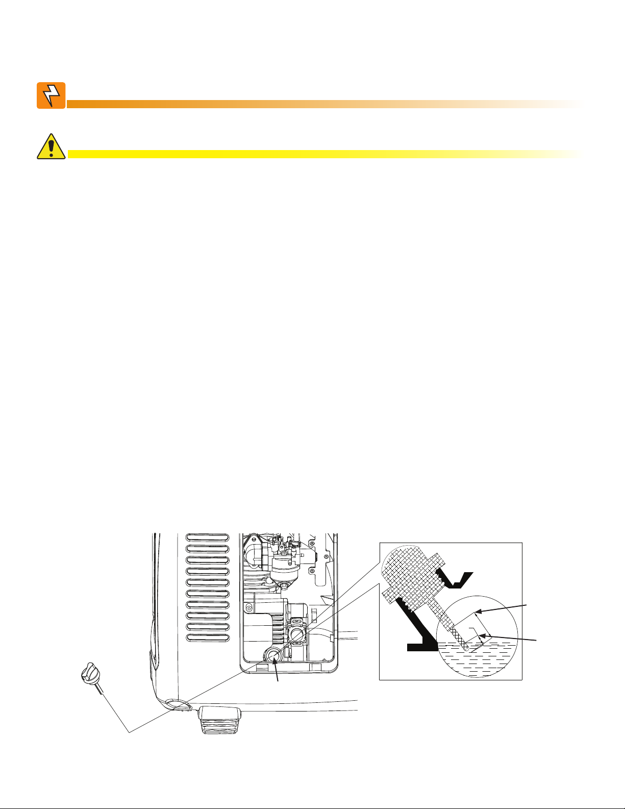
2.0 Operation
2.1 Oil Level
WARNING! ELECTRICAL HAZARD
Power OFF the generator engine and place on a level surface before servicing.
CAUTION!
• Using non-detergent oil or 2-stroke engine oil will shorten service life and void the warranty. Use only
high-detergent, premium quality, 4-stroke engine oil, certied to meet U.S. automobile manufacturer’s
requirements for API Service Classication SG/SF/SJ/SL/SM/SN. Use synthetic SAE 10W-40
viscosity oil unless operating at ambient temperatures below 32°F (0°C). For temperatures below
32°F, use synthetic SAE 0W-40 viscosity oil.
• Change the oil in a new engine within 4-6 hours of operation to clean any contamination or
manufacturing debris.
• Running the engine with low oil can cause serious damage.
• The Low Oil Alarm System will automatically stop the engine before the oil level falls below a safe
limit. To avoid an unexpected shutdown, inspect the oil level regularly.
Dipstick
Tools Required:
#2 Philips Head Screwdriver
Oil Drain Pipe
Procedure:
1. Remove the maintenance cover.
2. Using the slots in the oil drain pipe, remove the dipstick, wipe with a clean rag and reinsert, screw
down until tight.
3. Remove the dipstick to check the oil level.
4. If the oil level is below the lower level of the dipstick, rell to the top of the upper level marking. Do not
overll.
5. Reinsert the dipstick and screw down until tight.
Maximum
Oil Level
Minimum
Oil Level
L/2
L
Oil Fill Hole
Fig. 2-1, Checking Oil Level
9041-135-B0-001 Rev. A (07/2013)
Page 10
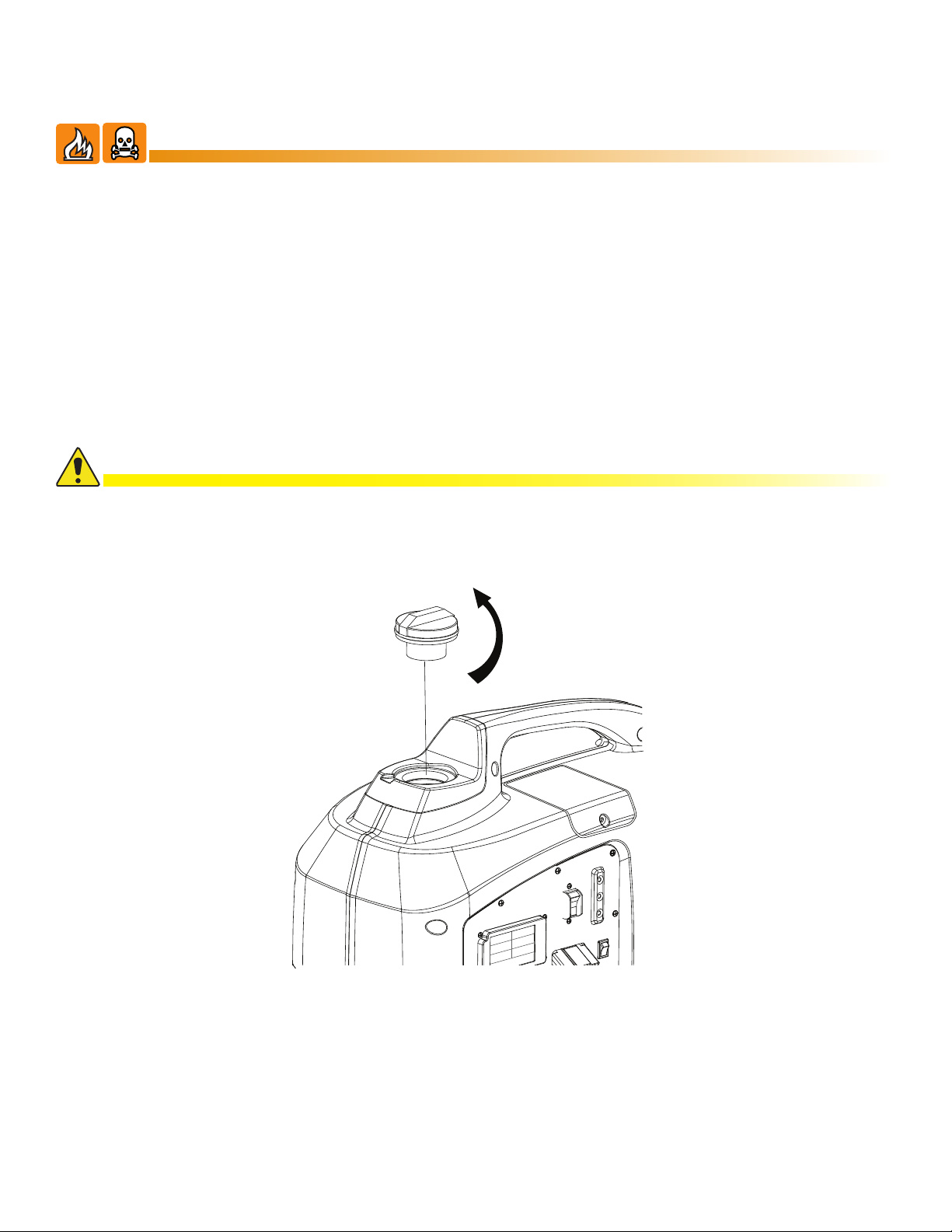
2.0 Operation, continued
2.2 Fuel Level
WARNING! FIRE & FUMES HAZARD
Gasoline is extremely ammable and can be explosive. Refuel in a well-ventilated area
with the engine OFF. Keep all smoking materials, sparks, and other sources of combustion
away from the generator during refueling.
The area must be free of spilled fuel before starting the engine. Avoid repeated or
prolonged contact with skin or exposure to vapor. KEEP OUT OF REACH OF CHILDREN.
Only use regular unleaded gasoline with the DCX2000 Generator. The fuel tank has a capacity of 1.7
gallons (6.5 Liters).
Procedure:
1. If the fuel level is low, rell to the top of the fuel strainer.
2. After refueling, tighten the fuel cap securely.
CAUTION!
Do not use an alternate fuel blend that contains more than 10% ethanol. Do not use gasoline
containing methanol. An octane rating of 87 or higher is recommended. Fuel system damage or engine
performance problems resulting from the use of fuels that contain an improper alcohol blend are not
covered under warranty.
Fuel Cap
Fig. 2-2, Checking Fuel Level
10 041-135-B0-001 Rev. A (07/2013)
Page 11

2.0 Operation, continued
2.3 Air Cleaner
CAUTION!
Never run the engine without the air cleaner element in place. Rapid engine wear will result from
contaminants entering through the carburetor into the engine.
Tools Required:
#2 Philips Head Screwdriver
Procedure:
1. Remove the maintenance cover.
2. Remove the three screws from the air cleaner. Remove the cover to check the element. Clean or
replace as necessary (see Section 3.4, Air Cleaner Service for details).
3. Replace the air cleaner element and cover. Tighten the screw.
4. Replace the maintenance cover and tighten the screw.
Air Cleaner
Case
Air Cleaner
Element
Air Cleaner
Cover
Fig. 2-3, Checking Air Cleaner
Captive Screw
Maintenance
Cover
11041-135-B0-001 Rev. A (07/2013)
Page 12

ALM/
RDY
RST
TPR
Rx/Tx PWR
E
T
H
REG
DS
ACT
LNK
BLUE = WARN
RED = OUT
GRN = OK
OUTPUT
ALARM
TEST
LRI
2.0 Operation, continued
2.4 Power System Connections
2.4.1 Y-Style Connection
i
STRG A
STRG B
FLASH = MIN ALM
STRG C
SOLID = MAJ ALM
STRG D
ON
BATTERY
BREAKER
I
O
OFF
~
OUTPUT 1
N
~
OUTPUT 2
N
ENV
BATTERY
TEMP
C
O
M
BATTERY
A
INPUT
/
B
C
/
D
Y-Style
Battery Pack
Adapter Cable
P/N 874-946-22
Generator Output Cable
50' P/N 876-011-21
30' P/N 876-011-20
3
2
F u s e
1
Fig. 2-4, Y-Style Connection
12 041-135-B0-001 Rev. A (07/2013)
Page 13

2.0 Operation, continued
ALM/
RDY
RST
TPR
Rx/Tx PWR
E
T
H
REG
DS
ACT
LNK
BLUE = WARN
RED = OUT
GRN = OK
OUTPUT
ALARM
TEST
LRI
2.4 Power System Connections, continued
2.4.2 Ring Lug Style Connection
i
STRG A
STRG B
FLASH = MIN ALM
STRG C
SOLID = MAJ ALM
STRG D
ON
~
OUTPUT 1
N
~
OUTPUT 2
N
I
O
OFF
BATTERY
BREAKER
ENV
BATTERY
TEMP
C
O
M
BATTERY
A
INPUT
/
B
C
/
D
Generator Output Cable
50' P/N 876-011-21
30' P/N 876-011-20
Ring Lug Style
Battery Pack Adapter Cable
P/N 874-946-21
Fig. 2-5, Ring Lug Style Connection
3
2
F u s e
1
Cable lugs connect directly
to the battery terminals
13041-135-B0-001 Rev. A (07/2013)
Page 14

2.0 Operation, continued
ALM/
RDY
RST
TPR
Rx/Tx PWR
E
T
H
REG
DS
ACT
LNK
BLUE = WARN
RED = OUT
GRN = OK
OUTPUT
ALARM
TEST
LRI
2.4 Power System Connections, continued
2.4.3 Alligator Clamp Style Connection
i
STRG A
STRG B
FLASH = MIN ALM
STRG C
SOLID = MAJ ALM
STRG D
ON
~
OUTPUT 1
N
~
OUTPUT 2
N
I
O
OFF
BATTERY
BREAKER
ENV
BATTERY
TEMP
C
O
M
BATTERY
A
INPUT
/
B
C
/
D
Generator Output Cable
50' P/N 876-011-21
30' P/N 876-011-20
Alligator Clamp Style
Battery Pack Adapter Cable
P/N 874-946-20
Fig. 2-6, Alligator Clamp Style Connection
3
RED
2
F u s e
1
BLACK
Ensure clamps lay at against
batteries, facing inward
14 041-135-B0-001 Rev. A (07/2013)
Page 15

2.0 Operation, continued
2.5 Start-Up
Before starting the engine, verify the output circuit breaker is in the OFF position.
Procedure:
1. Connect output cable to the generator’s DC output connection and the power supply.
2. Turn the fuel valve to the ON position. If the fuel tank was just lled, pump the fuel primer bulb 7 times
to get fuel to the carburetor.
3. Turn the engine switch ON.
4. Move the choke lever to the START position.
5. Pull the starter grip lightly until resistance is felt, then pull briskly out.
6. Move the choke lever to the RUN position after the engine warms up.
7. Turn the output circuit breaker ON.
8. Verify an output voltage of 39.5V on the display.
CAUTION!
Slowly return starter grip to position; do not allow it to snap back. Do not allow the rope to rub against
generator body while retracting.
START RUN
Choke Lever
Fuel Primer
Fig. 2-7, Start-Up
CAUTION!
Substantial overloading that continuously lights the overload LED (red) may damage the generator.
Marginal overloading that temporarily lights the overload LED (red) may shorten the service life of the
generator.
15041-135-B0-001 Rev. A (07/2013)
Page 16

2.0 Operation, continued
2.6 Operation at High Altitude
The standard carburetor air-fuel mixture will be excessively rich at high altitudes. This will decrease
performance and increase fuel consumption.
High altitude performance can be improved by installing a smaller diameter main fuel jet in the carburetor.
If you always operate the generator at altitudes higher than 5000 feet (1500 m) above sea level, have an
authorized Alpha Service Center install a high altitude main jet.
Even with suitable carburetor jetting, engine horsepower will decrease approximately 3.5% for each 1000
feet (305 m) increase in altitude. The affect of altitude on the horsepower will be greater than this if no
carburetor modication is made.
CAUTION!
Have any carburetor modications reversed before operating at lower altitudes. Operation of the
generator at an altitude lower than the carburetor is jetted for may result in reduced performance,
overheating, and serious engine damage caused by an excessively lean air/fuel mixture.
2.7 Operation at Extreme Temperatures
High temperatures adversely affect generator operation.
Generator performance will decrease 1% for each 10°F
(5.5°C) increase in temperature above 85°F (29°C). The
normal operating range of this generator is 5° to 104°F (-15°
to 40°C). Although the generator can operate at 5°F (-15°C)
it will be necessary to use a lower viscosity engine oil such
as SAE 0W-40. Even with 0W-40 oil, the engine will be
more difcult to start.
0° F 32° F 113° F
(-18° C) (0° C) (45° C)
Fig. 2-8, Recommended Oil By Temperature
Recommended Oil
SAE 0W-40 SAE 10W-40
CAUTION!
When operating the generator below 5°F (-15°C), the unit may be difcult to start. In temperatures above
104°F (40°C), the output power will be derated.
2.8 Engine Shutdown
To stop the engine in an emergency, push the engine switch on the control panel to the OFF position.
CAUTION!
In an emergency, push the engine switch to the off position. This will stop the engine with or without a load.
However, repeatedly stopping the generator without disconnecting all loads may damage the generator or power
supply.
Normal Shutdown Procedure:
1. Disconnect load.
2. Push the engine switch to the OFF position.
3. Turn the fuel valve to the OFF position.
Fig. 2-9, Fuel Valve ON/OFF Positions
16 041-135-B0-001 Rev. A (07/2013)
Page 17

2.0 Operation, continued
2.9 Output, Alarm and Oil LEDs
CAUTION!
Before connecting or reconnecting a power supply to the generator, check that it is in good condition and that its
electrical rating does not exceed that of the generator.
Use Fig. 2-10 and Table 2-1 to understand the different LED states of the generator.
LCD Display
ALARM
OUTPUT
V: 40.3V I: 00.0A
OUTPUT BREAKER
OIL
P:0000W
Oil: OK ALM:
Time: 004H 27M
DC OUTPUT
ENGINE
ON
OFF
Ground Stud
Fig. 2-10, Control Panel
(data values shown for illustration purposes only)
State LED State LCD Display Text Output State Corrective Action
V = Voltage (V)
I = Current (A)
Normal Operation
OUTPUT
P = Power (W)
Oil = “_OK”
ALM = no display
Time = Hour; Min
ALARM
Overload ALM = “OL”
(ashes during
overload)
Engine running; Output
ON
Engine running; Output
OFF after 2-3 seconds
Disconnect the power supply
and investigate the cause of the
overload; manual reset (the output
LED should turn green within 10
seconds)
ALARM
Module Overheat ALM = “OH”
Critical Low Oil
Shutdown
OIL
(if possible)
(stays on 2-3
seconds after
alarm initiates)
Oil = “LO_”
(Display stays on
2-3 seconds after
alarm initiates)
Table 2-1, LED States
Engine running; Output
OFF after 5 seconds
Engine OFF; Output
OFF
Manual reset
Replenish oil; manual reset
17041-135-B0-001 Rev. A (07/2013)
Page 18

3.0 Servicing
The maintenance schedule (Section 3.2, Maintenance Schedule) maintains the generator in peak operating
condition. The oil should be changed between the rst 4 to 6 hours of operation to remove any manufacturing
debris or contamination.
WARNING! FUMES HAZARD
The exhaust contains poisonous carbon monoxide gas. Shut off the engine before performing
any maintenance. If you must run the engine, make sure the area is well ventilated.
CAUTION!
Use genuine Alpha parts. The use of replacement parts not of equivalent quality may damage the generator.
When repairing or replacing components of the emission control system, only use parts known to comply with EPA
standards.
3.1 Emission Control System
Emission Source
Exhaust gas contains carbon monoxide, nitrogen oxides (NOx), and hydrocarbons. Controlling the
emissions of NOx and hydrocarbons is very important, as they are a major contributor to air pollution.
Carbon monoxide is a poisonous gas. The emission of fuel vapors is also a source of pollution. The Alpha
generator engine utilizes a precise air-fuel ratio and emission control system to reduce the emissions of
carbon monoxide, NOx, hydrocarbons, and evaporative fuel emissions.
Regulation
This engine has been designed to meet current Environmental Protection Agency (EPA) and the California
Air Resources Board (CARB) clean air standards. The regulations dictate that the manufacturer provides
operation and maintenance standards regarding the emission control system. Tune up specications
are provided in Section 6.0, Specications. Adherence to the following instructions will help ensure the
engine meets the emission control standards.
Modication
Modication of the emission control system may lead to increased emissions and will void the warranty
statement. Modication is dened as the following:
• Disassembling or modifying the function or parts of the intake, fuel, or exhaust system.
• Modifying or destroying the speed governing function of the generator.
Engine Faults
Any of the following faults must be repaired immediately. Consult with Alpha technical support for diagnosis
and repair. The following engine faults may affect emission:
• Hard starting or shut down after starting.
• Unstable idle speed.
• Shut down or backre after applying an electrical load.
• Backre.
• Black smoke and/or excessive fuel consumption.
18 041-135-B0-001 Rev. A (07/2013)
Page 19

3.0 Servicing, continued
3.1 Emission Control System, continued
Replacement Parts and Accessories
The parts making up the emission control system have been specically approved and certied by
the regulatory agencies. Replacement parts supplied by Alpha have been manufactured to the same
production standard as the original parts. The use of replacement parts or accessories which are not
designed by Alpha may affect the engine emission performance. The manufacturers of replacement parts
and accessories have the responsibility to guarantee that their replacement products will not adversely
affect emission performance.
Maintenance
Maintain the generator according to the maintenance schedule in Section 4.2, Maintenance Schedule.
Service items more frequently when used in dusty areas, or under conditions of high load, temperature,
and humidity.
Air Quality Index
CARB requires that an air quality index label be attached to every certied engine showing the engine
emission information for the emission duration period. The label is provided for the user to compare
the emission performance of different engines. The lower the air index, the better the engine emission
performance. The description of durability is helpful for the user to learn the engine emission duration
period and the service life of emission control system. Refer to the warranty section of this Owner’s Manual
for more information.
The air quality index label is designed to be permanently afxed to the generator and removal should not
be attempted.
The generator has an engine that has been approved by the California Air Resources Board. Other than
the tune up procedures specied in the maintenance section, no additional maintenance is required.
The emission control system has the following components:
1. Fuel System: The fuel tank, cap, indicator and hoses are specially designed and constructed to not
allow fuel vapors to permeate and be released to the atmosphere.
2. A carbon activated canister collects gasoline vapors from the fuel tank and returns them to the
combustion chamber for burning.
3. A catalyst is built into the mufer to further treat the engine exhaust.
4. A secondary air injection valve adds combustion air to ignite unburned fuel in the exhaust.
Contact Alpha to obtain the correct replacement parts and service on this system.
EMISSION CONTROL INFORMATION
YONGKANG XINGGUANG ELECTRICAL MANUFACTURE CO., LTD.
THIS ENGINE IS CERTIFIED TO OPERATE ON UNEADED GASOLINE. THIS ENGINE MEETS U.S.
EPA CALIFORNIA AND EVP EMISSION. REGULATIONS FOR SMALL OFF-ROAD ENGINES
FOR 2012 MODEL YEAR. ENGINE FAMILY: CYKXS.1251XG DISPLACEMENT: 125 CC EVAP
ECS CM CARB EVAP FAMILY: CM EPA EVAP FAMILY: CXKXPNHEQOO1 LUBRICANT
REQUIREMENTS: SF15W-40 EXH ECS: TWC+PAIR EMISSIONS COMPLIANCE PERIOD: 125 HOURS
THE AIR INDEX OF THIS ENGINE IS 3
MOST CLEAN LEAST CLEAN
DATE OF MANUFACTURE:
2012 01 02 03 04 05 06 07 08 09 10 11 12
0 2 4 6 8 10
Fig. 3-1, Air Quality Index Label
19041-135-B0-001 Rev. A (07/2013)
Page 20

3.0 Servicing, continued
3.2 Maintenance Schedule
Regular Service period. Perform at every indicated month or operating hour
*
or
100 Hours
Once per Year
300 Hours
Item
Engine Oil
Air Cleaner
Maintenance
Procedure
Each Use
1st Month
or
4 to 6 Hours
interval, whichever occurs rst.
Every 3 Months
Every 6 Months
or
50 Hours
Check x
Change x x
Check x
Clean x
**
Spark Plug Clean / Adjust x
Spark Arrester Clean x
Fuel Filter
Check x
Replace x
Valve Clearance Check / Adjust x
Fuel Tank
and Strainer
Fuel Line Check Every 2 years (Replace as necessary)
*
Log hours of operation to determine proper maintenance.
**
Service more frequently when used in dusty areas.
***
These items should be serviced by an authorized dealer or qualied personnel.
Clean x
***
or
**
***
**
Service Period for Oil Changes Temperature
Normal - 100 hr 77°F (25°C)
95 hr 86°F (30°C)
85 hr 95°F (35°C)
70 hr 104°F (40°C)
Table 3-1, Maintenance Schedule
20 041-135-B0-001 Rev. A (07/2013)
Page 21

3.0 Servicing, continued
3.3 Changing Oil
WARNING! BURN HAZARD
Engine oil is HOT! Avoid contact with skin and clothing.
CAUTION!
Switch the engine OFF before draining the oil.
Recommended oil is synthetic SAE 10W-40 when ambient temperature is above 32° F (0° C).
Synthetic SAE 0W-40 is recommended if operating temperatures are below 32° F (0° C).
Engine oil capacity: 15.2 oz (.45L)
Tools Required:
#2 Philips Head Screwdriver
Oil Drain Pipe
NOTE:
Drain the oil while the engine is still warm to assure thorough draining.
Procedure:
1. Remove the maintenance cover.
2. Remove the oil dipstick (use the slots in the oil drain pipe to easily remove the dipstick).
3. Install the oil drain pipe (included with the generator).
4. Drain the dirty oil into a container. Be sure to allow time for the oil to drain completely.
5. Rell with the recommended oil, ensuring the oil level is at the upper line on the dipstick.
6. Reinstall the dipstick and the maintenance cover and tighten the screws securely.
ATTENTION:
Dispose of used motor oil according to local environmental disposal regulations. Do not throw it in the trash or pour it on
the ground.
Maximum
Oil Level
L
L/2
Dip Stick
Minimum
Oil Level
Oil Fill Hole
Fig. 3-2, Changing Oil
Oil Drain Pipe
21041-135-B0-001 Rev. A (07/2013)
Page 22

3.0 Servicing, continued
3.4 Air Cleaner Service
WARNING! FIRE HAZARD
Do not use gasoline or low ash point solvents for cleaning. They are ammable and explosive
under certain conditions.
CAUTION!
Never run the generator without the air cleaner, otherwise rapid engine wear may result.
A dirty air cleaner will restrict air ow to the carburetor. To prevent carburetor malfunction, service the air
cleaner regularly. Service more frequently when operating the generator in extremely dirty areas.
Tools Required:
#2 Philips Head Screwdriver
Procedure:
1. Remove the maintenance cover.
2. Remove three air lter retaining screws. Remove the air cleaner cover and check the air cleaner
element. Clean or replace the element if necessary.
3. Wash the element in a non-ammable or high ash point solvent and dry it thoroughly.
4. Soak the element in clean engine oil and squeeze out the excess oil.
5. Reinstall the air cleaner element and the air cleaner cover. Tighten the cover screws securely.
6. Reinstall the maintenance cover and tighten the screws securely.
Air Cleaner
Case
Air Cleaner
Cover
Air Cleaner
Element
Captive Screw
Maintenance
Cover
Fig. 3-3, Air Cleaner Assembly
22 041-135-B0-001 Rev. A (07/2013)
Page 23

3.0 Servicing, continued
3.5 Spark Plug Maintenance
To ensure proper engine operation, the spark plug must be in good repair and properly gapped. Replace
and properly gap the spark plug per the following procedure.
Tools Required:
#2 Philips Head Screwdriver
A7RTC Resistor-type Spark Plug
Procedure:
1. Remove the spark plug access cover.
2. Remove the spark plug cap.
3. Clean any dirt from around the spark plug base.
4. Use the supplied wrench to remove the spark plug.
5. Visually inspect the spark plug. Discard it if the insulator is cracked or chipped. Clean the spark plug
with a wire brush if it is to be reused.
6. Measure the plug gap with a feeler gauge.
7. The gap should be 0.024-0.028in (0.6-0.7mm). Correct as necessary by carefully bending the side
electrode.
8. Install the spark plug carefully, by hand, to avoid cross-threading.
9. After a new spark plug has been seated by hand, it should be tightened 1/2 turn with a wrench to
compress its washer. If a used plug is being reinstalled, it should only require 1/8 to 1/4 turn after being
seated.
10. Reinstall the spark plug cap on the spark plug securely.
11. Reinstall the spark plug maintenance cover.
CAUTION!
The spark plug must be securely tightened. An improperly tightened plug can become very hot and possibly
damage the generator. Never use a spark plug with an improper heat range. Always use an A7RTC resistor-type
spark plug. Using a non-resistor spark plug will interfere with AC output.
Spark Plug
Wrench
Spark Plug
Access Cover
Captive Screw
Fig. 3-4, Spark Plug Maintenance
Spark Plug
Cap
23041-135-B0-001 Rev. A (07/2013)
Page 24

3.0 Servicing, continued
3.6 Spark Arrestor Maintenance
CAUTION!
If the generator has been running, the mufer will be very hot. Allow it to cool before proceeding.
NOTE:
The spark arrestor must be serviced every 100 hours to maintain its efciency.
Tools Required:
#2 Philips Head Screwdriver
Procedure:
1. Remove the four M6 screws and remove the mufer grill.
2. Remove the two M4 screws holding the spark arrestor to the mufer.
3. Use a stiff wire brush to remove carbon deposits from the spark arrestor screen.
4. Inspect the screen for holes, and replace it if necessary.
5. Reinstall the spark arrestor.
6. Reinstall the mufer grill.
M4 Screws
Mufer Grill
Spark Arrestor
M6 Screws
Fig. 3-5, Accessing the Spark Arrestor
24 041-135-B0-001 Rev. A (07/2013)
Page 25

4.0 Transport and Storage Instructions
4.1 Transporting the Generator
When transporting the generator, it should always be secured upright in its normal operating position with
the fuel valve and engine switch turned OFF.
WARNING! FIRE & FUMES HAZARD
When transporting the generator, do not overll the tank, and do not operate the generator
while it is on or in a vehicle. If you must transport the generator in an enclosed vehicle,
drain all fuel from the generator.
4.2 Exercising the Generator
The generator must be exercised on a regular basis. This will prevent the accumulation of varnish or
sludge in the fuel system, remove moisture from the generator windings, and lubricate the engine seals
and moving components. Exercise the generator by running it with at least a 1/2 load (1000W) for 15
minutes per month. Use gasoline fuel treatments to prevent contamination of the fuel supply. Damage to
the carburetor due to fuel varnishing is not a warrantable failure.
4.3 Short Term Storage
During short term storage, the generator should be secured upright in its normal operating position with the
fuel valve and engine switch turned OFF.
Avoid placing the generator in direct sunlight when storing.
If the generator is left in an enclosed area or vehicle, high temperatures inside could cause residual fuel to
vaporize resulting in possible explosion.
25041-135-B0-001 Rev. A (07/2013)
Page 26

4.0 Transport and Storage Instructions, continued
4.4 Long Term Storage
WARNING! FIRE HAZARD
Gasoline is extremely ammable and explosive under certain conditions. Do not smoke or
allow ames or sparks in the area.
1. Be sure the storage area is free of excessive humidity and dust.
2. Regardless of whether you plan to store your generator with or without fuel, add an appropriate amount
(per the instructions on the bottle) of fuel stabilizer and run the generator for 5 minutes. This will assure
that any fuel trapped in the system will have the stabilizer in it. If you do not drain the fuel, it is best to
keep the tank full, as it will be less likely to form condensation in the fuel tank. You may also opt to add
the fuel stabilizer and run the unit until it is out of fuel. If you opt to drain the fuel, then continue on with
the instructions below.
3. To drain the gasoline from the fuel tank, turn the engine switch to the OFF position.
4. Attach a hose to the drain tting on the carburetor and place the other end of the hose into an
approved gasoline container.
5. Turn the fuel valve to the ON position, and loosen the carburetor drain screw and drain the gasoline
into the approved gasoline container.
6. After the fuel tank has been drained, with the drain screw loosened, disconnect the spark plug wire and
pull the starter grip 3 to 4 times to drain the gasoline from the fuel pump.
7. Turn the fuel valve to the OFF position, and tighten the drain screw securely.
8. Change the engine oil.
9. Remove the spark plug and pour about a tablespoon of clean engine oil into the cylinder.
10. Crank the engine several revolutions to distribute the oil and then reinstall the spark plug.
11. Slowly pull the starter grip until resistance is felt. At this point, the piston is coming up on its
compression stroke and both the intake and exhaust valves are closed. Storing the engine in this
position will help to protect it from internal corrosion.
Fig. 4-1, Starter Grip
26 041-135-B0-001 Rev. A (07/2013)
Page 27

5.0 Troubleshooting
Description of Problem Corrective Action
Engine will not start
Low or empty fuel tank Refuel the fuel tank
Engine and/or fuel switch off Turn the engine switch and fuel switch ON
Low or empty oil tank Add recommended oil
No spark from spark plug Replace spark plug
Engine still does not start Contact Alpha technical support
No output voltage
Circuit breaker OFF Reset circuit breaker
Output indicator light (green) OFF; overload
indicator light (red) ON
WARNING! FIRE HAZARD
Clean any spilled fuel around the spark plug. Spilled fuel may ignite.
To check spark:
1. Remove the spark plug cap and clean any dirt from around the spark plug.
2. Remove the spark plug and install the spark plug in the plug cap.
3. Attach the plug side electrode to your ground wire.
4. Pull the recoil starter, sparks should jump across the gap.
Contact Alpha technical support
Spark Plug
Cap
Fig. 5-1, Replace Spark Plug
27041-135-B0-001 Rev. A (07/2013)
Page 28

6.0 Specications
DCX2000 Portable Generator Specications
Generator
Model DCX2000-36
Rated Voltage (VDC) 39.5
Rated Current (A) 50.6
Max Current (A) 62.5A
Rated Output (W) 2000
Max Output (W) 2200
Engine
Model XG-152F
Type 4 stroke, vertical shaft, air-cooled, OHC, gasoline engine
Displacement 125 cc
Compression Ratio 9.2:1
Engine Speed Variable
Ignition System Electronic
Spark Plug A7RTC
Starting System Recoil
Fuel Automotive unleaded gasoline
Lube Oil SAE 15W-40 (0W-40 for extreme cold weather)
Oil Capacity 15.2 oz. (.45L)
Fuel Tank Capacity 1.7 gal (6.5L)
Continuous Running Time (Rated Output, 1/4 Load) 23.4 Hours (25% Load)
5.85 Hours (100% Load)
Noise Level (No Load - Full Load) dB at 23ft. (7m) 56-66 dB
Tune Up Specications
Spark Plug Gap 0.024-0.028 in (0.6-0.7 mm)
Valve Clearance (Intake) 0.0039±0.0008 in (0.10±0.02 mm)
Valve Clearance (Exhaust) 0.0059±0.0008 in (0.15±0.02mm)
Dimensions
Overall Dimensions (LxWxH) in (mm) 21.5 x 11.4 x 19.7 (545 x 290 x 500)
Dry Weight 62 lbs. (28 kg)
28 041-135-B0-001 Rev. A (07/2013)
Page 29

7.0 Warranty Information
7.1 California Emissions Control Warranty Statement
Warranty Rights and Obligations
The California Air Resources Board (CARB) and Alpha Technologies, Inc. have established the following
emissions control system warranty on 2008 and later small off-road engines (SORE). In California, new
SOREs must be designed, built, and equipped to meet the State’s stringent anti-smog standards. Alpha
must warrant the emissions control system on SOREs for the periods of time listed below provided there
has been no abuse, neglect or improper maintenance of the SOREs.
The emission control system may include parts such as the carburetor, fuel tanks, fuel caps, fuel lines, the
ignition system, and the catalytic converter. Also included may be hoses, belts, clamps, connectors and
other emission-related assemblies.
Where a warrantable condition exists, Alpha will repair the small engine at no cost, including diagnosis,
parts, and labor.
Manufacturer’s Warranty Coverage
The emissions control system is warranted for two years. If any emissions-related part on the SORE is
defective, the part will be repaired or replaced by Alpha.
Owner’s Warranty Responsibilities
• The SORE owner is responsible for the performance of the required maintenance listed in the
Owner’s Manual. Alpha recommends retaining all receipts covering maintenance on the SORE, but
Alpha cannot deny warranty solely for the lack of receipts or for failure to ensure the performance of
all scheduled maintenance.
• The SORE owner should however be aware that Alpha may deny warranty coverage if the SORE or
a part has failed due to abuse, neglect, improper maintenance or unapproved modications.
• The SORE owner is responsible for presenting the SORE to a distribution center or service center
authorized by Alpha as soon as the problem exists. The warranty repairs should be completed in a
reasonable amount of time, not to exceed 30 days.
For any questions regarding warranty coverage, contact Alpha’s technical support.
29041-135-B0-001 Rev. A (07/2013)
Page 30

7.0 Warranty Information, continued
7.2 Emission Control System Warranty
The generator engine complies with U.S. Environmental Protection Agency, Environment of Canada, and
the state of California (if the model is certied by CARB). The following systems and/or parts are covered
by this warranty. Failures or improper operation of the following systems and components will be diagnosed
and repaired with no charge for labor or parts.
Fuel System
• Carburetor including the choke system and replaceable high altitude main jets
• Engine speed control system (Economy Throttle)
• Intake manifold
• Engine control module
Evaporative Control System
• Fuel tank
• Fuel cap
• Fuel strainer
• Fuel valve
• Fuel pump
• Fuel lines
• Carbon canister (including brackets and connectors)
Air Induction System
• Air lter element*
• Air lter housing
Ignition system
• Ignition module
• Ignition coil
• Ignition winding
• Spark plug*
• Spark plug cap and wire
Exhaust system
• Catalyst
• Exhaust manifold
• Secondary air injection assembly
Miscellaneous
• Pipes, tubes, hoses and clamps, o-rings, seals, and gaskets associated with the above systems.
* Covered up to the rst scheduled replacement only. See the maintenance schedule.
30 041-135-B0-001 Rev. A (07/2013)
Page 31

Alpha Technologies Inc.
3767 Alpha Way
Bellingham, WA 98226
United States
Tel: +1 360 647 2360
Fax: +1 360 671 4936
Alpha Technologies Europe Ltd.
Twyford House Thorley
Bishop’s Stortford
Hertfordshire, CM22 7PA
United Kingdom
Tel: +44 1279 501110
Fax: +44 1279 659870
Alpha Technologies Ltd.
7700 Riverfront Gate
Burnaby, BC V5J 5M4
Canada
Tel: +1 604 436 5900
Fax: +1 604 436 1233
Toll Free: +1 800 667 8743
Alpha Technologies GmbH
Hansastrasse 8
D-91126
Schwabach, Germany
Tel: +49 9122 79889 0
Fax: +49 9122 79889 21
Alpha TEK ooo
Khokhlovskiy Pereulok 16
Stroenie 1, Ofce 403
Moscow, 109028
Russia
Tel: +7 495 916 1854
Fax: +7 495 916 1349
Alphatec Baltic
S. Konarskio Street 49-201
Vilnius, LT-03123
Lithuania
Tel: +370 5 210 5291
Fax: +370 5 210 5292
Alpha Technologies
Suite 1903, Tower 1
33 Canton Road, Kowloon
Hong Kong, China
Phone: +852 2736 8663
Fax: +852 2199 7988
Alphatec Ltd.
339 St. Andrews St.
Suite 101 Andrea Chambers
P.O. Box 56468
3307 Limassol, Cyprus
Tel: +357 25 375 675
Fax: +357 25 359 595
Visit us at www.alpha.com
Due to continuing product development, Alpha Technologies reserves the right to change specications without notice.
Copyright © 2013 Alpha Technologies. All Rights Reserved. Alpha® is a registered trademark of Alpha Technologies.
041-135-B0-001 Rev. A (07/2013)
 Loading...