

Page 1
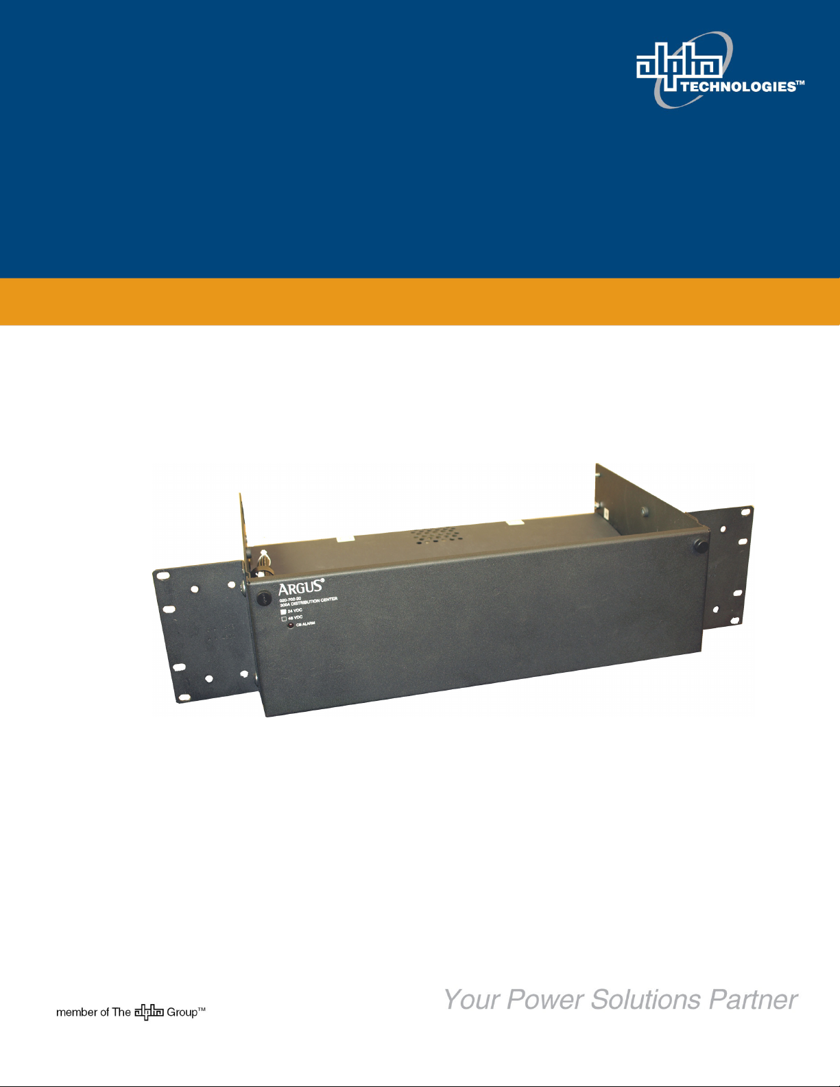
DCP03 300A Distribution Center
Installation & Operation Manual
XXX-XX
Page 2

This page is intentionally left blank.
Page 3

DCP03 300A Distribution Center
020-702-B2
The following documents and drawings are included in this manual:
• Specifications: 020-702-B1
• Installation and Operation Instructions 020-702-C0
• Customer connection drawing: 020-702-08
• Outline drawing: 020-702-06
• Schematic 020-702-05
Alpha Technologies Ltd. 020-702-B2 Rev C WC
Printed in Canada. © 2010 Alpha Technologies Ltd. ALPHA and CORDEX are trademarks of Alpha Technologies Ltd. All Rights
Reserved.
Page 4

IMPORTANT SAFETY INSTRUCTIONS
SAVE THESE INSTRUCTIONS
1. Please read this manual prior to use to become familiar with the product’s numerous features and operating
procedures. To obtain a maximum degree of safety, follow the sequences as outlined.
2. This manual provides warnings and special notes for the user:
a. Points that are vital to the proper operation of the product or the safety of the operator are
indicated by the heading: WARNING.
b. A notation that is in Bold or Italic typeface covers points that are important to the
performance or ease of use of the product.
3. Before using the product, read all instructions and cautionary markings on the product and any equipment
connected to the product.
4. Do not expose the product to rain or snow; install only in a clean, dry environment.
5. CAUTION – Unless otherwise noted, use of an attachment not recommended or sold by the product
manufacturer can result in a risk of fire, electric shock, or injury to persons.
6. CAUTION – Do not operate the product if it has received a sharp blow, it has been dropped, or otherwise
damaged in any way – return it to a qualified service center for repair.
7. CAUTION – Do not disassemble the product – call our qualified service centers for servicing. Incorrect
reassembling can result in a risk of electrical shock or fire.
8. WARNING – Use care working around battery systems. Before unpacking and handling batteries, thoroughly
read and follow the documentation from the battery manufacturer with special regard to safety precautions.
9. WARNING – Under abnormal operating conditions, or as a result of damage and/or misuse of a battery,
potentially hazardous conditions could occur including burns from sulphuric acid or injury from explosive
gases.
10. WARNING – Whenever working with batteries there is a short-circuit current hazard. Extreme caution must
be taken to prevent electrical arcing, electrical burns or shock.
Page 5

TABLE OF CONTENTS
1 INTRODUCTION ............................................................................................................................................................. 1
1.1 Scope of the Manual ..................................................................................................................................... 1
1.2 Product Overview .......................................................................................................................................... 1
1.3 Part Numbers and List Options ..................................................................................................................... 2
2 DISTRIBUTION CENTER FEATURES ................................................................................................................................ 3
2.1 Distribution Configurations ............................................................................................................................ 3
2.2 Low Voltage Disconnect (LVD) ..................................................................................................................... 3
2.3 Shunt ............................................................................................................................................................. 3
2.4 Internal Alarm Card ....................................................................................................................................... 4
2.5 CXCI I/O Terminal Block (Option) ................................................................................................................. 4
2.6 CXCM2 I/O Terminal Block (Option) ............................................................................................................. 5
2.7 4R/8D ADIO or 8R/8D 8DIO (Option) ........................................................................................................... 5
3 INSPECTION.................................................................................................................................................................. 7
3.1 Packing Materials .......................................................................................................................................... 7
3.2 Check for Damage ........................................................................................................................................ 7
4 INSTALLATION .............................................................................................................................................................. 8
4.1 Safety Precautions ........................................................................................................................................ 8
4.2 Tools Required .............................................................................................................................................. 8
4.3 Preparation/Mounting .................................................................................................................................... 8
4.4 Breaker Installation ....................................................................................................................................... 9
4.5 Breaker Removal .......................................................................................................................................... 9
5 WIRING ...................................................................................................................................................................... 10
5.1 Calculating Output Wire Size Requirements............................................................................................... 10
5.2 System and Battery Connections ................................................................................................................ 10
5.3 Alarm Connections ...................................................................................................................................... 12
5.4 Grounding ................................................................................................................................................... 12
5.5 CAN Serial Ports (4R/8D ADIO or 8R/8D 8ADIO Option) .......................................................................... 13
6 SYSTEM STARTUP ...................................................................................................................................................... 14
6.1 Check System Connections ........................................................................................................................ 14
6.2 Verify AC and Power the Rectifier Shelf ..................................................................................................... 14
6.3 Check Battery Polarity and Connect ........................................................................................................... 14
6.4 CXC Reset .................................................................................................................................................. 14
7 MAINTENANCE ........................................................................................................................................................... 15
8 ACRONYMS AND DEFINITIONS ..................................................................................................................................... 16
i
Page 6

This page is intentionally left blank.
Page 7
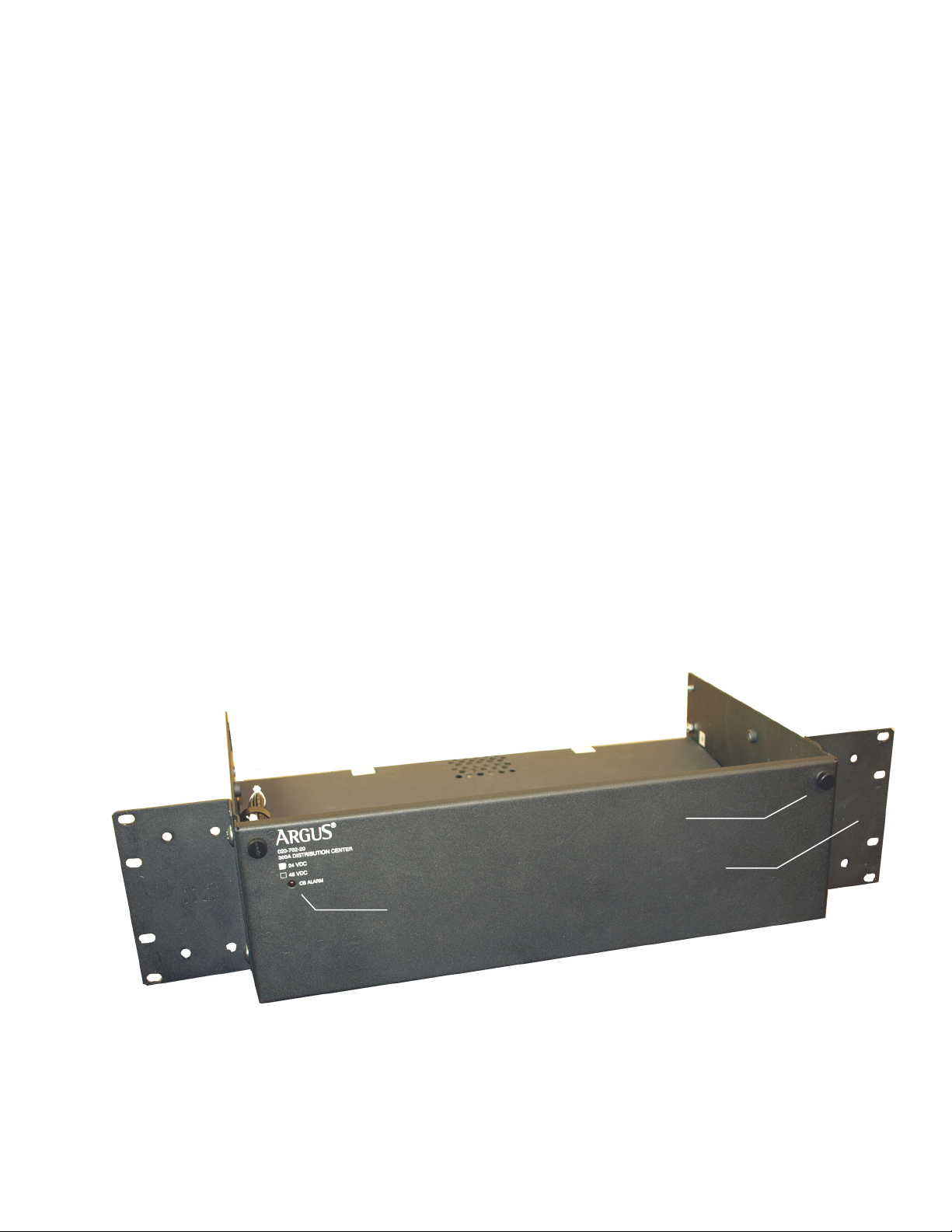
Breaker Trip LED
Door securing knob
Universal mounting bracket
1 Introduction
1.1 Scope of the Manual
This instruction manual covers the features and installation of Alpha Technologies DCP03 300A Distribution
Center.
NOTE: To aid the user with installation, frequent reference is made to drawings located at the rear of this manual.
1.2 Product Overview
The DCP03 300A Distribution Center is an integrated DC system distribution package designed for small to midsized power applications.
The compact unit installs in three rack units of space. The design allows for front access to DC and signal
connections after installation.
All distribution wires are connected via two-hole termination lugs.
Up to 18 plug-in breakers can be installed at up to 100A per position. As an option, the system can be configured
with 4 battery breaker and 14 load breaker positions. Optional multiple pole breaker adapter kits are also
available.
Current shunts and low voltage disconnects (LVDs) can be installed as options.
The DCP03 also includes options for mounting CXCI and CXCM2 controller I/O terminal blocks behind the front
door of the distribution center. This allows for front access connections to controller I/O when using the
distribution center with Cordex 1.8kW rectifiers and integrated controllers.
In addition, the 4R/8D ADIO or 8R/8D 8DIO Cordex peripherals can be installed in the front door expanding the
I/O capabilities of the CXC system controller.
The DCP03 has rear bus bars for rectifier input for either cabling or bus bar connections for fast system
integration with Cordex 1.8kW rectifiers.
NOTE: Refer also to the manuals supplied for the individual modules within the system for further definition of features;
for example, details of controller operation are provided in the current version software manual.
020-702-C0 Rev C WC Page 1 of 16
Figure 1–Front angle view of the DCP03 300A Distribution Center
Page 8

1.3 Part Numbers and List Options
This product is available to order under the following part numbers and list options:
Description Part Number/List Option
DCP03 300A Distribution Center (18-position) ............................................................................................................. 020-702-20
Basic unit ............................................................................................................................................................................. *List 0
24 Volt, negative ground ..................................................................................................................................................... List 1,4
48 Volt .................................................................................................................................................................................... List 2
19” center mount .................................................................................................................................................................. List 19
19” flush mount .................................................................................................................................................................... List 21
23” center mount .................................................................................................................................................................. List 23
23” flush mount .................................................................................................................................................................... List 25
Charcoal finish with white (contrasting) silkscreen ............................................................................................................. *List 56
24Vdc LVD (for List 1,4 only) ............................................................................................................................................ **List 71
48Vdc LVD (for List 2 only) ............................................................................................................................................... **List 72
CXCI I/O Interface ............................................................................................................................................................. **List 74
CXCM2 I/O Interface ......................................................................................................................................................... **List 75
4R/8D ADIO (requires List 74) ............................................................................................................................................. List 79
8R/8D 8DIO (requires List 74) .............................................................................................................................................. List 80
Jumper, no shunt (when L84 not equipped) ......................................................................................................................... List 81
Jumper, no LVD (when L71/72 not equipped) ...................................................................................................................... List 82
400A shunt (not available for 24Vdc CXCI) .......................................................................................................................... List 84
18 load breaker positions ..................................................................................................................................................... List 87
4 battery and 14 load breaker positions ............................................................................................................................. *List 88
Top cover ........................................................................................................................................................................... *List 93
* Default option ** Mutually exclusive, consult factory
This product is compatible with following options:
Description Part Number
Bus bar, 300A UDC to single 19" or 23" 1.8kW shelf (2x required per system) ........................................................... 614-840-13
Bus bar, 300A UDC to dual 19" 1.8kW shelves (2x required per system) .................................................................... 614-841-13
Kydex cover kit, for 300A UDC and single 19" or 23" 1.8kW shelf .............................................................................. 037-202-20
Kydex cover kit, for 300A UDC and dual 19" 1.8kW shelves ....................................................................................... 037-207-20
Breaker, AM-type mid-trip plug-in, 1A .......................................................................................................................... 470-300-10
Breaker, AM-type mid-trip plug-in, 3A .......................................................................................................................... 470-301-10
Breaker, AM-type mid-trip plug-in, 5A .......................................................................................................................... 470-302-10
Breaker, AM-type mid-trip plug-in, 10A ........................................................................................................................ 470-303-10
Breaker, AM-type mid-trip plug-in, 15A ........................................................................................................................ 470-304-10
Breaker, AM-type mid-trip plug-in, 20A ........................................................................................................................ 470-305-10
Breaker, AM-type mid-trip plug-in, 25A ........................................................................................................................ 470-306-10
Breaker, AM-type mid-trip plug-in, 30A ........................................................................................................................ 470-307-10
Breaker, AM-type mid-trip plug-in, 35A ........................................................................................................................ 470-308-10
Breaker, AM-type mid-trip plug-in, 40A ........................................................................................................................ 470-309-10
Breaker, AM-type mid-trip plug-in, 45A ........................................................................................................................ 470-310-10
Breaker, AM-type mid-trip plug-in, 50A ........................................................................................................................ 470-311-10
Breaker, AM-type mid-trip plug-in, 60A ........................................................................................................................ 470-312-10
Breaker, AM-type mid-trip plug-in, 70A ........................................................................................................................ 470-313-10
Breaker, AM-type mid-trip plug-in, 80A ........................................................................................................................ 470-314-10
Breaker, AM-type mid-trip plug-in, 90A ........................................................................................................................ 470-315-10
Breaker, AM-type mid-trip plug-in, 100A ...................................................................................................................... 470-316-10
Load breaker kit, AM-type mid-trip plug-in, 125A (2-pole) ............................................................................................ 747-523-20
Load breaker kit, AM-type mid-trip plug-in, 150A (2-pole) ............................................................................................ 747-524-20
Load breaker kit, AM-type mid-trip plug-in, 175A (3-pole) ............................................................................................ 747-525-20
Load breaker kit, AM-type mid-trip plug-in, 200A (3-pole) ............................................................................................ 747-526-20
Load breaker kit, AM-type mid-trip plug-in, 250A (3-pole) ............................................................................................ 747-527-20
Battery breaker, AM-type series-trip plug-in, 100A ....................................................................................................... 470-347-10
Battery breaker kit, AM-type series-trip plug-in, 150A (2-pole) ..................................................................................... 747-503-20
Battery breaker kit, AM-type series-trip plug-in, 250A (3-pole) ..................................................................................... 747-504-20
The above information is valid at the time of publication. Consult factory for up-to-date ordering information.
020-702-C0 Rev C WC Page 2 of 16
Page 9
Load breaker
2 Distribution Center Features
2.1 Distribution Configurations
The DCP03 contains 18 total AM-type plug-in breaker positions with two-hole connection points for both breaker
output and the ground return bus. The breaker distribution can be configured one of two ways:
1. List 87 configuration provides for all 18 positions to be dedicated to load distribution. In this configuration, both
rectifier and battery connections must be made on the rear bus bar input or external to the distribution center.
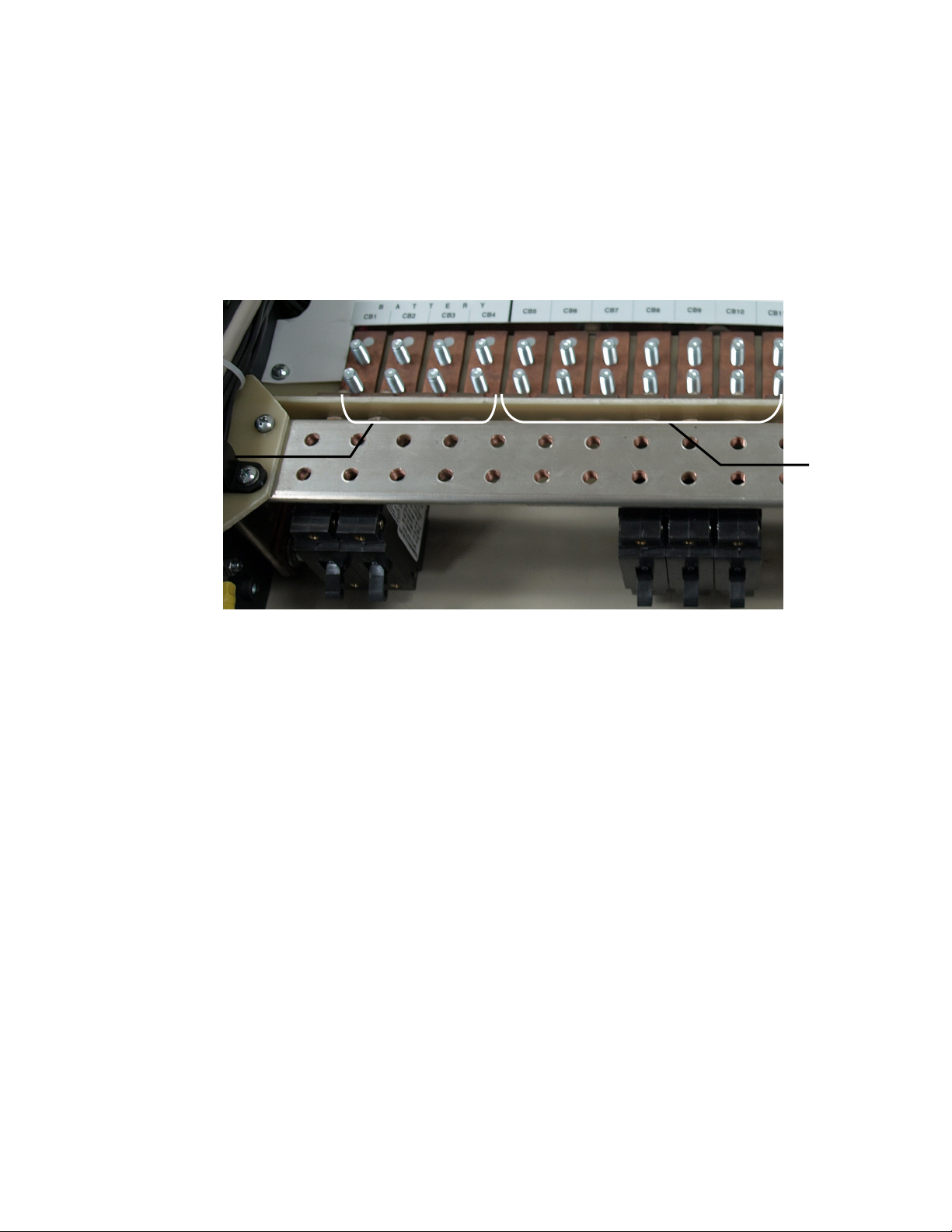
2. List 88 configuration allows for 4 battery breaker and 14 load breaker positions as shown below:
Battery breaker
connections
connections
Figure 2–DCP03 configured for 4 battery and 14 load breakers
NOTE: Load breakers require mid-trip AM plug-In breakers, and battery breakers require series-trip AM plug-In breakers.
NOTE: When there is no power on the rectifiers and there is only one battery circuit breaker, there will be no alarm if the
circuit breaker trips.
2.2 Low Voltage Disconnect (LVD)
An optional 400A LVD can be installed for both 48Vdc and 24Vdc system configurations. If the system is
configured with 18 load breakers, the LVD will be installed in series with the load (LVLD). If the system is
configured with 4 battery and 14 load breakers, the LVD will be installed in series with the batteries (LVBD).
If an LVD is not equipped, the system must be provisioned with a jumper to bypass the LVD position (List 82).
2.3 Shunt
An optional 400A shunt can be installed for system current measurement. If the system is configured with 18 load
breakers, the shunt will be installed in series with the load. If the system is configured with 4 battery and 14 load
breakers, the shunt will be installed in series with the batteries.
NOTE: Shunt option requires 48V option (List 2) when used with CXCI.
NOTE: Shunt option is not available for 24V option when used with CXCI.
020-702-C0 Rev C WC Page 3 of 16
If a shunt is not equipped, the system must be provisioned with a jumper to bypass the shunt position (List 81).
Page 10
LVD override switch
I/O customer connection points
2.4 Internal Alarm Card
The DCP03 includes a standard alarm card providing a common interface point to internal system I/O
connections, an LVD override switch, and LED indication of breaker trip.
The alarm card provides terminal block access to internal signals such as binary alarms for breaker trip & LVD
open, alarm relay for driving LVD, and analog inputs for current (shunt) and voltage measurements. The terminal
blocks provide a single point of access to these signals for connecting to an external system controller. Refer to
the customer connections (020–702–08) drawing at the rear of this manual for details on terminal block
assignments.
The LVD override switch provides the user with the ability to inhibit or override LVD contactor operation as a
safeguard during controller maintenance. A green LED signals when the LVD is in normal operation mode and a
yellow LED signals when the switch has been placed into the override position.
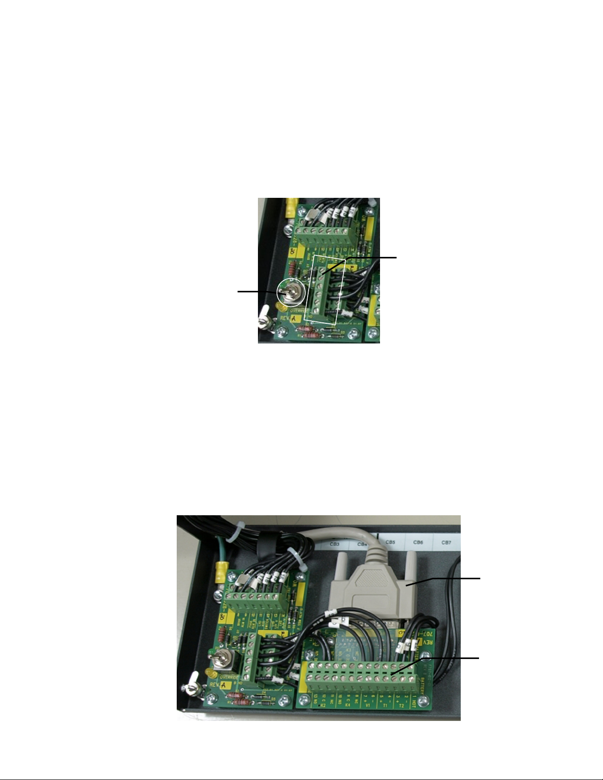
2.5 CXCI I/O Terminal Block (Option)
When using the DCP03 as a distribution solution for use with a 1.8kW rectifier shelf with integrated CXCI
controller, an I/O terminal block can be installed in the UDC front door for front access to controller signals.
The CXCI terminal block kit comes with a 25-pin D-sub wire harness for connection to the back of the 1.8kW
rectifier shelf using the CXCI controller. Refer to the manual for the 1.8kW rectifier shelf (or system).
The internal signals from the distribution center are wired to the CXCI I/O board direct from the internal alarm
board. The remaining relay outputs, digital inputs, and analog inputs are available on the board via terminal
blocks for customer connection of external signals. Refer to the customer connections (020–702–08) drawing at
the rear of this manual for details on terminal block assignments.
Figure 3–Internal alarm card
D-sub wire harnesses
to 1.8kW shelf
020-702-C0 Rev C WC Page 4 of 16
CXCI I/O terminal
block assembly
Page 11
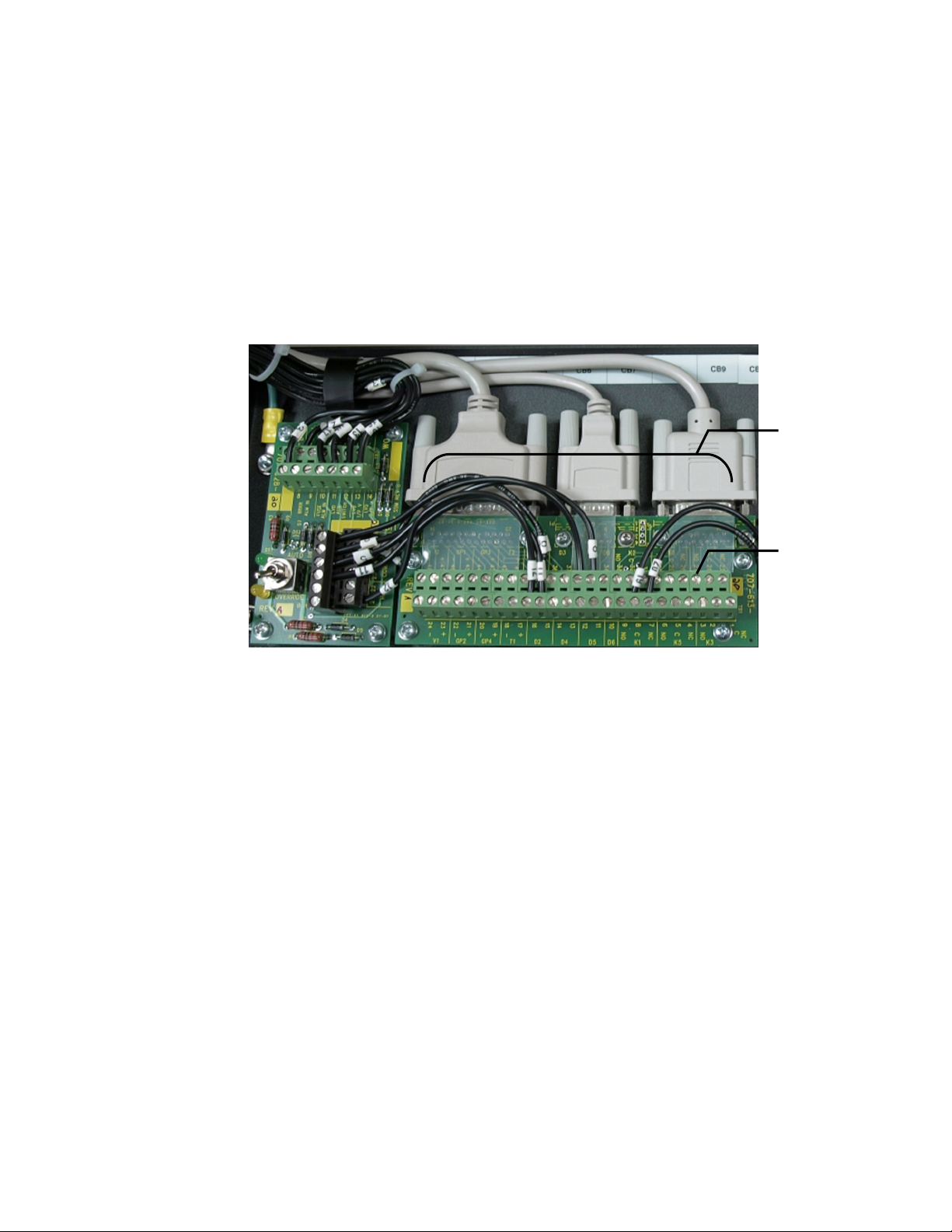
DB-style cable
connections to
Figure 4–Internal alarm card and CXCI I/O terminal block option
2.6 CXCM2 I/O Terminal Block (Option)
When using the DCP03 as a distribution solution for use with a 1.8kW rectifier shelf with a modular CXCM2
controller, an I/O terminal block can be installed in the UDC front door for front access to controller signals.
The CXCM2 terminal block kit comes with 25-pin, 15-pin, and 9-pin D-sub wire harnesses for connection to the
back of the 1.8kW rectifier shelf using the CXCM2 controller. Refer to the manual for the 1.8kW rectifier shelf (or
system).
The internal signals from the distribution center are wired to the CXCM2 I/O board direct from the internal alarm
board. The remaining relay outputs, digital inputs, and analog inputs are available on the board via terminal
blocks for customer connection of external signals. Refer to the customer connections (020–702–08) drawing at
the rear of this manual for details on terminal block assignments.
1.8kW shelf
CXCM2 I/O
terminal block
assembly
Figure 5–Internal alarm card and CXCM2 I/O terminal block option
2.7 4R/8D ADIO or 8R/8D 8DIO (Option)
The 4R/8D ADIO or 8R/8D 8DIO Cordex peripheral can also be installed on the front door of the DCP03. The
4R/8D ADIO option expands the I/O capability of an existing Cordex controller by adding an additional 4 relays
outputs and 8 digital inputs. The 8R/8D 8DIO option expands the I/O capability of an existing Cordex controller by
adding an additional 8 relays outputs and 8 digital inputs.
The 4R/8D ADIO or 8R/8D 8DIO peripheral installs on the right side of the front door. They connect to the Cordex
system via CAN communications using RJ-12 offset communications cables.
All I/O connections are made via screw terminal blocks. Refer to the customer connections (020–702–08) drawing
at the rear of this manual for details on terminal block assignments.
NOTE: The 4R/8D ADIO option and the 8R/8D 8DIO option cannot be used in the same configuration with the CXCM2
I/O terminal block assembly. For applications requiring CXCM2 and ADIO/ 8DIO, one of the two devices must be
mounted externally to the distribution center. Consult factory for options.
020-702-C0 Rev C WC Page 5 of 16
Page 12
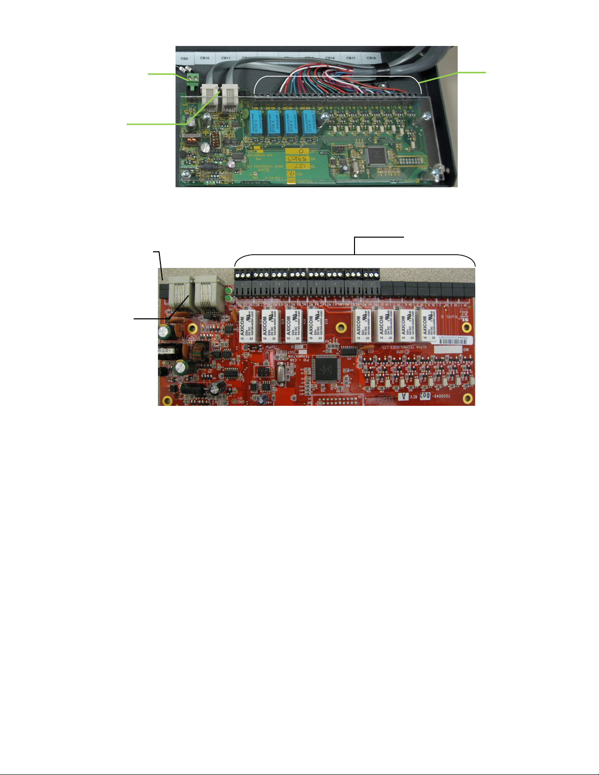
ADIO power supply
Customer I/O
terminal blocks
Customer I/O
connection
CAN in/out
connections via
terminal blocks
Figure 6–4R/8D ADIO option
8DIO power
supply connection
CAN in/out
connections via
Figure 7–8R/8D 8DIO option
020-702-C0 Rev C WC Page 6 of 16
Page 13

3 Inspection
3.1 Packing Materials
All Alpha products are shipped in rugged, double walled boxes and suspended via solid inserts to minimize shock
that can occur during transportation. Packaging assemblies and methods are tested to International Safe Transit
Association standards.
Products are also packaged with Cortex. This plastic wrap contains a corrosive-inhibitor that protects the product
from corrosion for up to two years.
3.1.1 Returns for Service
Save the original shipping container. If the product needs to be returned for service, it should be packaged in its
original shipping container. If the original container is unavailable, make sure the product is packed with at least
three inches of shock-absorbing material to prevent shipping damage.
NOTE: Alpha Technologies is not responsible for damage caused by the improper packaging of returned products.
3.2 Check for Damage
Prior to unpacking the product, note any damage to the shipping container. Unpack the product and inspect the
exterior for damage. If any damage is observed contact the carrier immediately.
Continue the inspection for any internal damage. In the unlikely event of internal damage, please inform the
carrier and contact Alpha Technologies for advice on the impact of any damage.
Verify that you have all the necessary parts per your order for proper assembly.
020-702-C0 Rev C WC Page 7 of 16
Page 14

4 Installation
This chapter is provided for qualified personnel to install the product, which shall be mounted in a clean and dry
environment. For battery installation refer to the manufacturer’s guidelines for more specific information.
NOTE: To aid the user with installation, frequent reference is made to drawings located at the rear of this manual.
4.1 Safety Precautions
DANGER
Hazardous voltages are present at both the input and the output of power systems. The DC output
from the rectifiers and the battery system is at a lethal potential and has a high short circuit
current capacity that can cause electrocution, severe burns and electrical arcing.
CAUTION
Circuit breaker must be off before removal or insertion.
Before working with any live battery or power system/distribution center, follow these precautions:
• Remove all metallic jewelry; e.g., watches, rings, metal rimmed glasses, necklaces.
• Wear safety glasses with side shields (and prescription lenses if necessary) at all times during installation.
The installer should follow all applicable local rules and regulations for electrical and battery installations; e.g.,
CSA, UL, CEC, NEC, OSHA, and local fire codes.
Use OSHA approved insulated hand tools.
4.2 Tools Required
Various insulated tools are essential for product installation. Use this list as a guide:
• Philips head screwdriver, #3 (tip size 1/4")
• Slot head screwdriver (blade size 1/8")
• 7/16" hex socket with drive
• 9/16" hex socket with drive
• Digital voltmeter equipped with test leads
• Cutters and wire strippers #16 to #26 AWG (1.5 to 0.14mm²).
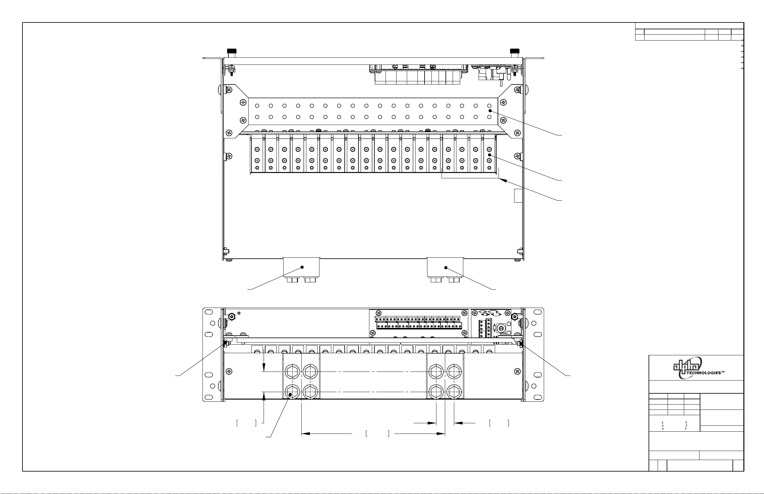
4.3 Preparation/Mounting
The DCP03 300A Distribution Center occupies three (3) vertical rack spaces. The rack mounting “ears” are
universal for 19" or 23" racks and can be center or flush mounted. See drawing 020-702-06.
Position the ears as desired and secure the DCP03 to the rack using at least three #12-24x1/2" screws on each
side. A captive type of drive, such as the Philips head, is preferred to reduce the possibility of slippage and
scratching of the unit’s exterior.
NOTE: The DCP03 requires at least 1RU (1.75") of space above the unit for tooling access to the load breaker ground
connections. Ensure that at least 1RU of space is open in the relay rack above the DCP03.
020-702-C0 Rev C WC Page 8 of 16
Page 15

4.4 Breaker Installation
1. Ensure mid-trip breakers are used for load and series-trip breakers are used for battery connections.
2. Turn breaker off.
3. Ensure that the breaker is right side up.
4. Align the breaker terminals with the correct holes.
5. Carefully push the breaker into position.
4.5 Breaker Removal
1. Turn breaker off.
2. Carefully pull the breaker out of position.
020-702-C0 Rev C WC Page 9 of 16
Page 16

5 Wiring
This chapter provides cabling details and notes on cable sizing for DC applications with respect to the product.
WARNING
Ensure that power is removed by turning off rectifiers and removing battery line fuse or
connection before attempting work on the wiring connections. Use a voltmeter to verify the
absence of voltage. Clearly mark the correct polarity of the battery leads before commencing work
on DC connections.
Refer to the previous (Installation) chapter for safety precautions and tools required.
CAUTION –When wiring the terminal blocks, take care to bundle and route the wires so they do not interfere with the
circuit breakers. Loose wires may cause the breakers to trip..
5.1 Calculating Output Wire Size Requirements
Wire size is calculated by first determining the appropriate maximum voltage drop requirement. Using the formula
below calculate the CMA wire size requirement. Determine the size and number of conductors required to satisfy
the CMA requirement.
CMA = (A x LF x K) / AVD, where:
CMA = Cross section of wire in circular mil area
A = Ultimate drain in amps
LF = Conductor loop feet
K = 11.1 constant factor for commercial (TW type) copper wire
AVD = Allowable voltage drop
Check again that the ampacity rating of the cable meets the requirement for the installation application. Consult
local electrical codes (NEC, CEC, etc.) for guidelines. If required, increase the size of the cable to meet the code.
5.2 System and Battery Connections
WARNING
Ensure the correct polarity is used for all cable terminations.
Refer to guidelines supplied with the load equipment. Typically distribution cables are sized to provide a 0.5V loop
drop at full load as well as meeting ampacity requirements of the protection fuse or circuit breaker.
Battery cables should be sized for a 0.25V drop from battery to the power system at full load including anticipated
growth. The cables should also meet ampacity requirements. Cables terminating directly on battery posts or
connection details should be secured so that there is no stress on the battery posts. Lead plated lugs and lead
plated or stainless steel hardware should be used on all terminations at vented batteries to reduce corrosion.
Prepare, route and connect cables from power system to battery termination details. Terminating points should be
burnished and a corrosion-inhibiting agent, such as NO-OX-ID “A”, should be applied to all battery terminal
connections.
NOTE: Final connection to battery live should not be made, insulate and leave disconnected or remove the battery fuses.
Switch battery contactors off (if used). See system startup procedure before connecting batteries online.
5.2.1 DC Input to Panel
The DCP03 contains bus bar input for hot and return connections. The bus bar contains 2 sets of 3/8" on 1"
center holes for bus bar or cable connection. The input bars are offset from the rear of the panel to allow for backto-back lug connections when cabling. If the DCP03 is configured for 18 load breakers (List 87), these
connections points must be used for connecting external batteries.
The system hot input is located on the left side of the DCP03 (when looking at the rear of panel) and the system
return is located on the right side. Refer toFigure 8.
020-702-C0 Rev C WC Page 10 of 16
Page 17

DCP03 input bar (return)
DCP03 input bar (hot)
Load breaker (hot) connection
Battery (hot) connection
NOTE: Bus bar inputs are fixed for hot and return placement. Labels indicating polarity will be reversed when configured
for 48Vdc positive ground versus 24Vdc negative ground.
Figure 8–Rear view of DCP03 bus bar input
5.2.2 Distribution Cabling
Refer to guidelines supplied with the load equipment. Typically distribution cables are sized to provide a 0.5V loop
drop at full load as well as meeting ampacity requirements of the protection fuse or circuit breaker.
Distribution cabling must be terminated with 1/4"–5/8"C lugs for connecting to DCP03.
5.2.3 Breaker Output (Hot) Connections
Connect breaker (hot) output connections before connecting the breaker returns. Secure two hole lugs to the 1/4"
studs (on 5/8" centers) using the supplied hardware with the DCP03. Cables should run directly out the rear of the
distribution center. Refer to Figure 9.
5.2.4 Breaker Return (Ground) Connections
Connect breaker (ground) output connections to the DCP03 ground bar. Secure two hole lugs to the 1/4" holes
(on 5/8" centers) using the supplied hardware with the DCP03. Cables should run directly out the rear of the
distribution center above the breaker (hot) output cables. Refer to Figure 9.
5.2.5 Battery Breaker Connections (List 88 Configuration)
Connect battery breaker (hot) connections first using same guidelines as the load cable installation. Connect
battery ground connections using same guidelines as load returns. Cables should run directly out the rear of the
distribution center above the breaker (hot) output cables. Refer to Figure 9.
020-702-C0 Rev C WC Page 11 of 16
System return (ground) bar
Figure 9–Battery, load, and return connection locations (List 88 configuration shown)
Page 18

System Internal and
or 8R/8D 8DIO
5.3 Alarm Connections
Terminal blocks can accommodate wire sizes #16 to #26 AWG (1.5 to 0.14mm²).
Route via wire-ways and use existing cable clamps to secure to existing (factory) wire harness along with
customer run signal wires. Ensure signal wires are routed along hinge point of front door so door opening and
closing won’t require excess wire slack. Refer to Figure 10 for wire routing example.
Terminal block connections for the internal alarm card, CXCI I/O, or CXCM2 I/O should be routed along the left
side of the DCP03 (looking at unit from front). Connections to the 4R/8D should be routed along the right hand
side of the DCP03. Refer to the customer connections (020-702-08) drawing at the rear of this manual for details
on terminal block assignments.
4R/8D ADIO or 8R/8D 8DIO wire routing
Cable clamp
5.4 Grounding
The isolated distribution center battery return bus (BRB) should be connected to the building master ground bus
(MGB) or floor ground bus (FGB) in a larger building. This acts as a system reference and as a low impedance
path to ground for surges, transients, noise, etc. The MGB or FGB should have a direct low impedance path to
the building grounding system. The cable from the distribution center to the MGB or FGB should be sized to
provide sufficient ampacity to clear the largest fuse or breaker on the distribution center, excluding the battery
protection fuse or circuit breaker. This is the minimum requirement; other factors including length of cable and
special grounding requirements of the load should also be factored in. The insulated cable should be equipped
with two-hole crimp type lugs and should not have any tight bends or kinks.
CXCI wire routing
4R/8D ADIO
CAN ports
Figure 10–DCP03 wire routing example (List 74 and 79 shown)
(Photo is for reference only – subject to installation requirements)
5.4.1 Frame Ground
020-702-C0 Rev C WC Page 12 of 16
The distribution center frame must also be connected to the MGB or FGB. This is done for personnel safety and
to meet many Telco grounding requirements. Each bay should have its own frame ground connection. The
minimum recommended wire size is #2 AWG (35mm²).
The DCP03 is grounded utilizing screws/bonding washers to the relay rack then to the main grounding bus using
#2 AWG (35mm²) insulated cable.
Page 19

5.5 CAN Serial Ports (4R/8D ADIO or 8R/8D 8ADIO Option)
Two CAN Serial ports (modular jacks with offset latches), for communications with Alpha’ Cordex rectifiers and
other CAN-enabled equipment (nodes) on the same system, are located on the optional 4R/8D ADIO or 8R/8D
8ADIO Cordex peripherals (Figure 10).
Daisy-chain from node to node (CAN OUT of one shelf to CAN IN of another) as necessary and ensure that only
the last shelf is terminated as follows:
5.5.1 CAN Termination
A CAN termination jumper is located beside the CAN ports. See the customer connections drawing for your shelf.
The CAN bus may be OPEN to the next node in the system or TERMINATED on the final node on the CAN bus.
020-702-C0 Rev C WC Page 13 of 16
Page 20

6 System Startup
Visually inspect the installation thoroughly.
After completing the system installation and power system wiring, perform the following startup and test
procedure to ensure proper operation:
6.1 Check System Connections
• Ensure AC is off, battery is disconnected, and all power modules are removed from the shelf.
• Triple-check the polarity of all connections.
6.2 Verify AC and Power the Rectifier Shelf
• Install one power module.
• Verify AC input voltage is correct and turn on the corresponding feeder breaker.
• The power module OK LED should illuminate after a preset start delay.
• Using the CXC, test functionality of various module alarms and controls.
6.3 Check Battery Polarity and Connect
• Verify correct battery polarity using a voltmeter (ensuring no cells or batteries are reversed).
• Connect battery as required to the output of the system.
• Install remaining power modules.
• In the adjustments menu of the CXC, set float and equalize voltage to the levels specified by the battery
manufacturer.
• Using the CXC, test functionality of various module alarms and controls. In addition, perform a load test with
the system using a resistive load box as needed.
• Enable the temperature compensation (temp comp) feature (Batteries menu) and program the settings for
slope and breakpoints (upper and lower) with respect to the specific batteries used.
6.4 CXC Reset
The reset button located on the front panel of the optional CXC is for restarting the microprocessor. When
pressed momentarily, the unit beeps twice then resets. The front-panel LEDs illuminate temporarily, but will
extinguish after the system has finished its 15-second self-test.
WARNING
Before removing a CXC from a live system, or performing controller maintenance, an external LVD
inhibit (or override) is required to avoid a disruption of service.
The LVD Control functions can be hardwired directly from the assigned relay output to an optional front panel LVD
override control.
Place the LVD Control switch to the INHIBIT position to keep the LVD contactor engaged.
WARNING
Do not leave the switch in the INHIBIT position. Doing so can result in a complete discharge of the
batteries during a power failure situation.
To allow the CXC to resume automatic control of the LVD contactor, check that the AUTO IN (green) LED is lit
confirming that the CXC will keep the LVD contactor engaged. Then you can return the LVD Control switch to
the AUTO IN position.
Canada and USA toll free 24 hour emergency technical support: +1 888 462 7497.
020-702-C0 Rev C WC Page 14 of 16
Page 21

7 Maintenance
Although very little maintenance is required with Alpha systems, routine checks and adjustments are
recommended to ensure optimum system performance. Qualified service personnel should do repairs.
The following table lists a few maintenance procedures for this system. These procedures should be performed at
least once a year.
WARNING: HIGH VOLTAGE AND SHOCK HAZARD.
Use extreme care when working inside the unit while the system is energized.
Do not make contact with live components or parts.
Ensure redundant modules or batteries are used to eliminate the threat of service interruptions
while performing maintenance on the system’s alarms and control settings.
Procedure Date Completed
Clean ventilation openings
Inspect all system connections (re-torque as necessary)
Verify alarm/control settings
Verify alarm relay operation
Table A–Sample maintenance log
Consult factory for replacement parts.
To order more breakers refer to the options listed in the Specifications Section at the front of this manual. Always
replace circuit breakers with the same type and rating.
020-702-C0 Rev C WC Page 15 of 16
Page 22

8 Acronyms and Definitions
AC Alternating current
AWG American wire gauge
CEC Canadian Electrical Code
CMA Circular mil area
CSA Canadian Standards Association
CX Cordex series; e.g., CXC for Cordex™ System Controller
DC Direct current
DCP Distribution Center Plug-In
LVD Low voltage disconnect
LVBD Low voltage battery disconnect
LVLD Low voltage load disconnect
MIL One thousandth of an inch; used in expressing wire cross sectional area
NC Normally closed
NEC National Electrical Code (USA)
NO Normally open
OSHA Occupational Safety & Health Administration
UL Underwriters Laboratories
VRLA Valve regulated lead acid
020-702-C0 Rev C WC Page 16 of 16
Page 23

Specifications for Alpha Technologies DCP03 300A Distribution Center
System Output
Voltage: 24 or 48Vdc
Current: ≤300A (dc) m axim um
Distribution Breaker Ratings: 18-position, plug-in type (bullet terminals), AM-style, 5 to 100A
Connections
Load Connections: 18x sets 1/4”-20 studs on 5/8” centers (List 87)
14x sets 1/4”-20 studs on 5/8” centers (List 88)
[multiple pole breaker adapter: 3/8” holes on 1” centers]
Battery Terminations: 4x sets 1/4”-20 studs on 5/8” centers (List 88)
[multiple pole breaker adapter: 3/8” holes on 1” centers]
Rectifier Terminations: Hot: 2x sets 3/8” holes on 1” centers
Return: 2x sets 3/8” holes on 1” centers
Ground Bar: 18x sets 1/4” holes on 5/8” centers
Alarm Connections: #16 to #26 AWG (1.5 to 0.14mm
Communication: Terminal blocks: internal I/O
DB (serial) connection(s): optional CXCI and CXCM2 I/O
RJ-12 Offset: CAN for optional ADIO or 8DIO
Access: Front access after installation with 1RU required above panel for tooling
Miscellaneous
Size: 133mm H x 432mm W x 318mm D (5.23" H x 17.25" W x 12.5" D)
[does not include mounting brackets]
Mounting: 19” or 23”; flush or center (default)
Weight: 11.6 kg (25.6 lb.)
Environmental
Operating Temperature: -40°C to +65°C (-40°F to +149°F)
-40°C to +55°C (-40°F to +131°F) de-rated when L71 (24V LVD) equipped
Humidity: 10 to 95% non-condensing
Elevation: -500m to +4000m (-1640 feet to 13124 feet)
The above information is valid at the time of publication. Consult factory for up-to-date ordering information.
Specifications are subject to change without notice.
2
)
020-702-B1 Rev C WC
Page 24

Page 25

Page 26

Page 27

Page 28

Page 29

Page 30

Page 31

Page 32

17.25 438.1
16.8 426.7
317.9 TYP12.52
11.3 TYP287.0
LTR DESCRIPTION
REVISIONS
REV BY
APPDDATE
LIST 21 - 19" FLUSH MOUNTING
TOP VIEW
18.31
465.1
19.0 482.6
LIST 19/21 - 19" MOUNTING
FRONT VIEW
0
0.48 TYP12.2
5.23 132.8
4.99 126.7
95.03.74
37.81.49
6.10.24
0
c 2007 ARGUS TECHNOLOGIES
O
DIMENSIONS ARE IN INCHES WITH METRIC (mm) IN BRACKETS: INCHES [mm]
THESE DESIGNS AND SPECIFICATIONS ARE THE PROPERTY OF
ARGUS TECHNOLOGIES AND SHALL NOT BE COPIED OR USED
FOR MANUFACTURING WITHOUT ITS WRITTEN CONSENT.
0.04"
0.02"
RP
RP
RP 2007/09
JK 2007/09
[X]
[X.X] 0.5mm
[X.XX] 0.25mm
DESIGN
DRAWN
CHECKED
APPROVED
TOLERANCES
X.X
X.XX
X.XXX 0.01"
TITLE
2007/09
2007/09
1mm
MATERIAL
FINISH
PER P.O. and
Doc. 070-024-83
SCALE
ASSEMBLY, 300A FRONT
ACCESS UDC
ISSUE
DATE
SIZE
B
TYPE
D2
DWG NO.
SHEET
020-702-06
SEE B.O.M.
NTS
OF
1 2
REV
A
Page 33

317.9 TYP12.52
LTR DESCRIPTION
REVISIONS
REV BY
APPDDATE
287.0 TYP11.3
LIST 19 - 19" MOUNTING
LIST 23 - 23" MOUNTING
6.0 TYP152.4
0
0.48 TYP12.2
16.80 426.7
17.25 438.1
LIST 19/23 - CENTER MOUNTING
TOP VIEW
22.31 566.7
23.00 584.2
LIST 23 - 23" MOUNTING
FRONT VIEW
132.8
5.23
4.99
126.7
95.03.74
37.81.49
6.10.24
0
c 2007 ARGUS TECHNOLOGIES
DIMENSIONS ARE IN INCHES WITH METRIC (mm) IN BRACKETS: INCHES [mm]
THESE DESIGNS AND SPECIFICATIONS ARE THE PROPERTY OF
ARGUS TECHNOLOGIES AND SHALL NOT BE COPIED OR USED
FOR MANUFACTURING WITHOUT ITS WRITTEN CONSENT.
TITLE
SCALE
ASSEMBLY, 300A FRONT
ACCESS UDC
ISSUE
DATE
SIZE
B
TYPE
D2
DWG NO.
SHEET
020-702-06
NTS
OF
2 2
REV
A
Page 34
LTR DESCRIPTION
BJLMADDED LIST 80, 8R/8D 8DIO
BREAKER RETURNS
1/4-20 HARDWARE ON 5/8" CENTERS
BREAKER OUTPUTS
1/4-20 HARDWARE ON 5/8" CENTERS
BATTERY BREAKERS
(FOUR POSITIONS)
WHEN LIST 88 SPECIFIED
REVISIONS
REV BY
12/10
12/10
APPD
JK
CHASSIS GROUND
(10-32 STUD)
UDC INPUT BUS
1.125 28.58
3/8-16 HARDWARE
ON 1" CENTERS
TOP VIEW
203.208.0
REAR VIEW
UDC RETURN BUS
(RECTIFIER RETURN)(RECTIFIER HOT)
CHASSIS GROUND
(10-32 STUD)
TYP25.401.0
c 2007 ALPHA TECHNOLOGIES
O
DIMENSIONS ARE IN INCHES WITH METRIC (mm) IN BRACKETS: INCHES [mm]
THESE DESIGNS AND SPECIFICATIONS ARE THE PROPERTY OF
ARGUS TECHNOLOGIES AND SHALL NOT BE COPIED OR USED
FOR MANUFACTURING WITHOUT ITS WRITTEN CONSENT.
DESIGN
DRAWN
CHECKED
APPROVED
TOLERANCES
X.X
X.XX
X.XXX
TITLE
0.04"
0.02"
0.01"
RP
RP
RP
JK
[X] 1mm
[X.X] 0.5mm
[X.XX]
2007/09
2007/09
2007/09
2007/09
0.25mm
MATERIAL
FINISH
PER P.O. and
Doc. 070-024-83
SCALE
CUSTOMER CONNECTION
300A FRONT ACCESS UDC
ISSUE
DATE
SIZE
B
TYPE
D2
DWG NO.
SHEET
1 4
020-702-08
SEE B.O.M.
NTS
OF
REV
B
Page 35
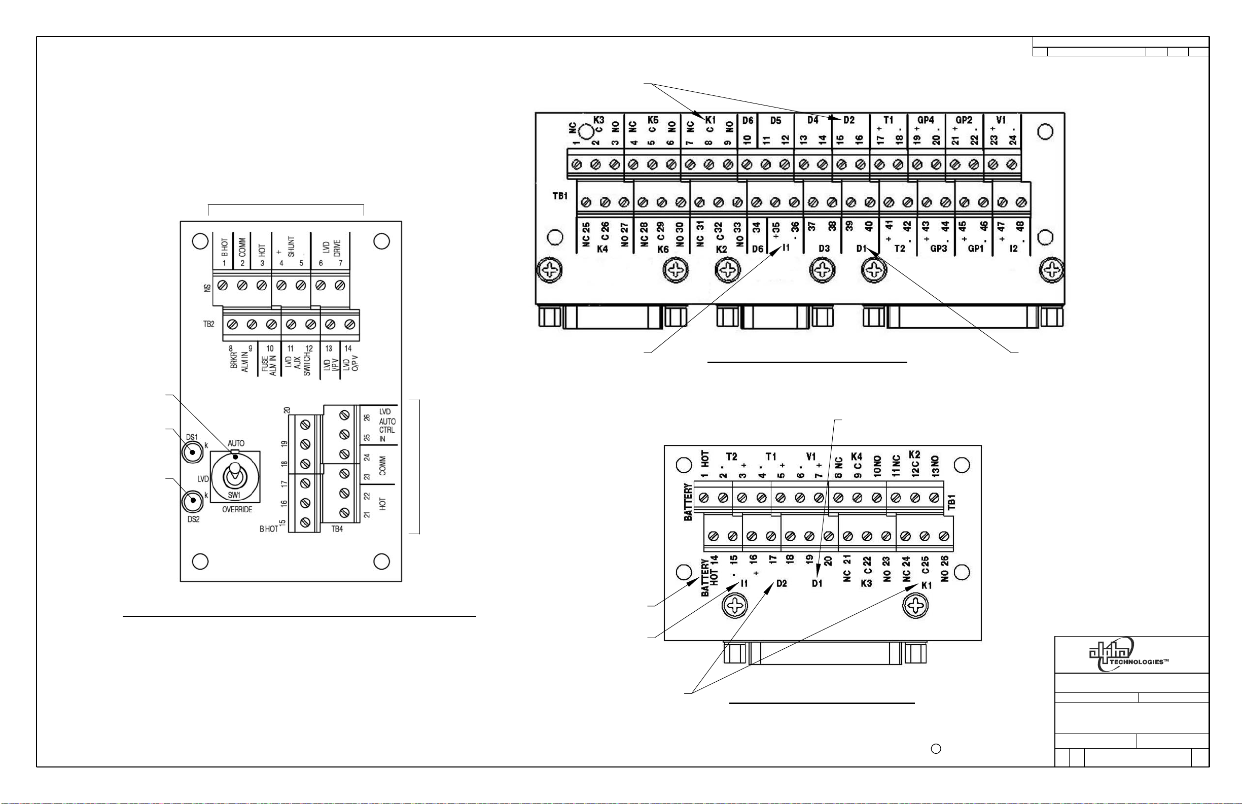
USED INTERNALLY WHEN
LIST 74 OR 75 EQUIPPED
USED INTERNALLY WHEN
LIST 71 OR 72 EQUIPPED
LTR DESCRIPTION
REVISIONS
REV BY
APPDDATE
LVD OVERRIDE SWTICH
GREEN LVD AUTO
CONTROL LED
YELLOW LVD
OVERRIDE LED
LIST 1,4 OR 2 - LVD OVERRIDE / DISTRIBUTION ALARM PCB
USED INTERNALLY WHEN
USED INTERNALLY WHEN
LIST 74 OR 75 EQUIPPED
USED INTERNALLY WHEN
LIST 71 OR 72 BATTERY
USED INTERNALLY WHEN
LIST 84 EQUIPPED
LVD EQUIPPED
LIST 84 EQUIPPED
LIST 75 - CXCM2 INTERFACE PCB
USED INTERNALLY WHEN
LIST 74 OR 75 EQUIPPED
USED INTERNALLY WHEN
LIST 74 OR 75 EQUIPPED
USED INTERNALLY WHEN
LIST 71 OR 72 EQUIPPED
LIST 74 - CXCI INTERFACE PCB
c 2007 ALPHA TECHNOLOGIES
DIMENSIONS ARE IN INCHES WITH METRIC (mm) IN BRACKETS: INCHES [mm]
THESE DESIGNS AND SPECIFICATIONS ARE THE PROPERTY OF
ARGUS TECHNOLOGIES AND SHALL NOT BE COPIED OR USED
FOR MANUFACTURING WITHOUT ITS WRITTEN CONSENT.
TITLE
SCALE
CUSTOMER CONNECTION
300A FRONT ACCESS UDC
ISSUE
DATE
SIZE
B
TYPE
D2
DWG NO.
SHEET
2 4
020-702-08
NTS
OF
REV
B
Page 36

LIST 79 - 4 RELAY / 8 DIGITAL ADIO PCB
LTR DESCRIPTION
REVISIONS
REV BY
APPDDATE
JUMPER SETTINGS FOR
CAN TERMINATION
OUT
P10
IN
CAN IN RJ12 OFFSET
PIN OUT (J2)
GND1.
CAN H2.
NOT CONNECTED3.
CAN L4.
NOT CONNECTED5.
NOT CONNECTED 6.
DIMENSIONS ARE IN INCHES WITH METRIC (mm) IN BRACKETS: INCHES [mm]
IN
CAN OUT RJ12 OFFSET
PIN OUT (J1)
GND1.
CAN H2.
NOT CONNECTED3.
CAN L4.
NOT CONNECTED5.
NOT CONNECTED6.
OUT
-
+
POWERDIGITAL INPUTS RELAY OUTPUTS CAN
c 2007 ALPHA TECHNOLOGIES
THESE DESIGNS AND SPECIFICATIONS ARE THE PROPERTY OF
ARGUS TECHNOLOGIES AND SHALL NOT BE COPIED OR USED
FOR MANUFACTURING WITHOUT ITS WRITTEN CONSENT.
TITLE
SCALE
CUSTOMER CONNECTION
300A FRONT ACCESS UDC
ISSUE
DATE
SIZE
B
TYPE
D2
DWG NO.
SHEET
3 4
020-702-08
NTS
OF
REV
B
Page 37

LIST 80 - 8 RELAY / 8 DIGITAL 8DIO PCB
LTR DESCRIPTION
REVISIONS
REV BY
APPDDATE
IN 1
TB1
K1
IN 4IN 3IN 2
TB2 TB3 TB5
IN 5
TB4
DIGITAL INPUTS RELAY OUTPUTS
JUMPER SETTINGS FOR
CAN TERMINATION
P10
IN 6
TB6
K2
IN 7
TB7
OUT
IN
K3
IN 8
TB8
K1
TB9
K4
NO
K2 NC
NCNC
TB10
NO
K3
TB11
NO
NC
CAN IN RJ12 OFFSET
PIN OUT (J2)
GND1.
CAN H2.
NOT CONNECTED3.
CAN L4.
NOT CONNECTED5.
NOT CONNECTED6.
K5
K4
NO
P10
K6
TB14
K7
NO
NC
NO NC K8
K7
TB15
K8
TB16
NO
CAN
PWR
DS2
DS1
21
J2
J1
K6
NC K5
TB13TB12
NO NC
IN OUT
CAN
CAN OUT RJ12 OFFSET
PIN OUT (J1)
GND1.
CAN H2.
NOT CONNECTED3.
CAN L4.
NOT CONNECTED5.
NOT CONNECTED6.
c 2007 ALPHA TECHNOLOGIES
DIMENSIONS ARE IN INCHES WITH METRIC (mm) IN BRACKETS: INCHES [mm]
TB17
_
+
POWER
THESE DESIGNS AND SPECIFICATIONS ARE THE PROPERTY OF
ARGUS TECHNOLOGIES AND SHALL NOT BE COPIED OR USED
FOR MANUFACTURING WITHOUT ITS WRITTEN CONSENT.
TITLE
SCALE
CUSTOMER CONNECTION
300A FRONT ACCESS UDC
ISSUE
DATE
SIZE
B
TYPE
D2
DWG NO.
SHEET
4 4
020-702-08
NTS
OF
REV
B
Page 38

This page is intentionally left blank.
Page 39

This page is intentionally left blank.
Page 40

Alpha Technologies Ltd.
7700 Riverfront Gate
Burnaby, BC V5J 5M4
Canada
Tel: +1 604 436 5900
Fax: +1 604 436 1233
Toll Free: +1 800 667 8743
Alpha Technologies Inc.
3767 Alpha Way
Bellingham, WA 98226
United States
Tel: +1 360 647 2360
Fax: +1 360 671 4936
Alpha Industrial Power Inc.
1075 Satellite Blvd NW,
Suite 400
Suwanee, GA 30024
United States
Tel: +1 678 475 3995
Fax: +1 678 584 9259
Alpha Energy
1628 W Williams Drive
Phoenix, AZ 85027
United States
Tel: +1 602 997 1007
Fax: +1 623 249 7833
Alpha Technologies Europe Ltd.
Twyford House Thorley
Bishop’s Stortford
Hertfordshire, CM22 7PA
United Kingdom
Tel: +44 1279 501110
Fax: +44 1279 659870
Alpha Technologies
Unit 504, 5/F,
Fourseas Building
No 208-212 Nathan Road
Kowloon, Hong Kong
Tel: +852 2736 8663
Fax: +852 2199 7988
Alpha Technologies GmbH
Hansastrasse 8
D-91126
Schwabach, Germany
Tel: +49 9122 79889 0
Fax: +49 9122 79889 21
Alphatec Ltd.
339 St. Andrews St.
Suite 101 Andrea Chambers
P.O. Box 56468
3307 Limassol, Cyprus
Tel: +357 25 375 675
Fax: +357 25 359 595
Argus Brasil Serviços
e Comércio Ltda.
Av. Bernardino de Campos, 332 - loja 2
Campo Grande - Santos - SP
CEP: 11065-000 - Brazil
Tel: +55 13 3345 0881
Cell.: +55 13 7806 1438
Technologies Argus
First de Mexico
Anatole France Num. 17
Colonia Polanco
11560, México D.F.
Tel: +52 55 5280 6990
Alpha TEK ooo
Khokhlovskiy Pereulok 16
Stroenie 1, Office 403
Moscow, 109028
Russia
Tel: +7 495 916 1854
Fax: +7 495 916 1349
Alphatec Baltic
S. Konarskio Street 49-201
Vilnius, LT-03123
Lithuania
Tel: +370 5 210 5291
Fax: +370 5 210 5292
Visit us at www.alpha.ca
Due to continuing product development, Alpha Technologies reserves the right to change specifications without notice.
Copyright © 2010 Alpha Technologies. All Rights Reserved. Alpha® is a registered trademark of Alpha Technologies.
 Loading...