

Page 1

Medium Capacity Distributed Power System
Models: Cordex CXPS-M 48-1200A
Cordex CXPS-M 48/24-1200/600A
Installation & Operation Manual
Part # 9400004-J0
Effective: 05/2012
member of The Group
™
Your Power Solutions Partner
Page 2

Page 3

Modular High Capacity Distributed Power System
Models: Cordex CXPS-M 48-1200A
Cordex CXPS-M 48/24-1200/600A
NOTE:
Photographs contained in this manual are for illustrative purposes only. These photo-
graphs may not match your installation.
NOTE:
Operator is cautioned to review the drawings and illustrations contained in this manual
before proceeding. If there are questions regarding the safe operation of this powering
system, contact Alpha Technologies or your nearest Alpha representative.
NOTE:
Alpha shall not be held liable for any damage or injury involving its enclosures, power
supplies, generators, batteries, or other hardware if used or operated in any manner or
subject to any condition inconsistent with its intended purpose, or if installed or operated in an unapproved manner, or improperly maintained.
For technical support, contact Alpha Technologies:
Canada and USA: 1-888-462-7487
International: +1-604-436-5547
Email: support@alpha.ca
Copyright
Copyright © 2012 Alpha Technologies Ltd. All rights reserved. Alpha is a registered trademark of Alpha Technologies.
No part of this documentation shall be reproduced, stored in a retrieval system, translated, transcribed, or transmitted in any form or by any means manual, electric, electronic, electromechanical, chemical, optical, or otherwise without prior explicit written permission from Alpha Technologies.
This document, the software it describes, and the information and know-how they contain constitute the proprietary, confidential and valuable trade secret information of Alpha Technologies, and may not be used for any
unauthorized purpose, or disclosed to others without the prior written permission of Alpha Technologies.
The material contained in this document is for information only and is subject to change without notice. While
reasonable efforts have been made in the preparation of this document to assure its accuracy, Alpha Technologies assumes no liability resulting from errors or omissions in this document, or from the use of the information
contained herein. Alpha Technologies reserves the right to make changes in the product design without reservation and without notification to its users.
Page 4

2
9400004-J0 Rev B
Page 5

Table of Contents
1. Safety ....................................................................................................................................7
1.1 Safety Symbols .......................................................................................................................... 7
1.2 General Safety ........................................................................................................................... 7
1.3 Mechanical Safety ...................................................................................................................... 7
1.4 Electrical Safety ......................................................................................................................... 8
1.5 Battery Safety ............................................................................................................................ 8
2. Introduction ...........................................................................................................................9
2.1 Scope of the Manual .................................................................................................................. 9
2.2 Options and Additional Alpha Products ...................................................................................... 9
3. Product Description.............................................................................................................10
3.1 Specications ............................................................................................................................11
3.2 Cordex 4kW Rectier Shelves ................................................................................................. 12
3.3 Cordex 2kW Rectier Shelves ................................................................................................. 12
3.4 Cordex 1.2kW Rectier Shelves .............................................................................................. 12
3.5 Cordex Converter Shelves (dual voltage systems) .................................................................. 13
3.6 Distribution and Termination .................................................................................................... 16
3.7 Battery Terminations ................................................................................................................ 19
3.8 Distribution Shunts ................................................................................................................... 21
3.9 Low Voltage Load Disconnect .................................................................................................. 22
3.10 Distribution Panel Alarms ....................................................................................................... 23
3.11 External Low Voltage Battery Disconnect (purchased separately) ........................................24
3.12 Cordex System Controller ...................................................................................................... 24
4. Pre-Installation Preparation ................................................................................................27
4.1 Site Selection ........................................................................................................................... 27
4.2 Tools and Test Equipment ........................................................................................................ 29
4.3 Floor Loading ........................................................................................................................... 29
4.4 Unpacking the Equipment ........................................................................................................ 30
5. Installation ...........................................................................................................................31
5.1 Floor drilling for standard anchoring ........................................................................................ 31
9400004-J0 Rev B
3
Page 6

5.2 Placing and Securing the Bay .................................................................................................. 32
5.3 Mounting the External Battery Return Bus Bar (Optional) ....................................................... 33
5.4 Battery Installation ................................................................................................................... 34
6. Installation - AC, DC and Grounding Cables.......................................................................37
6.1 Installation Notes ..................................................................................................................... 37
6.2 AC Supply for the Rectiers ..................................................................................................... 39
6.3 Connecting the Frame and Reference Grounds ...................................................................... 40
6.4 External Battery Return Bar Wiring (Optional) ......................................................................... 42
6.5 Battery Connections ................................................................................................................. 43
6.6 Connecting DC Load Cables to Breaker/Fuse Circuitry ........................................................... 44
6.7 Connecting Load Cables to TPL Circuitry ................................................................................ 46
6.8 Final installation steps .............................................................................................................. 47
6.9 External Alarm Wiring .............................................................................................................. 50
7. System Startup ...................................................................................................................51
7.1 Check System Connections ..................................................................................................... 51
7.2 Verify AC and Power the Rectier Shelf ...................................................................................51
7.3 Check Battery Polarity and Connect ....................................................................................... 51
7.4 Final Conguration and Test .................................................................................................... 51
8. Test and Commissioning Overview .....................................................................................52
8.1 System ..................................................................................................................................... 52
8.2 Battery ...................................................................................................................................... 52
8.3 Documentation ......................................................................................................................... 52
9. Maintenance .......................................................................................................................53
9.1 Rectiers .................................................................................................................................. 53
9.2 Controller Lithium Battery Replacement .................................................................................. 53
9.3 Batteries ................................................................................................................................... 53
9.4 Adding Rectier Shelves .......................................................................................................... 54
9.5 Spares ...................................................................................................................................... 55
10. Acronyms and Denitions .................................................................................................56
11. Warranty ............................................................................................................................57
11.1 Battery Warranty ....................................................................................................................57
4
9400004-J0 Rev B
Page 7

List of Figures
Figure 1 — Example of a CXPS-M 1200 A power system with dual voltage .................................. 10
Figure 2 — CXDF 24-48/2kW converter module ............................................................................ 13
Figure 3 — Rear view showing DC charge buses (covers removed) ............................................. 14
Figure 4 — 1200A dual voltage system .......................................................................................... 15
Figure 5 — DC distribution modules ............................................................................................... 16
Figure 6 — Dual Voltage distribution modules ................................................................................ 17
Figure 7 — Distribution module installation shield .......................................................................... 18
Figure 8 — Battery termination (front view) .................................................................................... 19
Figure 9 — Remote battery return bar: customer connections (single bar shown) ......................... 20
Figure 10 — TPL shunts ................................................................................................................. 21
Figure 11 — Breaker bank shunt (one per bank) ............................................................................ 21
Figure 12 — Shunt mux panel mounted on the inside door of the top distribution module ............ 21
Figure 13 — LVD circuits ................................................................................................................ 22
Figure 14 — CB/fuse alarm LEDs and LVD control ........................................................................ 23
Figure 15 — CXCP controller mounted in a distribution module .................................................... 24
Figure 16 — Control cards .............................................................................................................. 25
Figure 17 — Battery terminations shown with protective covers .................................................... 27
Figure 18 — Template for anchoring bolts ......................................................................................31
Figure 19 — External battery return bus bar kit (2 bars shown) ..................................................... 33
Figure 20 — Battery shelf in the bay ............................................................................................... 34
Figure 21 — Temperature probe .....................................................................................................35
Figure 22 — Shelf AC connection (208Vac, 3 phase, 3-wire shown with rear cover removed) ......39
Figure 23 — Frame and reference returns (front view) ................................................................... 40
Figure 24 — Frame reference ground (top of bay) ......................................................................... 41
Figure 25 — Remote battery return bar wiring ................................................................................ 42
Figure 26 — External battery return bus bar (dual level shown) ..................................................... 43
Figure 27 — Battery terminations (front view) ................................................................................ 43
Figure 28 — Preparation for 2-pole and 3-pole breakers ............................................................... 44
Figure 29 — Breaker distribution module before load cables are installed ..................................... 45
Figure 30 — Breaker load cable and return connections ................................................................ 45
9400004-J0 Rev B
5
Page 8

Figure 31 — High capacity TPL fuse wiring (shown with 2x 750 MCM wire) .........................................46
Figure 32 — Final load cable arrangement (shown with protective covers removed) .................... 47
Figure 34 — Insulation cover (rear view) ....................................................................................... 48
Figure 33 — Top Kydex cover with cuts for cable entry ..................................................................48
Figure 35 — Insulation covers in place ........................................................................................... 49
Figure 36 — Securing Insulation covers to bay .............................................................................. 49
Figure 37 — Route of external signal wiring ................................................................................... 50
Figure 38 — CAN bus termination .................................................................................................. 54
Figure 39 — CAN OUT connection .................................................................................................54
List of Tables
Table A — Specications for Mid Capacity Power Systems...................................................................11
Table B — Mid Capacity Power Systems Output Congurations..........................................................16
Table C — Modular distribution components and termination .............................................................. 16
Table D — Typical VRLA battery maintenance report ........................................................................... 36
Table E — Cable size equivalents (AWG to Metric) .............................................................................. 38
Table F — Recommended torque values..............................................................................................38
Table G — Typical Ground Reference Conductor Selection ................................................................. 41
Table H — Sample maintenance log.....................................................................................................53
6
9400004-J0 Rev B
Page 9

1. Safety
SAVE THESE INSTRUCTIONS: This manual contains important safety instructions that
must be followed during the installation, servicing, and maintenance of the product. Keep it in a safe place. Review the drawings and illustrations contained in this manual before proceeding. If there are any questions regarding the safe installation or operation of this product, contact Alpha Technologies or the nearest Alpha representative. Save this document for future reference.
1.1 Safety Symbols
To reduce the risk of injury or death, and to ensure the continued safe operation of this product, the following
symbols have been placed throughout this manual. Where these symbols appear, use extra care and attention.
The use of ATTENTION indicates specic regulatory/code requirements that may affect the
placement of equipment and /or installation procedures.
NOTE:
A NOTE provides additional information to help complete a specic task or procedure.
Notes are designated with a check mark, the word NOTE, and a rule beneath which the
information appears
CAUTION!
CAUTION indicates safety information intended to PREVENT DAMAGE to material or
equipment. Cautions are designated with a yellow warning triangle, the word CAUTION,
and a rule beneath which the information appears.
WARNING!
WARNING presents safety information to PREVENT INJURY OR DEATH to personnel.
Warnings are indicated by a shock hazard icon, the word WARNING, and a rule beneath
which the information appears.
HOT!
The use of HOT presents safety information to PREVENT BURNS to the technician or
user.
1.2 General Safety
WARNING!
This system is designed to be installed in a restricted access location that is inaccessible to the general public.
1.3 Mechanical Safety
• Keep hands and tools clear of fans. Fans are thermostatically controlled and switch on automatically.
• Power supplies can reach extreme temperatures under load.
• Use caution around sheet metal components and sharp edges.
9400004-J0 Rev B
7
Page 10

1.4 Electrical Safety
WARNING!
Hazardous voltages are present at the input of power systems. The DC output from rec-
tiers and batteries, though not dangerous in voltage, has a high short-circuit current
capacity that may cause severe burns and electrical arcing.
• Before working with any live battery or power system, follow these precautions:
a. Remove all metallic jewelry, such as watches, rings, metal rimmed glasses, or necklaces.
b. Wear safety glasses with side shields at all times during the installation.
c. Use OSHA approved insulated hand tools.
WARNING!
Lethal voltages are present within the power system. Always assume that an electrical
connection or conductor is energized. Check the circuit with a voltmeter with respect to
the grounded portion of the bay (both AC and DC) before performing any installation or
removal procedure.
• Do not work alone under hazardous conditions.
• A licensed electrician is required to install permanently wired equipment. Input voltages can range up to
480 Vac. Ensure that the utility power is disconnected and locked out before performing any installation or
removal procedure.
• Ensure that no liquids or wet clothes come into contact with internal components.
• Hazardous electrically live parts inside this unit are energized from the batteries even when the AC input
power is disconnected.
1.5 Battery Safety
• Servicing and connection of batteries must be performed by, or under the direct supervision of, personnel
knowledgeable of batteries and the required safety precautions.
• Always wear eye protection, rubber gloves, and a protective vest when working near batteries. Remove all
metallic objects from your hands and neck.
• Use OSHA approved insulated hand tools. Do not rest tools on top of batteries.
• Batteries contain or emit chemicals known to cause cancer and birth defects or other reproductive harm.
Battery post terminals and related accessories contain lead and lead compounds. Wash your hands after
handling batteries.
WARNING!
Follow battery manufacturer’s safety recommendations when working around battery
systems. Do not smoke or introduce an open ame when batteries (especially vented
batteries) are charging. When charging, batteries vent hydrogen gas, which can explode.
• Batteries are hazardous to the environment and should be disposed at a recycling facility. Consult the battery manufacturer for recommended local authorized recyclers.
8
9400004-J0 Rev B
Page 11

2. Introduction
2.1 Scope of the Manual
This instruction manual explains the features, installation, interconnection and startup of the Alpha CXPS-M Cordex system, both single and dual voltage. Images contained in this document are for illustrative purposes only
and may not exactly match your installation.
In addition to this manual, the following documentation may be included in the documentation package that ships
with the Alpha CXPS-M:
• Cordex Controller (CXC) Software manual
• Alpha Modular Switched Mode Rectifier System 48-4.0kW/ 48-12kW: part number 9400000-J0
• Alpha Modular Switched Mode Rectifier System 48-2.0kW/ 48-1.8kW: part number 030-807-J0
• Cordex 48-1.2kW 19" Front Access Shelf System: part number 030-834-J0
• Cordex DC/ DC Converter CXDF 24-48/2kW: part number 012-526-B2
• Cordex DC/ DC Converter CXDF 48-24/2kW: part number 012-527-B2
Product Overview
CXPS-M power systems provide a power solution for mid-sized communications applications— central offices,
data center, cell sites and cable headend facilities. The main source of power for the power system is commercial AC power, which is converted to DC by the modular switched mode rectifiers. It is a fully automatic system,
which provides float and equalize capability.
These systems have many benefits:
• Flexible distribution options including plug-in breakers and TPL and TPS fuse holders
• Mid range -48V and + 24V power plants can be constructed up to 1200A using a single 4" bus arrangement
• High efficiency modular rectifiers reduce operating costs
• High efficiency modular converters for dual voltage applications
• Compact front access design reduces floor space footprint (26" x 20")
• Low voltage load or battery disconnect options
• Cordex system controller for configuration, monitoring and control of the entire DC power system from its
central panel and graphics display. Other controller features include: event data storage, alarm generation,
group rectifier configuration and remote access.
Rectifier Shelves
Rectifier shelves are wired out to the AC source provided by the customer.
Converter
For dual voltage systems, Cordex converters support small to medium 24Vdc loads from a 48Vdc power system
or small to medium 48Vdc loads from a 24Vdc power system.
Distribution Modules
A Cordex system controller is mounted in the door of a distribution module (Figure 1). An optional shunt multiplexer (MUX) panel (with CAN interface) can be used to monitor up to 16 channels (e.g. shunts). TPL fuse, TPS fuse
and AM breaker options are available.
2.2 Options and Additional Alpha Products
The system offers several advanced features with add-on options. These options can be included by the customer at time of ordering or can be added in the future; e.g. additional Cordex rectifiers. Additional products can be
ordered separately; such as a Fusible Battery Disconnect Panel – provides a fusible battery disconnect contactor
with a control circuit to enable remote low voltage disconnect (LVD) and reset-able emergency power off (EPO).
There are status indicators for the auto disconnect, manual disconnect and remote disconnect features.
9400004-J0 Rev B
9
Page 12

3. Product Description
Figure 1 shows a 1200 A dual voltage
system with three distribution modules.
The following sections describe these
components:
• Rectifier shelf (3.1, 3.2, 3.3, 3.4)
• Optional dual voltage converter
shelf (3.1, 3.5)
• Distribution and termination (3.6)
• Alarms and indicators
• Cordex controller (3.12)
Door-mounted Cor-
dex controller
Distribution Module #3
Distribution Module #2
Distribution Module #2
Rectier shelf
Rectier shelf
Converter shelf
(dual voltage)
Battery shelf
Battery shelf
10
Figure 1 — Example of a CXPS-M 1200 A power system with dual voltage
9400004-J0 Rev B
Page 13
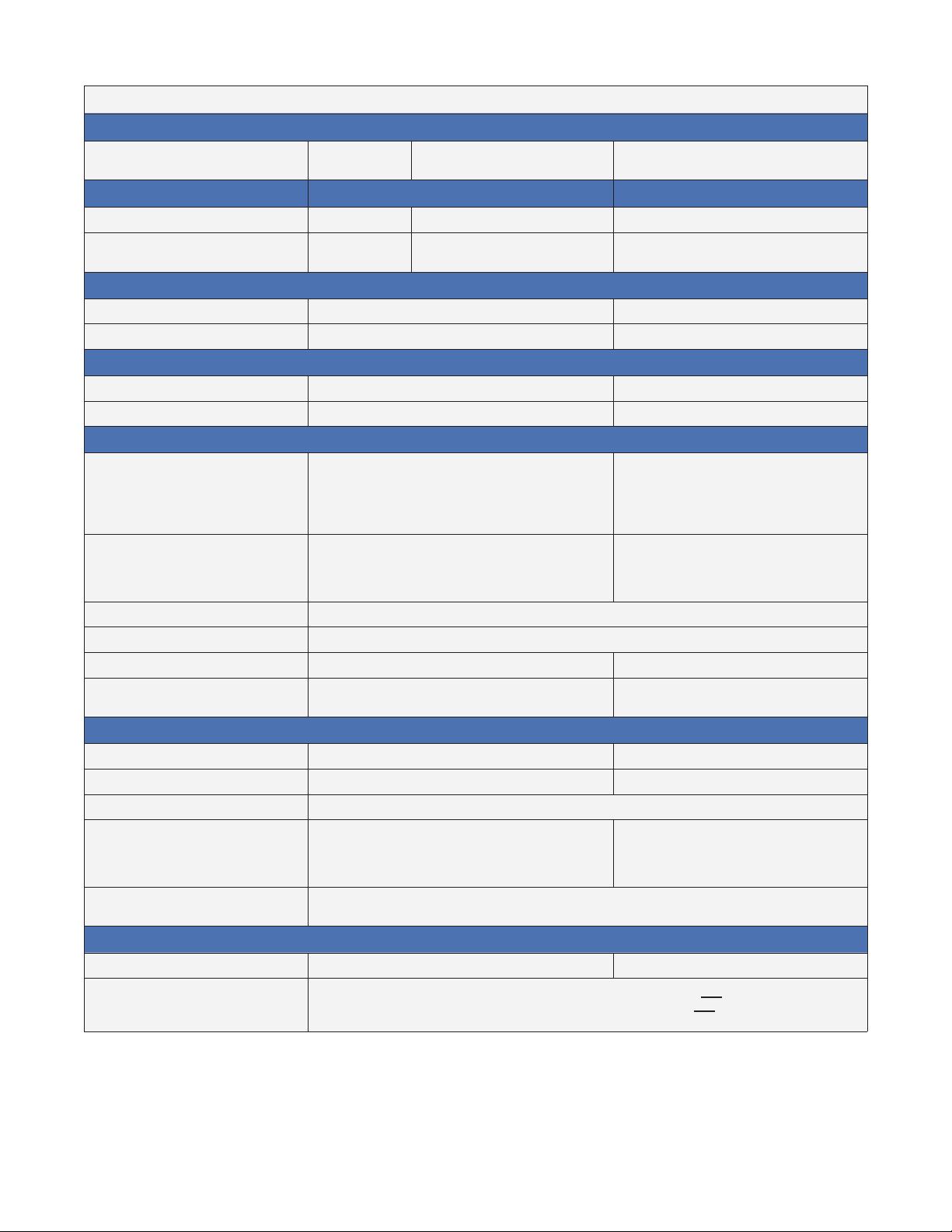
3.1 Specifications
T able A — Specications for Mid Capacity Power Systems
Model number
Model
CXPS-M
1200
23" Rack 19" Rack
Maximum Output Power 57.6 kW 57.6 kW 57.6 kW
Maximum Current 1200 A
Dimensions (with Kydex cover)
Metric (cm) 213.3 H x 66.0 W x 48.2 D 213.3 H x 48.2 W x 48.2 D
Imperial (in) 84 H x 23 W x 19 D 84 H x 19 W x 19 D
Weight (rack with 2 distribution modules and two rectier shelves)
Metric (kg) 227 approx 191 approx
Imperial (lb) 500 approx 425 approx
Input AC to 4.0/3.6 kW Rectier Shelves (per feed)
208-277 Vac, 1 PH/ 22-15A
48-4.0 kW Shelf
360-480 Vac, 3 PH – 3 wire + N + Protective
Earth (PE)/ 22-15A
208-240 Vac, 3 PH - 3 wire + PE/ 39-30A
CXPS-M
1200/600
1200 A primary
600 A secondary
CXPS-M
1200-19
1200 A
208-277 Vac, 1 PH/ 22-15A
24-3.6 kW Shelf
Frequency Range
Recommended Feeder Breaker
Single Phase:
Three Phase: 30 A, #10 AWG Wye connection 4W
208-277 Vac, 1 PH/ 17-13A
360-480 Vac, 3 PH – 3 wire + N + PE/ 17-13A
208-240 Vac, 3 PH - 3 wire + PE/ 30-26A
45 ~ 65 Hz, (±0.5 Hz)
6x 30 A, #10 AWG per rectier shelf 5x 30 A, #10 AWG per rectier shelf
50 A, #6 AWG Delta connection 3W
208-277 Vac, 1 PH/ 17-13A
N/A
Input AC to 1.2 /2.0 kW Rectier Shelves (per feed)
48-2.0 kW Shelf 120-240 Vac, 1 PH/ 36-27A 120-240 Vac, 1 PH/ 12-9A
48-1.2 kW 19" Shelf* 120-240 Vac, 1 PH/ 12-15A 120-240 Vac, 1 PH/ 12-15A
Frequency range
Recommended Feeder Breaker
(2.0 kW Shelf)
Recommended Feeder Breaker
(1.2 kW Shelf)
1x 120 or 240 Vac, 50 A, #6 AWG (three
module feed)
1x 120 or 240 Vac, 30 A, #10 AWG (two
module feed)
120 Vac, 15A, #14 AWG (per individual feed of two rectiers)
240 Vac, 20A, #12 AWG (per individual feed of two rectiers)
45 ~ 65 Hz, (±0.5 Hz)
4x 120 or 240 Vac, 15A, #14AWG (per
rectier shelf)
Distribution Modules
No. of Modules/Bay Max 4 Max 2
2 banks of 12 plug-in bullet positions OR
Options per Module
1 bank of 12 plug-in bullet positions/1 bank of 3 positions TPL fuses combination
*The 19" shelf can be mounted in a 23" shelf with additional hardware.
2 banks of 3 positions of TPL fuses OR
9400004-J0 Rev B
11
Page 14

3.2 Cordex 4kW Rectifier Shelves
Each bay can contain up to five Cordex shelves that hold up to six individual rectifier modules.
3.2.1 AC Termination Wiring
The individual Cordex rectifier shelves are wired to the customer-provided AC termination panel. The AC input is
routed through a 1" knockout for direct connection to the rectifier shelf with appropriately sized wire according to
the local electrical codes.
Each shelf requires two AC input circuits. The required input voltage varies depends on the rectifier shelf option
chosen at the time of ordering—see Table A for details.
3.2.2 Cordex Rectifier Modules (Purchased Separately)
The rectifier modules are "hot swappable" allowing for quick replacement and easy maintenance of the system.
(They can be inserted or removed from the shelf without removing AC power or shutting down the entire system.)
See the Cordex rectifier shelf manual included with the system documentation package for detailed information.
The CXC controller provides central control of the rectifiers’ output level, load sharing, temperature compensation
and alarm reports. A CAN bus cable is wired or daisy-chained to each rectifier shelf for communication with the
Alpha CXC System Controller.
3.2.3 Rectifier Alarms and LEDs
Rectifier status, such as Mains OK, Minor and Major alarms, display on the rectifier front panel.
• When a Rectifier Major alarm is present, the module has shut down due to a critical fault.
• A Rectifier Minor alarm indicates the module has a noncritical alarm, however, it has not shut down.
See the Cordex rectifier manual included with the system documentation package for detailed information.
3.3 Cordex 2kW Rectifier Shelves
Each 2kw Cordex shelf holds up to five individual
rectifier modules.
See the shelf manual that ships with your system (P/N
030-807-J0) for rectifier and shelf details.
3.4 Cordex 1.2kW Rectifier Shelves
Cordex CXRF-HP 48-1.2kW 1RU shelf holds up to five
individual rectifier modules.
See the shelf manual that ships with your system (P/N
030-834-J0) for rectifier and shelf details.
12
9400004-J0 Rev B
Page 15

3.5 Cordex Converter Shelves (dual voltage systems)
Converter shelves are part of a dual voltage system. Depending on the required load voltage, the converters are
one of:
• 24V to 48VDC, 2 kW output per module (24-48V
5-Mod 23" shelf part number: 030-900-20)
• 48VDC to 24V, 2 kW output per module (48-24V
5-Mod 23" shelf part number: 030-900-20)
Figure 2 — CXDF 24-48/2kW converter module
9400004-J0 Rev B
13
Page 16
3.5.1 DC Charge Buses - Single Voltage
Each rectifier bay has two vertical charge bars—one that connects all the return terminals and one that connects
all the "hot" terminals of the rectifier shelves to the distribution modules (Figure 3). These bus bars are rated to
120 0A.
Battery returns can be connected to the top of the return bus bars. Optional external battery termination bus bars
are available to increase the number of terminations available (see "3.7 Battery Terminations" on page 19).
Batt (return)
Batt ("hot")
14
Relay Rack: 030-683-20
7' x 23" Zone 4
Figure 3 — Rear view showing DC charge buses (covers removed)
9400004-J0 Rev B
Page 17

3.5.2 DC Charge Buses - Dual Voltage
Dual voltage systems have three vertical charge bars:
• One connecting all of the return terminals
• One busbar connecting all the "hot" terminals of the rectifier shelves and the input to the converter shelf–rat-
ed for the maximum 1200A current.
• The third bus bar delivers secondary voltage from the converters to the load–rated to 600A.
Primary
voltage bus
Common
return bus
Secondary
voltage bus
9400004-J0 Rev B
Figure 4 — 1200A dual voltage system
15
Page 18
3.6 Distribution and T ermination
A 23" rack mounted system, is available with single 1200A output or 1200 A primary/ 600 A secondary (dual voltage with a common return). A 19" rack mounted system, is only available with a single 1200A output.
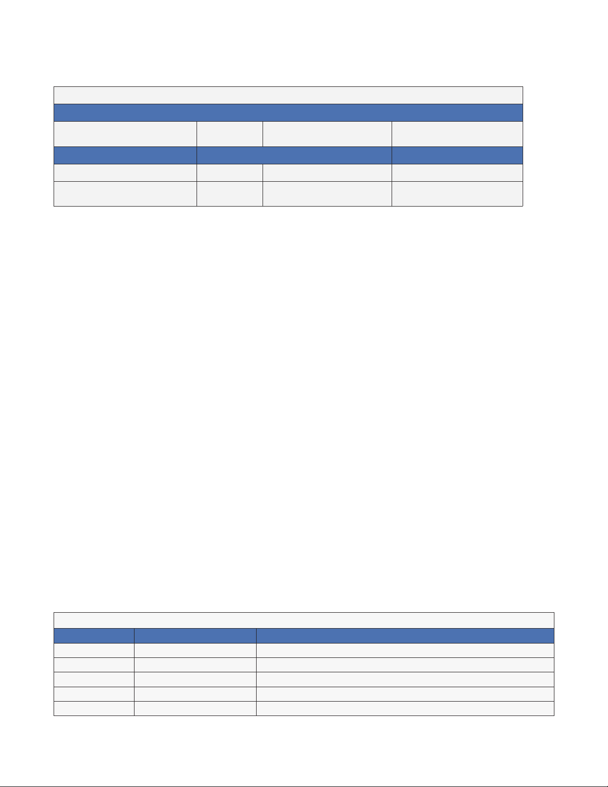
Table B — Mid Capacity Power Systems Output Congurations
Model number
Model
CXPS-M
1200
23" Rack 19" Rack
Maximum Output Power 57.6 kW 57.6 kW 57.6 kW
Maximum Current 1200 A
The fuse/circuit breaker distribution modules feature high capacity, modularity, and simplified installation. These
features provide effective secondary load distribution and protection for multiple DC feeds up to 600 amps.
3.6.1 Single Voltage Distribution
Each bay can have up to four distribution modules with a total current
capacity of 1200A. Table C lists component options across all four distribution modules.
Each module can contain one of the following configurations:
• 2 banks of 12 plug-in AM breakers/ TPS fuse holders
• 2 banks of 3 TPL fuses
• 1 bank of 12 plug-in AM breakers/ TPS fuse holders and 1 bank of
TPL fuses
Figure 5 shows a combination of two modules with two banks of circuit
breakers and two modules with one bank of TPL fuses and one bank of
plug-in breakers.
CXPS-M
1200/600
1200 A primary
600 A secondary
CXPS-M
1200
1200 A
16
Figure 5 — DC distribution modules
Table C — Modular distribution components and termination
Component Type Description/Connection
Fuses GMT: Up to 10 positions, up to 15A (max)
TPL, high capacity: Up to 6 positions, 800A max fuses
TPL, low capacity: Up to 24 positions, 300A max fuses
TLS/TPS plug-in bullet: Up to 96 positions, 125A max fuses
9400004-J0 Rev B
Page 19
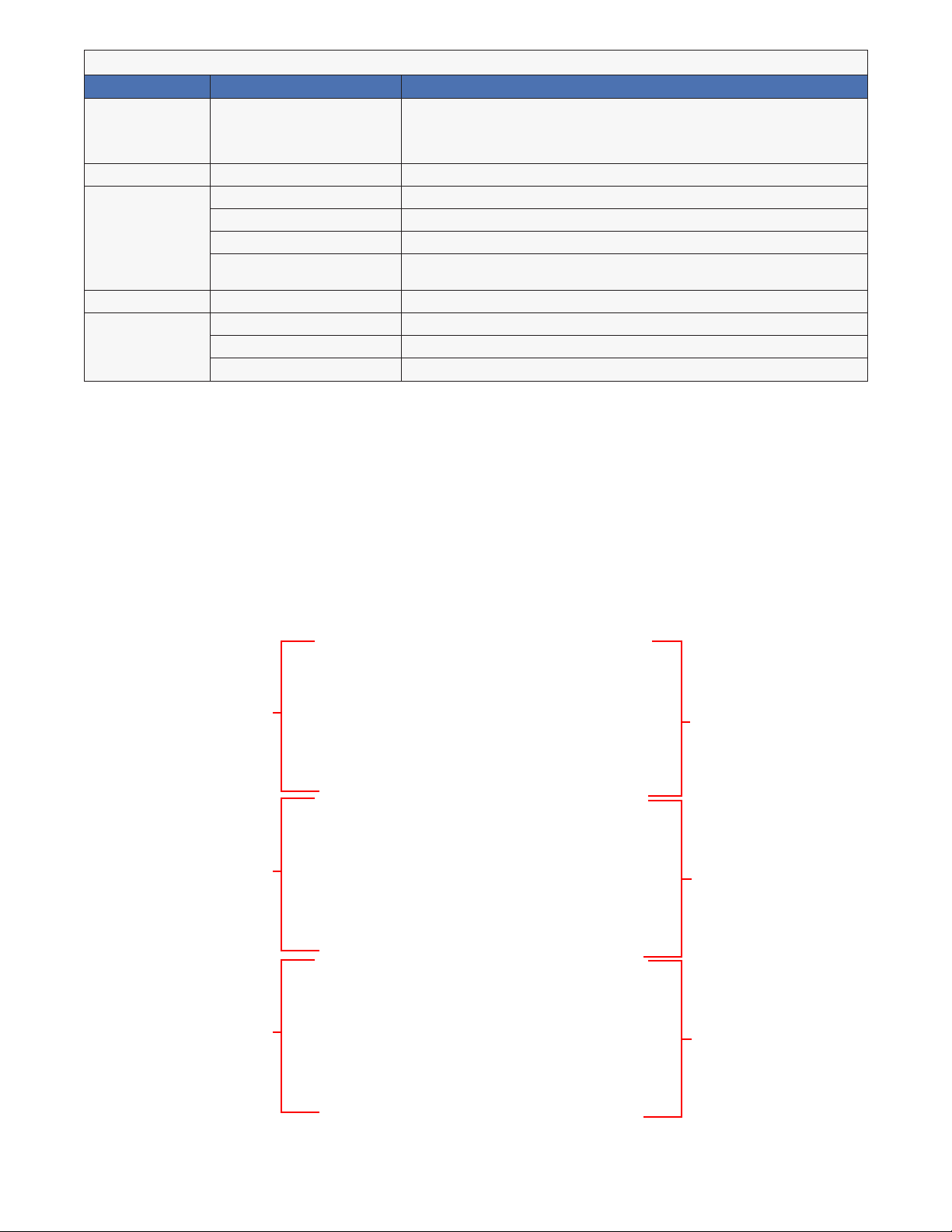
Table C — Modular distribution components and termination
Component Type Description/Connection
Breakers AM plug-in bullet: up to 96 positions
Output
termination
GMT Fuse: 0.34 to 2.5 mm
TPL fuse, high capacity: 2 hole 3/8" diameter on 1" centers, dual cable landing, 2x 750 MCM
TPL fuse, low capacity: 2 hole 3/8" diameter on 1" centers, 1x 350 MCM
TLS/TPS/AM breaker 1 pole and 2 pole: 1/4" diameter on 5/8" centers
1 pole, max 100A
2 pole, 125A to 150A
3 pole, 175A to 250A
2
(14 to 22AWG)
3 pole: 3/8" diameter on 1" centers
Module/Bank
Capacity
TLS/TPS/AM breaker 1200A/ 2x 600A per bank
TPL fuse 1200A/ 2x 600A
TPL fuse/ AM breaker 1200A/ 1x 600A plus 1x 600A
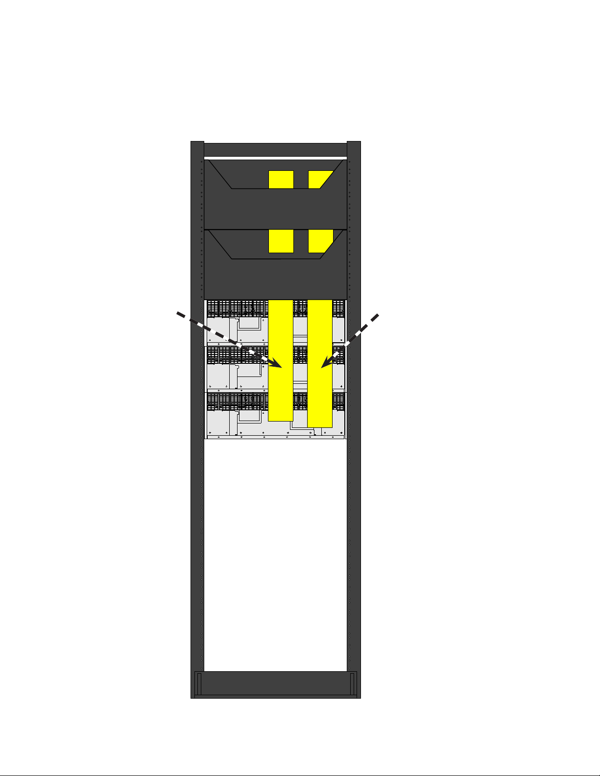
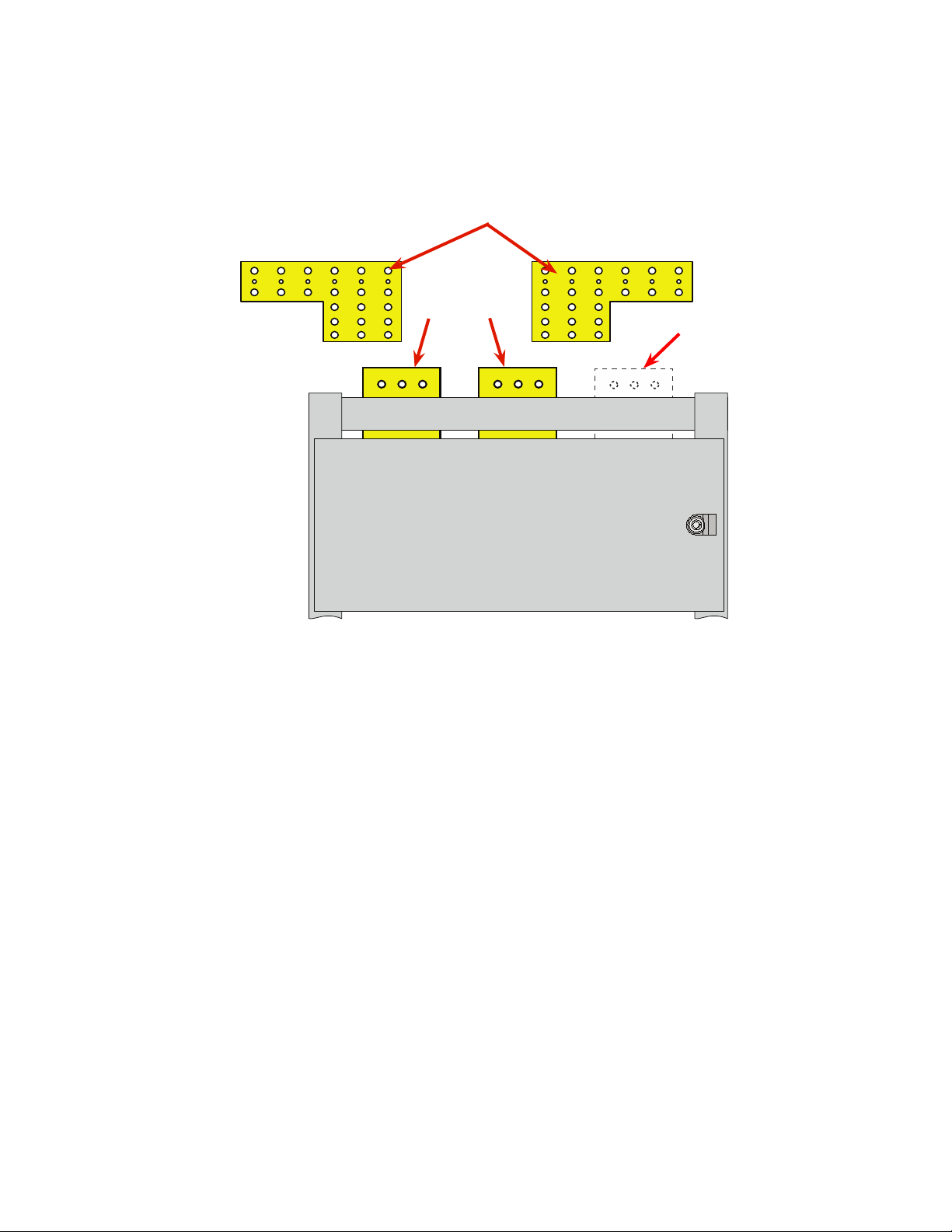
3.6.2 Dual Voltage Distribution
Each bay can have up to four distribution modules with a total current capacity of 1200A primary/ 600A secondary The top distribution module has primary distribution only and can contain any of the following configurations:
• 2 banks of 12 plug-in AM breakers/ TPS fuse holders
• 2 banks of 3 TPL fuses
• 1 bank of 12 plug-in AM breakers/ TPS fuse holders and 1 bank of TPL fuses
The remaining distribution modules with dual voltage distribution can have.
• 2 banks of 12 plug-in AM breakers/ TPS fuse holders
• Primary bank of 3 TPL fuses and secondary bank of 12 plug-in AM breakers/ TPS fuse holders
Primary distribution
Primary distribution
Primary distribution
Primary distribution
9400004-J0 Rev B
Secondary distribution
Secondary distribution
Figure 6 — Dual Voltage distribution modules
17
Page 20
3.6.3 Safety Features
Insulating shield
Each distribution bay has an insulating shield to the front of the bus bars. This shield prevents casual touching of
the bus bars with cable lugs and tools while working inside the distribution module. It also maintains separation
between the cables and the bus bars.
Insulation shield
Figure 7 — Distribution module installation shield
Circuit Breaker Guard
The pivoting circuit breaker guard, with a circuit designation strip, prevents accidental tripping of a breaker
and provides a secondary retention method.
Circuit breaker
guard
18
9400004-J0 Rev B
Page 21
3.7 Battery Terminations
The vertical DC busbars terminate in the top distribution module. Each busbar has 3 battery connection points (6
connections if made both front and back)—3/8" on 1" centers.
Optional extensions, available in kit #0380060-001, can be attached to the "hot" primary and battery return
busbars to provide more connection points (either 3/8" on 1" centers or 1/2" on 1 3/4" centers). Refer to kit
#0380060-001 for installation instructions.
Optional extensions
"hot"
primary
Return
Extensions are not available
for secondary voltage bus-
bars (dual voltage option)
Figure 8 — Battery termination (front view)
9400004-J0 Rev B
19
Page 22

3.7.1 Remote Battery Return Bar Kit (Optional)
A remote battery return bar is required to facilitate termination of a high quantity of large cables. The kit mounts
to a customer supplied auxiliary frame (2 " x 9/16"). IT is required if the TPL fuseholders are ordered and is suggested for systems with 4 distribution modules.
Lug Spacing
See Figure 9 for exact dimensions. For
two bars, the number of connections
are:
Small: 72 sets 1/4" on 5/8" ctrs
Large: 24 sets 3/8" on 1" ctrs or
24 sets 1/2" on 1 ¾" ctrs
1.28
0.27
0.63
0.63
0.27
0.56
0.44
1.28
1.75
1.06
2.00
20
Figure 9 — Remote battery return bar: customer connections (single bar shown)
9400004-J0 Rev B
Page 23

3.8 Distribution Shunts
Each TPL fuse or breaker bank is connected to the distribution bus through an 800 A / 25 mV shunt. See
Figure 10 and F igur e 11.
The individual shunt currents can be viewed on the CXC to monitor load/ battery balance. If the system has
more than four shunts, then installation of the shunt multiplexer panel option is required to increase the number
of observable shunt currents at the CXC from 4 to 16. Shunts and TPL fuses may be used for battery protection
(programming required).
Minor alarms are triggered in the controller to warn when shunt load exceeds 80% of rating.
Figure 10 — TPL shunts
Figure 11 — Breaker bank shunt (one per bank)
3.8.1 Shunt Multiplexer Panel
The Cordex controller (CXC) can monitor up to four current input channels, such as load currents and battery
charge currents. When the number of current inputs is more than four, an optional shunt multiplexer panel monitors the individual branch load currents within the distribution modules of the individual bay and sends the current
measurements to the CXC for data logging and display.
9400004-J0 Rev B
Figure 12 — Shunt mux panel mounted on the inside door of the top distribution module
21
Page 24

3.9 Low Voltage Load Disconnect
NOTE:
LVLDs are not installed in secondary voltage distribution banks.
The Low Voltage Load Disconnect (LVLD or LVD) feature controls a high
capacity contactor that disconnects the load during extremely low voltage conditions. The system loads are automatically reconnected once
AC is restored and battery voltage has risen above a preset value.
The parameters for LVD activation and control are set in the
Configure Controls
"Controls" in the controller software manual.
Each TPL fuse circuit in a given distribution bay, can have its own LVD.
Figure 13 shows the LVDs in a distribution module with two banks of TPL
fuses.
An LVD is also an option for a bank of breakers in a distribution module.
LVDs can also be configured as Low Voltage Battery Disconnects
(LVBD) and the associated breakers and fuses used for battery protection.
menu in the CXC controller. Refer to the section titled
Controls >
Figure 13 — LVD circuits
LVD Override
Activation of all LVDs, by the controller, is through Relay 1 (LVD 1).
To manually override the LVDs, position the LVD Override switch to OVERRIDE. This switch is mounted inside the
door of the distribution module with the controller—see Figure 14.
NOTE:
Setting the LVD Override switch to OVERRIDE generates an alarm on the CXC. See the
"Digital Alarms" section under "Congure Alarms" in the controller software manual.
22
9400004-J0 Rev B
Page 25

3.10 Distribution Panel Alarms
Fuse and breaker alarms occur when one or more fuse or breaker has opened.
Breaker alarms are paralleled from each breaker bank to a single alarm which is displayed on the inside panel of
the distribution module. The TPL fuse fail alarms, also paralleled, display as a single alarm.
Each breaker/fuse panel is equipped with one alarm which is wired to the system controller.
LVD Control Status LEDs
Green LED = OK to return to AUTO,
Supervisory LVD control is ON
Yellow LED = OVERRIDE
Yellow & Green
OFF together
= Contactor either open-circuit or
not installed
LVD #1
LVD #4
LVD Override Switch
Switch middle position = AUTO
Switch up position = OVERRIDE
CB/Fuse Alarm LEDs
#1 Left Bank Alarm
#2 Right Bank Alarm
#3 Secondary Voltage Alarm
LVD#1
#3
#2
#1
LVD #2
LVD #3
LVD#2
#3
#2
#1
LVD#3
LVD #5
LVD #6
Distribution
Module with
Controller
Shunt Multiplexer
Reset Button
9400004-J0 Rev B
LVD#4
LVD#5
LVD#6
Figure 14 — CB/fuse alarm LEDs and LVD control
Distribution
Module without Controller
23
Page 26

3.11 External Low Voltage Battery Disconnect (purchased separately)
The LVBD contactors, installed in the external battery disconnect panels, are placed in series with the batteries.
This product provides automatic disconnect of the system batteries after a prolonged power failure when the batteries have been fully discharged.
The batteries are automatically reconnected once AC is restored. Control is performed by the CXC and is triggered by the battery voltage.
3.12 Cordex System Controller
A Cordex system controller (CXCP), mounted in one of the distribution modules, provides easy access to controls
and display status. The CXCP features include the following:
• Direct communication with the Cordex rectifiers
• Battery temperature compensation charging
• Battery performance diagnostics
• Local and remote communications
• User definable alarms— a user can configure specific alarms through a programmable algorithm.
• Daily logging of power system events and system statistics
• Lithium battery backup to retain time and date settings if power is lost
See the CXC Software Manual, shipped with your order, for detailed information.
24
LEDs
Reset
button
Serial port
Figure 15 — CXCP controller mounted in a distribution module
9400004-J0 Rev B
Page 27

3.12.1 Control Cards
The control cards are mounted inside the door of the controller distribution module (Figure 16).
The CXCP can accommodate up to eight digital input channels. These channels can monitor digital alarm/control
signals from rectifiers, converters and other types of equipment. Some of these channels are pre-assigned to
monitor specific signals. See the Software manual for more information.
Each CXCP contains eight standard and eight optional Form C alarm output relays to extend alarms and control
external apparatus. Each internally generated alarm or control signal may be mapped to any one of the 16 relays,
or, several signals may be mapped to just one relay or none at all.
Refer to the detailed as-built schematic that ships in your documentation package.
I/O and Alarm
Interface
board
Cordex
Controller
board
Relays
Figure 16 — Control cards
Digital Inputs
LCD
Display
board
9400004-J0 Rev B
25
Page 28

3.12.2 Front Panel LEDs
Three LEDs are located on the front panel: one green, one yellow, and one red. These LEDs are used to display
the alarm status of the power system, controller progress and status during startup, and file transfers.
Alarm conditions
Only one LED light is illuminated at a time during alarm conditions. Each LED light corresponds to a specific
alarm. A built-in audio speaker sounds an intermittent tone during active alarms.
Illuminated LED Alarm
Green OK, no alarms
Yellow Minor alarm, no major alarms
Red Major alarm
Progress and status indication
The LED lights are also used in the following situations:
• Base unit validation—all three LEDs illuminate
• File transfer—red LED illuminates
3.12.3 Front Panel Reset Button
Use the controller LCD to select the RESET menu item before pressing the reset button. Refer to the software
manual for details.
Pressing the reset button, on the front panel, restarts the CXC microprocessor. It takes approximately 15 seconds
before the display reappears after pressing the reset button (Figure 15).
3.12.4 Network Connection and Remote Communications
The Cordex system can be set up, monitored, and tested via an Ethernet 10/100 Base-T serial data connection.
The controller includes a web server that provides easy set up and monitoring over an Internet connection to a
web browser.
Craft port
Local access to the CXC is possible through a front panel RS-232 serial port (Figure 15), using a null modem
cable. The communication protocol supports a web interface (Microsoft® Internet Explorer 6 or greater). The
remote screen display is an enhanced version of the CXC front panel display.
Ethernet port
An Ethernet port is located inside the front panel.
This port is designed to connect the controller to
a user supplied TCP/IP network. Use a standard
RJ-45 jack with a standard network cable.
The Ethernet port can be used for local access,
for example to a laptop computer. Use a standard
network crossover cable for the connection.
Internal CAN Bus
A CAN bus is used to transmit all alarm and control functions between the controller, shunt mux
and the rectifier shelves.
A single CAN Serial port, for communications with
other distribution modules is located inside the
front panel next to the Ethernet port.
Ethernet
port
CAN
port
26
9400004-J0 Rev B
Page 29

4. Pre-Installation Preparation
4.1 Site Selection
NOTE:
This power system is suitable for installation in Network Telecommunication facilities
and locations where the NEC applies.
The power system must be mounted in a clean and dry environment.
Consider both the floor loading and the physical space required for a single bay CXPS power system and the
batteries:
• Dimensions for one bay (refer to drawing #0250005-06):
x mm.........2133H x 660W x 482D
x Inches....84H x 26W x 19D
• Avoid areas that may be subjected to hot air exhaust from nearby equipment.
• Provide adequate space for safe and proper circulation of installation and maintenance personnel:
x Top: clearance required for cables
x Rear: 3ft (1m) during installation; after installation. a bay can be moved closer to a wall provided
~12" clearance is maintained for ventilation
x Front: 3ft (1m)
x Sides: If the optional battery bus bars are installed, allow ~6in (15cm) additional space on the live
side of the power system (Figure 17). For a dual voltage system additional space is required on
both sides to accommodate both load voltage bus bars.
9400004-J0 Rev B
Figure 17 — Battery terminations shown with protective covers
27
Page 30

4.1.1 Floor Plan Layout
Sufficient free space must be provided at the front and rear of the power system to meet the cooling requirements
of the rectifiers in the power system and to allow easy access to the power system components.
Consider the following before selecting a location for the CXPS power system
• Structure of building able to support the additional weight
• Enough space to meet requirements for access
• Enough space to meet cooling requirements of the rectifiers
• Adequate space to do the install
• Route that equipment will take through the building to reach the site
• Check and record distances to load
• Check and record distances to AC power source
• Check and record distances to batteries/DC power source
• Understand the full load on the DC system
• Window for working hours and other similar restrictions
• How much and what kind of prep work can be done in advance
x Reinforce floors
x Install distribution panels
x Install cable racks
x Run wiring
x Minimize cable lengths (cost)
x Minimize cable flow and congestion
28
9400004-J0 Rev B
Page 31

4.1.2 Installation component requirements
Supplied
• Internal cabling
Not Supplied
• Concrete and metal grating mounting hardware
• AC electrical conduit, cable and fittings
• External DC conduit, cable and fittings
• Auxiliary frame (2" x 9/16") for external battery return busbar kit
4.2 Tools and Test Equipment
Insulated tools are essential for a DC power system installation. Use the following list as a guide:
• Electric drill with hammer action
• Digital voltmeter equipped with test leads
• Lap top computer with Internet Explorer 8 for communication with the Cordex Controller (not required for
initial installation and test)
• Various crimping tools and dies, to match lugs used in installation
• Torque wrench:1/4" drive, 0-150 in-lb for battery post connections
• Torque wrench: 3/8" drive, 0-100 ft-lb for system connections
• Insulating canvases as required (2' x 2', 1' x 1', 3' x 3', etc.)
• Cutters and wire strippers (#14 to #22 AWG) [2.5 – 34 mm2]
• Insulated hand tools listed below:
Combination wrenches
Ratchet and socket set
Various screwdrivers
Electricians knife
Fine tipped slot screwdriver (“tweaker”)
Cable cutters
4.3 Floor Loading
4.3.1 Concrete floors (for reference only)
Concrete floor installation requiring seismic compliance requires approval by the appropriate engineering discipline, i.e., civil, structural etc. The thickness of the concrete should be evaluated to ensure that its weight carrying
capabilities meet the requirements.
Check the building floor plans for the presence of pipes, conduits, beams or any other obstructions in the concrete slab that could interfere with the drilling.
Figure 18 shows the dimensions and bolt locations of a single bay. An anchoring kit is provided with hardware for
the slots
9400004-J0 Rev B
29
Page 32

4.4 Unpacking the Equipment
Product is shipped upright bolted to a pallet or horizontally in a wooden crate. Packaging assemblies and methods are tested to International Safe Transit Association standards.
Rectifiers and batteries are shipped on individual pallets.
Check For Damage
Prior to unpacking the batteries, power system or components, perform a visual inspection and note any damage. Unpack the equipment and inspect the exterior for damage. If any damage is observed contact the carrier
immediately.
Continue the inspection for any internal damage. In the unlikely event of internal damage, please inform the carrier and contact Alpha Technologies for advice on the consequence of any damage.
General Receipt of Shipment
Consult the packing slip and power plant bill of materials to verify that you have everything on your order.
The inventory included with your shipment is dependant upon the options you have ordered. The options are
clearly marked on the labels on the shipping containers.
Rectifiers and Converters (Purchased Separately)
Consult the packing slip to verify that you have the correct number of rectifiers per your order.
Miscellaneous Small Parts
Review the packing slip and bill of material to determine the part number of the “configuration kits” included with
your plant;
Review the bill of materials (per the configuration kits that you determined above) to verify all the small parts are
included.
The part number is stamped on each piece of copper bar. Inspect these and match the items with your bill of
materials.
External Return Bus Bar (Purchased Separately)
Consult the packing slip to verify that you have the correct parts.
Battery Disconnect (Purchased Separately)
Consult the packing slip to verify that you have the correct number of battery disconnect units if applicable.
Batteries (Purchased Separately)
Verify that you have the correct number of batteries if applicable. Refer to the packing list.
Verify that you have all the necessary parts per your order for proper assembly.
Call Alpha Technologies if you have any questions before you proceed: 1-888-462-7487
30
9400004-J0 Rev B
Page 33

5. Installation
The power system must be mounted in a clean and dry environment. Provide sufficient free space at the front
and rear of the power system to meet the cooling requirements of the rectifiers in the power system and to allow
easy access to the power system components.
5.1 Floor drilling for standard anchoring
The anchoring kit and procedures in this section are for a sesimic installation, but apply equally well to a nonseismic installation.
5.1.1 Drilling the holes for the anchor bolts
1. Use a rebar locator to plan for the anchor positions.
2. Refer to Figure 18 (drawing 0300047-06) to mark the four anchor hole positions for seismic anchoring.
The red dots show the preferred location for the anchor holes within the slots.
Locate bolts in
Ø0.938 TYP
2.312 TYP
slots as shown for
greatest stability.
Ø0.75 TYP
13.0
9.6
18.1
23.5
Figure 18 — Template for anchoring bolts
9400004-J0 Rev B
31
Page 34

5.1.2 Setting the Anchors
First, review manufacturer's instructions before setting the anchor.
1. Drop the anchor into the drilled hole.
2. Insert the anchor setting tool and hit it with a hammer to expand the anchor until the collar of the setting tool
rests against the shoulder of the anchor.
5.2 Placing and Securing the Bay
5.2.1 Securing the bay to the floor
NOTE:
It is extremely important that the frame be properly shimmed in order to prevent any
frame distortion.
1. Place the frame in position over the anchoring holes (and the isolation pad if applicable).
2. Install the anchoring hardware for each anchor FINGER TIGHT.
3. Check that the bay is level front-to-back and side-to-side.
4. Add shims as needed under one or two of the corners of the bay, placing the shims as close as possible to
the bolts. To place a shim, take just enough weight off the bay to slide the shim into place.
5. Allow the full weight of the bay to rest on the shims, and then check the level again.
6. Once the bay is level, tighten all bolts to the appropriate torque (see "Table F — Recommended torque
values" on page 38.
32
9400004-J0 Rev B
Page 35

5.3 Mounting the External Battery Return Bus Bar (Optional)
An external battery return bus bar kit (part number 7400250-001) is available to make the battery return connections for the loads and to serve as the common connecting points for the positive side of the bay and the batteries.
Each bar has a 2500A capacity.
1. Before joining ground bar components together, ensure that all contact surfaces on the busbars are clean
and coated with a thin coat of NO-OX-ID “A” compound (or approved equivalent).
2. Assemble and mount the kit on a customer supplied auxiliary framing superstructure away from the system.
6.00"
47.75"
9400004-J0 Rev B
Customer supplied auxiliary
frame (2 " x 9/16")
Figure 19 — External battery return bus bar kit (2 bars shown)
33
Page 36

5.4 Battery Installation
WARNING!
Follow battery manufacturer’s safety recommendations when working around battery
systems. Review the safety instructions provided in "1.5 Battery Safety" on page 8.
Batteries should be located in a temperature-controlled environment. The temperature should be regulated at
approx. 25°C (77°F). Significantly lower temperatures reduce performance and higher temperatures decrease life
expectancy.
5.4.1 Installation of Batteries in the Bay
The CXPS-M has an option for installing batteries in the bay. The battery shelves are pre-wired so the procedure
for installing batteries is quite simple:
1. Remove the guard rail.
2. Place the batteries in the shelf and connect the labelled cables to the batteries.
3. Replace the guard rail.
Pre-wired battery cables
34
Figure 20 — Battery shelf in the bay
9400004-J0 Rev B
Page 37

5.4.2 Installation of External Batteries
This information is provided as a guideline and is not meant to imply that batteries are part of this power system.
Verify that all battery breakers, DC circuit breakers, and fuses on the distribution panels are either in the OFF
position or removed.
Before assembly, clean cells (where applicable) as per the battery manufacturer's recommendations. First
neutralize any acid with a baking soda and water solution. Then wipe the cells with clean water. Use a corrosioninhibiting agent such as NO-OX or NCP-2 on all battery terminal connections.
1. Assemble battery rack (if required) and the cells or mono-blocks as per the installation instructions supplied
with the batteries.
2. Ensure that the battery output cabling will reach the [+] and [–] terminals of the series battery string and that
the batteries are oriented correctly for easy installation of the inter-unit “series” connectors.
3. Remove any no-oxide “A” grease from battery terminals.
4. Burnish terminal posts with a non-metallic brush, polishing pad or 3M-type scotch pad.
5. Apply a light coating of no-oxide “A” grease to the terminal posts.
6. If lead plated inter-unit connectors are used, they should also be burnished and no-oxide “A” grease applied
as above. Install the inter-unit connectors.
7. After all battery connections are completed, torque per battery specifications (typically 100 in-lbs).
8. See system startup procedure before connecting batteries online.
5.4.3 Temperature Probe for Monitoring Battery Temperature
1. Connect CXC temperature probes from CXC to battery termination post negative, if applicable. Pick a good
location at mid-height on one or more battery string that will provide a good average temperature reading;
i.e., away from heating or cooling sources.
Temp.
probe
9400004-J0 Rev B
Figure 21 — Temperature probe
35
Page 38

After assembly, number the batteries and take “as received” readings, including specific gravity, cell voltage,
and temperature. Designate one cell as the pilot cell. This is usually the cell with either the lowest specific gravity or voltage. Refer to the manufacturer's literature for guidelines. See the following table for typical maintenance
report:
Company: _____________________________________________________ Date: _____________________
Address: _________________________________________________________________________________
Battery location and/or number:_______________________________________________________________
No. of cells: _______________ Type: __________________________ Date new: _______________________
Date installed: __________________ Float voltage: ____________________ Ambient temp.: ______________
Table D — Typical VRLA battery maintenance report
Cell # Serial # Voltage Specic Ohms Mhos Observations
Remarks and recommendations: ________________________________________________________
__________________________________________________________________________________
__________________________________________________________________________________
Readings taken by: _________________________________________
36
9400004-J0 Rev B
Page 39

6. Installation - AC, DC and Grounding Cables
This section provides cabling details and notes on cable sizing for DC applications with respect to the Alpha
CXPS-M Power System.
• Only qualified personnel should install and connect the power components within the Alpha power system.
• All wiring must be in accordance with applicable electrical codes.
• A low voltage disconnect (LVBD) should be provided with the battery system.
• Electrical codes require that conductors carrying AC current be installed separately from conductors carry-
ing DC current and signals.
6.1 Installation Notes
6.1.1 Installer Responsibility
The system arrives pre-wired, and the installer is responsible for connecting the following:
• Utility input to the system
• Battery strings
• System to the load
• Chassis and battery return to the reference ground
6.1.2 Calculating Output Wire Size Requirements
Although DC power wiring and cabling in telecommunication applications tend to exceed electrical code requirements, mostly due to the voltage drop requirements, all
applicable electrical code(s) take precedence over the guidelines and procedures in the
present chapter, wherever applicable.
Wire size is calculated by first determining the appropriate maximum voltage drop requirement. Use the formula
below to calculate the circular mil area (CMA) wire size requirement. Determine the size and number of conductors required to satisfy the CMA requirement.
CMA = (A x LF x K) / AVD
A = Ultimate drain in amps
LF = Conductor loop feet
K = 11.1 constant factor for commercial (TW type) copper wire
AVD = Allowable voltage drop
Check again that the ampacity rating of the cable meets the requirement for the installation application. Consult
local electrical codes (NEC, CEC, etc.) for guidelines. If required, increase the size of the cable to meet the code.
Refer to Table E for cable size equivalents.
9400004-J0 Rev B
37
Page 40

Table E — Cable size equivalents (AWG to Metric)
Cable size (see notes 1
and 2)
20 AWG 1020 0.519 1
18 AWG 1624 0.8232 1
16 AWG 2583 1.309 1.5
14 AWG 4107 2.081 2.5
12 AWG 6530 3.309 4
10 AWG 10380 5.261 6
8 AWG 16510 8.368 10
6 AWG 26250 13.30 16
4 AWG 41740 21.15 25
2 AWG 66370 33.63 35
0 AWG (or 1/0) 105600 53.48 50 or 70
00 AWG (or 2/0) 133100 67.42 70
0000 AWG (or 4/0) 211600 107.2 120
313 MCM (or kcmil) 313600 159 150 or 185
350 MCM (or kcmil) 350000 177.36 185
373 MCM (or kcmil) 373700 189 185 or 240
500 MCM (or kcmil) 500000 253.36 300
535 MCM (or kcmil) 535300 271 300
750 MCM (or kcmil) 750000 380.00 400
777 MCM (or kcmil) 777700 394 400
t
Circular mils Square millimeters Equivalent metric cable
6.1.3 Recommended Torque Values
Recommended torque values for connection to the power system:
x Clear hole connections (nut and bolt)
x PEM studs
x PEM threaded inserts
x Thread formed connections (in copper bus bar)
Table F — Recommended torque values
1/4" 8.8 ft-lbs
3/8" 32.5 ft-lbs
1/2" 73 ft-lbs
SAE Grade 5 rating is required for these torque values.
6.1.4 Cabling Layout
The cabling at the time of installation is straightforward.
x The AC cables for the rectifiers connect to the shelves on both sides, and are brought down from
the top of the frame to the rectifier shelves.
x The battery cables and the external battery return bar (if equipped) connect to the bay at the top
rear.
x The load cables to the distribution modules enter the bay through the top.
x The load return cables connect to the distribution modules or an external battery return bar
x All signaling wires (for example, alarms from the CXC Controller) interfacing with the outside world
exit the frame through the top or through the conduit opening.
38
9400004-J0 Rev B
Page 41

6.2 AC Supply for the Rectifiers
To ease future access issues, connect the AC circuits to all rectifier shelves at the time of initial installation.
NOTE:
Verify NO rectiers are installed in the rectier shelves at this time.
6.2.1 Standard AC
Table A lists the types of rectifiers that can be installed in a CXPS-M system. Table A also provides the AC input
specifications.
Figure 22 shows the AC connections for one of the rectifier shelves. For other AC connection options (e.g. single
phase), refer to the rectifier shelf manual that ships with your system.
Terminate flex conduit at rectifier shelves—one connection each side.
AC wireway 1.313"
(33.4mm) for 1"
conduit
Figure 22 — Shelf AC connection (208Vac, 3 phase, 3-wire shown with rear cover removed)
9400004-J0 Rev B
39
Page 42

6.3 Connecting the Frame and Reference Grounds
CAUTION!
The grounding methods described in this section are generic. Follow local requirements
and electrical code.
NOTE:
This power system is suitable for installation as part of a Common Bonding Network
(CBN) and is intended to be used in a DC-C conguration (common DC return).
A true single point ground system means that everything is referenced to a single point that is tied to the external
earth ground system. In reality each component and external source is effectively bonded to a single point, which
is then effectively bonded to the facility or site external ground system.
6.3.1 Connecting the power plant battery return reference lead
1. Connect the isolated power system battery return bus (BRB) to the building master ground bus (MGB) or
floor ground bus (FGB) in larger buildings (Figure 23). This acts as a system reference and a low impedance
ground path for surges, transients, noise, etc. The MGB or FGB should have a direct low impedance path to
the building grounding system.
2. Size the cable between the power system and the MGB or FGB so that there is sufficient ampacity to clear
the largest fuse or breaker on the power system, excluding the battery protection fuse or circuit breaker—see
Table G on page 41. This is the minimum requirement for these high capacity plants. Other factors, including
length of cable and special grounding requirements of the load, must be factored in. The insulated cable
should be equipped with two-hole crimp type lugs and should not have any tight bends or kinks.
To site
ground
MGB or FGB
BRB
Frame
ground
CXPS power
system bay
Battery rack Battery rack
Optional external battery plant
40
Figure 23 — Frame and reference returns (front view)
9400004-J0 Rev B
Page 43

Table G — Typical Ground Reference Conductor Selection
System Ampacity Typical ground reference conductor size
< 30A #10
30-100A #6-2
100-400A 0000
400-800A 350 MCM
> 800A 750 MCM
6.3.2 Connecting the power plant frame ground
The power plant frame must also be connected to the MGB or FGB—see Figure 23. This is done for personnel
safety and to meet many telco-grounding requirements. Cable should be #6 AWG (16mm) for small to medium
size power plants and #2/0 for large plants (> 800A).
Frame ground
¼" on 5/8" centers
9400004-J0 Rev B
Figure 24 — Frame reference ground (top of bay)
41
Page 44

6.4 External Battery Return Bar Wiring (Optional)
Connect the external battery return bar(s) to the associated bay's battery return bus as shown in Figure 25.
NOTE:
The return side of TPL fuse holders must connect directly to the external return bus bar.
3x 750 MCM (reco-
External battery return bar
mended for 1200A
applications)
CXPS-M power
system bay
Figure 25 — Remote battery return bar wiring
42
9400004-J0 Rev B
Page 45

6.5 Battery Connections
Battery cables should be sized for a 0.25 V drop from battery to the power system at full load including anticipated growth. The cables should also meet ampacity requirements.
6.5.1 Battery Return Connections
Procedure:
1. Connect the battery return cables to an external battery return bus bar, if installed, (Figure 26) or to the return
bus bar termination on the bay:
External Battery Return Bus Bar (Figure 26) Battery Return Termination on the Bay (Figure 27)
• 24 sets of 1/2" holes on 1¾" centers
• 24 sets of 3/8" holes on 1" centers
• 72 sets of 1/4" holes on 3/8" centers
• 6 sets of 1/2" on 1 3/4" centers and/or
3/8" on 1" centers (12 if connected to both
sides of the bar)
See Table F
on page 38 for
recommended
torque values.
Figure 26 — External battery return bus bar (dual level shown)
6.5.2 Hot Voltage Battery Cables
CAUTION!
Do NOT make nal connection to battery live. Insulate and leave disconnected or remove the battery fuses. Switch battery contactors off (if used).
1. Connect "hot" primary voltage cables directly to the primary "hot" voltage bus bar (Figure 27).
2. For the dual voltage option, connect "hot" secondary voltage cables directly to the secondary "hot" voltage
bus bar (Figure 27).
Primary "hot"
Return
"hot" secondary (dual
voltage option)
9400004-J0 Rev B
Figure 27 — Battery terminations (front view)
43
Page 46

6.6 Connecting DC Load Cables to Breaker/Fuse Circuitry
Refer to guidelines supplied with the load equipment. Distribution cables are typically sized to provide a 0.5 V
loop drop at full load as well as meeting ampacity requirements of the protection fuse or circuit breaker.
6.6.1 Before You Begin:
1. Cut cables to length and terminate with a two-hole lug:
x TPL fuse connection—3/8" diameter on 1" center
x AM breaker— 1/4" diameter on 5/8" center
2. Identify each cable with a label that indicates its location within the distribution modules.
3. Remove the top Kydex cover.
6.6.2 Load Cables to Breakers
1. Route the load cables through the top distribution module.
2. Remove the protective "hot" terminal cover (Figure 29).
3. If using 2-pole or 3-pole breakers (Figure 28), remove the Insulating materials between adjacent breakers
connections.
44
Remove
insulating
material
Figure 28 — Preparation for 2-pole and 3-pole breakers
9400004-J0 Rev B
Page 47

Circuit breaker
guard
Protective "hot" termi-
nal cover
Cable tie bar
Figure 29 — Breaker distribution module before load cables are installed
4. Connect the load return cables to the return side of the each breaker position starting at the bottom(Figure
30). Alternatively, connect the load return cables to the external battery return bus bar (Figure 26).
5. Connect the primary voltage load cables to circuit breaker positions from the bottom up, in the bottom
distribution module.
6. For the dual voltage option, connect the secondary voltage load cables to circuit breaker positions from the
bottom up, in the bottom distribution module.
7. Tie cables to the cable tie bars at the back of the power system (Figure 29 shows the location).
8. Add additional circuits going from bottom to top tying in the additional layers on top of the previous layers.
9400004-J0 Rev B
Load (return) – Connect here
or connect to external return
bus bar, if installed.
Load ("hot") connections
Figure 30 — Breaker load cable and return connections
45
Page 48

6.7 Connecting Load Cables to TPL Circuitry
NOTE:
TPL fuses are installed in primary voltage banks only.
The TPL extensions shown in Figure 31 are installed with kit #0380059-001, which also includes covers for the
extensions.
High Capacity
Connect TPL fuse holders to the load and the external return bus bar with up to 2x 750 MCM wire.
Low Capacity
Connect TPL fuse holders to the load and the external return bus bar with up to 350 MCM wire.
46
Figure 31 — High capacity TPL fuse wiring (shown with 2x 750 MCM wire)
9400004-J0 Rev B
Page 49

6.8 Final installation steps
6.8.1 Tie Wraps
Neatly group cables with tie wraps as shown in Figure 32.
9400004-J0 Rev B
Figure 32 — Final load cable arrangement (shown with protective covers removed)
47
Page 50

6.8.3 Top Cover(s)
Cut between the holes
with side cutters to make a
large enough entryway for
the required cables. Figure
33 shows a small hole cut
in the cover.
Make a straight cut to the
back edge of the cover,
so the cover can be fitted
around the cables when
replacing it at the end of the
installation.
Reinstall the top cover.
Figure 33 — Top Kydex cover with cuts for cable entry
6.8.2 Installing the battery cable insulation covers
Insulation cover kits, #0380060-001 are included with the initial shipment of the equipment—two kits for each
bay.
STEP 1
1. Start from the rear left and wrap an insulating cover around the cables and bus bar (refer to Figure 34 and
Figure 35).
2. Secure with the plastic pins.
48
Figure 34 — Insulation cover (rear view)
9400004-J0 Rev B
Page 51

STEP 2
Repeat on the right busbar and cables.
Figure 35 — Insulation covers in place
STEP 3
Secure the covers to the top of the bay with the plastic screws as shown in Figure 36.
9400004-J0 Rev B
Figure 36 — Securing Insulation covers to bay
49
Page 52

6.9 External Alarm Wiring
If using the alarm outputs from the CXCP relays, route the signal cable as shown in Figure 37 ,exiting through the
knockout in the top distribution module. Refer to the controller software manual to set up the alarms.
Figure 37 — Route of external signal wiring
WARNING!
To prevent electrical hazards such as short circuits, ensure that the system is free of
debris such as metal lings, screws, etc., after the installation is complete.
50
9400004-J0 Rev B
Page 53

7. System Startup
Visually inspect the installation thoroughly. After completing the system installation and power system wiring, perform the following startup and test procedure to ensure proper operation:
7.1 Check System Connections
1. Make sure that the AC input power is switched off, the batteries are disconnected, and all the power modules
are removed from the shelf.
2. Triple-check the polarity of all connections.
7.2 Verify AC and Power the Rectifier Shelf
1. Install one power module.
2. Verify that the AC input voltage is correct and switch on the corresponding feeder breaker. The power
module OK LED will illuminate after a preset start delay.
7.3 Check Battery Polarity and Connect
1. Use a voltmeter to verify that the battery polarity is correct. Ensure that no cells or batteries are reversed.
2. Connect the batteries or switch on the battery circuits.
3. Install the remaining power modules.
4. In the adjustments menu of the CXC, set the float and equalize voltages to the levels specified by the battery
manufacturer.
7.4 Final Configuration and Test
1. Configure other system parameters as required—changing the low and high voltage AC and DC warning and
cutout limits, for example.
2. At this point there should be no alarms present. Investigate and correct any alarm issues.
3. Test the functionality of various alarms and controls as follows:
Alarm Test
Minor alarm
Major alarm To simulate a major alarm, shutdown two rectiers.
AC Fail alarm Turn off all AC breakers and run on batteries.
Supervisory Fail At the controller, tap the Home icon at the lower left of the “home” page and select
4. Perform a system load test using a resistive load box.
5. Turn off the AC input breaker to perform a full load test from DC power.
6. Enable the temperature compensation (temp comp) feature in the batteries menu. Program the settings for
slope and breakpoints (upper and lower) according to the specific batteries used.
To simulate a minor alarm, shutdown one rectier.
Reset from the pop-up menu.
9400004-J0 Rev B
51
Page 54

8. Test and Commissioning Overview
8.1 System
All Alpha power system components undergo thorough factory testing. All levels/alarms are set to predetermined
values as detailed in their individual component manuals except where custom levels are specified. Good installation practice is to check the operation of all features and alarms and to set the power system levels in accordance with the specific requirements of your system.
The individual system component manuals detail the methodology for testing and calibration of all components.
NOTE:
A Load Current High (minor) alarm will be triggered when the system amperage reaches
80% of the bay rating.
8.2 Battery
After installation of batteries it is usually necessary to “initial charge” the batteries to ensure proper operation
and to eliminate plate sulfation. Follow guidelines supplied with the battery and record initial charge readings; i.e.
specific gravity, cell voltage, charge current and temperature.
Battery warranty may be void if batteries are not initially charged following the manufacture's guidelines – with
proper records maintained.
Some VRLA batteries do not require initial charging, if placed on charge within 3-6 months of manufacture, check
with the manufacturer.
After the equalization period battery voltage should be reduced to the recommended float level.
Once the batteries have been initial charged it is suggested to perform a short duration high rate discharge test
on the batteries to verify the connections on the batteries and also to verify that there are no open or failed cells.
Cell voltages should be monitored during this process:
• Discharge for 15 minutes at the C/8 rate.
• Record cell voltages every 5 minutes.
• Check for overheating connections.
8.3 Documentation
Complete all necessary documentation; i.e., battery reports, DC wiring lists, AC distribution tables, floor plans,
etc. Tag wires, fill out identification strips, and identify circuit breakers.
52
9400004-J0 Rev B
Page 55

9. Maintenance
Although very little maintenance is required with Alpha systems, routine checks and adjustments are recommended to ensure optimum system performance. Qualified service personnel should do the repairs.
The following table lists a few maintenance procedures for this system. These procedures should be performed
at least once a year.
WARNING!
Use extreme care when working inside the unit while the system is energized. Do not
make contact with live components or parts.
Circuit cards, including RAM chips, can be damaged by static electricity. Always wear a
grounded wrist strap when handling or installing circuit cards.
Ensure redundant modules or batteries are used to eliminate the threat of service interruptions while performing maintenance on the system’s alarms and control settings.
Table H — Sample maintenance log
Procedure Date Completed
Clean ventilation openings.
Inspect all system connections. Re-torque if necessary.
Verify alarm/control settings.
Verify alarm relay operation.
9.1 Rectifiers
It is recommended that every five years MOV surge suppressors are replaced (especially in areas of high lightning activity).
See Cordex rectifier manual for general maintenance information.
9.2 Controller Lithium Battery Replacement
NOTE:
Replace the battery within 30 seconds to prevent loss of date and time.
A removable lithium battery is located near the back and to the right of the motherboard. The battery life is rated
up to three years, but replace earlier if the panel does not maintain date and time during power interruption.
WARNING!
Exercise extreme caution and do not touch any connected equipment.
To replace the lithium battery, shut down the CXC, remove the rear cover, and pull battery out carefully. Ensure
that the new battery is the same as the one being replaced.
9.3 Batteries
It is recommended that checks are made every six months for battery voltage, conductance, temperature, impedance, connections, etc.
See battery manufacturer's manual for general maintenance information.
9400004-J0 Rev B
53
Page 56

9.4 Adding Rectifier Shelves
The CAN bus provides a communication path between the controller and rectifiers. In a single bay, the CAN bus
cabling is daisy-chained from the shunt mux, if installed, to the bottom rectifier shelf. The cable is then daisychained from the bottom shelf, to higher shelves, in sequence. At the last shelf, termination is enabled—see
Figure 38.
CAN termination enabled
Figure 38 — CAN bus termination
CAN termination disabled
NOTE:
If your system has redundant rectiers, it is recommended to power off the left most
rectier in the top shelf of the existing bay during this procedure.
1. Remove the left most rectifier in the top shelf of the
existing bay. (Refer to the Rectifier Shelf manual for
the removal and re-insertion procedure.)
2. Flip the DIP switches from Termination Enabled to
Termination Disabled—see Figure 38.
3. Replace the rectifier.
4. Connect the CAN bus cable to the CAN OUT
connector of the top rectifier shelf of the expansion
bay.
54
Figure 39 — CAN OUT connection
9400004-J0 Rev B
Page 57

9.5 Spares
Description Part #
Interface board -48V / +24V 70 50132- 002
Interface board -24V / -48V 7050132-003
Interface board +24V / -48V 7050132- 004
Slam Latch 6470008
9400004-J0 Rev B
55
Page 58

10. Acronyms and Definitions
AC Alternating current
ANSI American National Standards Institute
AWG American Wire Gauge
BRB Battery return bus
BTU British thermal unit
CAN Controller area network
CEC Canadian Electrical Code
CSA Canadian Standards Association
CX Cordex™ series; e.g., CXC for Cordex System Controller
DC Direct current
DHCP
EIA Electronic Industries Alliance
EMC Electromagnetic compatibility
EMI Electromagnetic interference
ERM Electromagnetic Compatibility and Radio Spectrum Matters
ESD Electrostatic Discharge
FCC
GSM Group Speciale Mobile (global system for mobile communications)
HVSD High voltage shutdown
IEC International Electrotechnical Commission
IEEE Institute of Electrical and Electronics Engineers
IP Internet Protocol
LED Light emitting diode
LVD
MIL One thousandth of an inch; used in expressing wire cross sectional area
MOV
MTBF Mean time between failures
NC Normally closed
NEC
NO Normally open
OSHA Occupational Safety & Health Administration
OVP
RAM Random access memory
RU
SAE Society of Automotive Engineers
TCP/IP Transmission Control Protocol / Internet Protocol
THD Total harmonic distortion
UL Underwriters Laboratories
VRLA
Dynamic Host Conguration Protocol
Federal Communications Commission (for the USA)
Low voltage disconnect
Metal oxide varistor
National Electrical Code (for the USA)
Over voltage protection
Rack unit (1.75”)
Valve regulated lead acid
56
9400004-J0 Rev B
Page 59

11. Warranty
Alpha Technologies Ltd. warrants all equipment manufactured by it to be free from defects in parts and labor, for
a period of two years from the date of shipment from the factory. The warranty provides for repairing, replacing
or issuing credit (at Alpha’s discretion) for any equipment manufactured by it and returned by the customer to
the factory or other authorized location during the warranty period. There are limitations to this warranty coverage. The warranty does not provide to the customer or other parties any remedies other than the above. It does
not provide coverage for any loss of profits, loss of use, costs for removal or installation of defective equipment,
damages or consequential damages based upon equipment failure during or after the warranty period. No other
obligations are expressed or implied. Warranty also does not cover damage or equipment failure due to cause(s)
external to the unit including, but not limited to, environmental conditions, water damage, power surges or any
other external influence.
The customer is responsible for all shipping and handling charges. Where products are covered under warranty
Alpha will pay the cost of shipping the repaired or replacement unit back to the customer.
11.1 Battery Warranty
Note that battery warranty terms and conditions vary by battery and by intended use. The most common battery
warranty provided by Alpha is a two year full replacement warranty with a pro-rated warranty for the following
three years. Pro rated warranty provides a credit applicable toward the purchase of new batteries from Alpha. The
credit is calculated as the purchase price multiplied by the percentage of the battery life that was not available (in
months). Battery warranty coverage is lost where the battery charge is not maintained for 6 months. Contact your
Alpha sales representative or the Technical Support team at the above number to understand your entitlements
under Battery Warranty.
9400004-J0 Rev B
57
Page 60

CXDF 48-24/2kW
7'
40
35
0200042-012
TPL Distribution Module
e/w large cable landings
6x 600A TPL Fuse
TM
STATUS
RS 232
STATUS
RS 232
Cordex
CXC
Positions and shunts.
0200042-036
TPL Distribution Module
e/w small cable landings
6x 600A TPL Fuse
Positions, shunts and
STATUS
RS 232
Controller
KYDEX REAR
COVER VENTED
0901000-751
30
25
20
15
10
G N B
MARATHON
M12V105FT
0200042-035
TPL Distribution Module
e/w large cable landings
6x 600A TPL Fuse
STATUS
RS 232
Positions and shunts.
CXRF 48-4kW
Shelf: 030-801-20
Module: 010-623-20
CXRF 48-4kW
Shelf: 030-801-20
Module: 010-623-20
cordex
cordex
cordex
AC
CXDF 48-24/2kW
AC
CXDF 48-24/2kW
DC
DC
AL
AL
M
M
cordex
AC
CXDF 48-24/2kW
AC
CXDF 48-24/2kW
DC
DC
AL
AL
M
M
CXDF 48-24V Shelf: 030-840-20
CXDF48-24/2kW Module: 012-527-20
G N B
MARATHON
M12V105FT
G N B
MARATHON
M12V105FT
G N B
MARATHON
M12V105FT
BATTERY TRAY
0300061-001
TYPE: V1
5
0
DRAWN: AZ/RW
DATE:
CONFIG:
QUOTE:
4/5/2012
G N B
MARATHON
M12V105FT
G N B
MARATHON
M12V105FT
Relay Rack: 0300047-002
7' x 23" (1000lb) Zone 4
TITLE:
CHECKED:
APPROVED:
G N B
MARATHON
M12V105FT
G N B
MARATHON
M12V105FT
BATTERY TRAY
0300061-001
CXPS-M-1200/600, 3T-CB,-48/+24V,2R,1C,2BATT
ISSUED:
DWG NO:A SIZE
0540100-04
SHEET:
REV:
1OF 1
A
Page 61

Page 62

Page 63

Page 64

Page 65

Page 66

Page 67

Page 68

Alpha Technologies Ltd.
7700 Riverfront Gate
Burnaby, BC V5J 5M4
Canada
Tel: +1 604 436 5900
Fax: +1 604 436 1233
Toll Free: +1 800 667 8743
Alpha Technologies Inc.
3767 Alpha Way
Bellingham, WA 98226
United States
Tel: +1 360 647 2360
Fax: +1 360 671 4936
Alpha Industrial Power Inc.
1075 Satellite Blvd NW,
Suite 400
Suwanee, GA 30024
United States
Tel: +1 678 475 3995
Fax: +1 678 584 9259
Alpha Energy
1628 W Williams Drive
Phoenix, AZ 85027
United States
Tel: +1 602 997 1007
Fax: +1 623 249 7833
Alpha Technologies Europe Ltd.
Twyford House Thorley
Bishop’s Stortford
Hertfordshire, CM22 7PA
United Kingdom
Tel: +44 1279 501110
Fax: +44 1279 659870
Alpha Technologies
Unit 504, 5/F,
Fourseas Building
No 208-212 Nathan Road
Kowloon, Hong Kong
Tel: +852 2736 8663
Fax: +852 2199 7988
Alpha Technologies GmbH
Hansastrasse 8
D-91126
Schwabach, Germany
Tel: +49 9122 79889 0
Fax: +49 9122 79889 21
Alphatec Ltd.
339 St. Andrews St.
Suite 101 Andrea Chambers
P.O. Box 56468
3307 Limassol, Cyprus
Tel: +357 25 375 675
Fax: +357 25 359 595
Alpha Innovations Brasil
Rua Manuel Augusto
de Alvarenga, 155
São Paulo, SP - Brasil
Tel: +55 11 2476 0150
Fax: +55 11 2476 0150
For technical support, contact Alpha Technologies:
Canada and USA: 1-888-462-7487
International: +1-604-436-5547
Technologies Argus
First de Mexico
Anatole France Num. 17
Colonia Polanco
11560, México D.F.
Tel: +52 55 5280 6990
Alpha TEK ooo
Khokhlovskiy Pereulok 16
Stroenie 1, Office 403
Moscow, 109028
Russia
Tel: +7 495 916 1854
Fax: +7 495 916 1349
Alphatec Baltic
S. Konarskio Street 49-201
Vilnius, LT-03123
Lithuania
Tel: +370 5 210 5291
Fax: +370 5 210 5292
Visit us at www.alpha.ca
Due to continuing product development, Alpha Technologies reserves the right to change specifications without notice.
Copyright © 2012 Alpha Technologies. All Rights Reserved. Alpha® is a registered trademark of Alpha Technologies.
 Loading...