

Page 1
Power System Manual
CXPS 48-1T 48V Pos Gnd
053-392-B0
Page 2

This page intentionally left blank.
Argus Technologies Ltd. Visit www.argus.ca
Burnaby, British Columbia. Telephone: 604 436 5900 Fax: 604 436 1233
Argus Technologies reserves the right to make changes to the products and information contained in this document without notice.
Copyright 2008 Argus Technologies Ltd. Argus
Printed in Canada.
®
is a registered trademark of Argus Technologies Ltd. All Rights Reserved.
Page 3

Power System Manual
CXPS 48-1T 48V Pos Gnd Power System
053-392-B0
Drawing List:
The following drawings are included in this manual to provide the necessary
information required for routine operation and fault diagnosis of the system.
Specifications 053-392-B1
Safety and Installation Instructions 053-392-C0
Outline Drawing 053-392-06
Schematic, Power System 053-392-05
Customer Connections 053-392-08
Warranty and Service 048-700-10
Service Centers 048-693-10
Manuals to be included with this package are as follows:
Cordex Controller Software (Current Version) CXC SOFT
Copyright 2008-04-09 Argus Technologies Ltd 053-392-B0 Rev D
Printed in Canada. Argus is a registered Trademark. All rights reserved.
Page 4

This page intentionally left blank.
Page 5

Specifications for Argus’ CXPS 48-1T 48Vdc Power System
Output
Voltage: 42 to 60Vdc within rated limits
Current: System: up to 375A standard configuration,
(expandable to 600A via additional rectifier shelf)
Rectifier: 67A @ 48Vdc nominal (75A max.)
Power: System: up to 18,000W standard configuration,
(expandable to 28,800W via additional rectifier shelf)
Rectifier: 3600W maximum
Heat Dissipation (per rectifier): <1415 BTU per hour
Static Load Regulation: Better than ±0.1% for any load change within rated limits
Dynamic Load Regulation: Better than ±2% for 40% - 90% load step
(output shall recover to static limits within 30ms)
Static Line Regulation: Better than ±0.1% for any change in input voltage within rated limits
Electrical Noise: <32dBrnC (voice band)
<20mVrms 10kHz to 10MHz (wideband)
<100mVp-p 10kHz to 100MHz
<1.0mV (psophometric)
Acoustic Noise: <60dBa @ 1m (3ft.) @ 30°C (86°F)
Input
Voltage: 208, 220, 230, 240, 277Vac nominal
Operational Range: 176 to 320Vac
Extended Operation: Low: 176 to 90Vac (derate d power)
Frequency: 45 to 66Hz
Current: 16.8A @ 240Vac
19.4A @ 208Vac
22.8A @ 176Vac (maximum)
Recommended Feeder Breaker
Single Phase: 30A, #10 AWG (for a single rectifier module)
Three Phase: 50A, #6 AWG delta connection (for three rectifier modules)
30A, #10 AWG wye connection (for three rectifier modules)
Power Factor: >0.99 at nominal conditions and 50-100% load
Protection: 10kA-interrupting capacity fuses in active and neutral lines
Efficiency: >90% at nominal conditions and 50-100% load
Argus Technologies Ltd. 053-392-B1 Rev A WC
Printed in Canada. © 2007 Argus Technologies Ltd. ARGUS and CORDEX are trademarks of Argus Technologies Ltd. All Rights Reserved.
Page 1 of 3
Page 6

Specifications for Argus Technologies’ CXPS 48-1T 48Vdc Power System Continued
Connections
Load Connections: AM breakers (1-pole): 1/4” holes on 5/8” centers
AM breakers (multiple pole): 3/8” holes on 1” centers
GMT fuses: screw terminals 0.25mm
2
to 2.5mm2 (#24 to #14 AWG)
Battery Terminations: 3/8” holes on 1” centers, 4 sets per polarity
Rectifier Terminations: 3/8” holes on 1” centers
Alarm Connections: 0.081mm
2
to 0.55mm2 (#28 to #20 AWG)
Cable Access: Top and/or bottom
Environmental
Operating Temperature: -40 to +75°C, power derated above 65°C (149°F)
(-40 to 167°F)
Storage Temperature: -40 to +85°C
(-40 to 185°F)
Humidity: 0 to 95% non-condensing
Elevation: -500m to 2800m; to 4000m with temperature derated to 40°C
(-1640 feet to 9186 feet; to 13124 feet with temperature derated to 104°F)
Miscellaneous
Maximum Number of Rectifiers: Up to five (5) Cordex 48-3.6kW modules
#010-600-20 (pre-RoHS #010-567-20);
NOTES: One rectifier space is occupied by the CXCM4
#018-586-20 (pre-RoHS #018-574-20)
Distribution Capacity: Tier 1: Up to eighteen (18) 48V, AM plug-in style breakers, 600A maximum
NOTE: Tier may be factory or field configured for eight (8) 48V breaker positions
and ten (10) 24V breaker positions for an optional 48V-24V DC-DC converter
installation
Up to ten (10) 48V, GMT fuse positions
NOTE: Maximum 30A per GMT fuse assembly
Dimensions: 584mm W x 488mm H x 477mm D
(23” W x 19.2” H x 18.8” D)
[for additional options see outline drawings at the rear of this manual]
MTBF (rectifier module): >350,000 hours ground benign @ 30°C (86°F)
Argus Technologies Ltd. 053-392-B1 Rev A WC
Printed in Canada. © 2007 Argus Technologies Ltd. ARGUS and CORDEX are trademarks of Argus Technologies Ltd. All Rights Reserved. Page 2 of 3
Page 7

Specifications for Argus Technologies’ CXPS 48-1T 48Vdc Power System Continued
Safety
NOTE: Safety certifications performed at rectifier level only.
EN 60950 Rectifier output shall be rated SELV suitable for connection to TNV-1 circuits
UL 60950
CSA C22.2 No. 60950
CE EN 60950, CB Scheme
73/23/EEC Low Voltage Directive with amendment 93/68/EEC
Telcordia (Bellcore) GR-1089-CORE (requirements applicable to rectifier)
Other Referenced Standards
EN 300 386-2 EMC and ERM; Telecommunication Network Equipment
EN 55022 (CISPR 22) Information Technology Equipment – Radio Disturbance Characteristics – Limits
and Methods of Measurement
EN 61000-3-2 Harmonic Current Emissions
EN 61000-3-3 Voltage Fluctuations and Flicker
EN 61000-4-2 ESD Immunity
EN 61000-4-3 Radiated Electromagnetic Immunity
EN 61000-4-4 Electrical Fast Transient/Burst Immunity
EN 61000-4-5 Power Line Surge Immunity
EN 61000-4-6 Conducted Electromagnetic Immunity
EN 61000-4-11 Voltage Dips, Short Interruptions and Variations
ETS 300 019-1-1 Environmental Conditions; Storage
ETS 300 019-1-2 Environmental Conditions; Transportation
ETS 300 132-2 Power Supply Interface at the Input to Telecommunications Equipment;
Operated by Direct Current (DC)
ETS 300 753 Acoustic Noise Emissions
IEC 60950 Safety of Information Technology Equipment, Including Electrical Business
Equipment (UL/CSA 60950)
The above information is valid at the time of publication. Consult factory for up-to-date ordering information.
Specifications are subject to change without notice.
Argus Technologies Ltd. 053-392-B1 Rev A WC
Printed in Canada. © 2007 Argus Technologies Ltd. ARGUS and CORDEX are trademarks of Argus Technologies Ltd. All Rights Reserved. Page 3 of 3
Page 8

IMPORTANT SAFETY INSTRUCTIONS
SAVE THESE INSTRUCTIONS
This section contains important instructions that should be followed during the installation and maintenance of
equipment and batteries. Please read all of the instructions before operating the equipment, and save this
manual for future reference.
A licensed electrician MUST perform connections to the branch circuit of service feed. Installation of the power
supply and batteries must be performed by, or under the direct supervision of service personnel knowledgeable of
the required electrical and battery safety precautions.
If instructions in this manual conflict with local electrical codes, those instructions shall be superseded by the local
code.
The following safety symbols will be found throughout this manual, carefully read all information and abide by the
instructions:
DANGEROUS VOLTAGE
This symbol indicates a dangerous voltage
exists in this area of the product.
GAS HAZARD
This symbol indicates a gas hazard
exists in the area of vented batteries.
NO MATCHES OR OPEN FLAMES
This symbol indicates a fire or explosive hazard
exists in the area of the product.
The following levels of warning will be used with the above symbols:
DANGER: You WILL be KILLED or SERIOUSLY INJURED if instructions are not followed closely.
WARNING: You CAN be KILLED or SERIOUSLY INJURED if instructions are not followed closely.
CAUTION: You CAN be INJURED or equipment can be DAMAGED if instructions are not followed closely.
Mechanical Safety
Keep hands and tools clear of fans. Fans are thermostatically controlled and will turn on a utomatically.
Power supplies can reach extreme temperatures under load.
Use caution around sheet metal components and sharp edges.
Page 9

Electrical Safety
WARNING
Hazardous voltages are present at the input of a power system. The DC output from rectifiers and
batteries, though not dangerous in voltage, has a high short-circuit current capacity that may
cause severe burns and electrical arcing.
Before working with any live battery or power system, follow these precautions:
• Remove all metallic jewelry; e.g., watches, rings, metal rimmed glasses, necklaces.
• Wear safety glasses with side shields (and prescription lenses if necessary) at all times during installation.
• Use OSHA approved insulated hand tools.
Lethal voltages are present within a power system. Never assume that an electrical connection or conductor is not
energized. Check the circuit with a voltmeter with respect to the grounded portion of the enclosure (both AC and
DC) prior to any installation or removal procedure.
Do not work alone under hazardous conditions.
A licensed electrician is required to install permanently wired equipment. Input voltages can range
up to 240Vac. Ensure that utility power is disabled before beginning installation or removal.
Ensure no liquids or wet clothes contact internal components.
Hazardous electrically live parts inside this unit are energized from batteries eve n when the AC input power is
disconnected.
Battery Safety
Servicing and connection of batteries shall be performed by, or under the direct supervision of, personnel
knowledgeable of batteries and the required safety precautions.
Always wear eye protection, rubber gloves, and a protective vest when working near batteries. Remove all
metallic objects from hands and neck.
Use OSHA approved insulated hand tools. Do not rest tools on top of batteries.
Batteries contain or emit chemicals known to the State of California to cause cancer and birth defects or other
reproductive harm. Battery post terminals and related accessories contain lead and lead compounds; wash hands
after handling (California Proposition 65).
WARNING
Follow battery manufacturer’s safety recommendations when working around battery systems.
WARNING
Do not smoke or present an open flame when batteries (especially vented batteries) are on
charge. Batteries vent hydrogen gas when on charge, which creates an explosion hazard.
Batteries are hazardous to the environment and should be disposed of safely at a recycling facility. Consult the
battery manufacturer for recommended local authorized recyclers.
Page 10

TABLE OF CONTENTS
1 INTRODUCTION ............................................................................................................................................................. 1
1.1 Scope of the Manual..................................................................................................................................... 1
1.2 Product Overview..........................................................................................................................................1
1.3 System Configurations..................................................................................................................................2
1.4 Part Numbers and List Options.....................................................................................................................2
2 FEATURES ................................................................................................................................................................... 3
2.1 System Overview..........................................................................................................................................3
2.2 Tiered Distribution Features..........................................................................................................................3
2.3 Cordex System Controller (CXC)..................................................................................................................4
2.4 Cordex 48-3.6kW Rectifiers.......................................................................................................................... 7
3 INSPECTION................................................................................................................................................................11
3.1 Packing Materials........................................................................................................................................ 11
3.2 Check for Damage......................................................................................................................................11
3.3 General Receipt of Shipment......................................................................................................................11
4 INSTALLATION............................................................................................................................................................12
4.1 Safety Precautions......................................................................................................................................12
4.2 Tools Required............................................................................................................................................ 12
4.3 Power System Assembly and Mounting.....................................................................................................13
4.4 Rectifier Module Insertion/Removal............................................................................................................13
4.5 Battery Installation.......................................................................................................................................14
5 WIRING......................................................................................................................................................................16
5.1 Grounding ...................................................................................................................................................16
5.2 AC Feeder Protection/Sizing....................................................................................................................... 16
5.3 AC Input Connections................................................................................................................................. 16
5.4 DC Output Connections.............................................................................................................................. 17
5.5 DC-DC Converter Connections...................................................................................................................19
5.6 Controller I/O Connections..........................................................................................................................23
5.7 Network Connection and Remote Communications via CXC.....................................................................25
6 SYSTEM STARTUP......................................................................................................................................................26
6.1 Check System Connections........................................................................................................................26
6.2 Verify AC and Power the Rectifier Shelf..................................................................................................... 26
6.3 Check Battery Polarity and Connect...........................................................................................................26
6.4 CXC Reset..................................................................................................................................................26
7 OPERATION................................................................................................................................................................27
7.1 Main Rectifier States...................................................................................................................................27
7.2 Main Rectifier Modes .................................................................................................................................. 27
7.3 Factory Ranges and Defaults .....................................................................................................................28
8 MAINTENANCE ...........................................................................................................................................................29
8.1 Fan Replacement........................................................................................................................................ 29
8.2 MOV Replacement...................................................................................................................................... 30
9 ARGUS CONVENTIONS................................................................................................................................................31
9.1 Numbering System......................................................................................................................................31
9.2 Acronyms and Definitions ........................................................................................................................... 31
i
Page 11
1 Introduction
1.1 Scope of the Manual
This instruction manual covers the features and installation of Argus Technologies’ CXPS 48-1T 48V 375A Power
System.
For advanced detail on the system components used in the CXPS 48-1T, please refer to the following manuals:
• Cordex 48-3.6kW Rectifier Module: 010-600-B2
[This manual also provides CXCM4 (controller) installation details.]
(010-567-20 pre-RoHS)
• Cordex Controller (CXC) Software: 034-109-B2 or latest revision of software.
NOTE: To aid the user with installation, frequent reference is made to drawings located at the rear of this manual.
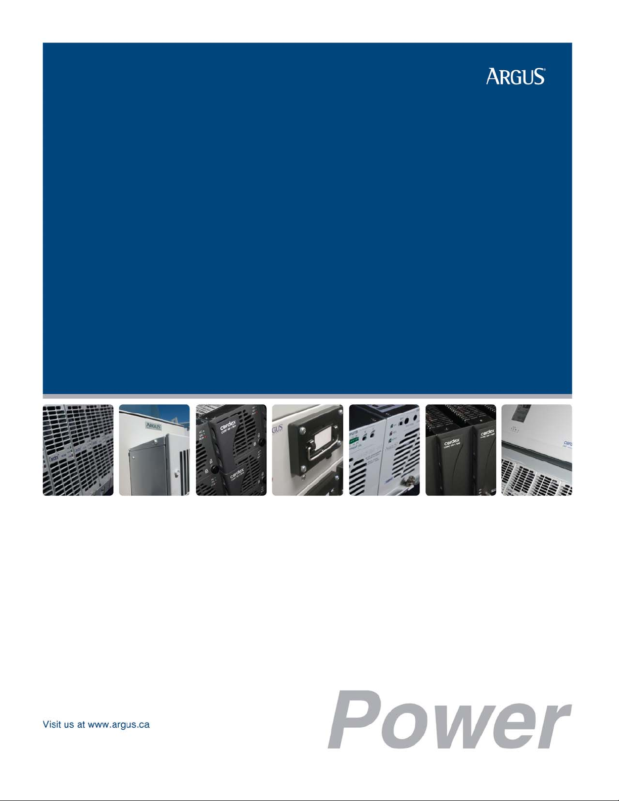
1.2 Product Overview
The CXPS 48-1T is a complete integrated 48Vdc power system with 375A initial capacity; expandable up to 600A.
The system utilizes the advanced Cordex controller and 48V 3.6kW rectifier modules. The one-tier (Vista II series)
distribution center provides front access for DC distribution, site controller, and battery connections.
Cordex rectifier modules use a high frequency, switched mode conversion technique to provide a fully regulated
and isolated DC output from the AC mains. The rectifier input is wide range to allow use on
208/220/230/240/277Vac 50/60Hz electrical service.
Rectifier power modules are “hot swappable” meaning they can be inserted or removed fro m the shelf without
cutting power to or from the system or the load.
NOTE: Rectifier modules are not included with the base system, but may be purchased along with the system at the time
of ordering or added after the shelf has been installed.
The shelf rectifier system is designed to operate with the
Argus Cordex System Controller (CXC).
This system uses the CXCM4 modular version of the
controller, which plugs directly into the Cordex rectifier
system shelf. The rectifier/shelf manual provides CXCM4
installation details.
The CXC allows the user to configure, monitor and control
the entire DC power system from its touch screen display
similar to that used in a personal digital assistant (PDA).
Other features of the unit include temperature
compensation, auto equalization, remote access, e-mail
alarm notification, battery diagnostics, as well as web
server and SNMP support for configuration and
monitoring.
Details of controller operation are provided in the
current version software manual.
Figure 1–Front angle view of the 053-392-20-000
rail mount CXPS 48-1T configuration
Argus Technologies Ltd. 053-392-C0 Rev A WC
Printed in Canada. © 2007 Argus Technologies Ltd. ARGUS and CORDEX are trademarks of Argus Technologies Ltd. All Rights Reserved. Page 1 of 31
Page 12

1.3 System Configurations
The system is available to order in the following configurations:
Description Part Number
CXPS 48-1T, Cordex base 48V 375A power system, 23” rail mount................................................ 053-392-20-000
CXPS 48-1T system with 22RU relay rack, battery mount................................................................ 053-392-20-010
CXPS 48-1T system with 7 foot Z4 relay rack................................................................................... 053-392-20-020
CXPS 48-1T system with 7 foot Z4 relay rack and 3x battery trays (3x strings) ............................... 053-392-20-030
1.4 Part Numbers and List Options
This product is available to order with the following options and accessories:
Description Part Number
Cordex 48-3.6kW rectifier power module (pre-RoHS 010-567-20).................................................... 010-600-20-040
CXPS 48V-24V converter integration kit, CSM02 6-module converter shelf............................................038-276-20
Rack, relay, 7 foot, 23", seismic zone 4............................................................................................. 030-638-20-023
Rack, battery mount, half-height, 23", 22RU ..................................................................................... 030-694-20-042
Breaker, AM-type mid-trip plug-in, 1A........................................................................................................470-300-10
Breaker, AM-type mid-trip plug-in, 3A........................................................................................................470-301-10
Breaker, AM-type mid-trip plug-in, 5A........................................................................................................470-302-10
Breaker, AM-type mid-trip plug-in, 10A......................................................................................................470-303-10
Breaker, AM-type mid-trip plug-in, 15A......................................................................................................470-304-10
Breaker, AM-type mid-trip plug-in, 20A......................................................................................................470-305-10
Breaker, AM-type mid-trip plug-in, 25A......................................................................................................470-306-10
Breaker, AM-type mid-trip plug-in, 30A......................................................................................................470-307-10
Breaker, AM-type mid-trip plug-in, 35A......................................................................................................470-308-10
Breaker, AM-type mid-trip plug-in, 40A......................................................................................................470-309-10
Breaker, AM-type mid-trip plug-in, 45A......................................................................................................470-310-10
Breaker, AM-type mid-trip plug-in, 50A......................................................................................................470-311-10
Breaker, AM-type mid-trip plug-in, 60A......................................................................................................470-312-10
Breaker, AM-type mid-trip plug-in, 70A......................................................................................................470-313-10
Breaker, AM-type mid-trip plug-in, 80A......................................................................................................470-314-10
Breaker, AM-type mid-trip plug-in, 90A......................................................................................................470-315-10
Breaker, AM-type mid-trip plug-in, 100A....................................................................................................470-316-10
Breaker, AM-type mid-trip plug-in, 110A (2-pole) ......................................................................................747-220-20
Breaker, AM-type mid-trip plug-in, 125A (2-pole) ......................................................................................747-147-20
Breaker, AM-type mid-trip plug-in, 150A (2-pole) ......................................................................................747-148-20
Breaker, AM-type mid-trip plug-in, 175A (3-pole) ......................................................................................747-149-20
Breaker, AM-type mid-trip plug-in, 200A (3-pole) ......................................................................................747-150-20
Breaker, AM-type mid-trip plug-in, 225A (3-pole) ......................................................................................747-200-20
Breaker, AM-type mid-trip plug-in, 250A (3-pole) ......................................................................................747-221-20
GMT fuse, 0.5A..........................................................................................................................................460-004-10
GMT fuse, 1A.............................................................................................................................................460-006-10
GMT fuse, 1.3A..........................................................................................................................................460-081-10
GMT fuse, 1.5A..........................................................................................................................................460-082-10
GMT fuse, 2A.............................................................................................................................................460-083-10
GMT fuse, 3A.............................................................................................................................................460-013-10
GMT fuse, 4A.............................................................................................................................................460-085-10
GMT fuse, 5A.............................................................................................................................................460-084-10
GMT fuse, 7.5A..........................................................................................................................................460-105-10
GMT fuse, 10A...........................................................................................................................................460-069-10
GMT fuse, 15A...........................................................................................................................................460-150-10
The above information is valid at the time of publication. Consult factory for up-to-date ordering information.
Argus Technologies Ltd. 053-392-C0 Rev A WC
Printed in Canada. © 2007 Argus Technologies Ltd. ARGUS and CORDEX are trademarks of Argus Technologies Ltd. All Rights Reserved. Page 2 of 31
Page 13
2 Features
2.1 System Overview
The basic system configuration is called out by Argus part number 053-392-2 0-000; which includes:
• 600A One-Tier Distribution Center (Vista II One-Tier UDC)
• Cordex System Modular Controller 4RU (CXCM4)
• One (1) Cordex 48-3.6kW 6-module rectifier shelf
• Kydex rear cover
• 23” rack mount rails
• System integration cabling and bus work.
Optional system configurations are available as:
053-392-20-010: basic configuration factory installed into a 22RU battery mount 23” relay rack.
053-392-20-020: basic configuration factory installed into a 7 foot 23” zone 4 relay rack.
053-392-20-030: basic configuration factory installed into a 7 foot 23” zone 4 relay rack and three (3) battery
trays with cabling and 100A battery disconnects for up to three (3) 48V VRLA strings.
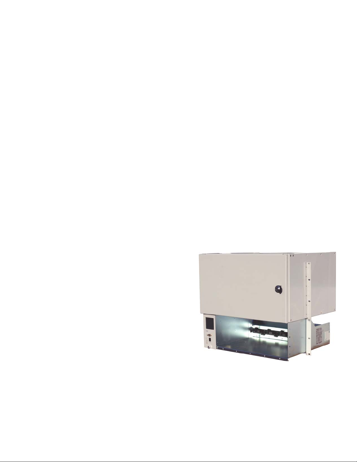
2.2 Tiered Distribution Features
2.2.1 Overview (Vista II One-Tier)
The 600A One Tier Distribution Center is a modular, front access system that provides DC distribution, rectifier
and battery connections. Coupled with Argus Cordex system controller, rectifiers and converters, it provides a
complete solution in a compact integrated package.
The distribution center in the CXPS 48-1T is configured at the factory with:
• 48V, 18-position split-breaker tier with 600A LVD (can also be configured for split 48V/24V voltage
applications)
• 48V, 10-position, 30A GMT fuse assembly
• Load shunt for current measurement.
The modular distribution center allows customization of integrated power systems; perfect for space-restricted
installs. The system provides front access to controller interface and I/O connections, load breakers & fuses, and
battery connections.
Figure 2–Example of distribution center in the CXPS 48-1T
Argus Technologies Ltd. 053-392-C0 Rev A WC
Printed in Canada. © 2007 Argus Technologies Ltd. ARGUS and CORDEX are trademarks of Argus Technologies Ltd. All Rights Reserved. Page 3 of 31
Page 14

2.2.2 DC Distribution Installed
2.2.2.1 Tier 1
The distribution tier in the CXPS 48-1T has support for eighteen (18) AM-type plug-in breaker
positions with an 800A shunt and 600A LVD. This option is a split-tier design – factory
configured – with a jumper to support eighteen (18) 48Vdc breaker positions.
The jumper is removable for future system installation / upgrade of 48V-24V converters.
Removing the jumper will change the tier capacity to eight (8) 48Vdc brea ker positions and ten
(10) 24Vdc breaker positions.
NOTE:
When implementing the 48/24V split distribution configuration, the LVD will only be in series with the 48V distribution
side. LVD for the 24V loads will be performed via the 48V input to the converter or via software at the converter level.
For split voltage modification of Tier 1, please reference the installation section of this manual.
2.2.2.2 GMT Fuse Block
A 10-position GMT fuse block is also factory installed and is configured for additional primary
voltage (48V) distribution. The GMT fuse block has a total capacity of 30A.
2.3 Cordex System Controller (CXC)
2.3.1 CXCM4 Overview
The CXCM4 (Cordex Controller, Modular, 4RU) is mounted in the rectifier system shelf and brings advanced
monitoring technology to the Cordex series of rectifiers. This compact system controlle r is designed for seamless
operation and set up of Argus power systems and is equipped with the complete range of Cordex software
features, including the following:
• Designed to communicate directly with Cordex rectifiers
• Includes battery temperature compensation charging
• Battery performance diagnostics
• Provides local and remote communications
• User definable alarms
• Daily logging of power system events and system statistics.
Behind the CXCM4’s front panel lies the main controller motherboard, which contains a microprocessor, memory,
as well as numerous other electronic components.
The CXCM4 includes a web server providing easy set up and monitoring using an Internet connection with the
standard Windows Internet Explorer browser.
The data logging feature allows the user to capture data from multiple inputs, for AC/DC voltages, load/battery
current, cell voltages & temperatures (automatically for up to 16 user defined logs). Typical applications of the
CXCM4 logging include power system details, thermal performance of outdoor enclosures, ba ttery cell specifics,
or mains variations captured by an AC voltage watchdog.
A built-in audio speaker sounds an intermittent tone during active alarms.
The input/output (I/O) board houses a series of terminal connections.
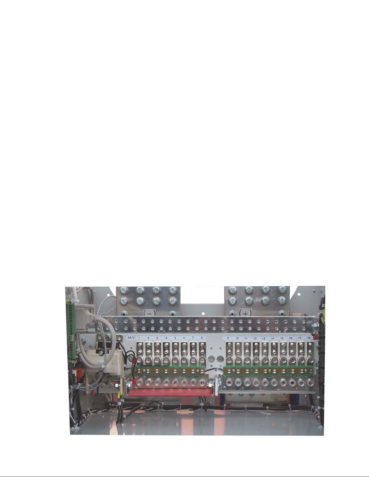
2.3.2 Front Panel
2.3.2.1 Display
Located on the front panel is a 160 x 160-pixel graphical LCD with touch screen similar to those
used in PDAs. This graphical user interface (GUI) allows the operator to interact with screen
selectable items using a fingertip.
Argus Technologies Ltd. 053-392-C0 Rev A WC
Printed in Canada. © 2007 Argus Technologies Ltd. ARGUS and CORDEX are trademarks of Argus Technologies Ltd. All Rights Reserved. Page 4 of 31
Page 15
Touch screen
RS-232 (craft port)
2.3.2.2 LEDs
The CXCM4 has three LEDs located on the front panel. These are used to displ ay the alarm
status of the power system, CXCM4 progress and status during startup, and file transfers.
Alarm Conditions
The CXCM4 illuminates the LED that corresponds to the system alarm statu s. T he following
show the corresponding alarm status for each LED color:
Green – OK, no alarms present
Yellow – Minor alarm is present (no major alarms)
Red – Major alarm is present.
Only one LED is illuminated at a time during alarm conditions.
Progress and Status Indication
The LEDs are also used in the following situations:
Base unit validation – all three LEDs are on at the same time.
File transfer – when recovering from invalid firmware application – the red LED is
illuminated.
Reset (RST) button
Ethernet port
System status LEDs
Figure 3–Cordex CXCM4 model system controller front panel
2.3.2.3 Reset
A reset button is located on the front panel for restarting the CXCM4’s microprocessor. It takes
approximately 15 seconds before the display reappears after pressing the reset button.
NOTE: Refer also to the software manual – always select the shutdown menu item before pressin g the reset
button.
2.3.2.4 Ethernet Port
The Ethernet port is designed for CXCM4 connection to a user supplied network (TCP/IP
secured by user) via a front panel RJ-45 jack and a standard network cable.
Local access (e.g. laptop computer) is also possible from the Ethernet port connection using a
standard network crossover cable.
2.3.2.5 RS-232 Serial (Craft) Port
Local access to the CXCM4 is possible through a front panel RS-232 serial port; using a null
modem cable. The communication protocol supports a web interface (via Microsoft® Internet
Explorer 6 or greater). The remote screen display is an enhanced version of the CXC’s front
panel display.
Argus Technologies Ltd. 053-392-C0 Rev A WC
Printed in Canada. © 2007 Argus Technologies Ltd. ARGUS and CORDEX are trademarks of Argus Technologies Ltd. All Rights Reserved. Page 5 of 31
Page 16

2.3.3 Analog Input Channels
The CXCM4 has analog input channels for voltage, current, and temperature.
2.3.3.1 Voltage Inputs
Two voltage input channels, V1 and V2, provide monitoring of discharge and charge voltage.
The CXCM4 software is pre-configured to monitor V2 for both load and battery voltage. V2 is
used as the system reference for rectifier float voltage, low voltage disconnect (LVD), system
high voltage alarm, and system low voltage alarm. V1 is available for additional voltage
measurements.
2.3.3.2 Current Inputs
The CXCM4 software is pre-configured to monitor for load current using an external 50mV
current shunt.
2.3.3.3 Temperature Inputs
Two temperature input channels, T1 and T2, provide monitoring of battery temperature and
temperature compensation (temp comp) or room/ambient temperature. A voltage is supplied by
the CXC to these terminals to power the temperature sensors.
2.3.4 Digital Input Channels
The CXCM4 can accommodate up to four channels and can monitor digital alarm/control signals from rectifiers,
converters and many other types of equipment.
2.3.5 Alarm and Control Output Relays
The CXCM4 contains eight Form C digital alarm output relays to extend alarms and control ex ternal apparatus.
Each internally generated alarm or control signal may be mapped to any one of the relays, or, several signals may
be mapped to just one relay or none at all.
2.3.5.1 LVD Control (External Option)
The LVD Control functions can be hardwired directly from the assigned relay output to an
optional LVD override control and distribution alarm card. This provides a safety measure to
protect against load disconnect during CXCM4 reset or replacement; e.g. when the controller is
off-line. Operators may also perform test and maintenance procedures on the CXCM4 without
disturbing the load.
2.3.6 System Fail Alarm/Relay
The CXCM4 system fail alarm (K0) activates because of a major internal failure. Durin g such a condition, the unit
will attempt to reset, but if this fails, an alarm condition will be extended to a relay and the red LED on the front
panel will illuminate. This is a fail-safe signal to the remote monitoring equipment; i.e. alarm will be extended even
if power to the unit is interrupted.
2.3.7 Network Connection and Remote Communications
The Cordex system can be set up, monitored and tested via ETHERNET 10/100 Base-T serial data connec tion.
The communication protocol supports a web interface. All alarming and control of Cordex rectifiers is
accomplished with a CXC via a CAN bus.
A step-by-step connection wizard – provided to establish remote communications with your CXC – is available via
the Argus website (www.argusdcpower.com).
Argus Technologies Ltd. 053-392-C0 Rev A WC
Printed in Canada. © 2007 Argus Technologies Ltd. ARGUS and CORDEX are trademarks of Argus Technologies Ltd. All Rights Reserved. Page 6 of 31
Page 17

2.4 Cordex 48-3.6kW Rectifiers
2.4.1 Rectifier Overview
The CXPS 48-1T system is provisioned for use with the high-density Cordex 48-3.6kW rectifier system. The
system ships complete with one (1) 23” 6-module rectifier shelf installed. Individual 3.6kW (75A) rectifiers are
ordered separately.
NOTE: The one (1) installed 6-module shelf with one CXCM4 (controller) allow for up to five (5) 3.6kW modules in a
single 375A system. Distribution and buswork capacity allows for a total system load ca pacity of up to 600A with
the installation of an additional rectifier shelf.
2.4.2 Remote Control
All alarming and control of Cordex rectifiers is accomplished with a CXC via a CAN bus. The Cordex rectifier
shelves provide connections for serial communications with other rectifier shelves as well as supervisory and
control panels.
2.4.3 Rectifier Front Panel
LEDs
Thumbscrew
Figure 4–Cordex 48-3.6kW modular switched mode rectifier
2.4.3.1 LEDs
The front panel LEDs provide:
• Rectifier status summary,
• Rectifier software upgrade in progress indication,
• Locate module pattern.
Rectifier status summary will show the rectifier alarm status, communication fail status and
rectifier on/off status.
AC ON
The top LED (green) is on when AC is within valid range. The LED will flash (twice per second)
when AC is outside the nominal range – AC voltage is invalid if the AC Mains Low or AC
Mains High alarm is active. The LED turns off when AC has failed.
Argus Technologies Ltd. 053-392-C0 Rev A WC
Printed in Canada. © 2007 Argus Technologies Ltd. ARGUS and CORDEX are trademarks of Argus Technologies Ltd. All Rights Reserved. Page 7 of 31
Page 18

DC ON
The middle LED (green) is on when the rectifier is delivering power to the load. The LED turns
off when the rectifier is off; e.g., when commanded via the CXC.
ALARM
The bottom LED (red) is on continuously in the event of an active Module Fail alarm; if the
module is unable to source power as a result of any of the following conditions:
Output fuse blown AC Mains Input Fail Module fail (ramp test fail)
High voltage (OVP) shutdown Thermal shutdown Local shutdown
UPF fail No output power Fan (1 and 2) fail.
The LED will flash (twice per second) when a minor alarm is detected; if the modules output
capability has been reduced or a minor component failure is detected during the following
conditions:
VAC meter fail AC foldback Remote equalize
Fan (1 or 2) fail Low output voltage High output voltage
Current limit (programmable option) Power limit (programmable option) High temperature foldback
Temperature sense fail Soft start operation Communications lost.
The LED remains off in the absence of an alarm. If the unit output is not connected to a battery
or parallel rectifier, the LED will extinguish if no AC power is present.
LED Activity During Software Upload
When a rectifier software upload is in progress, the LEDs will behave in a distinctly different way
to indicate new rectifier software is being transferred from the CXC.
When a rectifier data transfer is in progress, all three LEDs will flash in a sequence lasting 1.5
seconds. When the last LED is lit, the sequence is repeated beginning at the first LED.
LED Activity During ‘Locate Module’ Command from CXC
When the ‘locate module’ command has been received from the CXC, the LEDs will behave in
another distinct fashion so that the rectifier is easier to visually identify among adjacent
rectifiers.
This state is entered when commanded via the CXC. The LEDs will flash in a ping-pong pattern
repeating every 2 seconds.
The ping-pong pattern lights each LED sequentially. After the last LED is lit, each LED is lit in
reverse sequence. When the first LED is lit, the pattern repeats. The effect makes it appear as if
the light is bouncing between the first and last LED.
2.4.3.2 Mechanical
A thumbscrew is provided to secure the rectifier into the shelf. During normal operation the
rectifier shall be locked into position. A handle (or grip) is incorporated into the front panel to
facilitate the removal of the rectifier from the shelf. No special tools are required.
2.4.4 Rectifier Rear Panel
Located on the rear panel of the rectifier is a single connector for shelf power and communications.
2.4.5 True Module Fail Alarm
The power modules have a “true” fail alarm. This provides a true indication of the power module’s ability to source
current. When the module’s output current drops below 2.5% of the rated output a low output current condition is
detected and the Module Fail detection circuit is activated. This circuit momentarily ramps up the output voltage to
determine if the module will source current. If no increase in current is detected, the Module Fail alarm is
activated. The module will test once every 60 seconds for the condition until current is detected. Output voltage
ramping will cease upon detection of current
1
. A minimum 2.5% load is required to avoid the Ramp Test Fail
alarm; this can typically be provided with the parallel system battery. Activation of this alarm could indicate a failed
module or a failed load.
1
Under normal conditions, a battery connected to the output of the rectifier will draw current when the voltage ramp occurs. Therefore the rectifier fail
alarm will not be generated with a battery connected.
Argus Technologies Ltd. 053-392-C0 Rev A WC
Printed in Canada. © 2007 Argus Technologies Ltd. ARGUS and CORDEX are trademarks of Argus Technologies Ltd. All Rights Reserved. Page 8 of 31
Page 19

NOTE: For Cordex rectifier systems without batteries (or with a very light load; below 2.5% of rated output) it is
recommended that the ramp test be disabled to avoid nuisance alarms. The Ra mp Test feature is
enabled/disabled via the CXC menu item: Rectifiers, Configure Settings.
2.4.6 Heat Dissipation
Each rectifier module is equipped with at least one front-mounted fan. The fan operates at temperatures above
0°C (32°F). Cooling of the module is front-to-rear with the exhaust air exiting at the back. The fan is variable
speed; which is determined by heatsink temperature and load.
2.4.7 Over Temperature Protection
Each rectifier module is protected in the event of an excessive increase in temperature due to component failure
or cooling airflow blockage. During over temperature conditions, the rectifier limits the output power as well as the
output current. If temperature continues to increase, a shutdown of the rectifier is initiated. The rectifier shall
restart automatically if the temperature has returned to a safe level.
2.4.8 Wide AC Range
A minor alarm is generated when the AC input voltage drops below specification. Rectifier output power is
reduced linearly between 176Vac and 150Vac to 75% of the rated output power (the unit will deliver derated
output power down to 90Vac).
At 90Vac, the module will shut down and will not restart until the AC is greater than or equal to 150Vac; however,
the restart voltage depends on the load current. At reduced load current the unit may restart with the input voltage
as low as 100Vac.
For voltages above 277Vac, power factor and total harmonic distortion may be derated. Up to 320Vac, the
rectifier will be operational and shall not suffer any damage.
2.4.9 AC Inrush/Transient Suppression
The inrush current of the rectifier module is limited to the full load steady state line current to prevent surge on the
AC line. Modules are also protected from input lightning and transient surges in accordance with IEEE/ANSI
C62.41 Category B3.
2.4.10 Soft Start
To eliminate an instantaneous demand on the AC source, a soft start feature is employed. Soft Start, sometimes
referred to as “current walk-in”, works by gradually (up to five seconds) ramping the current limit up from zero to
the actual or defined customer setting. The rectifier output voltage is ramped up from the minimum voltage to the
float voltage.
2.4.11 Start Delay
The rectifier modules are equipped with a delay timer in order to stagger start a series of modules to prev ent
excessive loading of generators upon start up. The built-in timer delays the turn on of the module depending on
the value selected (up to 120 seconds) via the CXC. A minimum one-second delay is preset to allow charging of
the input capacitors.
2.4.12 Current Limit/Short Circuit Protection
The current limit function determines the maximum output current limit of the rectifier module, regardless of output
voltage or power. Maximum output current is limited to a constant value down to short circuit condition. Current
limiting can be used to mate the rectifier output current ampacity to the needs of the load and parallel battery to
minimize excessive battery recharge current.
The rectifier will sustain a short circuit at the output terminals indefinitely. The maximum short circuit current shall
not exceed 105% of the rated full load current.
Argus Technologies Ltd. 053-392-C0 Rev A WC
Printed in Canada. © 2007 Argus Technologies Ltd. ARGUS and CORDEX are trademarks of Argus Technologies Ltd. All Rights Reserved. Page 9 of 31
Page 20

2.4.13 Power Limiting
Each rectifier module is designed to limit power output to the module specification. This enables more current to
be supplied at lower output voltages, and allows matching of output to the demand of constant power loads,
normally seen with telecom equipment.
This feature may also be used for a faster recharge of flooded batteries paralleled with the load.
NOTE: Current limiting overrides the power-limiting feature.
2.4.14 High Voltage Shutdown (HVSD)
This feature provides protection to the load from over voltage conditions originating from the rectifiers. It operates
by shutting down the offending rectifier module when a high output voltage condition occurs. Indication is through
the red Alarm (Module Fail) LED. Modules will restart automatically; however, if more than three over voltage
conditions occur in one minute, the module will latch off and remain shut down until it is reset (by restarting the
rectifier) via the CXC.
2.4.15 Battery Eliminator Operation
Rectifier modules maintain all specifications (except where indicated) with or without a battery attached in parallel
to the output; however, if a battery or another module supplying DC voltage in parallel is not present, there will be
no monitoring or control activity if there is an AC power failure or input fuse failure.
Please see our website at www.argusdcpower.com for details on other custom products from Argus Tech nologies .
Argus Technologies Ltd. 053-392-C0 Rev A WC
Printed in Canada. © 2007 Argus Technologies Ltd. ARGUS and CORDEX are trademarks of Argus Technologies Ltd. All Rights Reserved. Page 10 of 31
Page 21

3 Inspection
3.1 Packing Materials
All Argus products are shipped in rugged, double walled boxes and suspended via solid inserts to minimize shock
that may occur during transportation. Packaging assemblies and methods are tested to International Safe Transit
Association standards. Power systems are custom packaged in heavy-duty plywood crates.
Products are also packaged with Cortex. This plastic wrap contains a corrosive-inhibitor that protects the product
from corrosion for up to two years.
NOTE: Rectifiers and batteries are shipped on individual pallets and are packaged per manufacturer’s guidelines.
3.1.1 Returns for Service
Save the original shipping container. If the product needs to be returned for service, it should be packaged in its
original shipping container. If the original container is unavailable, make sure the product is packed with at least
three inches of shock-absorbing material to prevent shipping damage.
NOTE: Argus Technologies is not responsible for damage caused by the improper packaging of returned products.
3.2 Check for Damage
Prior to unpacking the product, note any damage to the shipping container. Unpack the product and inspe c t the
exterior for damage. If any damage is observed contact the carrier immediately.
Continue the inspection for any internal damage. In the unlikely event of internal damage, please inform the
carrier and contact Argus Technologies for advice on the impa ct of any damage.
3.3 General Receipt of Shipment
NOTE: The inventory included with your shipment is dependant upon the options you have ordered. The options ar e
clearly marked in the bill of materials at the back of this manual and on the labels on the shipping containers.
3.3.1 Racks
Consult the packing slip and power system bill of materials to verify that you have the correct number of racks per
your order.
3.3.2 Rectifiers (Purchased Separately)
Consult the packing slip to verify that you have the correct number of rectifiers per your order.
3.3.3 Miscellaneous Small Parts
Review the packing slip and bill of materials to determine the part number of the “configuration kits” included with
your system; e.g., 053-392-20-010 for CXPS 48-1T system with 22RU battery-mount relay rack.
Review the bill of materials (per the configuration kits that you determined above) to verify all the small parts are
included.
3.3.4 Batteries (Purchased Separately)
Verify that you have the correct number of batteries (if applicable). Refer to packing list.
Verify that you have all the necessary parts per your order for proper assembly.
Call Argus Technologies if you have any questions before you proceed: 1 (888) 462-7487
Argus Technologies Ltd. 053-392-C0 Rev A WC
Printed in Canada. © 2007 Argus Technologies Ltd. ARGUS and CORDEX are trademarks of Argus Technologies Ltd. All Rights Reserved. Page 11 of 31
Page 22

4 Installation
This chapter is provided for qualified personnel to install and interconnect the power compone nts within the Argus
power system. Regarding battery installation, refer primarily to the manufacturer’s guidelines for more specific
information.
NOTE: To aid the user with installation, frequent reference is made to drawings located at the rear of this manual.
4.1 Safety Precautions
Refer to the Important Safety Instructions near the front of this manual.
4.2 Tools Required
Various insulated tools are essential for DC power system installation. Use this list as a guide:
• Battery lifting apparatus (as required)
• Electric drill with hammer action, 1/2" capacity
• Various crimping tools and dies, to match lugs used in installation
• Load bank of sufficient capacity to load largest rectifier into current limit
• Digital voltmeter equipped with test leads
• Cable cutters
• Torque wrench: 1/4” drive, 0-150 in./lb.
• Torque wrench: 3/8” drive, 0-100 ft./lb.
• Insulating canvases as required (2’ x 2’, 1’ x 1’, 3’ x 3’, etc.)
• Various insulated hand tools (see Figure 5) including:
-Combination wrenches -Ratchet and socket set
-Various screwdrivers -Electricians knife
• Battery safety spill kit (required for wet cells only) including:
-Protective clothing -Face shields
-Gloves -Baking soda
-Eye wash equipment
• Cutters and wire strippers (#14 to #22 AWG) [2.5 to 0.34mm
2
].
Figure 5–Example of an insulated tool kit
Argus Technologies Ltd. 053-392-C0 Rev A WC
Printed in Canada. © 2007 Argus Technologies Ltd. ARGUS and CORDEX are trademarks of Argus Technologies Ltd. All Rights Reserved. Page 12 of 31
Page 23

4.3 Power System Assembly and Mounting
The power system must be mounted in a clean and dry environment. Sufficient free space must be provided at
the front and rear of the power system. This is to meet the cooling requirements of the rectifiers utilized in the
power system and to allow easy access to the power system components.
4.3.1 Rack Mounted Systems
Attach the power system to the customer-provided relay rack using mounting screws and star washers to ensure
an electrical bond between system chassis and relay rack.
4.3.2 Floor Mounted Systems
Secure the system to a concrete floor utilizing either heavy duty anchors (1/2” x 2-1/2”) or, for wooden floors,
heavy-duty lag screws (5/8” x 2-1/2”). Use appropriately sized flat washers.
Use isolating kits if required to isolate system from the floor.
It is recommended that the relay rack be secured to the overhead cable tray. Argus does not supply the
mechanical details necessary for overhead support.
4.3.3 Half-Rack/Battery Mounted Systems
Obtain the appropriate battery to power system adapter plate. Secure the plate to the battery stack using heavy
duty hardware.
Secure the power system to the adapter plate using heavy duty hardware.
It is recommended that the power system be secured to the overhead cable tray. Argus doe s not sup ply the
mechanical details necessary for overhead support.
4.4 Rectifier Module Insertion/Removal
Insert by placing the rectifier module on the shelf bottom and sliding the module into the rear connector (insi de of
the shelf). Apply pressure on the module handle to engage the rear connector in the shelf receptacle.
NOTE: It is recommended that the first module be inserted into the front leftmost position using the side of the shelf as a
guide. Subsequent modules may be inserted using the previous module as a guide.
Tighten the screw on the bottom of the faceplate to secure the module to the shelf.
NOTE: Do not force a module into position if it does not seat properly. All modules are keyed to ensure that the correct
module (voltage/polarity) type is used.
To remove a module, loosen the screw on the bottom of the faceplate. Grasp handle and pull out, sliding the
module away from the rear connector and out of the shelf.
Argus Technologies Ltd. 053-392-C0 Rev A WC
Printed in Canada. © 2007 Argus Technologies Ltd. ARGUS and CORDEX are trademarks of Argus Technologies Ltd. All Rights Reserved. Page 13 of 31
Page 24

4.5 Battery Installation
This information is provided as a guideline and is not meant to imply that batteries are part of this power system.
WARNING
Follow battery manufacturer’s safety recommendations when working around battery systems
and review the safety instructions provided in this manual.
4.5.1 Preparation/Mounting
Batteries should be located in a temperature-controlled environment. The temperature should be regulated at
approx. 25°C (77°F). Significantly lower temperatures reduce performance and higher temperatures decrease life
expectancy.
Provide adequate ventilation. VRLA batteries, though not requiring the special ventilation requirements of a
flooded battery, should not be installed in an airtight enclosure. Hydrogen gas may be vented in a fault condition;
i.e., failed battery.
Before assembly, clean cells (where applicable) as per the battery manufacturer's recommendations.
First neutralize any acid with a baking soda and water solution. Then wipe the cells with clean water.
4.5.2 Installation of Batteries
Verify that all battery breakers, DC circuit breakers, and fuses on the distribution panels are either
in the OFF position or removed.
Use a corrosion-inhibiting agent, such as NO-OX-ID “A”™, on all battery terminal connections.
1. Assemble battery rack (if required) and the cells or mono-blocks as per the
installation instructions supplied with the batteries.
2. Ensure that the battery output cabling will reach the [+] and [–] terminals of the series
battery string and that the batteries are oriented correctly for easy installation of the
inter-unit “series” connectors.
3. Remove any NO-OX-ID “A”™ grease from battery terminals.
4. Burnish terminal posts with a non-metallic brush, polishing pad or 3M Scotch Brite™
scouring pad.
5. Apply a light coating of NO-OX-ID “A”™ grease to the terminal posts.
6. If lead plated inter-unit connectors are used, they should also be burnished and NOOX-ID “A”™ grease applied as above. Install the inter-unit connectors.
7. After all battery connections are completed, torque per battery specifications
(typically 100 in-lbs).
NOTE: See system startup procedure before connecting batteries online.
Argus Technologies Ltd. 053-392-C0 Rev A WC
Printed in Canada. © 2007 Argus Technologies Ltd. ARGUS and CORDEX are trademarks of Argus Technologies Ltd. All Rights Reserved. Page 14 of 31
Page 25

After assembly, batteries should be numbered and “as received” readings taken, including specific gravity, cell
voltage and temperature. One cell will be designated as the pilot cell; this is usually the cell with either the lowest
specific gravity or voltage. Refer to manufacturer's literature for guidelines. See following table for typical
maintenance report:
Company: ________________________________________________ Date: ____________________
Address:____________________________________________________________________________
Battery location and/or number:__________________________________________________________
No. of cells: _______________ Type: __________________________ Date new: ________________
Date installed: _____________ Float voltage: ____________________ Ambient temp.: ____________
Cell Readings
Cell # Serial # Voltage Specific
Gravity
1
2
3
4
5
6
7
8
9
10
11
12
13
14
15
16
17
18
19
20
21
22
23
24
Ohms Mhos Observations
Remarks and recommendations:_________________________________________________________
__________________________________________________________________________________
__________________________________________________________________________________
Readings taken by: _________________________________________
Table A–Typical VRLA battery maintenance report
Argus Technologies Ltd. 053-392-C0 Rev A WC
Printed in Canada. © 2007 Argus Technologies Ltd. ARGUS and CORDEX are trademarks of Argus Technologies Ltd. All Rights Reserved. Page 15 of 31
Page 26

5 Wiring
This chapter provides cabling details and notes on cable sizing for DC a pplications with respect to the product.
WARNING
Ensure that power is removed by turning off rectifiers and removing battery line fuse or
connection before attempting work on the wiring connections. Use a voltmeter to verify the
absence of voltage. Clearly mark the correct polarity of the battery leads before commencing work
on DC connections.
Refer to the previous (Installation) chapter for safety precautions and tools required.
5.1 Grounding
The isolated power system battery return bus (BRB) should be connected to the building master ground bus
(MGB) or floor ground bus (FGB) in a larger building. This acts as a system reference and as a low imp edance
path to ground for surges, transients, noise, etc. The MGB or FGB should have a direct low impedance path to
the building grounding system. The cable from the power system to the MGB or FGB should be sized to provide
sufficient ampacity to clear the largest fuse or breaker on the power system, excluding the battery protection fuse
or circuit breaker. This is the minimum requirement; other factors including length of cable and special grounding
requirements of the load should also be factored in. The insulated cable should be equipped with two-hole crimp
type lugs and should not have any tight bends or kinks.
Power System Ampacity Ground Reference Conductor Size
< 30A #10
30 – 100A #6-2
100 – 400A 0000
400 – 800A 350 MCM
> 800A 750 MCM
Table B–Typical ground reference conductor selection
The power system frame must also be connected to the MGB or FGB. This is done for personnel safety and to
meet many Telco grounding requirements. Each bay should have its own frame or site ground connection (see
Figure 6). Refer also to the Customer Connections drawing at the rear of the manual.
5.2 AC Feeder Protection/Sizing
To maximize system reliability, each power module should be fed from a dedicated protection feeder breaker
located at the AC distribution panel. The feeder breaker can also act as the disconnect device for the connected
module. Refer to the specifications at the front of this manual for Argus recommendations.
5.3 AC Input Connections
CAUTION: AC input wires should be routed in flexible or rigid conduit as far away as possible
from the DC power wires to minimize EMI disturbances.
Ensure all modules are removed from the shelf and refer to the Customer Connections drawing at the rear of the
manual for AC terminal block location.
Remove the covers (2 places) from the rear of the shelf to expose the AC input terminal blocks, L1 and L2 for
each rectifier. Each terminal pair relates to an individual power module as marked.
WARNING
Use care when removing or replacing the covers for the AC input connections. Never assume that
an electrical connection or conductor is not energized.
The wireway is designed for two customer-supplied 1” conduit fittings for AC supply located one on each side of
the shelf. Attach the conduit retainers to the wireway hole(s) and route the AC cables through. Secure the wire s to
the AC input and chassis ground terminals as required. Tighten the cable con nector to the AC cable (conduit
similar).
Replace rear cover(s) once all connections have been completed.
Argus Technologies Ltd. 053-392-C0 Rev A WC
Printed in Canada. © 2007 Argus Technologies Ltd. ARGUS and CORDEX are trademarks of Argus Technologies Ltd. All Rights Reserved. Page 16 of 31
Page 27

t
5.4 DC Output Connections
WARNING
Leave cables or bus bars disconnected at battery and verify output polarity using a voltmeter.
Make battery connections only after all other wiring is completed.
DC output wire shall be UL approved XHHW or RHH/RHW (for Canadian users, RW90 Type). Control and sense
wires shall be UL approved Style 1015 (for Canadian users, TEW type).
The common output leg of the rectifier system should be connected to ground. This is typically done at the load
common termination point.
5.4.1 Battery Connections
Battery cables should be sized for a 0.25 V drop from battery to the power system at full load including anticipated
growth. The cables should also meet ampacity requirements. Cables terminating directly on battery posts or
connection details should be secured so that there is no stress on the battery posts. Lead plated lugs and lead
plated or stainless steel hardware should be used on all terminations at vented batteries to reduce corrosion.
Prepare, route and connect cables from power system to battery termination details. Terminating points should be
burnished and a corrosion-inhibiting agent, such as NO-OX-ID “A”™, should be applied to all battery terminal
connections.
The 600A One Tier Distribution Center (Vista II One-Tier UDC) allows for (4) sets of battery connections for both
hot and return. Connections allow for 3/8” on 1”C lug connections.
Ho
Return
Site Ground
Figure 6–Vista II one-tier battery connections (hot and return)
NOTE: Final connection to battery live should not be made, insulate and leave disconnected or remove the battery fuses.
Switch battery contactors off (if used). See system startup procedure before connecting batteries online.
5.4.1.1 Back-To-Back Connections
To allow for back-to-back connections on the battery bus bars, the PEM nuts must be removed
from rear side of each bar. This requires rear access to the system. Reference Figure 7 for PEM
nut removal detail.
Argus Technologies Ltd. 053-392-C0 Rev A WC
Printed in Canada. © 2007 Argus Technologies Ltd. ARGUS and CORDEX are trademarks of Argus Technologies Ltd. All Rights Reserved. Page 17 of 31
Page 28

To remove PEM nuts:
1. Place a 9/16" socket over the PEM nut to be removed.
2. Insert a 3/8" bolt through the socket and thread into the PEM nut.
3. Using a socket wrench with a 9/16" drive, tighten the head of the bolt until the action pulls the
PEM nut from the bus bar.
Figure 7–PEM nut removal for back-to-back connections on the battery bus bars
5.4.2 Load Distribution
Bolt through socket
PEM removed
Refer to guidelines supplied with the load equipment. Typically distribution cables are sized to provide a 0.5 V
loop drop at full load as well as meeting ampacity requirements of the protection fuse or circuit breaker.
5.4.2.1 AM Breakers
The CXPS 48-1T is factory configured with (18) total single-pole AM-type plug-in breaker
positions for 48V load distribution. The breakers have bullet terminals, which plug into the
breaker tier for simple installation and removal. Each distribution tier has a 1/4” – 5/8”C hole set
for the breaker output and on the ground bar located directly above the breaker panel.
• 1 to 100 amp breakers require 1 position.
• 110 to 150 amp breakers require 2 positions*.
• 175 and 200 amp breakers require 3 positions*.
* 2-position and 3-position breakers have an output adapter that provides a single 3/8" hole on a 1" center output.
The return must use one of the battery or rectifier terminations.
Figure 8–Front view of the 2-Pole and 3-Pole output adapters
It is recommended to install the largest capacity circuit breakers on the top distribution tier to
optimize cable management. It is imperative to plan circuit breaker installation to allow for
Argus Technologies Ltd. 053-392-C0 Rev A WC
Printed in Canada. © 2007 Argus Technologies Ltd. ARGUS and CORDEX are trademarks of Argus Technologies Ltd. All Rights Reserved. Page 18 of 31
Page 29

proper cable management and to not overload the capacity of a single tier (600A LVD
limitation).
TPS fuses may be used instead of breakers via a plug-in breaker cartridge, which installs into
any AM-type plug-in breaker panel configuration. See Figure 9 below:
Figure 9–Plug-in breaker/fuse cartridge
5.4.2.2 GMT Fuses
The CXPS 48-1T is factory configured with (10) GMT type fuse positions for additional 48V load
distribution. The fuse assembly is rated for maximum capacity of 30A.
Connections for hot and return are made via screw terminal connections on the assembly.
5.5 DC-DC Converter Connections
The CXPS 48-1T is factory configured as a 48Vdc power system. A dual 48/24V output option is available via
factory or field upgrade with DC-DC converters.
Reference the DC-DC converter manual for full installation and operation proced ures.
Figure 10–GMT fuses
Argus Technologies Ltd. 053-392-C0 Rev A WC
Printed in Canada. © 2007 Argus Technologies Ltd. ARGUS and CORDEX are trademarks of Argus Technologies Ltd. All Rights Reserved. Page 19 of 31
Page 30

5.5.1 Re-Configure Split Tier Distribution
1. Remove the copper jumper bridging the 8-position and 10-position breaker rows.
2. Locate the alarm card on the left hand side of the internal wall of the distribution
center. Reference the Customer Connections drawing at the rear of the manual.
3. Locate the terminal blocks. The 10-position breaker alarming – factory configured for
48V distribution – is wired to TB12-42 “Pri Alm In.” Refer to the system schematic
located at the rear of this manual for terminal block location and factory wiring.
4. Remove the alarm wire and re-terminate to TB12-43 “Sec Alm In.”
5.5.2 Argus CSM02 Six-Module Converter Shelf Installation Method Of Procedure (MOP)
The CSM02 six-module converter shelf kit, # 038-276-20, includes a cable kit for integration into a CXPS 48-1T
power system. Please reference CSM02 manual # 012-502-B2 for drawings, specifications, and operation of
converter system. Please also reference schematic included with 038-276-20 kit for detailed wiring instructions.
NOTE: Rear access to CXPS system is required for this installation.
The kit includes:
• One six-module CSM02 23” converter shelf
• One 50A plug-in feeder breaker
• Two converter input cables (+/–), #6 AWG flex cable, pre-terminated with 1/4”-5/8”C
lugs on converter shelf end (un-terminated on other)
• Two converter output cables (+/–), #2 AWG flex cable, pre-terminated with 1/4”-5/8”C
lugs on converter shelf end (un-terminated on other)
• Two loose 1/4”-5/8”C lugs for terminating #6 AWG converter input cabling to Vista II
UDC (requires customer supplied crimp tool)
• Two loose 3/8”-1”C lugs for terminating #2 AWG converter output cabling to Vista II
UDC (requires customer supplied crimp tool)
• Hardware for attaching -GND converter output cable to Vista II UDC return bus
• Two #18 AWG signal cables for connecting converter fail alarm (digital) signal to
controller.
5.5.2.1 Installation Procedure
Preparation
Mount converter shelf into 23” rack channels below the CXPS power system leaving 1 RU
space between converter shelf and bottom of rectifier shelf for cooling.
Remove the rear panel of the converter shelf.
Insert the pre-terminated lug ends of the two #2 AWG cables into the converter output wireway
on the right hand side of the shelf.
Insert the pre-terminated lug ends of the two #6 AWG cables into the converter input wireway
on the left hand side of the shelf.
Converter Output Cabling (-GND Connection)
Terminate the #2 AWG cable with pre-terminated 1/4”-5/8”C lug (with wire marker #15) to the
-GND output terminal labeled “E4” using hardware supplied with shelf.
Route the un-terminated wire end up to the system return bus, cut wire to size, strip cable
sheath, crimp supplied 3/8”-1”C lug.
Attach to system return bus bar as per Figure 11 using hardware supplied with kit.
Argus Technologies Ltd. 053-392-C0 Rev A WC
Printed in Canada. © 2007 Argus Technologies Ltd. ARGUS and CORDEX are trademarks of Argus Technologies Ltd. All Rights Reserved. Page 20 of 31
Page 31

Converter output (-GND)
wire connection location
Converter output (+24V)
wire routing location
Figure 11–Rear of CXPS 48-1T system showing converter -GND output connection
and converter +24V wire routing location
Converter Output Cabling (+24V HOT Connection)
Terminate the #2 AWG cable with pre-terminated 1/4”-5/8”C lug (With wire marke r #16) to the
+24V (hot) output terminal labeled “E3” using hardware supplied with shelf.
Route the un-terminated wire end up in between the system bus bars towards the front of the
distribution center (reference Figure 11 for routing location).
Fish the wire through the existing hole in the glastic insulator of the distribution center
(reference Figure 12 for routing location).
Cut wire to size, strip cable sheath, and crimp supplied 3/8”-1 ”C lug. Note: This lug must be
crimped after it has been routed through the distribution center.
Attach lug to input bar using the hardware originally used for attaching copper jumper bar.
Argus Technologies Ltd. 053-392-C0 Rev A WC
Printed in Canada. © 2007 Argus Technologies Ltd. ARGUS and CORDEX are trademarks of Argus Technologies Ltd. All Rights Reserved. Page 21 of 31
Page 32

y
Converter output (+24V)
wirewa
Converter output (+24V)
wire connection
(jumper bar removed)
Figure 12–Connection points and wire routing for +24V input into split tier distribution
Converter Input Cabling (+GND Connection)
Terminate the #6 AWG cable with pre-terminated 1/4”-5/8”C lug (with wire marker #13) to the
+GND input terminal labeled “E2” using hardware supplied with shelf.
Route the un-terminated wire end up behind the CXPS system over the top of the distribution
center.
Cut wire to size, strip cable sheath, and crimp supplied 1/4”-5/8 ”C lug.
Attach lug to distribution tier return bar. Use the hardware supplied with the CXPS system for
attaching lug.
Converter Input Cabling (-48V Connection)
Terminate the #6 AWG cable with pre-terminated 1/4”-5/8”C lug (with wire marker #14) to the
-48V (hot) input terminal labeled “E1” using hardware supplied with shelf.
Route the un-terminated wire end up behind the CXPS system over the top of the distribution
center.
Cut wire to size, strip cable sheath, and crimp supplied 1/4”-5/8 ”C lug.
Attach lug to breaker output terminal. Use the hardware supplied with the CXPS system for
attaching lug (reference Figure 12 for breaker locations).
Ensure that converter input breaker is installed on –48V output section (breakers 1 through 8).
5.5.2.2 Converter Fail Alarm
Locate #18 AWG wire with tag #17
Attach end with ring lug to -GND output terminal on converter shelf (E4).
Attach unterminated wire end to TB2-8 “Conv Fail” on alarm connection at rear of CSM02 shelf.
Locate #18 AWG wire with tag #18
Attach unterminated wire end to TB2-7 “Conv Fail” on alarm connection at rear of CSM02 shelf.
Attach other unterminated wire end to TB11-36 “Conv Fail” on internal alarm board with Vista II
UDC (reference Figure 13 for alarm board details as well as -08 connection drawing at rear of
this manual).
5.5.2.3 Final Steps
Reattach back cover to converter shelf.
Install breakers as needed in 10-position breaker tier for required 24V distribution.
Cable from 24V loads to distribution as required.
Plug in 50A 48V feeder breaker into distribution tier.
Switch 50A feeder breaker to “ON” position to supply power to converter shelf.
Refer to Cordex Controller Software manual for custom alarming options using the two new
digital alarms (+24V distribution and converter fail).
Argus Technologies Ltd. 053-392-C0 Rev A WC
Printed in Canada. © 2007 Argus Technologies Ltd. ARGUS and CORDEX are trademarks of Argus Technologies Ltd. All Rights Reserved. Page 22 of 31
Page 33

A
5.6 Controller I/O Connections
WARNING
Ensure that input power and output power is removed before attempting work on the CXC’s wiring
connections.
System integration cabling is utilized to bring the controller I/O connections to the front (left side) of the distribution
center:
Relay outputs
Analog inputs
Digital inputs
5.6.1 Analog Inputs
WARNING
Ensure the correct polarity is used for all input cable terminations.
UTO IN (green) LED
LVD control switch
OVERRIDE IN or Inhibit
(yellow) LED
Figure 13–Controller I/O connections and LVD control card
(illustration only and may not match your installation)
The analog input channels are used to monitor various types of electrical signals. Some of the analog channels
are reserved for specific signals, while others are designated as general-purpose inputs, which accommodate
various types of analog signals. The input cables should be bundled together and routed through the entry hole s,
if applicable.
Default configurations and terminal numbers described below have been summarized in the
foldout drawings located at the rear of this manual.
CAUTION: to reduce risk of fire, use only 0.129mm
Argus Technologies Ltd. 053-392-C0 Rev A WC
Printed in Canada. © 2007 Argus Technologies Ltd. ARGUS and CORDEX are trademarks of Argus Technologies Ltd. All Rights Reserved. Page 23 of 31
2
(#26 AWG) or larger wire.
Page 34

5.6.2 Digital Inputs
The digital input channels are used to monitor various alarm and control signals. All input cha nnels are voltage
activated and accept a bipolar (i.e. negative or positive) DC signal directly.
5.6.2.1 Connection Method
Typical Argus systems use the “reset with Hot and trigger with Ground” connectio n. The digital
input is wired in such a way that the Hot is wired directly into one of the input terminals; e.g.,
negative input for -48V systems. The other input terminal is wired to the Ground (common) of
the system through a relay (dry contact – usually located on the equipment requiring
monitoring). This method (see Figure 14) allows the digital input to receive (or not receive) a
Ground signal on an alarm.
Figure 14–Showing digital input connection method
5.6.2.2 Programming the Digital Input
The digital input channels can be programmed for “active high” or “active low.” Active high
indicates “alarm on the presence of a ground signal” and active low indicates “alarm on the
removal of a ground signal.” See CXC Software manual for detailed instruction on
programming.
Voltage Range (VDC)
0—60
(system voltage setting)
Voltage Level (VDC)
Considered As “0” (Off)
0—3 18—60
Voltage Level (VDC)
Considered As “1” (On)
Table C–Voltage level definitions for digital inputs
Argus Technologies Ltd. 053-392-C0 Rev A WC
Printed in Canada. © 2007 Argus Technologies Ltd. ARGUS and CORDEX are trademarks of Argus Technologies Ltd. All Rights Reserved. Page 24 of 31
Page 35

5.6.3 Relay Outputs
Terminals provide contacts for extending various alarm or control signals. Each relay output can be wired for NO
or NC operation during an alarm or control condition. See Figure 15.
Relays can be programmed to energize or de-energize during an alarm condition (see CXC Software manual).
When the CXC reset button is pressed or power is lost, all relays de-energize.
5.6.3.1 System Fail Relay
System Fail output relay (K0) is fail-safe and will de-energize during an alarm condition.
5.6.3.2 LVD Control
The LVD Control functions can be hardwired directly from the assigned relay output to the LVD
contactor panel. See Controls Menu Defaults in the CXC Software manual.
Figure 15–Showing relay connections in the de-energized state
5.6.4 CAN Port
The CAN port or “CAN bus” allows communications between the CXC and Co rdex series rectifiers or other CXC
system peripherals. These are located on the left side of the rectifier shelf (as viewed from the front).
5.7 Network Connection and Remote Communications via CXC
The Cordex system can be set up, monitored and tested via ETHERNET 10/100 Base-T serial data conne ction.
The communication protocol supports a web interface.
Some standard scenarios are described below:
5.7.1 Ethernet Port for Network Connection (Standard Network Cable)
The Ethernet port is designed for CXC connection to a user supplied network (TCP/IP secured by user) via a front
panel RJ-45 jack. Connect to the Cordex shelf using a standard network cabl e.
5.7.2 Ethernet Port for Local Connection (Crossover Cable)
Local access (e.g. laptop computer) is also possible from the Ethernet port connection using a standard network
crossover cable.
Argus Technologies Ltd. 053-392-C0 Rev A WC
Printed in Canada. © 2007 Argus Technologies Ltd. ARGUS and CORDEX are trademarks of Argus Technologies Ltd. All Rights Reserved. Page 25 of 31
Page 36

6 System Startup
Visually inspect the installation thoroughly.
After completing the system installation and power system wiring, perform the followi ng startup and test
procedure to ensure proper operation:
6.1 Check System Connections
• Ensure ac is off, battery is disconnected, and all power modules are removed from the shelf.
• Triple-check the polarity of all connections.
6.2 Verify AC and Power the Rectifier Shelf
• Install one power module.
• Verify ac input voltage is correct and turn on the corresponding feeder breaker.
• The power module OK LED should illuminate after a preset start delay.
• Using the CXC, test functionality of various module alarms and controls.
6.3 Check Battery Polarity and Connect
• Verify correct battery polarity using a voltmeter (ensuring no cells or batteries are reversed).
• Connect battery as required to the output of the system.
• Install remaining power modules.
• In the adjustments menu of the CXC, set float and equalize voltage to the levels specified by the battery
manufacturer.
• Using the CXC, test functionality of various module alarms and controls. In addition, perform a load test with
the system using a resistive load box as needed.
• Enable the temperature compensation (temp comp) feature (Batteries menu) and program the settings for
slope and breakpoints (upper and lower) with respect to the specific batteries used.
6.4 CXC Reset
The reset button located on the front panel of the optional CXC is for restarting the microprocessor. When
pressed momentarily, the unit beeps twice then resets. The front-panel LED’s will illuminate temporarily, but will
extinguish after the system has finished its 15-second self-test.
WARNING
Before removing a CXC from a live system, or performing controller maintenance, an external LVD
override is required to avoid a disruption of service.
The LVD Control functions are hardwired directly from the assigned relay output to the LVD override control and
distribution alarm card (Figure 13).
Place the LVD Control switch to the OVERRIDE IN position to keep the LVD contactor engaged.
WARNING
Do not leave the switch in the OVERRIDE IN position. Doing so may result in a complete discharge
of the batteries during a power failure situation.
To allow the CXC to resume automatic control of the LVD contactor, check that the AUTO IN (green) LED is lit
confirming that the CXC will keep the LVD contactor engaged. Then you may return the LVD Control switch
to the AUTO IN position.
Canada and USA toll free 24-hour emergency technical support: +1 888 GO ARGUS (462 7487).
Argus Technologies Ltd. 053-392-C0 Rev A WC
Printed in Canada. © 2007 Argus Technologies Ltd. ARGUS and CORDEX are trademarks of Argus Technologies Ltd. All Rights Reserved. Page 26 of 31
Page 37

7 Operation
7.1 Main Rectifier States
Rectifier operation can be broken up into five main states:
1. Off,
2. Start delay,
3. Soft start,
4. Normal operation,
5. Turning off.
Each state is characterized as being distinct and necessary for the operation of the rectifier. These states are
briefly described below.
7.1.1 Off State
The rectifier will be in the Off state immediately after power is applied to the rectifier or after a rectifier shutdown.
The shutdown source may be remote or local shutdown, AC shutdown, OVP or thermal shutdown.
When the rectifier is in this state the DC-DC converter is turned off and the CXC will be monitoring its inputs for
the proper conditions to begin the start up sequence.
When the conditions have been met for the rectifier to start up, it will transition to the Start Delay state.
7.1.2 Start Delay State
When the rectifier is in the Start Delay state, the DC-DC converter is held off and still not sourcing power and is
waiting for a given amount of time before transitioning to the next state.
When in this state, the CXC continues to monitor its inputs.
After the Start Delay state the rectifier will transition to the Soft Start state.
NOTE: Soft start, or current walk-in, gradually increases the voltage and current output of the rectifier upon startup. This
is done to reduce the instantaneous load on the AC source.
7.1.3 Soft Start State
When the Soft Start state is entered, the rectifier will be turned on and the output voltage and output current will
be gradually increased. If a load is present, the rectifier will begin to source power.
When the voltage and current limit ramps have finished, the rectifier will transition to the Normal Operation state.
7.1.4 Normal Operation State
The Normal Operation state is the state that the rectifier will be in performing all of the rectifier functions and
features specified herein.
From this state, the only valid transition is to the Turning Off state. This transition will happen if the rectifier is
required to shut down.
7.1.5 Turning Off State
The Turning Off state is entered because a short delay is required before the rectifier actually turns off to take
care of any initialization requirements.
When this short delay has elapsed, a transition to the Off state is made.
7.2 Main Rectifier Modes
In addition to Main Rectifier States, there is a set of Main Rectifier Modes. These modes can be divided into two
categories as follows:
Argus Technologies Ltd. 053-392-C0 Rev A WC
Printed in Canada. © 2007 Argus Technologies Ltd. ARGUS and CORDEX are trademarks of Argus Technologies Ltd. All Rights Reserved. Page 27 of 31
Page 38

7.2.1 Output Voltage Modes
Voltage modes can be thought of as modes that, under software control, can directly adjust the output voltage.
The qualification of ‘under software control’ is made because there are processes that occur in the rectifier that
can change the output voltage that do not adjust the output voltage directly (such as the rectifier being in cu rrent
limit).
The following table lists four Output Voltage Modes and a description of when they are active:
Output Voltage Modes Active when…
Float Output voltage is set to the float voltage setting.
Equalize Output voltage is set to the equalize voltage setting.
Battery Test Output voltage is set to the battery test voltage setting.
Safe Output voltage is set to the safe mode voltage setting.
7.2.2 Output Current/Power Modes
These modes directly affect the output current and power.
The following table lists the four Output Current/Power Modes and a description of when they are active:
Output Current/Power Mode Active when…
Temperature foldback mode Output current and power limit have been reduced due to high temperature of the
AC foldback mode Output current and power limit have been reduced due to low AC input voltage. Note:
Short circuit foldback mode Output current limit has been reduced due to a short circuit at the output.
Internal fault foldback mode Output current limit has been reduced due to an internal fault.
Table D–Output voltage modes
heatsink or internal ambient temperature sensor.
this will reduce the risk of tripping an AC breaker due to increased AC current draw as
the AC voltage decreases.
7.3 Factory Ranges and Defaults
The following table lists the rectifier settings/ranges/defaults; changes are made via the CXC:
Setting Range (minimum to maximum) Default
Float (FL) Voltage 47.5 – 58.2V 54V
Equalize (EQ) Voltage 49.8 – 60.2V 55V
Battery Test (BT) Voltage 44 – 52V 46V
OVP See note below – 63V 57V
Current Limit (CL) 23 – 100% 100%
Power Limit (PL) 0 – 100% 100%
Module Start Delay 0 – 250s 1s
System Start Delay 0 – 600s 0s
Low Voltage Alarm (LVA) 42 – 52V 44V
High Voltage Alarm (HVA) 52 – 63V 55.5V
EQ Timeout 1 – 2399h 30h
BT Timeout 1 – 250h 8h
Softstart Ramp-rate Normal/Fast Normal
CL/PL Alarm Enable/Disable Enable
Remote Shutdown Enable/Disable Enable
Ramp Test Enable/Disable Enable
Table E–Output current/power modes
Table F–Cordex 48-3.6kW factory ranges and defaults
NOTE: OVP cannot be set below the present system/FL/EQ/BT voltage setting or the safe mode voltage of 51.4V.
Argus Technologies Ltd. 053-392-C0 Rev A WC
Printed in Canada. © 2007 Argus Technologies Ltd. ARGUS and CORDEX are trademarks of Argus Technologies Ltd. All Rights Reserved. Page 28 of 31
Page 39

8 Maintenance
Although very little maintenance is required with Argus systems, routine checks and adjustments are
recommended to ensure optimum system performance. Qualified service personnel should do repairs.
The following table lists a few maintenance procedures for this system. These procedures should be performed at
least once a year.
WARNING: HIGH VOLTAGE AND SHOCK HAZARD.
Use extreme care when working inside the unit while the system is energized.
Do not make contact with live components or parts.
Circuit cards, including RAM chips, can be damaged by static electricity. Always wear a grounded
wrist strap when handling or installing circuit cards.
Ensure redundant modules or batteries are used to eliminate the threat of service interruptions
while performing maintenance on the system’s alarms and control settings.
Procedure Date Completed
Clean ventilation openings
Inspect all system connections (re-torque as necessary)
Verify alarm/control settings
Verify alarm relay operation
Table G–Sample maintenance log
8.1 Fan Replacement
Figure 16–Fan replacement
Argus Technologies Ltd. 053-392-C0 Rev A WC
Printed in Canada. © 2007 Argus Technologies Ltd. ARGUS and CORDEX are trademarks of Argus Technologies Ltd. All Rights Reserved. Page 29 of 31
Page 40

1. Shut off the unit and unscrew the front fastener that secures the power module to the shelf.
2. Slide the module 10 cm (4”) out of the shelf and wait two minutes for module capacitors to discharge.
3. Remove the four screws (two each side) that secure the front panel to the module chassis.
4. Slide the front panel out.
5. Disconnect the fan power lead wires (one set per fan) and front panel ribbon cable from the module.
6. Remove the screws that secure the fans to the front panel.
7. Note the direction of airflow and remove the fans from the front panel.
8. Install the replacement fans following the preceding steps in reverse order.
8.2 MOV Replacement
Figure 17–MOV replacement
The MOVs (metal oxide varistor) are used to protect the power modules from power line surges and the surges
caused by lightning strikes. High capacity surges may permanently damage MOVs but they are easily replaced in
the field using the following procedure:
1. Shut off the unit and unscrew the front fastener that secures the power module to the shelf.
2. Slide the module 10 cm (4”) out of the shelf and wait two minutes for module capacitors to discharge.
3. Turn the module around to face the back of the unit and remove the one screw (module bottom toward the
rear) securing the MOV cover.
4. Remove the cover and locate the MOV printed circuit board (PCB).
5. Remove the three screws that secure the MOV PCB.
6. Decontaminate the area and unit with flux remover or a similar cleaning compo und. This is to remove any
metallic particles or carbon, which may have been deposited when the MOV failed.
7. Install the replacement MOV PCB following the preceding steps in reverse order.
Argus Technologies Ltd. 053-392-C0 Rev A WC
Printed in Canada. © 2007 Argus Technologies Ltd. ARGUS and CORDEX are trademarks of Argus Technologies Ltd. All Rights Reserved. Page 30 of 31
Page 41

9 Argus Conventions
9.1 Numbering System
Argus Technologies uses an eight-digit drawing number system, which is broken into three blocks. The first three
digits describe the category of the product; e.g., rectifier or fuse panel. The next three digits indicate the sequence
in which the product number was allocated in a particular category. The last two digits indicate the type of
drawing, for example:
“-05” Schematic
“-06” Outline Drawing
“-20” Main Assembly
Argus uses an eight-digit part numbering system for all components and sub assemblies. Each pa rt is covered by
its own unique number. Due to the quantity, categories will not be listed within this manual.
9.2 Acronyms and Definitions
AC Alternating current
ANSI American National Standards Institute
AWG American Wire Gauge
BTU British thermal unit
CAN Controller area network
CEC Canadian Electrical Code
CSA Canadian Standards Association
CX Cordex™ series; e.g., CXC for
DC Direct current
DHCP Dynamic Host Configuration Protocol
EIA Electronic Industries Alliance
EMC Electromagnetic compatibility
EMI Electromagnetic interference
ERM
ESD
FCC Federal Communications Commission (for the USA)
GSM Group Speciale Mobile (global system for mobile communications)
HVSD
IEC International Electrotechnical Commission
IEEE Institute of Electrical and Electronics Enginee rs
IP Internet Protocol
LED Light emitting diode
LVD Low voltage disconnect
MIL One thousandth of an inch; used in expressing wire cross sectional area
MOV Metal oxide varistor
MTBF Mean time between failures
NC Normally closed
NEC National Electrical Code (for the USA)
NO Normally open
OSHA Occupational Safety & Health Administration
OVP Over voltage protection
RAM Random access memory
RU Rack unit (1.75”)
TCP/IP Transmission Control Protocol / Internet Protocol
THD Total harmonic distortion
UL Underwriters Laboratories
VRLA Valve regulated lead acid
Electromagnetic Compatibility and Radio Spectrum Matters
Electrostatic Discharge
High voltage shutdown
Cordex System Controller
Argus Technologies Ltd. 053-392-C0 Rev A WC
Printed in Canada. © 2007 Argus Technologies Ltd. ARGUS and CORDEX are trademarks of Argus Technologies Ltd. All Rights Reserved. Page 31 of 31
Page 42

This page intentionally left blank.
Page 43

018-574-20
020-418-20
19.225
0.250
488.32
438.1517.250
361.9514.250
260.3510.250
171.456.750
82.553.250
6.35
REVISIONS
LTR DESCRIPTION
B
ADDED -030 CONFIGURATION
REV BY
APPDDATE
RP
07/10
GS
18.8 477.13
7.3 186.30
22.312 566.73
0
030-716-20
BASE SYSTEM CONFIGURATION 053-392-20-000 SHOWN
(INCLUDES 23" MOUNTING BRACKETS)
CXPS 48-1T
010-567-20
153.106.0
23.000 584.21
c 2005 ARGUS TECHNOLOGIES
O
DIMENSIONS ARE IN INCHES WITH METRIC (mm) IN BRACKETS: INCHES [mm]
THESE DESIGNS AND SPECIFICATIONS ARE THE PROPERTY OF
ARGUS TECHNOLOGIES AND SHALL NOT BE COPIED OR USED
FOR MANUFACTURING WITHOUT ITS WRITTEN CONSENT.
DESIGN
BK
DRAWN
RP
RP
CHECKED
APPROVED
GS
TOLERANCES
0.04"
X.X
0.02"
X.XX
0.01"
X.XXX
TITLE
OUTLINE, CXPS 48-1T
CORDEX POWER SYSTEM
ISSUE
DATE
DWG NO.
SIZE
TYPE
B
D2
2007/08
2007/08
2007/08
2007/08
1mm
[X]
0.5mm
[X.X]
[X.XX]
0.25mm
053-392-06
MATERIAL
FINISH
PER P.O. and
Doc. 070-024-83
SCALE
SHEET
SEE B.O.M.
NTS
OF
1 3
REV
B
Page 44

LTR DESCRIPTION
REVISIONS
REV BY
APPDDATE
018-574-20
020-418-20
030-716-20
010-567-20
84.0 2133.60
8.0 203.20
20.3 516.70
40.5 1028.70
31.6 802.64
018-574-20
20.3 516.50
020-418-20
030-716-20
010-567-20
030-694-20
28.6 726.4423.6 599.44
25.6 649.27
030-638-20
19.8 502.19
11.3 286.29
SYSTEM CONFIGURATION 053-392-20-020 SHOWN
(INCLUDES 7 FT SEISMIC RACK (030-638-20))
CXPS 48-1T
16.5 419.10
11.0 279.40
7.0 177.80
SYSTEM CONFIGURATION 053-392-20-010 SHOWN
(INCLUDES 1/2 HEIGHT RACK (030-694-20))
CXPS 48-1T
c 2006 ARGUS TECHNOLOGIES
DIMENSIONS ARE IN INCHES WITH METRIC (mm) IN BRACKETS: INCHES [mm]
THESE DESIGNS AND SPECIFICATIONS ARE THE PROPERTY OF
ARGUS TECHNOLOGIES AND SHALL NOT BE COPIED OR USED
FOR MANUFACTURING WITHOUT ITS WRITTEN CONSENT.
TITLE
OUTLINE, CXPS 48-1T
CORDEX POWER SYSTEM
ISSUE
DATE
DWG NO.
SIZE
TYPE
B
D2
SCALE
SHEET
053-392-06
NTS
OF
2 3
REV
B
Page 45

018-574-20
20.3 516.70
LTR DESCRIPTION
REVISIONS
REV BY
APPDDATE
020-418-20
030-716-20
010-567-20
030-709-20
030-638-20
25.6 649.27
84.0 2133.60
23.1 585.80
8.0 203.20
19.8 502.19
11.3 286.29
SYSTEM CONFIGURATION 053-392-20-020 SHOWN
(INCLUDES 7 FT SEISMIC RACK (030-638-20) AND
(3) BATTERY TRAYS (030-709-20))
CXPS 48-1T
DIMENSIONS ARE IN INCHES WITH METRIC (mm) IN BRACKETS: INCHES [mm]
12.25 311.15
16.5 419.10
c 2006 ARGUS TECHNOLOGIES
THESE DESIGNS AND SPECIFICATIONS ARE THE PROPERTY OF
ARGUS TECHNOLOGIES AND SHALL NOT BE COPIED OR USED
FOR MANUFACTURING WITHOUT ITS WRITTEN CONSENT.
TITLE
OUTLINE, CXPS 48-1T
CORDEX POWER SYSTEM
ISSUE
DATE
DWG NO.
SIZE
TYPE
B
D2
SCALE
SHEET
053-392-06
NTS
OF
3 3
REV
B
Page 46

Page 47

Page 48

SEE DETAIL A
SEE DETAIL B
(SHT3)
4 X 3/8"-16 HARDWARE ON 1" CENTERS
BATTERY HOT
DISTRIBUTION TIER E/W 8/10 SPLIT POS'N "AM" BREAKER MODULE W/600A LVD
SEE DETAIL C
(SHT2)
037-163-20 JUMPER KIT
REMOVE WHEN USING FOR 24V DISTRIBUTION WITH OPTIONAL CONVERTERS
DETAIL A
(DOOR NOT SHOWN)
LTR DESCRIPTION
BATTERY RETURN
4 X 3/8"-16 HARDWARE ON 1" CENTERS
SITE GROUND
1 X 3/8"-16 HARDWARE
ON 1" CENTER
REVISIONS
CIRCUIT BREAKER
RETURNS
1/4"-20 HARDWARE
ON 5/8" CENTERS
CIRCUIT BREAKER
OUTPUTS
1/4"-20 HARDWARE
ON 5/8" CENTERS
SEE DETAIL D
(SHT2)
REV BY
APPDDATE
053-392-20-000
DIMENSIONS ARE IN INCHES WITH METRIC (mm) IN BRACKETS: INCHES [mm]
c 2005 ARGUS TECHNOLOGIES
O
PART IDENTIFICATION
This part must be identified in accordance
with Argus document #071-014-10 by:
STAMPING
PART
TAGGING
BOX
PEN
LABELING
PART
X
THESE DESIGNS AND SPECIFICATIONS ARE THE PROPERTY OF
ARGUS TECHNOLOGIES AND SHALL NOT BE COPIED OR USED
FOR MANUFACTURING WITHOUT ITS WRITTEN CONSENT.
DESIGN
BK
DRAWN
RP
RP 2007/08
CHECKED
APPROVED
GS 2007/08
TOLERANCES
X.X
0.04"
0.02"
X.XX
0.01"
X.XXX
TITLE
CONNECTION, CXPS 48-1T
CORDEX POWER SYSTEM
ISSUE
DATE
DWG NO.
SIZE
TYPE
B
D2
2007/08
2007/08
[X]
1mm
0.5mm
[X.X]
0.25mm
[X.XX]
053-392-08
MATERIAL
FINISH
PER P.O. and
Doc. 070-024-83
SCALE
SHEET
SEE B.O.M.
NTS
OF
1 3
REV
A
Page 49

REVISIONS
LTR DESCRIPTION
C
O
M
M
O
F1
N
REV BY
APPDDATE
CXCM4 INTERFACE
CONNECTIONS
DETAIL C
CXCM4 I/O PCB
F2
F3
F4
F5
F6
F7
F8
F9
F1
F2
F3
F4
F5
C
O
M
M
O
N
F6
F7
F8
F9
F10
F10
DETAIL D
GMT FUSE PCB
c 2006 ARGUS TECHNOLOGIES
DIMENSIONS ARE IN INCHES WITH METRIC (mm) IN BRACKETS: INCHES [mm]
THESE DESIGNS AND SPECIFICATIONS ARE THE PROPERTY OF
ARGUS TECHNOLOGIES AND SHALL NOT BE COPIED OR USED
FOR MANUFACTURING WITHOUT ITS WRITTEN CONSENT.
TITLE
CONNECTION, CXPS 48-1T
CORDEX POWER SYSTEM
ISSUE
DATE
DWG NO.
SIZE
TYPE
B
D2
SCALE
SHEET
053-392-08
NTS
OF
2 3
REV
A
Page 50

LTR DESCRIPTION
REVISIONS
REV BY
APPDDATE
DETAIL B
030-716-20 SHELF WIRING
DIMENSIONS ARE IN INCHES WITH METRIC (mm) IN BRACKETS: INCHES [mm]
c 2006 ARGUS TECHNOLOGIES
THESE DESIGNS AND SPECIFICATIONS ARE THE PROPERTY OF
ARGUS TECHNOLOGIES AND SHALL NOT BE COPIED OR USED
FOR MANUFACTURING WITHOUT ITS WRITTEN CONSENT.
TITLE
CONNECTION, CXPS 48-1T
CORDEX POWER SYSTEM
ISSUE
DATE
DWG NO.
SIZE
TYPE
B
D2
SCALE
SHEET
053-392-08
NTS
OF
3 3
REV
A
Page 51

WARRANTY AND SERVICE INFORMATION
Technical Support
Technical support staff are available for answering general questions related to installation, operation and maintenance of Argus products.
In Canada and the USA, call Argus toll free at +1-888-GO-ARGUS (+1-888-462-7487) 7:30 am to 5:00 pm Pacific Standard Time.
For emergencies, call +1-888-GO-ARGUS (+1-888-462-7487) 24 hours a day, seven days a week.
Customers outside Canada and the USA, call +1-604-436-5547 for technical support.
Factory Repair and Servicing
All service, beyond initial adjustments, should be carried out by qualified factory service personnel. For these procedures, please contact
Argus Technologies at the locations listed in the Service Centers document.
Warranty Policy
Argus Technologies Ltd. warrants all equipment manufactured by it to be free from defects in parts and labor, excluding third party OEM
materials (example: air conditioners, batteries), for a period of two years from the date of shipment from the factory. For third party products
the OEM’s warranty shall apply. The liability of Argus applies solely to repairing, replacing or issuing credit (at Argus’ sole discretion) for any
equipment manufactured by it and returned by the customer during the warranty period. The terms of the warranty are Ex Works (EXW) from
Argus’ factory service location.
Argus reserves the right to void the warranty if:
(1) identification marks or serial numbers are removed or altered in any way,
(2) invoice is unpaid, or
(3) defect is the result of misuse, neglect, improper installation, environmental conditions, non-authorized repair, alteration or accident.
Argus shall not be liable to the customer or other parties for any loss of profits, loss of use, costs for removal or installation of defective
equipment, damages or consequential damages based upon equipment failure during or after the warranty period. There shall be no other
obligations either expressed or implied. Argus will not honor warranties for batteries and other third party products without prior written Argus
authorization.
Customer is responsible for all shipping and handling charges (COD and freight collect will not be accepted without prior approval from
Argus Technologies).
Payment terms (North America) are net 30 days subject to prior credit approval. All other orders require payment before shipping.
Payment terms (International) are subject to prior approval and are typically through Tele-Transfer.
Return Material Policy
Our return policy is designed to ensure prompt, efficient and high quality factory service. A service request order (SRO) number must be
obtained before products can be accepted for servicing by the Argus factory. For returns to an authorized service center (refer to the Service
Centers document), please consult the individual service center for specific return policies and instructions.
To obtain an SRO number for a factory return, customers must call the appropriate location with the product serial and model number, as well
as a brief description of the problem, shipment instructions and billing details.
The original packing container should be used whenever possible. The box should be completely enclosed and constructed of wood or
double-wall, corrugated cardboard. At least 3” of foam or shock absorbing packing material must surround the unit. Both the shipping
documents and the outside of the box must have the SRO # clearly marked and the product shipped prepaid to the Argus factory service
center. Argus will endeavor to repair products within five working days of receipt. Repairs to the returned product are warranted for a
period of six months. A service charge may be applied if no fault is found in the returned product. Argus will not accept products without
an SRO number.
048-700-10 Rev B (08/2008)
Canada and USA toll free 24 hour emergency technical support: +1 888 GO ARGUS (462 7487) Outside North America: +1 604 436 5547
Page 52

Service Centers
Factory Service Centers
Canada and International
Argus Technologies Ltd.
ATTN: RMA Returns
7033 Antrim Avenue
Burnaby, BC, V5J 4M5 Canada
Tel: +1 604 436 5900
Fax: +1 604 436 1233
Email: returns@argusdcpower.com
Authorized Service Center
Argentina
Argus Technologies de Argentina
Belen 315, Capital Federal, Buenos
Aires,
1407l Argentina
Tel: +54 (11) 4672 4821
Fax: +54 (11) 4504 4698
Cell: +54 9 (11) 4993 9996
Email: lkleiman@argus.ca
Asia
Argus Technologies Asia Pte Ltd
Blk 6 Tagore Lane #160
Singapore 787570
Tel: +65 6458 8900
Fax: +65 6458 2122
USA
Argus Technologies Inc.
ATTN: RMA Returns
3116 Mercer Avenue
Bellingham, WA, 98225 USA
Tel: +1-360 756 4904
Fax: +1-360 647 0498
Email: returns-usa@argusdcpower.com
Brazil
Argus Brasil Serviços e Comércio Ltda
Rua: Constituição,145/147 - Santos
São Paulo – Brasil 11015-471
Tel: +55 (13) 3234 2469
Fax: +55 (13) 3234 2469
Cell: +55 (13) 7806 1438
Email: argusbrasil@bignet.com.br
Canada
Compower Systems Inc.
118 Tiffield Road
Toronto, ON, M1V 5N2 Canada
Tel: +1 416 293 3088
Fax: +1 416 293 0671
Asia-Pacific
PCM Electronics (Dong Guan) Co., Ltd.
Hongli Industrial Area, Miaobian,
Liaobu Town, Dongguan City,
Guangdong Province, 523400 China
Tel: +86 755 8895 3310
Fax: +86 755 8895 3307
South America
Argus Technologies Argentina
Santo Tome 2573, Capital Federal
Buenos Aires, 1416 Argentina
Tel: +54 11 4504 4698
Cell: +54 9 11 4993 9996
E-pager: 541149939996@nextel.net.ar
Turkey
IPC Enerji Elk San ve TIC AS
Inonu cad. Kanarya sok. No:20
Yenisahra - Kadikoy
Istanbul, Turkey
Tel: +90 216 317 41 42
Fax: +90 216 472 90 66
Australia
CPS National
8/376 Newbridge Rd
Moorebank, NSW, 2170 Australia
Tel: +61 02 9822 8977
Fax: +61 02 9822 8077
Australia/New Zealand
Alpha Power Systems Pty Ltd.
Unit 3, 30 Heathcote Road
Moorebank, NSW, 2170 Australia
Tel: +61 02 9602 8331
Fax: +61 02 9602 9180
Century Yuasa
37 - 65 Colbalt Street
Carole Park QLD 4300
Australian Sales & Service
Tel: +61 07 3361 6587
Fax: +61 07 3361 6705
New Zealand Sales & Service
Tel: +64 9 978 6689
Fax: +64 9 978 6677
Europe
Alpha Technologies Europe Ltd.
Cartel Business Estate
Edinburgh Way
Harlow, Essex, CM20 2DU UK
Tel: +44 1279 422110
Fax: +44 1279 423355
Mexico & Central America
Technologies Argus First De Mexico
SA de CV
Anatole France No. 17
Col. Polanco
Mexico City, 11560 Mexico
Tel: +52 55 5280 6990
Fax: +52 55 5280 6585
Romania
Alphapower SRL
Str. Paul Constantinescu nr.5
Timisoara, Romania
Tel: +40 21 569 1214
Cell: +40 31 816 1491
048-693-10 Rev C (04/2008)
Canada and USA toll free 24 hour emergency technical support: +1 888 GO ARGUS (462 7487) Outside North America: +1 604 436 5547
 Loading...