

Page 1
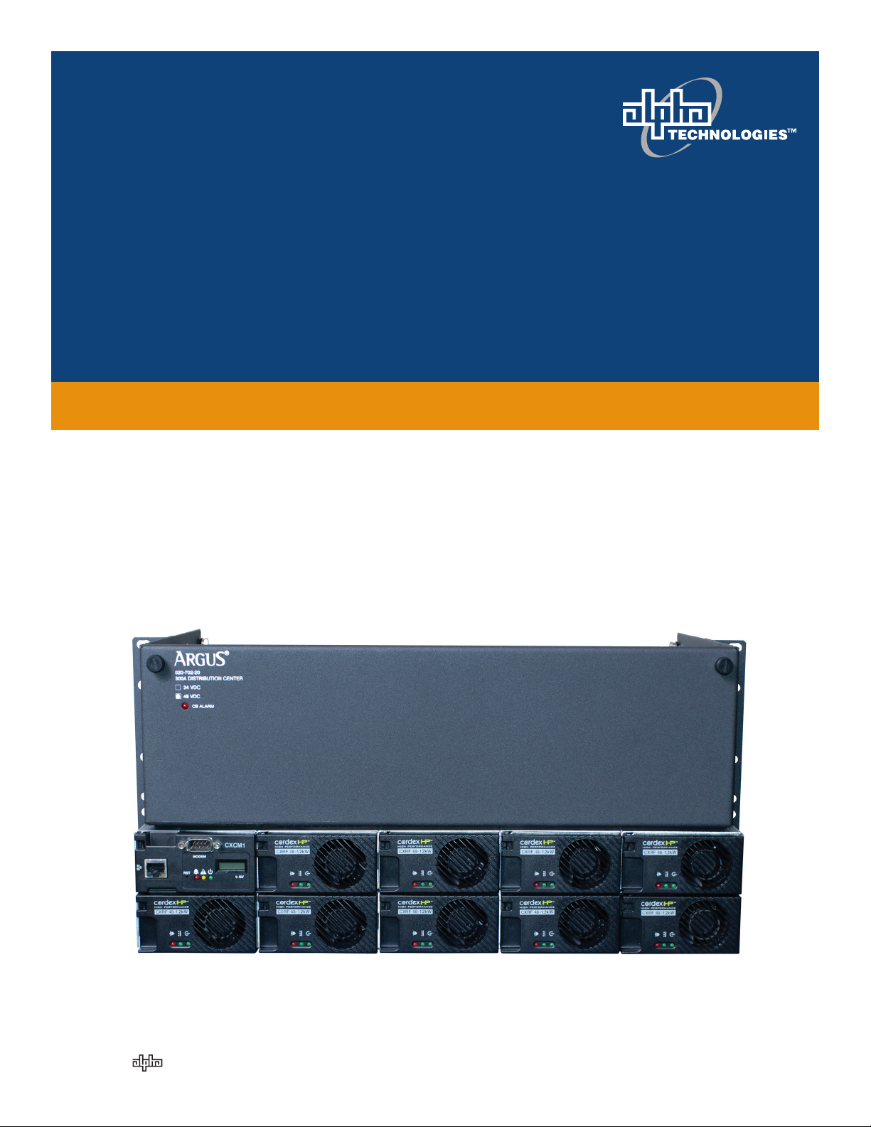
CXPS 48-1.2-225 48 Vdc Power System
Installation & Operation Manual
053-691-B1
Effective: 09/2012
member of The Group
™
Your Power Solutions Partner
Page 2

Page 3

CXPS 48 – 1.2-225 48Vdc Power System
053-691-B1
The following drawings are included in this manual:
• Schematic Drawing, CXPS 48-1.2-225_A 053-691-05
• Layout Drawing, CXPS 48-1.2-225_A 053-691-06
• Customer Connection, CXPS 48-1.2-225_A 053-691-08
Manuals to be included in this package:
• DCP03 300 A Distribution Center: 020-702-B2
• Cordex 48-1.2kW 19” 1 RU Shelf System 030-835-B2
• Cordex Controller Software (current version) CXC SOFT
Page 4

Page 5
IMPORTANT SAFETY INSTRUCTIONS
SAVE THESE INSTRUCTIONS
This section contains important instructions that must be followed during the installation and maintenance of the
equipment and batteries. Read all of the instructions before operating the equipment, and save this manual
for future reference.
All electrical connections must be performed by licensed electricians only. Installation of the power supply and
batteries must be performed by, or under the direct supervision of, service personnel knowledgeable of the
required electrical and battery safety procedures.
If instructions in this manual conflict with the local electrical codes, follow the local codes.
The following safety symbols are found throughout this manual. Carefully read all information and abide by the
instructions:
DANGEROUS VOLTAGE
This symbol indicates a dangerous voltage
exists in this area of the product.
GAS HAZARD
This symbol indicates a gas hazard
exists in the area of vented batteries.
NO MATCHES OR OPEN FLAMES
This symbol indicates a fire or explosive hazard
exists in the area of the product.
The following warning levels are used in conjunction with the symbols:
DANGER: You WILL be KILLED or SERIOUSLY INJURED if instructions are not followed closely.
WARNING: You CAN be KILLED or SERIOUSLY INJURED if instructions are not followed closely.
CAUTION: You CAN be INJURED or equipment can be DAMAGED if instructions are not followed closely.
Mechanical safety
Keep hands and tools clear of fans. Fans are thermostatically controlled and switch on automatically.
Power supplies can reach extreme temperatures under load.
Use caution around sheet metal components and sharp edges.
Page 6
Electrical safety
WARNING: Hazardous voltages are present at the input of power systems. The DC output from
rectifiers and batteries, though not dangerous in voltage, has a high short-circuit current capacity that
may cause severe burns and electrical arcing.
Before working with any live battery or power system, follow these precautions:
• Remove all metallic jewelry, such as watches, rings, metal rimmed glasses, or necklaces.
• Wear safety glasses with side shields at all times during installation.
• Use OSHA approved insulated hand tools.
DANGER: Lethal voltages are present within a power system. Always assume that an electrical
connection or conductor is energized. Check the circuit with a voltmeter with respect to the grounded
portion of the enclosure (both AC and DC) before performing any installation or removal procedure.
Do not work alone under hazardous conditions.
A licensed electrician is required to install permanently wired equipment. Input voltages can range up
to 240 Vac. Ensure that the utility power is disconnected and locked out performing any installation or
removal procedure.
Ensure that no liquids or wet clothes come into contact with internal components.
Hazardous electrically live parts inside this unit are energized from the batteries even when the AC input power is
disconnected.
Battery safety
Servicing and connection of batteries must be performed by, or under the direct supervision of, personnel
knowledgeable of batteries and the required safety precautions.
Always wear eye protection, rubber gloves, and a protective vest when working near batteries. Remove all
metallic objects from your hands and neck.
Use OSHA approved insulated hand tools. Do not rest tools on top of batteries.
Batteries contain or emit chemicals known to cause cancer and birth defects or other reproductive harm. Battery
post terminals and related accessories contain lead and lead compounds. Wash your hands after handling
batteries.
WARNING: Follow battery manufacturer’s safety recommendations when working around battery
systems.
WARNING: Do not smoke or introduce an open flame when batteries (especially vented batteries) are
charging. Batteries vent hydrogen gas when charging, which creates an explosion hazard.
Batteries are hazardous to the environment and should be disposed of safely at a recycling facility. Consult the
battery manufacturer for recommended local authorized recyclers.
Post installation weather proofing
After installing the conduits and removing any knockouts to accommodate conduit locations, ensure that any gaps
between the conduit fittings and the shroud are sealed. Apply a weatherproof caulking to gaps to prevent wind
driven rain from reaching the electrical equipment.
Page 7

TABLE OF CONTENTS
1 INTRODUCTION .................................................................................................................................................. 1
1.1 Manual scope ................................................................................................................................................ 1
1.2 Product overview .......................................................................................................................................... 1
1.3 Available system configurations ................................................................................................................... 2
1.4 Part numbers including options .................................................................................................................... 2
EATURES ......................................................................................................................................................... 4
2 F
2.1 System overview ........................................................................................................................................... 4
2.2 Distribution center ........................................................................................................................................ 4
2.3 CXCM1 Controller ......................................................................................................................................... 7
2.4 Rectifiers ..................................................................................................................................................... 10
2.5 Rectifier front panel .................................................................................................................................... 10
NSPECTION .................................................................................................................................................... 13
3 I
3.1 Packing materials ........................................................................................................................................ 13
3.2 Check for damage ....................................................................................................................................... 13
3.3 General receipt of shipment ....................................................................................................................... 13
NSTALLATION ................................................................................................................................................. 14
4 I
4.1 Safety precautions ...................................................................................................................................... 14
4.2 Tools required ............................................................................................................................................. 14
4.3 Power system assembly and mounting ...................................................................................................... 15
4.4 Rectifier module insertion/removal ........................................................................................................... 16
4.5 Breaker installation ..................................................................................................................................... 16
4.6 Breaker removal .......................................................................................................................................... 16
4.7 Battery installation ...................................................................................................................................... 17
IRING ......................................................................................................................................................... 19
5 W
5.1 Grounding ................................................................................................................................................... 19
5.2 AC feeder protection/sizing ........................................................................................................................ 19
5.3 AC input connections .................................................................................................................................. 19
5.4 Calculating output wire size requirements ................................................................................................. 20
5.5 DC output connections ............................................................................................................................... 20
5.6 System and battery connections ................................................................................................................ 20
5.7 Alarm connections ...................................................................................................................................... 22
5.8 CAN serial ports .......................................................................................................................................... 22
5.9 Network connection and remote communications via controller ............................................................. 23
5.10 Signal wiring connections for controller ..................................................................................................... 23
YSTEM STARTUP ............................................................................................................................................. 26
6 S
053-691-B1 Rev E Page i of ii
Page 8

6.1 Check system connections .......................................................................................................................... 26
6.2 Verify AC input and power up rectifier shelf .............................................................................................. 26
6.3 Check battery polarity and connect the batteries ...................................................................................... 26
6.4 Controller Reset .......................................................................................................................................... 27
6.5 LVD control ................................................................................................................................................. 27
PERATION .................................................................................................................................................... 28
7 O
7.1 Main rectifier states .................................................................................................................................... 28
7.2 Main rectifier modes................................................................................................................................... 29
7.3 Factory ranges and defaults ........................................................................................................................ 29
AINTENANCE ................................................................................................................................................ 31
8 M
8.1 General maintenance schedule .................................................................................................................. 31
8.2 Fan replacement ......................................................................................................................................... 31
ARRANTY .................................................................................................................................................... 32
9 W
9.1 Warranty ..................................................................................................................................................... 32
LPHA CONVENTIONS ....................................................................................................................................... 33
10 A
10.1 Acronyms .................................................................................................................................................... 33
FIGURES
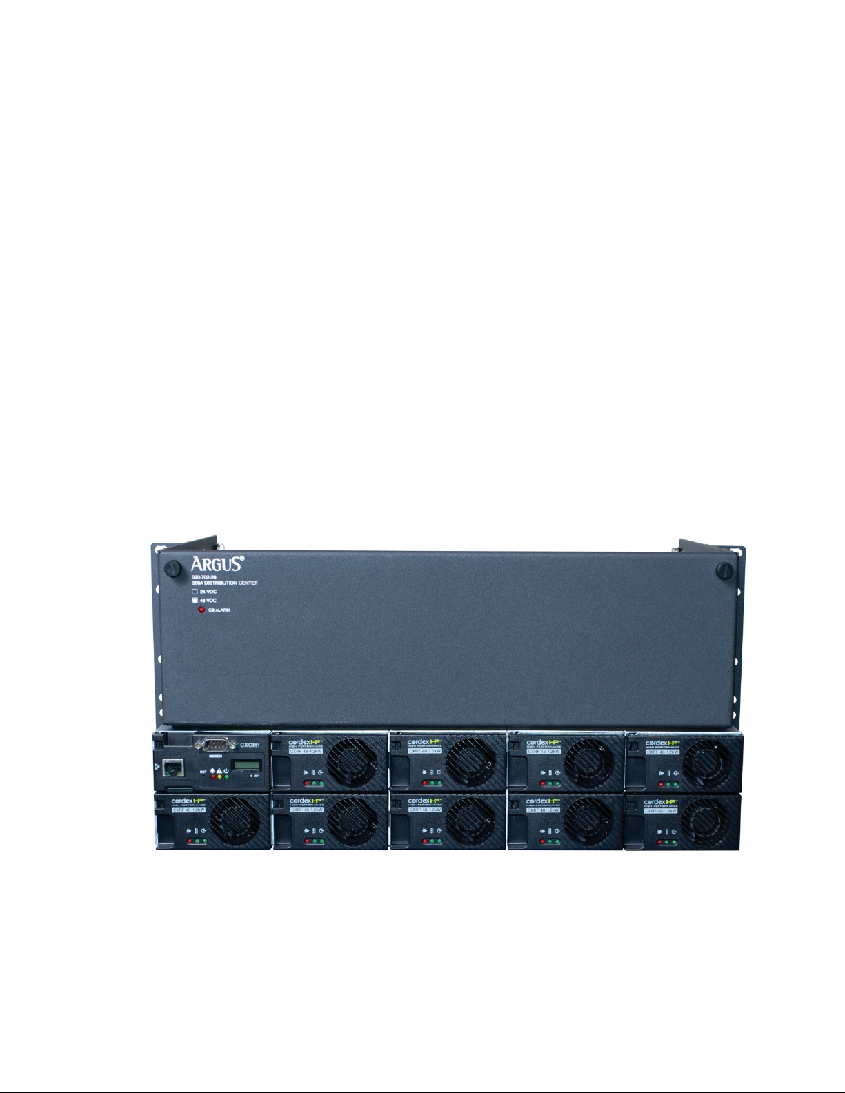
Figure 1–Front view of the 053-691-20-000 rail mount CXPS 48-1.2-225 configuration ................................................. 1
Figure 2–Distribution center configured for 4 battery and 14 load breakers .................................................................. 4
Figure 3–Internal alarm card ............................................................................................................................................ 5
Figure 4–Internal alarm card and controller I/O terminal block ...................................................................................... 6
Figure 5–4R/8D ADIO option ............................................................................................................................................ 6
Figure 6–Controller front panel ........................................................................................................................................ 7
Figure 7–Rectifier front panel ........................................................................................................................................ 10
Figure 8–Example of an insulated tool kit ...................................................................................................................... 14
Figure 9–Rear view of distribution panel ....................................................................................................................... 21
Figure 10–Battery, load, and return connection locations ............................................................................................ 21
Figure 11–DCP03 wire routing example ......................................................................................................................... 22
Figure 12–Showing relay connections ............................................................................................................................ 23
Figure 13–Showing digital input connection method .................................................................................................... 24
053-691-B1 Rev E Page ii of ii
Page 9
1 Introduction
1.1 Manual scope
This manual covers the features and installation of the Alpha Technologies CXPS 48-1.2-225 48V 225A Power
System.
1.2 Product overview
The CXPS 48-1.2-225 is a complete integrated 48 Vdc power system with 225 A capacity. The system uses the
advanced Cordex CXCM1 controller and HP 48 V 1.2 kW rectifier modules. The DCP03 300A distribution center
provides front access for DC distribution, site controller, and battery connections.
Cordex rectifier modules use a high frequency, switched mode conversion technique to provide a fully regulated
and isolated DC output from the AC mains. The rectifier input is wide range to allow use on
120/208/220/230/240/277 Vac 50/60 Hz electrical input. The system has de-rated output below 176 VAC input.
See specifications at the front of this manual.
The rectifier power modules are “hot swappable” meaning they can be inserted or removed from the shelf without
cutting power to or from the system or the load. Rectifier modules are not included with the base system, but may
be purchased along with the system at the time of ordering, or added after the shelf has been installed. The shelf
rectifier system is designed to operate with the Alpha Cordex CXCM1 controller.
This system uses the controller integrated version of the controller, which is factory installed on the Cordex
rectifier system shelf.
The CXC allows the user to configure, monitor and control the entire DC power system locally or remotely via a
web browser. Features of the unit include temperature compensation, auto equalization, remote access, e-mail
alarm notification, battery diagnostics, as well as web server and SNMP support for configuration and monitoring.
Details of the controller operation are provided in the software manual.
Figure 1–Front view of the 053-691-20-000 rail mount CXPS 48-1.2-225 configuration
053-691-B1 Rev E Page 1 of 33
Page 10

Description
Part Number
CXPS 48-1.2-225, Cordex base 48V 225A power system, 19/23" rail mount
053-691-20-000
CXPS 48-1.2-225 system installed in 7foot Z4 23" rack with 2x battery trays
053-691-20-040
CXPS 48-1.2-225 system installed in 7foot Z4 19" rack with 3x battery trays
053-691-20-031
Description
Part Number
Cordex HP 48-1.2kW rectifier power module
010-619-20-040
Breaker, AM-type mid-trip plug-in, 1 A
470-300-10
Breaker, AM-type mid-trip plug-in, 3 A
470-301-10
Breaker, AM-type mid-trip plug-in, 5 A
470-302-10
Breaker, AM-type mid-trip plug-in, 10 A
470-303-10
Breaker, AM-type mid-trip plug-in, 15 A
470-304-10
Breaker, AM-type mid-trip plug-in, 20 A
470-305-10
Breaker, AM-type mid-trip plug-in, 25 A
470-306-10
Breaker, AM-type mid-trip plug-in, 30 A
470-307-10
Breaker, AM-type mid-trip plug-in, 35 A
470-308-10
Breaker, AM-type mid-trip plug-in, 40 A
470-309-10
Breaker, AM-type mid-trip plug-in, 45 A
470-310-10
Breaker, AM-type mid-trip plug-in, 50 A
470-311-10
Breaker, AM-type mid-trip plug-in, 60 A
470-312-10
Breaker, AM-type mid-trip plug-in, 70 A
470-313-10
Breaker, AM-type mid-trip plug-in, 80 A
470-314-10
Breaker, AM-type mid-trip plug-in, 90 A
470-315-10
Breaker, AM-type mid-trip plug-in, 100 A
470-316-10
Load breaker kit, AM-type mid-trip plug-in, 125 A (2-pole)
747-523-20
Load breaker kit, AM-type mid-trip plug-in, 150 A (2-pole)
747-524-20
Load breaker kit, AM-type mid-trip plug-in, 175 A (3-pole)
747-525-20
Load breaker kit, AM-type mid-trip plug-in, 200 A (3-pole)
747-526-20
Load breaker kit, AM-type mid-trip plug-in, 250 A (3-pole)
747-527-20
Battery breaker, AM-type series-trip plug-in, 100 A
470-347-10
Battery breaker kit, AM-type series-trip plug-in, 150 A (2-pole)
747-503-20
Battery breaker kit, AM-type series-trip plug-in, 250 A (3-pole)
747-504-20
One universal AC line cord, C19R – flying leads, 3.5 m, feeds 2 modules
877-671-19
One 120Vac line cord, L5-15P plugs, 2.5 m, feeds 2 modules
877-690-19
Replacement rectifier blank plate
747-622-20-000
Replacement controller (basic module, 1RU horizontal mount)
018-598-20
23" battery tray expansion kit (for use with –040 configuration)
058-156-20
1.3 Available system configurations
The system is available to order in the following configurations:
1.4 Part numbers including options
This product is available to order with the following options and accessories:
053-691-B1 Rev E Page 2 of 33
Page 11

19" battery tray expansion kit (for use with –031 configuration)
058-157-20
Cordex DC Modem (complete with Alpha cable)
018-585-20
4R/8D ADIO expansion assembly
747-521-20
The above information is valid at the time of publication. Consult factory for up-to-date ordering information.
053-691-B1 Rev E Page 3 of 33
Page 12
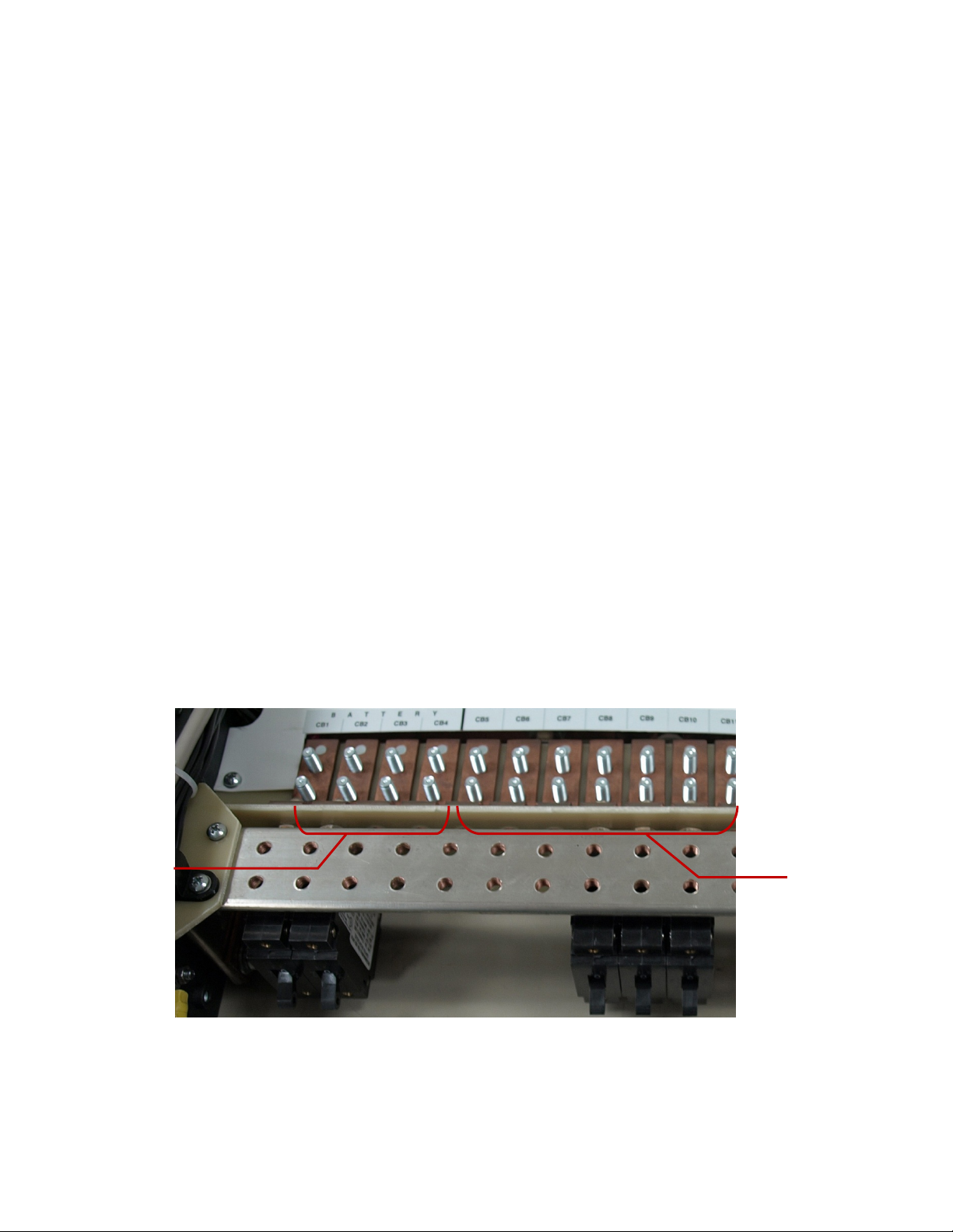
Load breaker
positions
Battery breaker
positions
2 Features
2.1 System overview
Basic configuration included in Alpha part number 053-691-20-000:
• 300A DCP03 distribution center
• Cordex modular system controller (CXCM1)
• Two (2) Cordex HP 48-1.2kW rectifier shelves (nine positions total)
• Kydex rear covers
• 19" rack mount rails with center and flush mount
• 19" to 23" rack mount adaptors
• System integration cabling and bus work
• Two (2) battery temperature compensation probes (12' each)
Rectifier modules, DC distribution breakers, and AC input cables are not included in the basic configuration. See
section 1.4 to order these optional components.
Optional configurations:
053-691-20-031: Basic configuration factory installed into a 7' x 19" Zone 4-relay rack and three (3) battery trays
with cabling and 100A battery disconnects for up to three (3) 48 V VRLA strings.
053-691-20-040: Basic configuration factory installed into a 7' x 23" Zone 4-relay rack and two (2) battery trays
with cabling and 100 A battery disconnects for up to two (2) 48 V VRLA strings.
2.2 Distribution center
2.2.1 Distribution configurations
The distribution center contains 18 AM-type plug-in breaker positions. Each breaker position has two-hole
connection points, one for the breaker output and another one for the ground return bus. The breaker distribution
system has 4 breaker positions for the batteries and 14 breaker positions for the loads.
053-691-B1 Rev E Page 4 of 33
Figure 2–Distribution center configured for 4 battery and 14 load breakers
Load breakers require mid-trip AM plug-in breakers while battery breakers require series-trip AM plug-in breakers.
If there is no power to the rectifiers and only one battery circuit breaker, there will be no alarm when the circuit
breaker trips.
Page 13
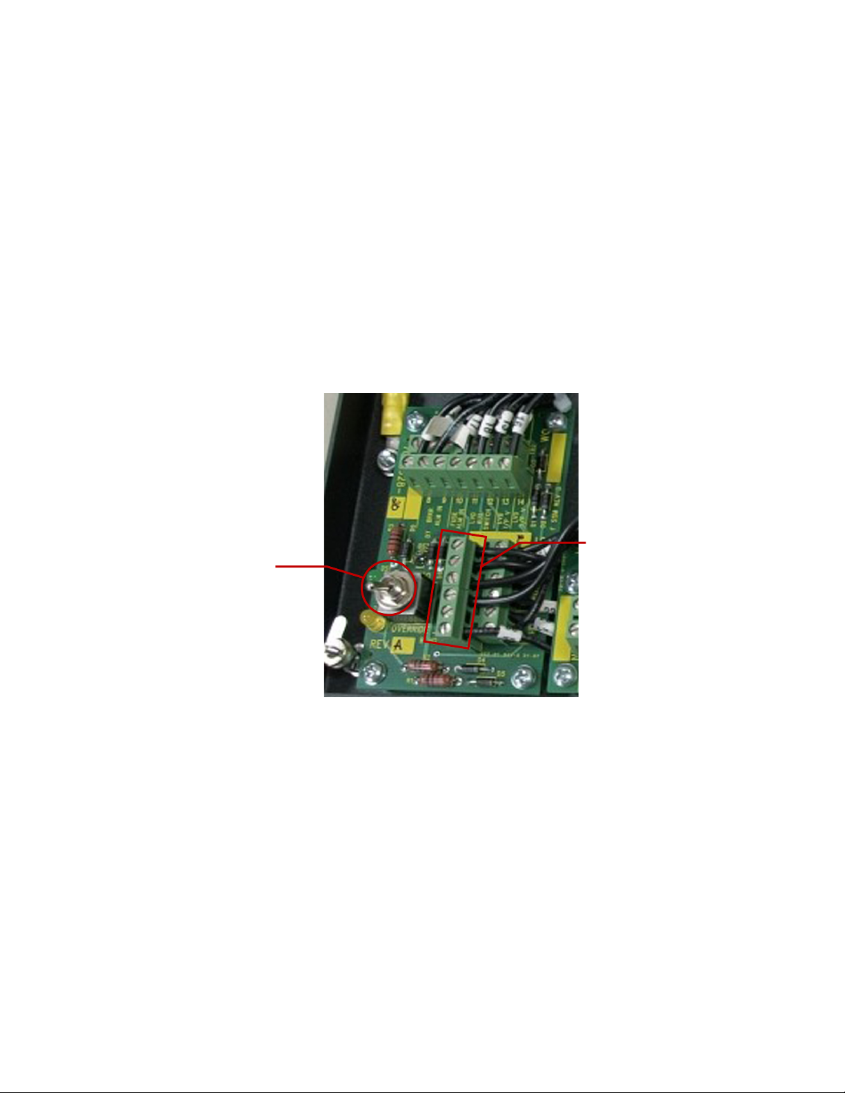
LVD override switch
I/O customer connection points
2.2.2 Low voltage battery disconnect (LVBD)
A low voltage disconnect (LVD) is installed in series with the batteries. This is called a low voltage battery
disconnect (LVBD).
2.2.3 Shunt
A shunt is installed in series with the batteries for current measurements. The controller automatically calculates
the load current.
2.2.4 Internal alarm card
The distribution center includes an alarm card, a low voltage disconnect override switch, and a breaker trip LED
indicator.
The alarm card provides terminal block access to internal signals such as binary alarms for breaker trips and
LVDs, alarm relays for driving the LVDs, and analog inputs for current (shunt) and voltage measurements. The
terminal block provides a single access point between these signals and an external system controller. Refer to
the customer connections (“–08”) drawing at the rear of this manual for details on terminal block assignments.
The LVD override switch allows the user to override the LVD during controller maintenance. A green LED
illuminates when the LVD is operating normally. A yellow LED illuminates when the LVD is in the override
position.
053-691-B1 Rev E Page 5 of 33
Figure 3–Internal alarm card
Page 14
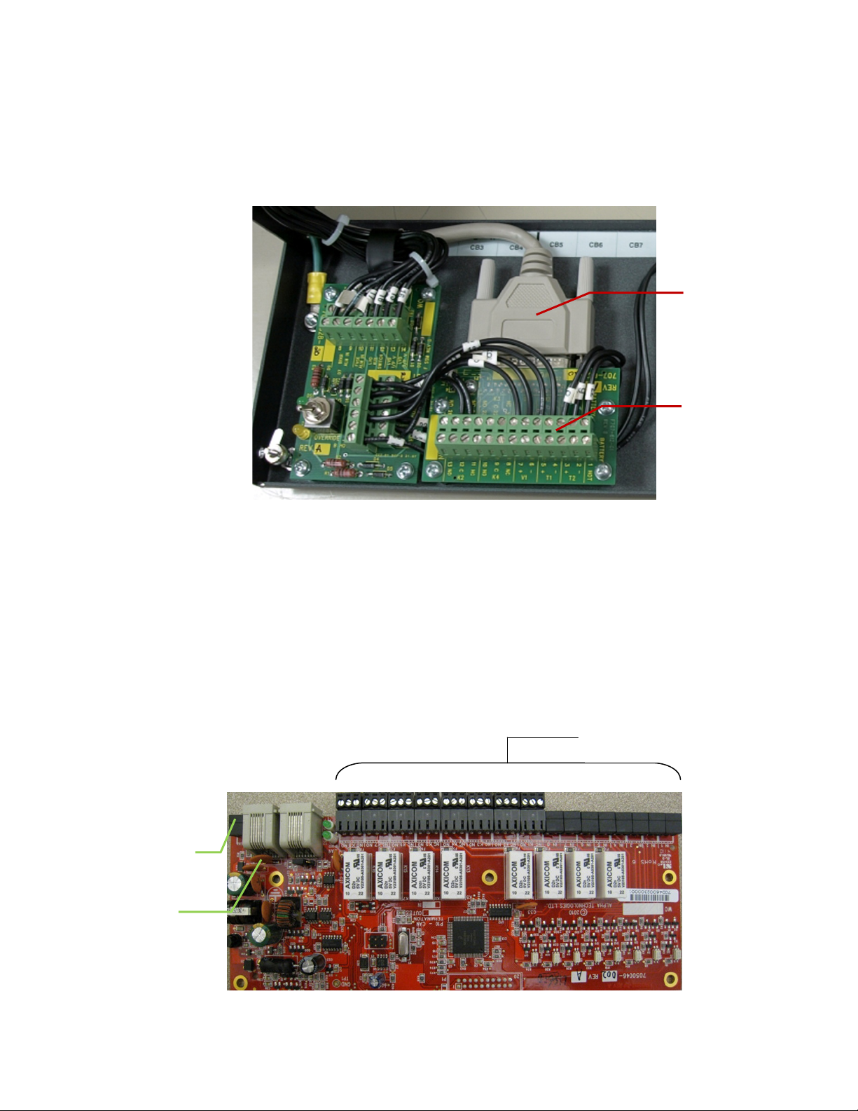
Controller I/O terminal
block assembly
D-sub wire harnesses to
1.8k W shelf
CAN in/out
8DIO power supply
Customer I/O
connections via
terminal blocks
2.2.5 Controller I/O terminal block
A controller I/O terminal block is installed in the distribution center front door to allow controller access to signals
and interfaces. A 25-pin D-sub wire harness is used to connect the terminal block to the controller.
The internal signals from the distribution center are wired to the controller I/O board directly from the internal
alarm board. The remaining relay outputs, digital inputs, and analog inputs can be accessed via terminal blocks to
customer connections. Refer to the customer connections (“–08”) drawing at the rear of this manual for details on
terminal block assignments.
2.2.6 8R/8D 8DIO (Option)
The 8R/8D 8DIO Cordex peripheral can be installed on the front door of the DCP03. The 8R/8D 8DIO option
expands the I/O capability of an existing Cordex controller by adding additional 8 relays outputs and 8 digital
inputs.
The 8R/8D 8DIO installs on the right side on the front door. The 8R/8D 8DIO is connected to the Cordex system
via CAN ports and RJ-12 offset communications cables.
All I/O connections are made via screw terminal blocks. Refer to the customer connections (“–08”) drawing at the
rear of this manual for details on terminal block assignments.
connection
Figure 4–Internal alarm card and controller I/O terminal block
053-691-B1 Rev E Page 6 of 33
Figure 5–8R/8D 8DIO option
Page 15
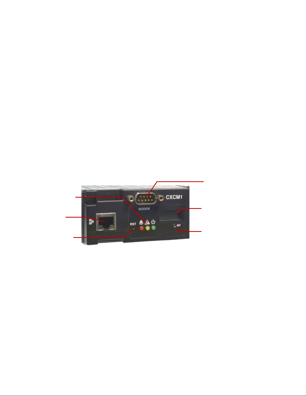
System status LEDs
Ethernet port
Push once for soft reset
Hold for 3 seconds
LCD screen (V/A)
Display pushbutton
toggle switch (V/A)
Modem port. Do not
connects to anything
other than an Alpha
modem and cable
2.3 CXCM1 Controller
Details of the controller operation are provided in the software manual.
The controller is mounted in the rectifier system shelf and controls the rectifiers. The controller includes software
that does the following:
• Direct communication with the rectifiers.
• Battery temperature compensation charging.
• Battery performance diagnostics.
• Local and remote communications.
• User definable alarms.
• Daily logging of power system events and system statistics.
The motherboard is located behind the controller’s front panel. The motherboard contains a microprocessor,
memory chips, and many other electronic components.
The controller includes a web server that provides easy set up and monitoring over an Internet connection to a
web browser.
The data-logging feature allows the user to automatically collect data from multiple sources. The collected data
can be AC/DC voltages, load/battery currents, cell voltages, and temperatures. Up to 16 user-defined logs are
available. Typical applications for the collected data include power system details, thermal performance of
outdoor enclosures, battery cell specifics, or power input variations captured by an AC voltage watchdog.
A built-in audio speaker sounds an intermittent tone during active alarms.
2.3.1 Controller front panel
2.3.2 LCD screen
The controller front panel uses a 4-digit LCD screen to monitor the system voltage (V) and current (A). A pushbutton toggle switch allows the user to alternate the display reading.
Figure 6–Controller front panel
053-691-B1 Rev E Page 7 of 33
Page 16
Illuminated
Green
OK, no alarms
Yellow
Minor alarm, no major alarms
Red
Major alarm
Illuminated
All three
Base unit validation
Red
File transfer
2.3.3 LED lights
Three LED lights are located on the front panel, one green, one yellow, and one red. The lights are used to
display the alarm status of the power system, controller progress and status during startup, and file transfers.
Alarm conditions
Only one LED light is illuminated at a time during alarm conditions. Each LED light corresponds to a specific
alarm.
Progress and status indication
The LED lights are also used in the following situations:
Alarm
LED
LED
2.3.4 Reset button
A reset button is located on the front panel for restarting the controller’s microprocessor. Select the reset menu
item before pressing the reset button. Refer to the software manual.
2.3.5 Modem port
A modem port is located on the front panel. It is designed to be used in conjunction with an Alpha DB-9 connector
and an Alpha Cordex DC Modem #018-585-20.
CAUTION: Connect the modem port with an Alpha-supplied modem and cable only. Otherwise,
equipment damage may result.
2.3.6 Ethernet port
An Ethernet port is located on the front panel. This port is designed to connect the controller to a user supplied
TCP/IP network. Use a standard RJ-45 jack with a standard network cable.
The Ethernet port can be used for local access, for example to a laptop computer. Use a standard network
crossover cable for the connection.
Situation
053-691-B1 Rev E Page 8 of 33
Page 17

2.3.7 Analog input channels
The controller is supplied with analog input channels for voltage, current, and temperature.
Voltage inputs
Two voltage input channels, V1 and V2, are used to monitor the discharge and charge voltage. The
controller software is pre-configured to monitor V1 for load voltage and V2 for battery voltage. V2, which is
wired internally, is used as a system reference for the rectifier float voltage, low voltage disconnect (LVD),
system high voltage alarm, and system low voltage alarm.
Current inputs
The controller software is pre-configured to monitor I1 for load current. It is wired internally to the system
current shunt.
Temperature inputs
Two temperature input channels, T1 and T2, provide monitoring of battery temperature and temperature
compensation (temp comp) or room/ambient temperature. Voltage is supplied to these terminals to power
the temperature sensors.
2.3.8 Digital input channels
The controller can accommodate up to two (2) digital input channels that can monitor digital alarm/control signals
from rectifiers, converters, and other types of equipment.
2.3.9 Alarm and control output relays
The controller contains four (4) Form C digital alarm output relays, which are used to extend alarms and control to
external apparatus. Each internally generated alarm or control signal may be mapped to any one of these relays,
or several signals may be mapped to just one relay or none at all.
2.3.10 Network connection and remote communications
The Cordex system can be set up, monitored, and tested via an Ethernet 10/100 Base-T serial data connection.
The communication protocol supports a web interface. A CAN bus is used to transmit all alarm and control
functions between the controller and rectifiers.
A step-by-step connection wizard is available. It installs a software package that provides remote communications
with your controller. It uses the Windows® 2000/XP operating system and is available at www.Alpha.ca
.
053-691-B1 Rev E Page 9 of 33
Page 18

2.4 Rectifiers
The rectifier modules employ an advanced resonant power conversion technology with high power conversion
efficiency. All internal semiconductor devices operate under “soft-switching” conditions and exhibit very low power
loss. The reduced power loss leads to lower thermal stresses on the semiconductors and thus improves reliability.
Sustaining low component temperatures is the primary factor with meeting three worst-case field scenarios: 65ºC
ambient temperatures, full output power, and low AC input (176 Vac). While meeting these specifications, Cordex
rectifiers are roughly twice as reliability at 55ºC ambient temperature and up to four times more at 45ºC.
2.5 Rectifier front panel
Figure 7–Rectifier front panel
2.5.1 LEDs
Three front panel LEDs are used to show the rectifier status and to help locate a specific rectifier module that is
under the control of the controller.
AC
The top green LED illuminates continuously when the AC input power is within the acceptable range and the
rectifier is delivering power to the load. It flashes when the AC input power is outside the acceptable range.
This happens when the AC Mains Low or AC Mains High alarms are activated. This LED light is off when
there is no AC input power.
DC
The middle green LED illuminates continuously when the rectifier is delivering power to the load. It flashes
when communication is lost. This LED light is off when the rectifier is off, for example when the rectifier is
switched off by the controller.
Alarm
The bottom red LED illuminates continuously during an active Module Fail alarm. It flashes when a minor
alarm is detected. This LED light is off when there are no alarms, no AC input power, or if the rectifier is not
connected to a battery or another parallel rectifier.
Locate Module command
When the Locate Module command has been received by the rectifier from the controller, the LEDs will flash
in a distinct pattern, repeating every 2 seconds.
Firmware upload
When a rectifier firmware upload is in progress, the LED pattern is the same as during the Locate Module
command.
2.5.2 Mechanical connections
A locking clip is used to secure the rectifier into the shelf. The rectifier must be locked into position during normal
operation. A handle or grip is incorporated into the front panel to help remove of the rectifier from the shelf. A 1/8"
x 4 flat head screwdriver is used to lift and release the clip from the locked position.
2.5.3 Rear panel
Connections for the shelf power and communications are located on the rear panel of the rectifier.
053-691-B1 Rev E Page 10 of 33
Page 19

2.5.4 True module fail alarm
The rectifier modules use a “true” fail alarm. This provides a true indication of the module’s ability to source
current. When a module’s output current drops below 2.5% of the rated output, a low output current condition is
detected and the Module Fail detection circuit is activated. This circuit momentarily ramps up the output voltage in
an attempt to increase the output current. If no increase in current is detected, the Module Fail alarm is activated.
When the Module Fail alarm is activated, the rectifier will check the output current once every 60 seconds until the
current is within the rated output. Output voltage ramping will then cease when the current reaches the rated
range. Under normal conditions, a battery that is connected to the rectifier output will draw current during a
voltage ramp up. A rectifier fail alarm will therefore not be generated when a battery is connected.
A minimum 2.5% load current is required to avoid a module fail alarm; but a bank of parallel batteries will typically
draw this much current. Activation of this alarm could indicate a failed rectifier module or a failed load.
To avoid nuisance alarms, disable the Ramp Test feature for rectifier systems without batteries or with a load;
below 2.5% of the rated output. Use the menu on the controller to enable/disable the Ramp Test. On the menu,
go to "Rectifiers", then "Configure Settings".
2.5.5 Heat dissipation
Each rectifier module is cooled by a variable-speed fan. The speed of the fan is governed by a temperature
sensor on the heat sink. The cooling air enters the front of the module and exits the rear of the module.
2.5.6 Over-temperature protection
Each rectifier module is protected against an excessive increase in temperature caused by a component failure or
blockage of the cooling air. During an over-temperature condition, the rectifier limits the output power and the
output current. If the temperature continues to increase, a shutdown of the rectifier is initiated. The rectifier
restarts automatically when the temperature returns to a safe level.
2.5.7 Wide AC input power range
A minor alarm is activated when the AC input voltage drops below a specified value. The output power is reduced
linearly between 176 Vac and 132 Vac to 60% of the rated output power. The input current is limited to less than
6 A for operation between 132 Vac and 90 Vac. A constant output power of 600 W is available between 132 Vac
and 112 Vac. The output power is derated linearly from 600W to ~475W @ 90Vac. At lower voltages, the module
will shut down and will not restart until the AC input voltage is greater than 90 Vac.
For input voltages above 277 Vac, the power factor and total harmonic distortion may be derated. The rectifier
may not work if the input voltage is above 320 Vac, but will not suffer any damage.
2.5.8 AC inrush/transient suppression
The inrush current into the rectifier module is limited to the full load steady state line current to prevent a current
surge on the AC input line. The modules are protected from input lightning and transient surges in accordance
with IEEE/ANSI C62.41 Category B3 standards.
053-691-B1 Rev E Page 11 of 33
Page 20

2.5.9 Soft start
A soft start feature, sometimes referred to as a “current walk-in”, is used to eliminate an instantaneous demand on
the AC input source. The soft start gradually ramps up the current limit from zero to the pre-determined setting
over a time interval of up to five seconds. The rectifier output voltage is ramped up from the minimum voltage to
the float voltage.
2.5.10 Start delay
The rectifier modules are equipped with a delay timer to sequentially start a series of modules to prevent
excessive generator loading during a start up. The controller can be used to set the time delay to between 1 and
120 seconds. The 1-second minimum delay allows the input capacitors to charge.
2.5.11 Current-limit/short circuit protection
The current-limit feature determines the maximum output current of the rectifier module, regardless of output
voltage or power. The maximum output current is limited to a constant value even during a short circuit. Current
limiting can be used to mate the rectifier output current ampacity to the needs of the load plus the batteries to
minimize excessive battery recharge currents.
The rectifier can sustain a short circuit at the output terminals indefinitely. The maximum short circuit current will
not exceed 105% of the rated full load current.
2.5.12 Power limiting
Each rectifier module is designed to limit the power output to a specified value. This enables more current to be
supplied at lower output voltages, and allows matching of output power to the demand of constant power loads,
which are often used in telecom equipment.
This feature may also be used for a faster recharge of flooded batteries that are connected in parallel with the
load. The current-limit function overrides the power-limit feature.
2.5.13 High voltage shutdown (HVSD)
The high voltage shutdown feature protects the load from over voltages originating from the rectifiers. It shuts the
offending rectifier module if its output voltage is above a preset limit. The red alarm (Module Fail) LED light
illuminates continuously. The rectifier will restart automatically once the overvoltage condition has passed.
However, if more than three over voltage conditions occur in one minute, the module will latch off and remain shut
down until it is reset via the controller.
2.5.14 Battery eliminator operation
A rectifier module maintains all its rated specifications (except where indicated) with or without a battery attached
in parallel with a load. However, if there is no battery or no other rectifier modules supplying DC voltages, there
will be no monitoring or control activity during an AC input power or input fuse failure.
053-691-B1 Rev E Page 12 of 33
Page 21

3 Inspection
3.1 Packing materials
All Alpha products are shipped in rugged, double-walled boxes and are suspended via solid inserts to minimize
shock that may occur during transportation. Packaging assemblies and methods are tested to International Safe
Transit Association standards. Power systems are custom packaged in heavy-duty plywood crates.
Products are also packaged with a plastic wrap that contains a corrosive-inhibitor that protects the product from
corrosion for up to two years.
Rectifiers and batteries are shipped on individual pallets and are packaged according to the manufacturer’s
guidelines.
3.1.1 Returns for service
Save the original shipping container. If the product needs to be returned for service, pack the unit in its original
shipping container. If the original container is unavailable, make sure that the product is packed with at least three
inches of shock-absorbing material to prevent shipping damage.
Alpha Technologies is not responsible for damage caused by the improper packaging of returned products.
3.2 Check for damage
Before unpacking the product, note any damage to the shipping container. Unpack the product and then inspect
the exterior for damage. Contact the carrier immediately if you see any damage.
Continue the inspection by checking for internal damage. In the unlikely event of internal damage, inform the
carrier and contact Alpha Technologies for advice on the impact of any damage.
3.3 General receipt of shipment
3.3.1 Racks
Consult the packing slip to verify that you have the correct number of racks that you ordered.
3.3.2 Rectifiers (purchased separately)
Consult the packing slip to verify that you have the correct number of rectifiers that you ordered.
3.3.3 Miscellaneous small parts
Review the packing slip to determine the part number of the “configuration kits” included with your system; e.g.,
053-691-20-040 for CXPS 48-1.2-225 system installed in 7' Z4 23" rack with 2x battery trays.
3.3.4 Batteries (purchased separately)
Refer to packing list to verify that you have the correct number of batteries.
Verify that you have all the necessary parts for proper assembly.
Call Alpha Technologies if you have any questions before you proceed: 1-888-462-7487
053-691-B1 Rev E Page 13 of 33
Page 22

4 Installation
Only qualified personnel should install and connect the power components within the Alpha power system. For
battery installation, refer primarily to the manufacturer’s manual. Refer to the drawings located at the rear of this
manual.
4.1 Safety precautions
Refer to the important safety instructions near the front of this manual.
4.2 Tools required
Appropriate insulated tools are essential for the installation. Use this list as a guide:
• Battery lifting apparatus.
• Electric drill with hammer action, ½" capacity
• Crimping tools and dies that match lugs used in the installation.
• Load bank of sufficient capacity to load the largest rectifier into current limit.
• Digital voltmeter with test leads
• Cable cutters.
• Torque wrench: ¼" drive, 0 - 150 in-lb.
• Torque wrench: 3/8" drive, 0 - 100 ft-lb.
• Insulating canvases (2' x 2', 1' x 1', 3' x 3', etc.)
• Insulated hand tools, see Figure 8:
-Combination wrenches -Ratchet and socket set
-Various screwdrivers -Electricians knife
• Battery safety spill kit required for wet cells:
-Protective clothing -Face shields
-Gloves -Baking soda
-Eye wash equipment
• Cutters and wire strippers 0.08 - 6 mm2 (#28 to #10 AWG).
Figure 8–Example of an insulated tool kit
053-691-B1 Rev E Page 14 of 33
Page 23

4.3 Power system assembly and mounting
The power system must be mounted in a clean and dry environment. Sufficient free space must be provided at
the front and rear of the power system. This is to meet the cooling requirements of the rectifiers and to allow easy
access to the power system components.
NOTE: The distribution center requires at least 1RU (1¾") of space above the unit to access to the load breaker ground
connections. Ensure that at least 1RU of space is open in the relay thread above the distribution center.
NOTE: The power system is suitable for installation in Network Telecommunication Facilities, locations where the NEC
applies, and OSP applications.
4.3.1 Rack mounted systems
Attach the power system to the customer-provided relay rack using thread-forming mounting screws and star
washers to ensure an electrical bond between the system chassis and relay rack.
The system may be mounted into a 19" rack in either a flush or center mount position. Use the 19"-to-23" rack
adaptors to mount into a 23" rack.
4.3.2 Floor mounted systems
Secure the system to a concrete floor by using heavy duty anchors (½" x 2½"). For wooden floors, use heavy-duty
lag screws (5/8" x 2½"). Use appropriately sized flat washers.
If required, use isolating kits to isolate the power system from the floor.
Secure the relay rack to the overhead cable tray. Alpha does not supply the mechanical parts needed for
overhead support.
053-691-B1 Rev E Page 15 of 33
Page 24

Module locking
clip at resting
position
Shelf tab
Turn screwdriver
approx. 30º gently
clockwise
locking clip
Insert ⅛" x 4 flat
head screwdriver
under locking clip
Controller removal
Rectifier removal
4.4 Rectifier module insertion/removal
Insert a rectifier module by placing the module on the bottom of the shelf and then sliding the module into the rear
connector inside of the shelf. Apply pressure on the front of the module to engage the rear connector in the shelf
receptacle. Use the enclosed locking clip to secure the rectifier into the shelf.
Insert the first module into the front leftmost position. Use the side of the shelf or the optional shelf-mounted
controller as a guide. Insert subsequent modules by using the previous module as a guide.
Do not force a module into position if it does not seat properly. All modules are keyed to ensure that the correct
module (voltage/polarity) type is used.
To remove a module, insert a ⅛" x 4 flat head screwdriver into the slot located on the top left corner of the front
plastic panel. With one hand, turn the screwdriver clockwise approximately 30º to move the clip from the resting
state (locked position). With the other hand, grasp the ledge of the finger opening on the front panel to pull the
module away from the rear connector and out of the shelf.
4.5 Breaker installation
1. Use trip breakers for load connections and series-trip breakers for battery connections.
2. Turn the breaker off.
3. Make sure that the breaker is right side up.
4. Align the breaker terminals with the correct holes.
5. Carefully push the breaker into position.
to raise
4.6 Breaker removal
1. Turn the breaker off.
053-691-B1 Rev E Page 16 of 33
2. Carefully pull the breaker out of its position.
Page 25

4.7 Battery installation
The battery installation procedure in this manual is a guideline only. The batteries are purchased separately from
the power system and have their own manuals.
WARNING Follow battery manufacturer’s safety recommendations when working around battery
systems and review the safety instructions provided in this manual.
4.7.1 Preparation/mounting
Batteries should be located in a temperature-controlled environment. Regulate the temperature to approximately
25°C (77°F). Significantly lower temperatures reduce the battery performance and higher temperatures decrease
life expectancy of the batteries.
Provide adequate ventilation. Although VRLA batteries do not require special ventilation systems like flooded
batteries, they should not be installed in an airtight enclosure. Hydrogen gas may emitted by a failed VRLA
battery.
If applicable, clean the cells according to the battery manufacturer's recommendations. First neutralize any acid
with a baking soda and water solution, and then rinse the cells with clean water.
4.7.2 Installation of batteries
Verify that all battery breakers, DC circuit breakers, and fuses on the distribution panels are either in
the OFF position or removed.
Use a corrosion-inhibiting agent, such as NO-OX-ID, on all battery terminal connections.
1. If applicable, assemble the battery rack and the cells or mono-blocks according the
installation instructions supplied with the batteries.
2. Make sure that the battery output cables are long enough to reach the [+] and [–]
terminals of the series battery string. Check that the batteries are oriented correctly
for easy installation of the inter-unit “series” connectors.
3. Remove any NO-OX-ID grease from battery terminals.
4. Burnish the terminal posts with a non-metallic brush, a polishing pad, or a 3M Scotch
Brite scouring pad.
5. Apply a light coating of NO-OX-ID grease to the terminal posts.
6. If lead plated inter-unit connectors are used, burnish them and apply NO-OX-ID as
above. Install the inter-unit connectors.
7. After all battery connections are completed, torque the bolts according to the battery
specifications, typically 100 in-lbs.
Refer to the system start-up procedure before connecting batteries online.
053-691-B1 Rev E Page 17 of 33
Page 26

Battery #
Serial #
Voltage
Specific
Ohms
Mhos
Observations
1 2 3
4
5 6 7 8 9
10
11
12
13
14
15
16
17
18
19
20
21
22
23
24
After assembly, number the batteries and take “as received” readings that include: specific gravity, cell voltage
and temperature. Designate one cell as the pilot cell. This is usually the cell with either the lowest specific gravity
or voltage. Refer to manufacturer's manual. See following table for a typical maintenance report:
Company: _______________________________________________________ Date: ________________________
Address: _____________________________________________________________________________________
Battery location and/or number: ___________________________________________________________________
No. of cells: __________________ Type: ______________________________ Date new: ____________________
Date installed: ________________ Float voltage: ________________________ Ambient temp.: ________________
Table A–Typical VRLA battery maintenance report (Cell readings)
053-691-B1 Rev E Page 18 of 33
Remarks and recommendations: __________________________________________________________________
____________________________________________________________________________________________
____________________________________________________________________________________________
Readings taken by: ________________________________________________
Page 27

Power system ampacity
Ground reference conductor size
< 30 A
#10
30 – 100 A
#6-2
100 – 400 A
0000
400 – 800 A
350 MCM
> 800 A
750 MCM
5 Wiring
This chapter provides cabling details and notes on cable sizing for DC applications.
WARNING Ensure that the power is removed by turning off rectifiers and removing battery line fuses
or connections before attempting work on the wiring connections. Use a voltmeter to verify the
absence of voltages. Clearly mark the correct polarity of the battery leads before working on DC
connections.
Refer to the Installation chapter for safety precautions and tools required.
5.1 Grounding
NOTE: This power system is suitable for installation as part of a Common Bonding Network (CBN) and is intended to be
used in a DC-C configuration (common DC return).
Connect the isolated power system battery return bus (BRB) to the building master ground bus (MGB) or floor
ground bus (FGB) in larger buildings. This acts as a system reference and a low impedance ground path for
surges, transients, noise, etc. The MGB or FGB should have a direct low impedance path to the building
grounding system.
Size the cable between the power system and the MGB or FGB so that there is sufficient ampacity to clear the
largest fuse or breaker on the power system, excluding the battery protection fuse or circuit breaker. This is the
minimum requirement. Other factors including length of cable and special grounding requirements of the load
must be factored in. The insulated cable should be equipped with two-hole crimp type lugs and should not have
any tight bends or kinks.
Table B–Typical ground reference conductor selection
5.1.1 Frame ground
The power system frame must also be connected to the MGB or FGB for safety reasons and to meet standard
Telco grounding requirements. Each bay must have its own frame or site ground connection. Refer to the
customer connections drawing at the rear of this manual.
2
The distribution center is grounded to the relay rack with screws/bonding washers, and then uses 35 mm
(#2 AWG) insulated cable to connect to the main grounding bus.
5.2 AC feeder protection/sizing
To maximize system reliability, each power module should be fed from a dedicated protection feeder breaker
located at the AC distribution panel. The feeder breaker can also be used as a disconnect device for the
connected module. Refer to the specifications at the front of this manual for Alpha recommendations.
5.3 AC input connections
CAUTION: AC input wires must be routed in flexible or rigid conduit as far away as possible from DC
power wires to minimize EMI disturbances.
Ensure that all modules are removed from the shelf. Refer to customer connections drawing. The shelf
incorporates IEC plug connections, which require line cords with C19R type receptacles. See ordering information
for available cords.
053-691-B1 Rev E Page 19 of 33
Page 28

5.4 Calculating output wire size requirements
To calculate wire sizes, first determine the appropriate maximum voltage drop requirement. Use the formula
below to calculate the CMA wire size requirement. Determine the size and number of conductors needed to
satisfy the CMA requirement.
CMA = (A x LF x K) / AVD, where:
CMA = Cross section of wire in circular MIL area
A = Ultimate drain in amps
LF = Conductor loop feet
K = 11.1 constant factor for commercial (TW type) copper wire
AVD = Allowable voltage drop
Check again that the ampacity rating of the cable meets the requirement for the installation application. Consult
local electrical codes (NEC, CEC, etc.) for guidelines. If required, increase the size of the cable to conform to the
code.
5.5 DC output connections
WARNING: Leave the cables or bus bars disconnected at the battery and verify the output polarity
using a voltmeter. Make the battery connections only after all other wiring is complete.
DC output wire must be UL approved XHHW or RHH/RHW (RW90 type for Canadian users). Control and sense
wires must be UL approved Style 1015 (TEW type for Canadian users).
Terminate the cable leads with appropriate crimp lugs.
Secure the positive and negative DC output cables to the shelf output post of the correct polarity; i.e., +Vcable to
+Vpost. Ensure that the washers are placed on the bolts in the same order in that they were shipped from the
factory.
Connect the common output leg of the rectifier system to the ground. This is typically done at the load common
termination point.
5.6 System and battery connections
WARNING: Ensure that the correct polarity is used for all cable terminations.
Refer to guidelines supplied with the load equipment. Distribution cables are typically sized to provide a 0.5 V loop
drop at full load and to meet ampacity requirements of the protection fuse or circuit breaker.
Size the battery cables for a 0.25 V drop from the battery to the power system at full load, including anticipated
additional loads. The cables must also meet ampacity requirements. Cables terminating directly on battery posts
or connection details must be secured so that there is no stress on the battery posts. To reduce corrosion, use
lead plated lugs and lead plated or stainless steel hardware on all terminations of vented batteries.
Prepare, route, and connect cables from the power system to the battery termination points. Burnish the
terminating points and apply a corrosion-inhibiting agent, such as NO-OX-ID, to all battery terminal connections.
Do not make the final connections to the live batteries. Switch off the battery contactors or remove the battery
fuses. See system startup procedure before connecting batteries online.
053-691-B1 Rev E Page 20 of 33
Page 29

Distribution
center input
(hot)
Load breaker (hot) connection
System return (ground) bar
Battery (hot)
Distribution
center input
(return) bar
5.6.1 DC input to panel
The distribution center contains a bus bar input for hot and return connections. The power system is configured
with vertical bus bars for rectifier shelf integration purposes. The bus bar inputs are fixed for hot and return
placement.
5.6.2 Distribution cabling
bar
Figure 9–Rear view of distribution panel
Refer to the guidelines supplied with the load equipment. Distribution cables are typically sized to provide a 0.5V
loop drop at full load as well as meeting ampacity requirements of the protection fuse or circuit breaker. Terminate
the distribution cables to the distribution center with ¼"–5/8"C lugs.
5.6.3 Breaker output (hot) connections
Connect the breaker output (hot) cables before connecting the breaker return (ground) cables. Secure the two
hole lugs to the ¼" studs (on 5/8" centers) using the hardware supplied with the distribution center. Run the
cables directly out of the rear of the distribution center. Refer to Figure 10.
5.6.4 Breaker return (ground) connections
Connect the breaker return (ground) cables o the distribution center ground bar. Secure the two hole lugs to the
¼" studs (on 5/8" centers) using the hardware supplied with the distribution center. Run the cables directly out of
the rear of the distribution center above the breaker output (hot) cables.
5.6.5 Battery breaker connections
Connect the battery breaker (hot) connections first using the same guidelines as the load cable installation.
Connect the battery ground cables using the same guidelines as the load return cables. The cables should run
directly out of the rear of the distribution center above the breaker output (hot) cables.
053-691-B1 Rev E Page 21 of 33
Figure 10–Battery, load, and return connection locations
Page 30

Cable clamp
System internal and
controller wire
4R/8D ADIO wire routing
4R/8D ADIO CAN ports
5.7 Alarm connections
Frequent reference is made to drawings located at the rear of this manual. Custom configurations are detailed
within the Alpha power system documentation package.
For terminal block connections, the recommended wire sizes are 0.14 - 1.50 mm
temperature range of 0 - 50ºC (UL/CSA).
CAUTION: to reduce risk of fire, use only 0.14 mm2 (#26 AWG) or larger wire.
Route the cables via wire-ways and use existing cable clamps to secure the existing (factory) wire harness and
the customer run signal wires. Route the signal wires along hinge points of the front door so that opening and
closing the door will not require excess wire slack. Refer to Figure 11 for a wire routing example.
Route the terminal block connections for the internal alarm card or controller I/O along the left side of the
distribution center (front view). Route the connections to the 4R/8D along the right hand side of the distribution
center. Refer to the customer connections (“–08”) drawing at the rear of this manual for details.
2
(#26 to #16 AWG) for a
5.8 CAN serial ports
5.8.1 CAN termination
053-691-B1 Rev E Page 22 of 33
Figure 11–DCP03 wire routing example
(Photo is for reference only – subject to installation requirements)
Two CAN serial ports are located on the side of the rectifier shelf. CAN serial ports are modular jacks with offset
latches that are used to communicate with the rectifiers and other CAN-enabled equipment (nodes) on the same
system. CAN serial ports are also found on the optional 4R/8D ADIO peripheral (Figure 11).
Daisy-chain the CAN serial ports from one node to the next (CAN OUT of one shelf to CAN IN of the next).
Ensure that only the last shelf is terminated as follows:
4-module shelf – termination IN – default
5-module shelf – termination OUT – default
This system has a limit of twelve 1.2 kW rectifiers. They do not have self-powered CAN bus nodes.
A CAN termination jumper is located beside the rightmost rectifier connector on the front of the shelf backplane.
See the customer connection drawing that describes your shelf.
Page 31

5.9 Network connection and remote communications via controller
The Cordex system can be set up, monitored and tested via an Ethernet 10/100 Base-T serial data connection.
The communication protocol supports a web interface. Pin-outs are shown in the customer connections drawing.
Some standard scenarios are described below:
5.9.1 Ethernet port for network connection (standard network cable)
The Ethernet port is designed to connect the controller to a user supplied network (TCP/IP supplied by the user)
via a front panel RJ-45 jack. Use a standard network cable for this connection.
5.9.2 Ethernet port for local connection (crossover cable)
The Ethernet port can be used for local access to for example a laptop computer. Use a standard network
crossover cable for this connection.
5.9.3 Controller modem port (Alpha cable)
The modem port on the front panel DB-9 connector (Figure 6) is designed for a controller connection to the Alpha
Technologies Cordex DC Modem #018-585-20. Use the Alpha-supplied cable for this connection.
CAUTION: Use only an Alpha-supplied modem and cable. Otherwise the equipment may be damaged.
5.10 Signal wiring connections for controller
Reference is made to drawings located at the rear of this manual. Custom configurations may be detailed within
the Alpha power system documentation package.
For terminal block connections, the recommended wire sizes are #16 - #26 AWG (1.5 - 0.129 mm
temperature range of 0 - 50ºC (as per UL/CSA).
CAUTION: To reduce risk of fire, use only #26 AWG (0.129 mmP
Bundle the signal cables together and route them through the entry holes of the shelf.
5.10.1 Alarm (relay) outputs
Terminals provide contacts for extending various alarm or control signals. Each relay output can be wired for NO
2
P
) or larger wire.
2
P
P
) for the
or NC operation during an alarm or control condition. See Figure 12.
Figure 12–Showing relay connections
Relays can be programmed to energize or de-energize during an alarm condition. See the controller software
manual. All relays will de-energize when the controller reset button is pressed or when the power is lost.
053-691-B1 Rev E Page 23 of 33
Page 32

Voltage level (VDC)
Voltage level (VDC)
0—60
5.10.2 Digital inputs for controller
The factory-installed digital input channels are used to monitor various alarm and control signals. All input
channels are voltage activated and directly accept a bipolar (negative or positive) DC signal.
D1 and D2 are available for customer connections.
Connection method
Typical Alpha systems use a “reset with Hot and trigger with Ground” connection. The digital input is wired so
that Hot is wired directly into one of the input terminals; e.g., negative input for -48 V systems. The other
input terminal is wired to the common ground of the system through a relay, which is a dry contact usually
located on the equipment that requires monitoring. This method allows the digital input to receive or not
receive a Ground signal during an alarm. See Figure 13.
Figure 13–Showing digital input connection method
Programming the digital input
The digital input channels can be programmed for “active high” or “active low.” Active high indicates an alarm
when a ground signal is present. Active low indicates an alarm when the ground signal is removed. See the
controller software manual.
Voltage range (VDC)
(system voltage setting)
considered 0 or off
considered 1 or on
0—3 18—60
Table C–Voltage level definitions for digital inputs
053-691-B1 Rev E Page 24 of 33
Page 33

5.10.3 Analog inputs
CAUTION: Ensure that the correct polarity is used for all input cable terminations.
The analog input channels are used to monitor various types of electrical signals. Some of the analog channels
are reserved for specific signals, while others are designated as general-purpose inputs that accommodate
various types of analog signals.
The Battery Hot input terminal on the I/O board is factory wired to the battery system terminal. This is done so that
the batteries will provide power to the controller when the main power circuit is disconnected from the batteries.
Voltage
The Voltage Input #1 (V1) terminal is located on the shelf to provide connections to an optional secondary
voltage input. For example, this input can be terminated to the load side of an LVD contactor to monitor the
load voltage.
The Voltage Input #2 (V2) is wired internally to the rectifier output voltage of the shelf. This input is used as a
reference for system alarms such as a high voltage, and for controls such as a low voltage disconnect.
Temperature sensor
The Temperature Probe input channels (T1 and T2) provide connections for temperature sensors. A voltage
is supplied to these terminals for sensor measurements.
Current
The Current Input #1 terminal (I1) is factory wired to the battery shunt.
053-691-B1 Rev E Page 25 of 33
Page 34

6 System startup
After completing the system installation and power system wiring, perform the following:
6.1 Check system connections
• Ensure that the AC input is switched off, the battery breaker is off, and all power modules are removed from
the shelf.
• Triple-check the polarity of all the connections.
6.2 Verify AC input and power up rectifier shelf
• Install one rectifier module.
• Verify that the AC input voltage is correct and switch on the corresponding feeder breaker.
• The controller OK LED light should illuminate continuously after a preset start delay.
• Using the controller, test the functionality of all module alarms and controls.
6.3 Check battery polarity and connect the batteries
• Verify the polarity of all the batteries with a voltmeter to ensure that no cells or batteries are reversed.
• Switch on the appropriate battery breaker.
• Install the remaining power modules.
• Use a web browser to access the adjustments menu of the controller. Set the float and equalize the voltage to
the levels specified by the battery manufacturer.
• Using the controller, test the functionality of various module alarms and controls. In addition, perform a load
test with the system using a resistive load box if needed.
• Enable the temperature compensation (Temp Comp) feature on the Batteries menu. Program the slope
setting and the upper and lower breakpoints according to the specific battery requirements.
6.3.1 Controller alarm Configuration for nominal 120 Vac operation
The default setting for the low AC input alarm is 180 Vac. For a nominal 120 Vac input, reset this value to
100 Vac.
To reconfigure this alarm parameter, go to “Alarms” and then “Configure Alarms”. Under “Alarm Configuration,”
select “Voltage Alarms.” Select and modify the activation value for “AC Mains Low” to 100 Vac. Submit the
changes to save the new configuration.
053-691-B1 Rev E Page 26 of 33
Page 35

6.4 Controller Reset
CAUTION: Before removing a controller from a live system or performing controller maintenance, an
external LVD inhibit or override is required to prevent a service disruption.
6.4.1 Soft reset
Use the reset button on the front panel of the optional controller is to restart the microprocessor. When pressed
momentarily, the unit beeps twice and then resets. The front-panel LED lights will illuminate temporarily and then
extinguish after the system has finished its 15-second self-test.
6.4.2 Controller IP address reset
To reset the IP address, press and hold the front panel reset button for three seconds. The controller unit will
beep three times, the IP will be reset (to 10.10.10.201), and DHCP will be disabled. The settings will be saved
and the unit will then reset.
This allows local access; e.g., to a laptop via a standard network crossover cable. See the software manual for
details.
6.4.3 Controller hard reset
There is a second reset button located to the right of the front panel on the side of the controller. This button is
used to restart the microprocessor if the front panel (soft) reset button does not work.
CAUTION: Use of the hard reset button may cause loss of data.
To access the hard reset button, remove the rectifier module adjacent to the controller.
6.4.4 Time setting
Upon startup, the controller will reset the time using the following sequence:
1) Attempt to synchronize with the NTP server (www.NTP.org).
2) Retrieve the last time stamp from the Event Log.
3) Retrieve the last time stamp from the Statistics Log.
4) Set the time to 2005-01-01 midnight.
6.5 LVD control
CAUTION: Before removing a controller from a live system or performing controller maintenance, an
external LVD inhibit or override is required to avoid a disruption of service.
The LVD Control functions are hardwired directly from the assigned relay output to an optional front panel LVD
override control. Place the LVD Control switch to the INHIBIT position to keep the LVD contactor engaged.
CAUTION Do not leave the switch in the INHIBIT position. Doing so may result in a complete discharge
of the batteries during a power failure situation.
To allow the controller to resume automatic control of the LVD contactor, check that the AUTO IN (green) LED
light is illuminated. This confirms that the controller will keep the LVD contactor engaged. The LVD control switch
can then be returned to the AUTO IN position.
Canada and USA toll free 24-hour emergency technical support: +1 888 GO ALPHA (462 7487).
053-691-B1 Rev E Page 27 of 33
Page 36

7 Operation
7.1 Main rectifier states
Rectifier operation can be broken up into five main states:
1. Off
2. Start Delay
3. Soft Start
4. Normal Operation
5. Turning Off
Each state is distinct and necessary for the operation of the rectifier. These states are briefly described below.
7.1.1 Off state
The rectifier is in the Off state immediately after power is applied to the rectifier or after a rectifier shutdown. The
shutdown source may be a remote or local shutdown, an AC shutdown, an over voltage shutdown, or a thermal
shutdown.
When the rectifier is in the Off state, the DC-DC converter is turned off. The controller monitors its inputs for the
proper conditions that allow the start-up sequence.
When the rectifier start-up conditions have been met, the rectifier will transition to the Start Delay state.
7.1.2 Start Delay state
When the rectifier is in the Start Delay state, the DC-DC converter is held off and not sourcing power, and waits
for a predetermined time before transitioning to the next state.
The controller continues to monitor its inputs during the Start Delay state.
After the Start Delay state, the rectifier will transition to the Soft Start state.
7.1.3 Soft Start state
When the rectifier is in the Soft Start state, the voltage and current output of the rectifier are gradually increased.
This is done to reduce the instantaneous load on the AC source. If a load is present, the rectifier begins to source
power.
When the voltage and current limits are reached, the rectifier will transition to the Normal Operation state.
7.1.4 Normal Operation state
During the Normal Operation state, the rectifier will be performing all of its specified rectifier functions.
From this state, the only valid transition is to the Turning Off state, which happens if the rectifier is required to shut
down.
7.1.5 Turning Off state
The Turning Off state consists of a short delay required to initialize some parameters before the rectifier actually
shuts off.
After the short delay, the rectifier transitions to the Off state.
053-691-B1 Rev E Page 28 of 33
Page 37

Output Voltage Modes
Active when…
Float
Output voltage is set to the float voltage setting.
Equalize
Output voltage is set to the equalize voltage setting.
Battery test
Output voltage is set to the battery test voltage setting.
Safe
Output voltage is set to the safe mode voltage setting.
Output Current/Power Mode
Active when…
Temperature foldback mode
Output current and power limit have been reduced because of high
AC foldback mode
Output current and power limit have been reduced because of low AC input
Short circuit foldback mode
Output current limit has been reduced because of a short circuit at the output.
Internal fault foldback mode
Output current limit has been reduced because of an internal fault.
Setting
Range (minimum to maximum)
Default
Float (FL) voltage
48 – 58 V
54 V
Equalize (EQ) voltage
50 – 58 V
55 V
Battery Test (BT) voltage
44 – 52 V
46 V
Safe mode voltage
46 – 56 V
51.4 V
OVP
59 V, cannot be set below present system FL/EQ/BT
57 V
Current limit (CL)
23 – 100%
100%
Power limit (PL)
0 – 100%
100%
Module start delay
0 – 250 s
1 s
System start delay
0 – 600 s
0 s
Low voltage alarm (LVA)
42 – 52 V
44 V
High voltage alarm (HVA)
52 – 59 V
55.5 V
7.2 Main rectifier modes
In addition to Main Rectifier States, there is a set of Main Rectifier Modes. These modes can be divided into two
categories as follows:
7.2.1 Output voltage modes
Voltage modes can be thought of as modes that, under software control, can directly adjust the output voltage.
There are processes that occur in the rectifier that can change the output voltage without software control, for
example when the rectifier is at the current limit. The following table lists the four output voltage modes and a
description of when they are active:
7.2.2 Output current/power modes
Table D–Output voltage modes
The output current/power modes directly affect the output current and power. The following table lists the four
output current/power modes and a description of when they are active:
7.3 Factory ranges and defaults
The following table lists the rectifier settings/ranges/defaults. Values can be adjusted via the controller:
temperature of the heat sink or internal ambient temperature sensor.
voltage. This reduces the risk of tripping an AC breaker because of increased
AC current draw as the AC voltage decreases.
Table E–Output current/power modes
053-691-B1 Rev E Page 29 of 33
Page 38

Setting
Range (minimum to maximum)
Default
EQ timeout
1 – 2399 h
30 h
BT timeout
1 – 250 h
8 h
Soft start ramp-rate
Normal/Fast
Normal
CL/PL alarm
Enable/Disable
Enable
Remote shutdown
Enable/Disable
Enable
Ramp test
Enable/Disable
Enable
Table F–CXPS 48-1.2-225 factory ranges and defaults
053-691-B1 Rev E Page 30 of 33
Page 39

Static electricity may damage circuit boards, including RAM chips. Always wear a grounded wrist
Description
Interval
Clean ventilation openings
1-6 months
Inspect all cable connections, re-torque if necessary
1 year
Verify alarm/control settings
1 year
Verify alarm relay operation
1 year
8 Maintenance
This equipment requires regular maintenance. The maintenance must be done by qualified service personnel
only.
WARNING: HIGH VOLTAGE AND SHOCK HAZARD Use extreme care when working inside the
enclosure/shelf while the system is energized. Do not make contact with live components or parts.
strap when handling or installing circuit boards. Ensure redundant modules or batteries are used to
eliminate the threat of service interruptions while performing maintenance on the system’s alarms
and control settings.
8.1 General maintenance schedule
8.2 Fan replacement
1. Shut off the unit and unlock the power module.
2. Slide the module 10 cm (4") out of the shelf and wait two minutes for the module capacitors to discharge.
3. Remove the bottom screw that secures the front panel to the module chassis.
4. Slide out the front panel.
5. Disconnect the fan power wires from the module.
6. Note the direction of the airflow and remove the fan from the front panel.
7. Install the replacement fan following the preceding steps in reverse order.
053-691-B1 Rev E Page 31 of 33
Page 40

9 Warranty
Visit http://www.alpha.ca/web2/services-and-support/warranty.html for full warranty information.
9.1 Warranty
Alpha Technologies Ltd. warrants all equipment manufactured by it to be free from defects in parts and labor, for
a period of two years from the date of shipment from the factory. The warranty provides for repairing, replacing or
issuing credit (at Alpha’s discretion) for any equipment manufactured by it and returned by the customer to the
factory or other authorized location during the warranty period. There are limitations to this warranty coverage.
The warranty does not provide to the customer or other parties any remedies other than the above. It does not
provide coverage for any loss of profits, loss of use, costs for removal or installation of defective equipment,
damages or consequential damages based upon equipment failure during or after the warranty period. No other
obligations are expressed or implied. Warranty also does not cover damage or equipment failure due to cause(s)
external to the unit including, but not limited to, environmental conditions, water damage, power surges or any
other external influence.
The customer is responsible for all shipping and handling charges. Where products are covered under warranty
Alpha will pay the cost of shipping the repaired or replacement unit back to the customer.
053-691-B1 Rev E Page 32 of 33
Page 41

Acronym
Definition
AC
Alternating current
ANSI
American National Standards Institute
AWG
American wire gauge
BTU
British thermal unit
CAN
Controller area network
CEC
Canadian Electrical Code
CMA
Circular mil area
CSA
Canadian Standards Association
CX
Cordex™ series; e.g., CXC for Cordex System Controller
DC
Ground fault circuit interrupter
DCP
Distribution center plug-in
EMC
Electromagnetic compatibility
EMI
Electromagnetic interference
ERM
Electromagnetic compatibility and radio spectrum matters
ESD
Electrostatic Discharge
FCC
Federal Communications Commission (for the USA)
HVSD
High voltage shutdown
IEC
International Electrotechnical Commission
IEEE
Institute of Electrical and Electronics Engineers
IP
Internet Protocol
LED
Light emitting diode
LVD
Low voltage disconnect
LVBD
Low voltage battery disconnect
LVLD
Low voltage load disconnect
MIL
One thousandth of an inch; used in expressing wire cross sectional area
MOV
Metal oxide varistor
MTBF
Mean time between failures
NC
Normally closed
NEC
National Electrical Code (for the USA)
NO
Normally open
OSHA
Occupational Safety & Health Administration
OVP
Over voltage protection
RAM
Random access memory
RU
Rack unit (1.75”)
TCP/IP
Transmission control protocol / internet protocol
UL
Underwriters Laboratories
VRLA
Valve regulated lead acid
10 Alpha Conventions
10.1 Acronyms
053-691-B1 Rev E Page 33 of 33
Page 42

BREAKER OUTPUTS
BREAKER RETURNS
1/4-20 HARDWARE
ON 5/8" CENTERS
1/4-20 HARDWARE
ON 5/8" CENTERS
CHASSIS GROUND
#10-32 STUD, BOTH SIDES
A
A
SITE GROUND CABLE CONNECTION
3/8-16 HARDWARE ON 1" CENTERS
020-702-20
REV.
CORRECT POLARITY LABEL;
SWAP RECTIFIER SHELVES;
A
UPDATE TEMPLATE; REFER
TO ECO-10718
DESCRIPTION
REVISIONS
3/22/2011
DATE
DRWN
HW
CHKED
ME ME
APPR'D
030-835-20
A
030-845-20
AC INPUT LINE CORDS
2 PL
AC INPUT LINE CORDS
3 PL
NOTE: AC LINE CORDS NOT INCLUDED
WITH POWER SYSTEM
018-598-20 (CXCM1 CONTROLLER)
010-619-20 (CXRF 48-1.2kW RECTIFIER)
UPTO 9 RECTIFIERS MAX.
UNLESS OTHERWISE SPECIFIED
DIM ARE IN INCHES [mm].
X.X [X]
X.XX [X.X]
X.XXX [X.XX]
ANGULAR:
INTERPRET DIM AND TOL PER
THIRD ANGLE PROJECTION
0.040
0.020
0.010
1
ASME Y14.5M-1994
[
1]
[
0.5]
0.25]
[
THESE DESIGNS AND SPECIFICATIONS ARE
CONFIDENTIAL, REMAIN THE PROPERTY OF
ALPHA TECHNOLOGIES LTD., AND SHALL NOT BE
COPIED OR USED WITHOUT ITS WRITTEN CONSENT
WH
MC
DATE
2009-09
SY
SY
2009-09
2009-10
2009-10
APPROVALS
DRAWN
CHECKED
DESIGN
APPROVED
ISSUE DATE
TITLE:
CUSTOMER CONNECTION,
CXPS 48-1.2-225 A
SIZE
SCALE 1:1
DWG NO.
TYPE
B
D2
053-691-08
SHEET
REV
A
1OF2
Page 43

LVD OVERRIDE
SWTICH
GREEN LVD AUTO
CONTROL LED
USED INTERNALLY
020-702-20 PCB DETAILS
EXTERNAL VOLTAGE
SIGNAL INPUT
(3) FORM C RELAY ALARM
CUSTOMER CONNECTIONS
(NOTE: ALL OTHER INPUTS
USED INTERNALLY)
YELLOW LVD
OVERRIDE LED
LIST 2 - LVD OVERRIDE / DISTRIBUTION ALARM PCB
USED INTERNALLY
LIST 74 - CXCI / CXCM1 INTERFACE PCB
CAN TERMINATION SETTINGS
CAN
TERMINATION
CLOSE
CAN
TERMINATION
CAN
TERMINATION
OPEN
OPEN
UNLESS OTHERWISE SPECIFIED
DIM ARE IN INCHES [mm].
X.X [X]
X.XX [X.X]
X.XXX [X.XX]
ANGULAR:
INTERPRET DIM AND TOL PER
THIRD ANGLE PROJECTION
0.040
0.020
0.010
1
ASME Y14.5M-1994
[
1]
[
0.5]
0.25]
[
THESE DESIGNS AND SPECIFICATIONS ARE
CONFIDENTIAL, REMAIN THE PROPERTY OF
ALPHA TECHNOLOGIES LTD., AND SHALL NOT BE
COPIED OR USED WITHOUT ITS WRITTEN CONSENT
WH
MC
DATE
2009-09
SY
SY
2009-09
2009-10
2009-10
APPROVALS
DRAWN
CHECKED
DESIGN
APPROVED
ISSUE DATE
TITLE:
CUSTOMER CONNECTION,
CXPS 48-1.2-225 A
SIZE
SCALE 1:1
DWG NO.
TYPE
B
D2
053-691-08
SHEET
REV
A
2OF2
Page 44

221.7
215.6
183.9
171.2
139.4
126.7
95.0 3.74
82.3 3.24
50.5 1.99
37.8 1.49
8.73
8.49
7.24
6.74
5.49
4.99
589.8 23.22
482.6 19.00
REV.
A
DESCRIPTION
CORRECT POLARITY LABELS;
SWAP RECTIFIER SHELVES;
UPDATE TEMPLATE; REFER
TO ECO-10718
REVISIONS
3/22/2011
DATE
DRWN
HW
CHKED
ME ME
APPR'D
6.1 0.24
0
614-858-W3 19" - 23"
CENTER MOUNT ADAPTER
126.7
465.0
566.7
18.31
22.31
19" RACK
23" RACK
16.8 0.66
CENTER MOUNT
5.0
376.4
14.8
A
A
614-858-W3 19" - 23"
CENTER MOUNT ADAPTER
UNLESS OTHERWISE SPECIFIED
DIM ARE IN INCHES [mm].
X.X [X]
X.XX [X.X]
X.XXX [X.XX]
ANGULAR:
INTERPRET DIM AND TOL PER
THIRD ANGLE PROJECTION
0.040
0.020
0.010
1
ASME Y14.5M-1994
[
1]
[
0.5]
0.25]
[
THESE DESIGNS AND SPECIFICATIONS ARE
CONFIDENTIAL, REMAIN THE PROPERTY OF
ALPHA TECHNOLOGIES LTD., AND SHALL NOT BE
COPIED OR USED WITHOUT ITS WRITTEN CONSENT
WH
MC
DATE
2009-09
SY
SY
2009-09
2009-10
2009-10
APPROVALS
DRAWN
CHECKED
DESIGN
APPROVED
ISSUE DATE
TITLE:
OUTLINE DRAWING, ASSM,
CXPS 48-1.2-225 A
SIZE
SCALE 1:1
DWG NO.
TYPE
B
D2
053-691-06
SHEET
REV
A
1OF3
Page 45

2133.6 84.00
235.2
FOR 5 RU
9.26
457.2 18.00
304.8 12.00
304.8 12.00
457.2 18.00
SYSTEM INSTALLED IN 19", 7ft Z4 RACK
CXPS 48-1.2-225_A
WITH 3 x BATTERY TRAYS
(PRE-WIRED FOR 3 x 48V VRLA STRINGS)
053-691-20-031 SHOWN
286.3 11.27
547.7 21.56
400.6 15.77
317.5 12.50
355.6 14.00
8RU TYP
23.8
203.2
8.00
0.94
TYP
UNLESS OTHERWISE SPECIFIED
DIM ARE IN INCHES [mm].
X.X [X]
X.XX [X.X]
X.XXX [X.XX]
ANGULAR:
INTERPRET DIM AND TOL PER
THIRD ANGLE PROJECTION
0.040
0.020
0.010
1
ASME Y14.5M-1994
[
1]
[
0.5]
0.25]
[
467.2 18.39
THESE DESIGNS AND SPECIFICATIONS ARE
CONFIDENTIAL, REMAIN THE PROPERTY OF
ALPHA TECHNOLOGIES LTD., AND SHALL NOT BE
COPIED OR USED WITHOUT ITS WRITTEN CONSENT
WH
MC
DATE
2009-09
SY
SY
2009-09
2009-10
2009-10
APPROVALS
DRAWN
CHECKED
DESIGN
APPROVED
ISSUE DATE
304.8 12.00
TITLE:
OUTLINE DRAWING, ASSM,
CXPS 48-1.2-225 A
SIZE
SCALE 1:1
DWG NO.
TYPE
B
D2
053-691-06
SHEET
REV
A
2OF3
Page 46

2133.6 84.00
235.2
FOR 5 RU
9.26
SYSTEM INSTALLED IN 23", 7ft Z4 RACK
WITH 2 x BATTERY TRAYS
(PRE-WIRED FOR 2 x 48V VRLA STRINGS)
053-691-20-040 SHOWN
CXPS 48-1.2-225_A
286.3 11.27
649.3 25.56
502.2 19.77
419.1 16.50
400.1 15.75
9 RU TYP
23.8
203.2
8.00
0.94
TYP
UNLESS OTHERWISE SPECIFIED
DIM ARE IN INCHES [mm].
X.X [X]
X.XX [X.X]
X.XXX [X.XX]
ANGULAR:
INTERPRET DIM AND TOL PER
THIRD ANGLE PROJECTION
0.040
0.020
0.010
1
ASME Y14.5M-1994
[
1]
[
0.5]
0.25]
[
585.9 23.07
THESE DESIGNS AND SPECIFICATIONS ARE
CONFIDENTIAL, REMAIN THE PROPERTY OF
ALPHA TECHNOLOGIES LTD., AND SHALL NOT BE
COPIED OR USED WITHOUT ITS WRITTEN CONSENT
WH
MC
DATE
2009-09
SY
SY
2009-09
2009-10
2009-10
APPROVALS
DRAWN
CHECKED
DESIGN
APPROVED
ISSUE DATE
TITLE:
OUTLINE DRAWING, ASSM,
CXPS 48-1.2-225 A
SIZE
SCALE 1:1
DWG NO.
TYPE
B
D2
053-691-06
SHEET
REV
A
3OF3
Page 47

Page 48

Page 49

Page 50

Page 51

Page 52

Alpha Technologies Ltd.
7700 Riverfront Gate
Burnaby, BC V5J 5M4
Canada
Tel: +1 604 436 5900
Fax: +1 604 436 1233
Toll Free: +1 800 667 8743
Alpha Energy,
Alpha Technologies Inc.
3767 Alpha Way
Bellingham, WA 98226
United States
Tel: +1 360 647 2360
Fax: +1 360 671 4936
Alpha Industrial Power Inc.
1075 Satellite Blvd NW,
Suite 400
Suwanee, GA 30024
United States
Tel: +1 678 475 3995
Fax: +1 678 584 9259
Outback Power
5917 195th St NE,
Arlington, WA 98223
United States
Tel: +1 360 435 6030
Fax: +1 360 435 6019
Alpha Technologies Europe Ltd.
Twyford House Thorley
Bishop’s Stortford
Hertfordshire, CM22 7PA
United Kingdom
Tel: +44 1279 501110
Fax: +44 1279 659870
Alpha Technologies
Suite 1903, 191F., Tower 1,
33 Canton Rd. Tsim Sha Tsui
China, Hong Kong City,
Kowloon, Hong Kong
Tel: +852 2736 8663
Fax: +852 2199 7988
Alpha Technologies GmbH
Hansastrasse 8
D-91126
Schwabach, Germany
Tel: +49 9122 79889 0
Fax: +49 9122 79889 21
Alphatec Ltd.
339 St. Andrews St.
Suite 101 Andrea Chambers
P.O. Box 56468
3307 Limassol, Cyprus
Tel: +357 25 375 675
Fax: +357 25 359 595
Alpha Innovations Brasil
Rua Manuel Augusto
de Alvarenga, 155
São Paulo, SP - Brasil
Tel: +55 11 2476 0150
Fax: +55 11 2476 0150
For technical support, contact Alpha Technologies:
Canada and USA: 1-888-462-7487
International: +1-604-436-5547
Alpha Technologies S.A.
131 Boulevard de l’Europe
1301 Wavre
Belgium
Tel: +32 10 438 510
Fax: +32 10 438 213
Alpha TEK ooo
Khokhlovskiy Pereulok 16
Stroenie 1, Office 403
Moscow, 109028
Russia
Tel: +7 495 916 1854
Fax: +7 495 916 1349
Alphatec Baltic
S. Konarskio Street 49-201
Vilnius, LT-03123
Lithuania
Tel: +370 5 210 5291
Fax: +370 5 210 5292
Visit us at www.alpha.ca
Due to continuing product development, Alpha Technologies reserves the right to change specifications without notice.
Copyright © 2012 Alpha Technologies. All Rights Reserved. Alpha® is a registered trademark of Alpha Technologies.
 Loading...