

Page 1
Cordex 125-4.4kW
Modular Switched Mode Rectifier
010-589-B2
Page 2

This page intentionally left blank.
Argus Technologies Ltd. Visit www.argus.ca
Burnaby, British Columbia. Telephone: 604 436 5900 Fax: 604 436 1233
Argus Technologies reserves the right to make changes to the products and information contained in this document without notice.
Copyright 2008 Argus Technologies Ltd. Argus
Printed in Canada.
®
is a registered trademark of Argus Technologies Ltd. All Rights Reserved.
Page 3

Cordex 125-4.4kW
Modular Switched Mode Rectifier
010-589-B2
The following documents and drawings are included in this manual to provide the necessa ry information required for
installation, operation and fault diagnosis of the unit:
• Specifications, Cordex 125-4.4kW: 010-589-B1 Rev A
• Warranty Policy: 048-507-10
• CSA/NRTL Equivalence: 048-554-10
• Installation and Operation Instructions: 010-589-C0 Rev A
• Outline Drawing, 19” Shelf: 030-769-06
• Customer Connections, 19” Shelf: 030-769-08
• Spare Parts List: 010-589-G0
• Factory Service Information: 048-527-10
Argus Technologies Ltd. 010-589-B2 Rev A WC
Printed in Canada. © 2007 Argus Technologies Ltd. ARGUS and CORDEX are trademarks of Argus Technologies Ltd. All Rights Reserved.
Page 4

MANUAL ADDENDUM
Unit Description: Cordex 125-4.4kW Modular Switched Mode Rectifier
Manual P/N: 010-589-B2 Applies to Manual Revision: A
# Date Page# Line# Correction to be implemented
1 07-11-20 7
of 010-589-C0
37 Add text to Section 5.5:
WARNING
Use care when removing or replacing the covers for the AC input
connections. Never assume that an electrical connection or
conductor is not energized.
MANUAL ADDENDUM
Authorized by: FORM 954-010-10 010589b2a1_addendum_coverplates.doc
Page 5

Specifications for Argus’ Switched Mode Rectifier Cordex 125-4.4kW
Power Module Output
Voltage: 90 to 160Vdc within rated limits
Current: 35.2A @ 125Vdc nominal (40A @ 110Vdc maximum)
Maximum Power: 4400W continuous/module
Static Load Regulation: Better than ±0.5% for any load change within rated limits
Dynamic Load Regulation: Better than ±5% for 40% - 90 - 40% step load change at nominal output voltage
(output shall recover to static limits within 30ms)
Static Line Regulation: Better than ±0.1% for any change in input voltage within rated limits
Dynamic Line Regulation: Better than ±1% for any change in input voltage within rated limits
(output shall recover to static limits within 10ms)
Hold-up Time: >10ms
Time Stability: ≤0.5% per year
Temperature Stability: <100ppm/°C over the operating range
Heat Dissipation: <1080 BTU per hour
Electrical Noise: <90mVrms 10kHz to 10MHz (wideband)
<700mVp-p 10kHz to 100MHz
Acoustic Noise: <55dBa @ 1m (3ft.) A weighted @ 30°C (86°F) [five modules in a shelf]
EMI: The unit meets requirements of EN55022 (see Standards for more EMC)
In accordance with FCC requirements, we provide the following statement as specified in the FCC guidelines for
conformance to Part 15, Class A:
NOTE: This equipment has been tested and found to comply with the limits for a Class A digital
device, pursuant to part 15 of the FCC Rules. These limits are designed to provide reasonable
protection against harmful interference when the equipment is operated in a co mmercial
environment. This equipment generates, uses, and can radiate radio frequency energy and, if not
installed and used in accordance with the instruction manual, may cause harmful interference to
radio communications. Operation of this equipment in a residential area is likely to cause harmful
interference in which case the user will be required to correct the interference at his own expense.
Any changes or modifications to this equipment not expressly described in this manual could void the FCC
compliance.
Argus Technologies Ltd. 010-589-B1 Rev A WC
Printed in Canada. © 2007 Argus Technologies Ltd. ARGUS and CORDEX are trademarks of Argus Technologies Ltd. All Rights Reserved. Page 1 of 4
Page 6

Specifications for Argus’ Switched Mode Rectifier Cordex 125-4.4kW Continued
Power Module Input
Voltage: 208 to 240Vac nominal
Extended Operation: Low: 187 to 90Vac (power de-rated linearly to 40% output)
High: 265 to 312Vac (de-rated power factor)
Frequency: 50/60Hz nominal (45 to 70Hz)
Current: 20A @ 240Vac
23A @ 208Vac
26A @ 187Vac (maximum)
Recommended Feeder Breaker: 30A
Power Factor: >0.99 at nominal conditions and 50-100% load
Protection: 10kA-interrupting capacity fuses in active and neutral lines
Efficiency: >92% at nominal conditions and 50-100% load
Inrush Current: ≤ full load steady state current of the rectifier within rated limits
Start-up Ready Time: <5 seconds (excluding soft start) to complete inrush limit routine and ac
measurement (for OK signal)
Start-up Delay: Programmable up to 120 seconds to enable stagge r-start of multiple rectifiers
and to minimize the effect on a supply source
Soft Start: User adjustable to at least 5 seconds (not including start-up delay time) and is
determined by output current limit ramp-up
T.H.D. (Current): <5% at 100% load
Input Transient Suppression: Meets ANSI/IEEE C62.41 Category B3
Input Leakage Current: <3.5mA @ 265Vac 60Hz
Environmental
Operating Temperature: -40 to +75°C, power derated above 50°C (122°F)
(-40 to 167°F)
Storage Temperature: -40 to +85°C
(-40 to 185°F)
Humidity: 0 to 95% non-condensing
Elevation: -500m to 2800m; to 4000m with temperature derated to 40°C
(-1640 feet to 9186 feet; to 13124 feet with temperature derated to 104°F)
Miscellaneous
MTBF: >350,000 hours ground benign @ 30°C (86°F)
Argus Technologies Ltd. 010-589-B1 Rev A WC
Printed in Canada. © 2007 Argus Technologies Ltd. ARGUS and CORDEX are trademarks of Argus Technologies Ltd. All Rights Reserved. Page 2 of 4
Page 7

Specifications for Argus’ Switched Mode Rectifier Cordex 125-4.4kW Continued
Mechanical
Module
Dimensions: 160mm H x 87mm W x 300mm D
[6.3" H x 3.4" W x 11.8" D]
Weight: 4.65 kg (10.25 lb.)
19” Shelf (fits 5 modules)
Dimensions: 177mm H x 442mm W x 389mm D
[7" H x 17.4" W x 15.3" D]
Weight: 8.5 kg (18.7 lb.)
Mounting: Fits 19” rack flush mount
Optional 19” or 23” mid-mount brackets
Connections
Input: Box type terminal block, 6 to 16mm2 (#10 to #6AWG)
Output: Bus adapters with 3/8” studs on 1” centers
Chassis Ground: Compression lug, 6 to 16mm
2
(#10 to #6AWG)
CAN Communication: RJ-12 offset
Safety
EN 60950
UL 60950-1: 2002
CSA C22.2 No. 60950-1-03
CE EN 60950, CB Scheme
Telcordia (Bellcore) GR-1089-CORE (requirements applicable to rectifier)
Argus Technologies Ltd. 010-589-B1 Rev A WC
Printed in Canada. © 2007 Argus Technologies Ltd. ARGUS and CORDEX are trademarks of Argus Technologies Ltd. All Rights Reserved. Page 3 of 4
Page 8

Specifications for Argus’ Switched Mode Rectifier Cordex 125-4.4kW Continued
Other Referenced Standards
EN 55022 (CISPR 22) Information Technology Equipment – Radio Disturbance Characteristics – Limits
and Methods of Measurement
EN 61000-3-2 Harmonic Current Emissions
EN 61000-3-3 Voltage Fluctuations and Flicker
EN 61000-4-2 ESD Immunity
EN 61000-4-3 Radiated Electromagnetic Immunity
EN 61000-4-4 Electrical Fast Transient (EFT)/Burst Immunity
EN 61000-4-5 Power Line Surge Immunity
EN 61000-4-6 Conducted Electromagnetic Immunity
EN 61000-4-11 Voltage Dips, Short Interruptions and Variations
ETS 300 019-1-1 Environmental Con ditions; Storage
ETS 300 019-1-2 Environmental Con ditions; Transportation
ETS 300 753 Acoustic Noise Emissions
IEC 60950 Safety of Information Technology Equipment, Including Electrical Business
The above information is valid at the time of publication. Consult factory for up-to-date ordering information.
Specifications are subject to change without notice.
Equipment (UL/CSA 60950)
Argus Technologies Ltd. 010-589-B1 Rev A WC
Printed in Canada. © 2007 Argus Technologies Ltd. ARGUS and CORDEX are trademarks of Argus Technologies Ltd. All Rights Reserved. Page 4 of 4
Page 9

WARRANTY AND REPAIR INFORMATION
Warranty Policy
Argus Technologies Ltd. warrants all equipment manufactured by it to be free from defects in parts
and labor, excluding third party OEM materials (example: air conditioners, batteries), for a period of
two years from the date of shipment from the factory. For third party products the OEM’s warranty
shall apply. The liability of Argus applies solely to repairing, replacing or issuing credit (at Argus’ sole
discretion) for any equipment manufactured by it and returned by the customer during the warranty
period. The terms of the warranty are Ex Works (EXW) from Argus’ factory service location.
Argus reserves the right to void the warranty if:
(1) identification marks or serial numbers are removed or altered in any way,
(2) invoice is unpaid, or
(3) defect is the result of misuse, neglect, improper installation, environmental
conditions, non-authorized repair, alteration or accident.
Argus shall not be liable to the customer or other parties for any loss of profits, loss of use, costs for
removal or installation of defective equipment, damages or consequential damages based upon
equipment failure during or after the warranty period. There shall be no other obligations either
expressed or implied. Argus will not honor warranties for batteries and other third party products
without prior written Argus authorization.
Freight Policy
Customer is responsible for all shipping and handling charges (COD and freight collect will not be
accepted without prior approval from Argus Technologies).
Terms of Payment (North America)
Payment terms are net 30 days subject to prior credit approval. All other orders require payment
before shipping.
Terms of Payment (International)
Payment terms are subject to prior approval and are typically through Tele-Transfer.
Return Material Policy
Our RMA policy is designed to ensure prompt, efficient and high quality factory service. A Return
Material Authorization (RMA) number must be obtained before products can be accepted for
servicing by the Argus factory. For returns to an authorized service center (refer to “Authorized
Service Centers” for locations), please consult the individual service center for specific return policies
and instructions.
To obtain a RMA number for a factory return, customers must call the appropriate location with the
product serial and model number, as well as a brief description of the problem, shipment instructions
and billing details.
The original packing container should be used whenever possible. Both the shipping documents
and the outside of the box must have the RMA # clearly marked and the product shipped prepaid to
the Argus factory service center. Argus will endeavor to repair products within five working days of
receipt. Repairs to the returned product are warranted for a period of six months. A service charge
may be applied if no fault is found in the returned product. Argus will not accept products without an
RMA number.
Business Hours
Argus North American office hours are 7:30 am to 5:00 pm (Pacific Standard Time) Monday to Friday.
Factory Service Centers
Canada and International
Argus Technologies Ltd.
ATTN: RMA Returns
7033 Antrim Avenue
Burnaby, BC, V5J 4M5 Canada
Tel: +1 604 436 5900
+1 604 436 1233
Fax:
Email: returns@argusdcpower.com
USA
Argus Technologies Inc.
ATTN: RMA Returns
3116 Mercer Avenue
Bellingham, WA, 98225 USA
Tel: +1-360 756 4904
+1-360 647 0498
Fax:
Email: returns-usa@argusdcpower.com
Asia-Pacific
PCM Electronics (Dong Guan) Co., Ltd.
Hongli Industrial Area, Miaobian, Liaobu Town,
Dongguan City, Guangdong Province,
523400 China
Tel: +86 755 8895 3310
+86 755 8895 3307
Fax:
Authorized Service Center
Argentina
Argus Technologies de Argentina
Belen 315, Capital Federal, Buenos Aires,
1407l Argentina
Tel: +54 (11) 4672 4821
+54 (11) 4504 4698
Fax:
Cell: +54 9 (11) 4993 9996
Email: lkleiman@argus.ca
Asia
Argus Technologies Asia Pte Ltd
Blk 6 Tagore Lane #160
Singapore 787570
Tel: +65 6458 8900
+65 6458 2122
Fax:
Australia
CPS National
8/376 Newbridge Rd
Moorebank, NSW, 2170 Australia
Tel: +61 02 9822 8977
+61 02 9822 8077
Fax:
Australia/New Zealand
Alpha Power Systems Pty Ltd
Unit 3, 30 Heathcote Road
Moorebank, NSW, 2170 Australia
Tel: +61 02 9602 8331
+61 02 9602 9180
Fax:
Century Yuasa
37 - 65 Colbalt Street
Carole Park QLD 4300
Australian Sales & Service
Tel: +61 07 3361 6587
+61 07 3361 6705
Fax:
New Zealand Sales & Service
Tel: +64 9 978 6689
+64 9 978 6677
Fax:
Canada
Compower Systems Inc.
118 Tiffield Road
Toronto, ON, M1V 5N2 Canada
Tel: +1 416 293 3088
+1 416 293 0671
Fax:
Europe
Alpha Technologies Europe Ltd.
Cartel Business Estate
Edinburgh Way
Harlow, Essex, CM20 2DU UK
Tel: +44 1279 422110
+44 1279 423355
Fax:
Mexico & Central America
Technologies Argus First De Mexico SA de CV
Anatole France No. 17
Col. Polanco
Mexico City, 11560 Mexico
Tel: +52 55 5280 6990
+52 55 5280 6585
Fax:
South America
Argus Technologies Argentina
Santo Tome 2573, Capital Federal
Buenos Aires, 1416 Argentina
Tel: +54 11 4504 4698
+54 9 11 4993 9996
Cell:
E-pager: 541149939996@nextel.net.ar
Turkey
IPC Enerji Elk San ve TIC AS
Inonu cad. Kanarya sok. No:20
Yenisahra - Kadikoy
Istanbul, Turkey
Tel: +90 216 317 41 42
+90 216 472 90 66
Fax:
Canada and USA toll free 24 hour emergency technical support:
048-507-10-I1 Rev S (09/2007)
+
1 888 GO ARGUS (462 7487) Outside North America: +1 604 436 5547
Page 10
CSA/NRTL — MARKS — BACKGROUND
What are the CSA and NRTL?
CSA (Canadian Standards Association also known as CSA International) was established in 1919 as
an independent testing laboratory in Canada. CSA received its recognition as an NRTL (Nationally
Recognized Testing Laboratory) in 1992 from OSHA (Occupational Safety and Health Administration) in
the United States of America (Docket No. NRTL-2-92). This was expanded and renewed in 1997, 1999,
and 2001. The specic notications were posted on OSHA’s ofcial website as follows:
Federal Register #: 59:40602 - 40609 [08/09/1994]
Federal Register #: 64:60240 - 60241 [11/04/1999]
Federal Register #: 66:35271 - 35278 [07/03/2001]
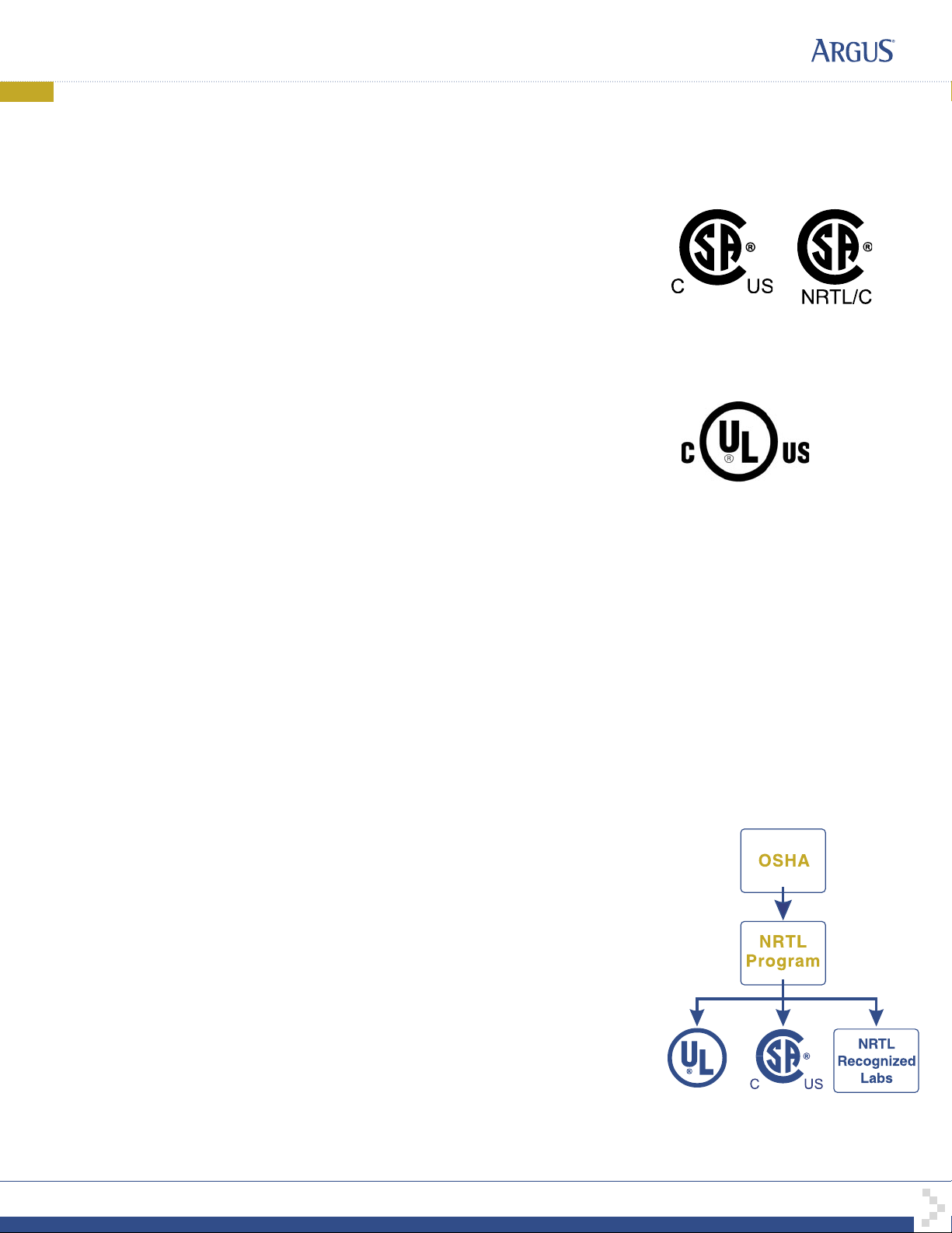
When these marks appear with the indicator “C and US” or “NRTL/C” it means that the product is
certied for both the US and Canadian markets, to the applicable US and Canadian standards. (1)
Argus rectier and power system products, bearing the aforementioned CSA marks, are
certied to CSA C22.2 No. 950 and UL 1950, or CSA/UL 60950.
As part of the reciprocal, US/Canada agreement regarding testing laboratories, the Standards Council
of Canada (Canada’s national accreditation body) granted Underwriters Laboratories (UL) authority to
certify products for sale in Canada. (2)
Only Underwriters Laboratories may grant a licence for the use of this mark, which indicates compliance
with both Canadian and US requirements. (3)
What are NRTLs and what do they do?
NRTLs are third party organizations recognized by OSHA, US Department of Labor, under the NRTL
program.
The testing and certications are based on product safety standards developed by US based standards
developing organizations and are often issued by the American National Standards Institute (ANSI). (4)
The NRTL determines that a product meets the requirements of an appropriate consensus-based
product safety standard either by successfully testing the product itself, or by verifying that a contract
laboratory has done so, and the NRTL certies that the product meets the requirements of the product
safety standard. (4)
The product on which either of these marks appear
has been certied by CSA as meeting applicable
Canada/US standards.
The product on which this mark
appears has been certied by UL
as meeting applicable Canada/US
standards.
When was the NRTL started and who governs it?
In 1983, in a suit brought on by an independent testing laboratory, OSHA was court ordered to remove
specic references to UL (Underwriters Laboratories) and FMRC (Factory Mutual Research Corporation)
from its regulations.
In 1988, OSHA revised its regulations to remove those references and the NRTL program was
established.
The NRTL Program is both national and international in scope with foreign labs permitted.
References:
Information in this document has been developed from the ofcial websites of the respective
organizations.
(1) www.csa-international.org
(2) www.scc.ca
(3) www.ulc.ca
(4) www.osha.gov
argusdcpower.com
048-554-10-I1 Rev C (2004/02)
Page 11

IMPORTANT SAFETY INSTRUCTIONS
SAVE THESE INSTRUCTIONS
1. Please read this manual prior to use to become familiar with the product’s numerous features and operating
procedures. To obtain a maximum degree of safety, follow the sequences as outlined.
2. This manual provides warnings and special notes for the user:
a. Points that are vital to the proper operation of the product or the safety of the operator are
indicated by the heading: WARNING.
b. A notation that is in Bold or Italic typeface covers points that are important to the
performance or ease of use of the product.
3. Before using the product, read all instructions and cautionary markings on the product and any equipment
connected to the product.
4. Do not expose the product to rain or snow; install only in a clean, dry environment.
5. CAUTION – Unless otherwise noted, use of an attachment not recommended or sold by the product
manufacturer may result in a risk of fire, electric shock, or injury to persons.
6. CAUTION – Do not operate the product if it has received a sharp blow, it has been dropped, or otherwise
damaged in any way – return it to a qualified service center for repair.
7. CAUTION – Do not disassemble the product – call our qualified service centers for servicing. Incorrect
reassembling may result in a risk of electrical shock or fire.
8. WARNING – The output voltages of the product are hazardous. Extreme caution should be maintained when
servicing or touching conductive components connected to the product’s output.
Page 12

This page intentionally left blank.
Page 13

TABLE OF CONTENTS
1 INTRODUCTION............................................................................................................................................................. 1
1.1 Scope of the Manual.....................................................................................................................................1
1.2 Product Overview..........................................................................................................................................1
1.3 Part Numbers and List Options.....................................................................................................................1
2 RECTIFIER FEATURES...................................................................................................................................................2
2.1 Front Panel....................................................................................................................................................2
2.2 Rear Panel....................................................................................................................................................3
2.3 True Module Fail Alarm................................................................................................................................. 3
2.4 Heat Dissipation............................................................................................................................................3
2.5 Over Temperature Protection .......................................................................................................................3
2.6 Wide AC Range ............................................................................................................................................ 4
2.7 AC Inrush/Transient Suppression.................................................................................................................4
2.8 Soft Start .......................................................................................................................................................4
2.9 Start Delay ....................................................................................................................................................4
2.10 Current Limit/Short Circuit Protection ...........................................................................................................4
2.11 Power Limiting............................................................................................................................................... 4
2.12 High Voltage Shutdown (HVSD)...................................................................................................................4
2.13 Battery Eliminator Operation.........................................................................................................................4
3 INSPECTION..................................................................................................................................................................5
3.1 Packing Materials..........................................................................................................................................5
3.2 Check for Damage........................................................................................................................................5
4 INSTALLATION..............................................................................................................................................................6
4.1 Safety Precautions........................................................................................................................................6
4.2 Shelf Preparation/Mounting ..........................................................................................................................6
4.3 Rectifier Module Insertion/Removal.............................................................................................................. 6
5 WIRING AND CONNECTIONS..........................................................................................................................................7
5.1 Safety Precautions........................................................................................................................................7
5.2 Tools Required..............................................................................................................................................7
5.3 Power System Chassis Ground and DC Ground Reference........................................................................ 7
5.4 AC Feeder Protection/Sizing......................................................................................................................... 7
5.5 AC Input Connections...................................................................................................................................7
5.6 Calculating Output Wire Size Requirements.................................................................................................8
5.7 DC Output Connections................................................................................................................................8
5.8 CAN Serial Ports........................................................................................................................................... 9
6 OPERATION................................................................................................................................................................10
6.1 Main Rectifier States................................................................................................................................... 10
6.2 Main Rectifier Modes .................................................................................................................................. 11
6.3 Can Bus Communications ..........................................................................................................................11
6.4 Factory Ranges and Defaults .....................................................................................................................12
7 SYSTEM STARTUP...................................................................................................................................................... 13
7.1 Check System Connections........................................................................................................................13
7.2 Verify AC and Power the Shelf ...................................................................................................................13
7.3 Check Battery Polarity and Connect........................................................................................................... 13
7.4 CXC Reset..................................................................................................................................................13
i
Page 14

8
MAINTENANCE ...........................................................................................................................................................14
8.1 Fan Replacement........................................................................................................................................14
8.2 MOV Replacement...................................................................................................................................... 15
9 ARGUS CONVENTIONS................................................................................................................................................16
9.1 Numbering System......................................................................................................................................16
9.2 Acronyms and Definitions ........................................................................................................................... 16
FIGURES
Figure 1–Cordex 125-4.4kW rectifier front panel ............................................................................................................. 2
Figure 2–CAN serial ports and termination selection....................................................................................................... 9
Figure 3–Fan replacement .............................................................................................................................................14
Figure 4–MOV replacement ...........................................................................................................................................15
ii
Page 15

1 Introduction
1.1 Scope of the Manual
This instruction manual explains the installation, interconnection, and operation of Argus Technologies’ Cordex
125-4.4kW modular switched mode rectifiers.
NOTE: To aid the user with installation, frequent reference is made to drawings located at the rear of the manual.
1.2 Product Overview
A complete Cordex rectifier system consists of one or more power modules in a common shelf enclosure. The
shelf has connections for AC inputs, DC output, and system communications.
Cordex rectifier modules use a high frequency, switched mode conversion technique to provide a fully regulated
and isolated DC output from the AC mains. The rectifier input is wide range to allow use on 208/220/240Va c
50/60Hz electrical service.
Rectifier power modules are “hot swappable” meaning they can be inserted or removed from the shelf with out
cutting power to or from the system or the load.
Additional power modules can be included with the system at the time of ordering or added after the shelf has
been installed.
The shelf rectifier system is designed to operate with the Argus Cordex System Controller (CXC).
The CXC allows the user to configure, monitor and control the entire DC power system from its touch screen
display similar to that used in a Personal Digital Assistant (PDA). Other features of the unit include temperature
compensation, auto equalization, remote access, dial out on alarm, battery diagnostics, as well as We b server
and Simple Network Management Protocol (SNMP) support for configuration and monitoring.
Details of controller operation are provided in the current version software manual.
There are two external CXC models of the system controller that communicate with the shelf via offset RJ-12
shelf connectors. The CXCR is mounted in a rack and the CXCP is (factory) mounted in a panel.
See manual #018-570-B2.
1.3 Part Numbers and List Options
This product is available to order under the following part numbers and list options:
Description Part Number/List Option
Cordex 125-4.4kW rectifier power module.................................................................................................010-589-20
Basic module......................................................................................................................................................*List 0
Charcoal finish with white (contrasting) silkscreen ..........................................................................................*List 56
Cordex 125-4.4kW 19” shelf, flush mounting, single phase ac input.........................................................030-769-20
Basic shelf, may be equipped with up to five Cordex 125-4.4kW modules**....................................................*List 0
19” mid-mount....................................................................................................................................................List 19
23” mid-mount....................................................................................................................................................List 23
DC output, bus bar adapters, 16” deep..............................................................................................................List 82
Kydex rear cover................................................................................................................................................List 89
Module blank......................................................................................................................................................List 90
* Default option
** See drawings at the rear of this manual.
The above information is valid at the time of publication. Consult factory for up-to-date ordering information.
Argus Technologies Ltd. 010-589-C0 Rev A WC
Printed in Canada. © 2007 Argus Technologies Ltd. ARGUS and CORDEX are trademarks of Argus Technologies Ltd. All Rights Reserved. Page 1 of 16
Page 16

2 Rectifier Features
2.1 Front Panel
LEDs
2.1.1 LEDs
The front panel LEDs provide:
Rectifier status summary will show the rectifier alarm status, communication fail status and rectifier on/off status.
2.1.1.1 AC ON
2.1.1.2 DC ON
2.1.1.3 ALARM
Thumbscrew
Figure 1–Cordex 125-4.4kW rectifier front panel
• Rectifier status summary,
• Rectifier software upgrade in progress indication,
• Locate module pattern.
The top LED (green) is on when AC is within valid range. The LED will flash (~2Hz) when AC is
outside the nominal range – AC voltage is invalid if the AC Mains Low or AC Mains High
alarm is active. The LED turns off when AC has failed.
The middle LED (green) is on when the rectifier is delivering power to the load. The LED will
flash when communication is lost. The LED turns off when the rectifier is off; e.g., when
commanded via the CXC.
The bottom LED (red) is on continuously in the event of an active Module Fail alarm; if the
module is unable to source power as a result of any of the following conditions:
Output fuse blown AC Mains Input Fail Module fail (ramp test fail)
High voltage (OVP) shutdown Thermal shutdown Local shutdown
UPF fail No output power Fan (1 and 2) fail.
The LED will flash (~2Hz) when a minor alarm is detected; if the modules output capability has
been reduced or a minor component failure is detected during the following conditions:
VAC meter fail AC foldback Remote equalize
Fan (1 or 2) fail Low output voltage High output voltage
Current limit (programmable option) Power limit (programmable option) High temperature foldback
Temperature sense fail Soft start operation Communications lost.
The LED remains off in the absence of an alarm. If the unit output is not connected to a battery
or parallel rectifier, the LED will extinguish if no AC power is present.
Argus Technologies Ltd. 010-589-C0 Rev A WC
Printed in Canada. © 2007 Argus Technologies Ltd. ARGUS and CORDEX are trademarks of Argus Technologies Ltd. All Rights Reserved. Page 2 of 16
Page 17

2.1.1.4 LED Activity During Software Upload
When a rectifier software upload is in progress, the LEDs will behave in a distinctly different way
to indicate new rectifier software is being transferred from the CXC.
When a rectifier data transfer is in progress, all three LEDs will flash in a sequence lasting 1.5
seconds. When the last LED is lit, the sequence is repeated beginning at the first LED.
2.1.1.5 LED Activity During ‘Locate Module’ Command from CXC
When the ‘locate module’ command has been received from the CXC, the LEDs will behave in
another distinct fashion so that the rectifier is easier to visually identify among adjacent
rectifiers.
This state is entered when commanded via the CXC. The LEDs will flash in a ping-pong pattern
repeating every 2 seconds.
The ping-pong pattern lights each LED sequentially. After the last LED is lit, each LED is lit in
reverse sequence. When the first LED is lit, the pattern repeats. The effect makes it appear as if
the light is bouncing between the first and last LED.
2.1.2 Mechanical
A thumbscrew is provided to secure the rectifier into the shelf. During normal operation the rectifier shall be
locked into position. A handle (or grip) is incorporated into the front panel to facilitate the removal of the rectifier
from the shelf. No special tools are required.
2.2 Rear Panel
Located on the rear panel of the rectifier is a single connector for shelf power and communications.
2.3 True Module Fail Alarm
The power modules have a “true” fail alarm. This provides a true indication of the power module’s ability to source
current. When the module’s output current drops below 2.5% of the rated output a low output current condition is
detected and the Module Fail detection circuit is activated. This circuit momentarily ramps up the output voltage to
determine if the module will source current. If no increase in current is detected, the Module Fail alarm is
activated. The module will test once every 60 seconds for the condition until current is detected. Output voltage
ramping will cease upon detection of current
1
. A minimum 2.5% load is required to avoid the Ramp Test Fail
alarm; this can typically be provided with the parallel system battery. Activation of this alarm could indicate a failed
module or a failed load.
NOTE: For Cordex rectifier systems without batteries (or with a very light load; below 2.5% of rated output) it is
recommended that the ramp test be disabled to avoid nuisance alarms. The Ramp Test feature is
enabled/disabled via the CXC menu item: Rectifiers, Configure Settings.
2.4 Heat Dissipation
Each rectifier module is equipped with at least one front-mounted fan. The fan operates at temperatures above
0°C (32°F). Cooling of the module is front-to-rear with the exhaust air exiting at the back. The fan is variable
speed; which is determined by heatsink temperature and load.
2.5 Over Temperature Protection
Each rectifier module is protected in the event of an excessive increase in temperature due to component failure
or cooling airflow blockage. During over temperature conditions, the rectifier limits the output power as well as the
output current. If temperature continues to increase, a shutdown of the rectifier is initiated. The rectifier shall
restart automatically if the temperature has returned to a safe level.
1
Under normal conditions, a battery connected to the output of the rectifier will draw current when the voltage ramp occurs. Therefore the rectifier fail
alarm will not be generated with a battery connected.
Argus Technologies Ltd. 010-589-C0 Rev A WC
Printed in Canada. © 2007 Argus Technologies Ltd. ARGUS and CORDEX are trademarks of Argus Technologies Ltd. All Rights Reserved. Page 3 of 16
Page 18

2.6 Wide AC Range
A minor alarm is generated when the AC input voltage drops below specification. Rectifier output power is
reduced linearly between 187Vac and 90Vac to 40% of the rated output power (the unit will deliver derated output
power down to 80Vac).
At 80Vac, the module will shut down and will not restart until the AC is greater than or equal to 90Vac; however,
the restart voltage depends on the load current. At reduced load current the unit may restart with the input voltage
as low as 100Vac.
For voltages above 265Vac, power factor and total harmonic distortion may be derated. Up to 312Vac, the
rectifier will be operational and shall not suffer any damage.
2.7 AC Inrush/Transient Suppression
The inrush current of the rectifier module is limited to the full load steady state line current to prevent surge on the
AC line. Modules are also protected from input lightning and transient surges in accordance with IEEE/ANSI
C62.41 Category B3.
2.8 Soft Start
To eliminate an instantaneous demand on the AC source, a soft start feature is employed. Soft Start, sometimes
referred to as “current walk-in”, works by gradually (up to five seconds) ramping the current limit up from zero to
the actual or defined customer setting. The rectifier output voltage is ramped up from the minimum voltage to the
float voltage.
2.9 Start Delay
The rectifier modules are equipped with a delay timer in order to stagger start a series of module s to pre v ent
excessive loading of generators upon start up. The built-in timer delays the turn on of the module depending on
the value selected (up to 120 seconds) via the CXC. A minimum one-second delay is preset to allow charging of
the input capacitors.
2.10 Current Limit/Short Circuit Protection
The current limit function determines the maximum output current limit of the rectifier module, regardless of output
voltage or power. Maximum output current is limited to a constant value down to short circuit condition. Current
limiting can be used to mate the rectifier output current ampacity to the needs of the load and parallel battery to
minimize excessive battery recharge current.
The rectifier will sustain a short circuit at the output terminals indefinitely. The maximum short circuit current shall
not exceed 105% of the rated full load current.
2.11 Power Limiting
Each rectifier module is designed to limit power output to the module specification. This enables more current to
be supplied at lower output voltages, and allows matching of output to the demand of constant power loads,
normally seen with telecom equipment.
This feature may also be used for a faster recharge of flooded batteries paralleled with the load.
NOTE: Current limiting overrides the power-limiting feature.
2.12 High Voltage Shutdown (HVSD)
This feature provides protection to the load from over voltage conditions originating from the rectifiers. It operates
by shutting down the offending rectifier module when a high output voltage condition occurs. Indication is through
the red Alarm (Module Fail) LED. Modules will restart automatically; however, if more than three over voltage
conditions occur in one minute, the module will latch off and remain shut down until it is reset via the CXC.
2.13 Battery Eliminator Operation
Rectifier modules maintain all specifications (except where indicated) with or without a battery attached in parallel
to the output; however, if a battery or another module supplying DC voltage in parallel is not present, there will be
no monitoring or control activity if there is an AC power failure or input fuse failure.
Argus Technologies Ltd. 010-589-C0 Rev A WC
Printed in Canada. © 2007 Argus Technologies Ltd. ARGUS and CORDEX are trademarks of Argus Technologies Ltd. All Rights Reserved. Page 4 of 16
Page 19

3 Inspection
3.1 Packing Materials
All Argus products are shipped in rugged, double walled boxes and suspended via solid inserts to minimize shock
that may occur during transportation. Packaging assemblies and methods are tested to International Safe Transit
Association standards.
Products are also packaged with Cortex. This plastic wrap contains a corrosive-inhibitor that protects the product
from corrosion for up to two years.
3.1.1 Returns for Service
Save the original shipping container. If the product needs to be returned for service, it should be packaged in its
original shipping container. If the original container is unavailable, make sure the product is packed with at least
three inches of shock-absorbing material to prevent shipping damage.
NOTE: Argus Technologies is not responsible for damage caused by the improper packaging of returned products.
3.2 Check for Damage
Prior to unpacking the product, note any damage to the shipping container. Unpack the product and inspect the
exterior for damage. If any damage is observed contact the carrier immediately.
Continue the inspection for any internal damage. In the unlikely event of internal damage, please inform the
carrier and contact Argus Technologies for advice on the impact of any damage.
Verify that you have all the necessary parts per your order for proper assembly.
Argus Technologies Ltd. 010-589-C0 Rev A WC
Printed in Canada. © 2007 Argus Technologies Ltd. ARGUS and CORDEX are trademarks of Argus Technologies Ltd. All Rights Reserved. Page 5 of 16
Page 20

4 Installation
This chapter is provided for qualified personnel to install the product, which shall be mounted in a clean and dry
environment.
NOTE: To aid the user with installation, frequent reference is made to drawings located at the rear of the manual.
4.1 Safety Precautions
WARNING
Hazardous voltages are present at the input of power systems. The DC output from the rectifiers
is classified as hazardous voltage and has a high short circuit current capacity that may cause
severe burns and electrical arcing.
Before working with any live battery or power system/distribution center, the following precautions should be
followed:
• Remove all metallic jewelry; e.g., watches, rings, eyeglasses, necklaces.
• Wear safety glasses with side shields at all times during installation.
Metallic tools must be insulated.
The installer should follow all applicable local rules and regulations for electrical and battery installations; e.g.,
CSA, UL, CEC, NEC, OSHA, and local fire codes.
4.2 Shelf Preparation/Mounting
The 19” shelf has been designed for flush mounting in a standard 19” relay rack. Universal mounting brackets
allow for mid-mounting in a 19” or 23” rack. The configuration depends on the options chosen. See dra wing 030769-06.
NOTE: The shelf shall be mounted in a clean and dry environment. Allow at least 1.75” of free space in front of the unit
for unrestricted cooling airflow.
Mounting brackets accommodate either 1” or 1-3/4” rack spacing. The shelf should be mounted to the rack using
at least two #12 – 24 x 1/2” screws in each bracket. Philips-type screws and screwdriver should be used to
eliminate the possibility of slippage and scratching of the unit’s exterior. Washers (such as internal tooth) or
special screws that are designed to cut through the painted surface should be used to ensure a good cha ssis
ground.
4.3 Rectifier Module Insertion/Removal
Insert by placing the rectifier module on the shelf bottom and sliding the module into the rear connector (inside of
the shelf). Apply pressure on the module handle to engage the rear connector in the shelf receptacle.
NOTE: It is recommended that the first module be inserted into the front leftmost position using the side of the shelf as a
guide. Subsequent modules may be inserted using the previous module as a guide.
Tighten the screw on the bottom of the faceplate to secure the module to the shelf.
NOTE: Do not force a module into position if it does not seat properly. All modules are keyed to ensure that the correct
module (voltage/polarity) type is used.
To remove a module, loosen the screw on the bottom of the faceplate. Grasp handle and pull out, sliding the
module away from the rear connector and out of the shelf.
Argus Technologies Ltd. 010-589-C0 Rev A WC
Printed in Canada. © 2007 Argus Technologies Ltd. ARGUS and CORDEX are trademarks of Argus Technologies Ltd. All Rights Reserved. Page 6 of 16
Page 21

5 Wiring and Connections
This chapter provides cabling details and notes on cable sizing for DC applications with respect to the Argus
Cordex 125-4.4kW modular switched mode rectifier.
5.1 Safety Precautions
WARNING
Hazardous AC voltages may be present. Ensure power at the AC service panel is off before
attempting work on the AC connections. Use a voltmeter to verify the absence of voltage. Clearly
mark the correct polarity of the battery leads before commencing work on DC connections.
Refer to the previous (Installation) chapter for additional safety precautions.
5.2 Tools Required
Various tools are essential for product installation. Use this list as a guide:
• Slot head screwdrivers (blade sizes: 1/4”, 1/8”, 1/16”)
• Philips head screwdriver, #2 (tip size 3/16”)
• Digital voltmeter equipped with test leads
• Adjustable 125/220Vdc load (optional)
• Cutters and wire strippers
• Crimping tool (optional for large gauge wire)
• Socket and rachet set (Imperial measure).
5.3 Power System Chassis Ground and DC Ground Reference
WARNING
For safety reasons, ensure the system is properly bonded to the building’s ground grid.
125/220Vdc systems are typically floating; i.e., not connected to earth ground.
Connect the chassis ground to the site ground to ensure correct operation of the system and to prevent drifting
floating analog (especially current) readings.
5.4 AC Feeder Protection/Sizing
To maximize system reliability, each power module should be fed from a dedicated protection feeder breaker
located at the AC distribution panel. The feeder breaker can also act as the disconnect device for the connected
module. Refer to the specifications at the front of this manual for Argus recommendations.
5.5 AC Input Connections
CAUTION: AC input wires should be routed in flexible or rigid conduit as far away as possible
from the DC power wires to minimize EMI disturbances.
Ensure all modules are removed from the shelf.
The wireway is designed for two customer-supplied 1” conduit fittings for AC supply located o ne on each side of
the shelf.
Remove the metal covers (2 places) from the rear of the shelf to expose the AC input terminal blocks, L1 and L2
for each rectifier. Each terminal pair relates to an individual power module as marked.
Attach the conduit retainers to the wireway hole(s) and route the AC cables through.
Secure the wires to the AC input and chassis ground terminals as required.
Tighten the cable connector to the AC cable (conduit similar).
Replace rear cover(s) once all connections have been completed.
Argus Technologies Ltd. 010-589-C0 Rev A WC
Printed in Canada. © 2007 Argus Technologies Ltd. ARGUS and CORDEX are trademarks of Argus Technologies Ltd. All Rights Reserved. Page 7 of 16
Page 22

5.6 Calculating Output Wire Size Requirements
Wire size is calculated by first determining the appropriate maximum voltage drop requirement. Using the formula
below calculate the CMA wire size requirement. Determine the size and number of conductors required to satisfy
the CMA requirement.
CMA = (A x LF x K) / AVD, where:
CMA = Cross section of wire in circular MIL area
A = Ultimate drain in amps
LF = Conductor loop feet
K = 11.1 constant factor for commercial (TW type) copper wire
AVD = Allowable voltage drop
Check again that the ampacity rating of the cable meets the requirement for the installation application. Consult
local electrical codes (NEC, CEC, etc.) for guidelines. If required, increase the size of the cable to meet the cod e.
5.7 DC Output Connections
WARNING
Leave cables or bus bars disconnected at battery and verify output polarity using a voltmeter.
Make battery connections only after all other wiring is completed.
DC output wire shall be UL approved XHHW or RHH/RHW (for Canadian users, RW90 Type). Control and sense
wires shall be UL approved Style 1015 (for Canadian users, TEW type).
5.7.1 Cable
Terminate cable leads with appropriate crimp lugs for 3/8” holes on 1” centers.
Secure the positive and negative to the shelf output post of the correct polarity; i.e., +Vcable to +Vpost. Ensure
the washers are on the bolts in the same order in which they were shipped from the factory. Tighten the bolts as
per Customer Connections drawing at the rear of this manual.
5.7.2 Bus Bar
Bus bar adapters may be factory-installed, for the option selected, to easily accommodate direct connections to
customers’ vertical bus bars.
Secure the positive and negative to the shelf output post of the correct polarity; i.e., +Vcable to +Vpost. Ensure
the washers are on the bolts in the same order in which they were shipped from the factory. Tighten the bolts as
per Customer Connections drawing at the rear of this manual.
Argus Technologies Ltd. 010-589-C0 Rev A WC
Printed in Canada. © 2007 Argus Technologies Ltd. ARGUS and CORDEX are trademarks of Argus Technologies Ltd. All Rights Reserved. Page 8 of 16
Page 23

5.8 CAN Serial Ports
Two CAN Serial ports (modular jacks with offset latches), are provided for communications with Argus’ Cordex
rectifiers and other CAN-enabled equipment. These are located on the left side of the shelf (as viewed from the
front).
Daisy-chain from shelf to shelf (CAN OUT of one shelf to CAN IN of another) as necessary and ensure that only
the last shelf is terminated. See Figure 2.
5.8.1 CAN Termination
A jumper (or switch depending on your configuration) allows setting of the CAN OUT to be open (to the next shelf
in the system) or terminated. Termination must be enabled in final shelf on the CAN bus only. Access term ination
selection (inside the shelf) by removing the leftmost rectifier #1 (MDL 1).
Figure 2–CAN serial ports and termination selection
Argus Technologies Ltd. 010-589-C0 Rev A WC
Printed in Canada. © 2007 Argus Technologies Ltd. ARGUS and CORDEX are trademarks of Argus Technologies Ltd. All Rights Reserved. Page 9 of 16
Page 24

6 Operation
6.1 Main Rectifier States
Rectifier operation can be broken up into five main states:
1. Off,
2. Start delay,
3. Soft start,
4. Normal operation,
5. Turning off.
Each state is characterized as being distinct and necessary for the operation of the rectifier. These states are
briefly described below.
6.1.1 Off State
The rectifier will be in the Off state immediately after power is applied to the rectifier or after a rectifier shutdown.
The shutdown source may be remote or local shutdown, AC shutdown, OVP or thermal shutdown.
When the rectifier is in this state the DC-DC converter is turned off and the CXC will be monitoring its inputs for
the proper conditions to begin the start up sequence.
When the conditions have been met for the rectifier to start up, it will transition to the Start Delay state.
6.1.2 Start Delay State
When the rectifier is in the Start Delay state, the DC-DC converter is held off and still not sourcing power and is
waiting for a given amount of time before transitioning to the next state.
When in this state, the CXC continues to monitor its inputs.
After the Start Delay state the rectifier will transition to the Soft Start state.
NOTE: Soft start, or current walk-in, gradually increases the voltage and current output of the rectifier upon startup. This
is done to reduce the instantaneous load on the AC source.
6.1.3 Soft Start State
When the Soft Start state is entered, the rectifier will be turned on and the output voltage and output current will
be gradually increased. If a load is present, the rectifier will begin to source power.
When the voltage and current limit ramps have finished, the rectifier will transition to the Normal Operation state.
6.1.4 Normal Operation State
The Normal Operation state is the state that the rectifier will be in performing all of the rectifier functions and
features specified herein.
From this state, the only valid transition is to the Turning Off state. This transition will happen if the rectifier is
required to shutdown.
6.1.5 Turning Off State
The Turning Off state is entered because a short delay is required before the rectifier actually turns off to take
care of any initialization requirements.
When this short delay has elapsed, a transition to the Off state is made.
Argus Technologies Ltd. 010-589-C0 Rev A WC
Printed in Canada. © 2007 Argus Technologies Ltd. ARGUS and CORDEX are trademarks of Argus Technologies Ltd. All Rights Reserved. Page 10 of 16
Page 25

6.2 Main Rectifier Modes
In addition to Main Rectifier States, there is a set of Main Rectifier Modes. These modes can be divided into two
categories as follows:
6.2.1 Output Voltage Modes
Voltage modes can be thought of as modes that, under software control, can directly adjust the output voltage.
The qualification of ‘under software control’ is made because there are proce sses that oc cur in the rectifier that
can change the output voltage that do not adjust the output voltage directly (such as the rectifier being in current
limit).
The following table lists the five Output Voltage Modes and a description of when they are active:
Output Voltage Modes Active when…
Float Output voltage is set to the float voltage setting.
Equalize Output voltage is set to the equalize voltage setting.
Battery Test Output voltage is set to the battery test voltage setting.
Safe Output voltage is set to the safe mode voltage setting.
Manual Test Output voltage can be manually adjusted outside of the standard adjustment ranges.
6.2.2 Output Current/Power Modes
Table A–Output voltage modes
These modes directly affect the output current and power.
The following table lists the four Output Current/Power Modes and a description of when they are active:
Output Current/Power Mode Active when…
Temperature foldback mode Output current and power limit have been reduced due to high temperature of the
AC foldback mode Output current and power limit have been reduced due to low AC input voltage. Note:
Short circuit foldback mode Output current limit has been reduced due to a short circuit at the output.
Internal fault foldback mode Output current limit has been reduced due to an internal fault.
6.3 Can Bus Communications
The CAN bus is used for communication between the rectifier and CXC.
The communication between the rectifier and CXC consists of command s and data transfer that are used during
the operation of the power system to configure the rectifier with system settings and to monitor rectifier status.
heatsink or internal ambient temperature sensor.
this will reduce the risk of tripping an AC breaker due to increased AC current draw as
the AC voltage decreases.
Table B–Output current/power modes
Argus Technologies Ltd. 010-589-C0 Rev A WC
Printed in Canada. © 2007 Argus Technologies Ltd. ARGUS and CORDEX are trademarks of Argus Technologies Ltd. All Rights Reserved. Page 11 of 16
Page 26

6.4 Factory Ranges and Defaults
The following tables lists the rectifier settings/ranges/defaults; changes are made via the CXC:
Setting Range (minimum to maximum) Default
Float (FL) Voltage 90 – 160V 130.5V
Equalize (EQ) Voltage 90 – 160V 132.9V
Battery Test (BT) Voltage 90 – 160V 106.3V
OVP See note below – 160V 137.8V
Current Limit (CL) 9 – 100% 100%
Power Limit (PL) 0 – 100% 100%
Module Start Delay 0 – 250s 1s
System Start Delay 0 – 600s 0s
Low Voltage Alarm (LVA) 90 – 160V 106.3V
High Voltage Alarm (HVA) 90 – 160V 134.1V
EQ Timeout 1 – 2399h 30h
BT Timeout 1 – 250h 8h
Softstart Ramp-rate Normal/Fast Normal
CL/PL Alarm Enable/Disable Enable
Remote Shutdown Enable/Disable Enable
Ramp Test Enable/Disable Enable
Table C–Cordex 125-4.4kW factory ranges and defaults
NOTE: OVP cannot be set below the present system/FL/EQ/BT voltage setting or the safe mode voltage of 118.9V.
Argus Technologies Ltd. 010-589-C0 Rev A WC
Printed in Canada. © 2007 Argus Technologies Ltd. ARGUS and CORDEX are trademarks of Argus Technologies Ltd. All Rights Reserved. Page 12 of 16
Page 27

7 System Startup
After completing the shelf wiring and installation, perform the following startup and test procedure to ensure
proper operation:
7.1 Check System Connections
• Ensure AC is off, battery is disconnected, and all power modules are removed from the shelf.
• Triple check the polarity of all connections.
7.2 Verify AC and Power the Shelf
• Install one power module.
• Verify AC input voltage is correct and turn on the corresponding AC input feeder breaker.
• The power module OK LED should illuminate after a preset start delay.
• Using the CXC, test functionality of various module alarms and controls.
7.3 Check Battery Polarity and Connect
• Verify correct battery polarity using a voltmeter (ensuring no cells or batteries are reversed).
• Connect battery as required to the output of the system or turn on battery breaker.
• Install remaining power modules.
• In the adjustments menu of the CXC, set Float and Equalize voltage to the levels specified by the battery
manufacturer.
• Using the CXC, test functionality of various module alarms and controls. In addition, perform a load test with
the system using a resistive load box as needed.
7.4 CXC Reset
The reset button located on the front panel of the optional CXC is for restarting the microprocessor. When
pressed momentarily, the unit beeps twice then resets. The front-panel LED’s will illuminate temporarily, but will
extinguish after the system has finished its 15-second self-test.
Argus Technologies Ltd. 010-589-C0 Rev A WC
Printed in Canada. © 2007 Argus Technologies Ltd. ARGUS and CORDEX are trademarks of Argus Technologies Ltd. All Rights Reserved. Page 13 of 16
Page 28

8 Maintenance
Although very little maintenance is required with Argus systems, routine checks and adjustments are
recommended to ensure optimum system performance. Qualified service personnel should do repairs.
The following table lists a few maintenance procedures for this system. These procedures should be performed at
least once a year.
WARNING: HIGH VOLTAGE AND SHOCK HAZA RD.
Use extreme care when working inside the shelf while the system is energized.
Do not make contact with live components or parts.
Circuit cards, including RAM chips, can be damaged by static electricity. Always wear a grounded
wrist strap when handling or installing circuit cards.
Procedure Date Completed
Clean ventilation openings
Inspect all system connections (re-torque as necessary)
Verify alarm/control settings
Verify alarm relay operation
Rectifiers could fail due to lack of maintenance and should be checked frequently until a proper mainte nance
schedule is developed to suit site conditions.
Table D–Sample maintenance log
8.1 Fan Replacement
Figure 3–Fan replacement
Argus Technologies Ltd. 010-589-C0 Rev A WC
Printed in Canada. © 2007 Argus Technologies Ltd. ARGUS and CORDEX are trademarks of Argus Technologies Ltd. All Rights Reserved. Page 14 of 16
Page 29

1. Shut off the unit and unscrew the front fastener that secures the power module to the shelf.
2. Slide the module 10 cm (4”) out of the shelf and wait two minutes for module capacitors to discharge.
3. Remove the four screws (two each side) that secure the front panel to the module chassis.
4. Slide the front panel out.
5. Disconnect the fan power lead wires (one set per fan) and front panel ribbon cable from the module.
6. Remove the screws that secure the fans to the front panel.
7. Note the direction of airflow and remove the fans from the front panel.
8. Install the replacement fans following the preceding steps in reverse order.
8.2 MOV Replacement
Figure 4–MOV replacement
The MOVs (metal oxide varistor) are used to protect the power modules from power line surges and the surges
caused by lightning strikes. High capacity surges may permanently damage MOVs but they are easily replace d in
the field using the following procedure:
1. Shut off the unit and unscrew the front fastener that secures the power module to the shelf.
2. Slide the module 10 cm (4”) out of the shelf and wait two minutes for module capacitors to discharge.
3. Turn the module around to face the back of the unit and remove the one screw (module bottom toward the
rear) securing the MOV cover.
4. Remove the cover and locate the MOV printed circuit board (PCB).
5. Remove the three screws that secure the MOV PCB.
6. Decontaminate the area and unit with flux remover or a similar cleaning compound. This is to remove any
metallic particles or carbon, which may have been deposited when the MOV failed.
7. Install the replacement MOV PCB following the preceding steps in reverse order.
Argus Technologies Ltd. 010-589-C0 Rev A WC
Printed in Canada. © 2007 Argus Technologies Ltd. ARGUS and CORDEX are trademarks of Argus Technologies Ltd. All Rights Reserved. Page 15 of 16
Page 30

9 Argus Conventions
9.1 Numbering System
Argus Technologies uses an eight-digit drawing number system, which is broken into three blocks. The first three
digits describe the category of the product; e.g., rectifier or fuse panel. The next three digits indicate the sequence
in which the product number was allocated in a particular category. The last two digits indicate the type of
drawing, for example:
“-06” Outline Drawing
“-08” Customer Connections
“-20” Main Assembly
Argus uses an eight-digit part numbering system for all components and sub assemblies. Each part is covered by
its own unique number. Due to the quantity, categories will not be listed within this manual.
9.2 Acronyms and Definitions
AC Alternating current
ANSI American National Standards Institute
AWG American Wire Gauge
BTU British thermal unit
CAN Controller area network
CEC Canadian Electrical Co de
CSA Canadian Standards Association
CX Cordex™ series; e.g., CXC for C
DC Direct current
DHCP Dynamic Host Configuration Protocol
EIA Electronic Industries Alliance
EMC Electromagnetic compatibility
EMI Electromagnetic interference
ERM E
ESD Electrostatic Discharge
FCC Federal Communications Commission (for the USA)
HVSD H
IEC International Electrotechnical Commission
IEEE Institute of Electrical and Electronics Engineers
IP Internet Protocol
LED Light emitting diode
LVD Low voltage disconnect
MOV Metal oxide varistor
MTBF Mean time between failures
NC Normally closed
NEC National Electrical Code (for the USA)
NO Normally open
OSHA Occupational Safety & Health Administration
OVP Over voltage protection
RAM Random access memory
RU Rack unit (1.75”)
TCP/IP Transmission Control Protocol / Internet Protocol
THD Total harmonic distortion
UL Underwriters Laboratories
lectromagnetic Compatibility and Radio Spectrum Matters
igh voltage shutdown
ordex System Controller
Argus Technologies Ltd. 010-589-C0 Rev A WC
Printed in Canada. © 2007 Argus Technologies Ltd. ARGUS and CORDEX are trademarks of Argus Technologies Ltd. All Rights Reserved. Page 16 of 16
Page 31

LTR
B ADDED MOUNTING BRACKETS S.D.W.
REVISIONS
DESCRIPTION APPDDATE
REV BY
16.10 408.9
15.28 388.2
0
0.93 23.6
4.4kW CORDEX MODULE
010-589-20
0
17.40 441.9
17.40 441.9
11.86 301.2
11.36 288.5
10.36 263.1
9.86 250.4
6.92 175.7
7.42 188.4
5.92 150.3
5.42 137.6
0
6.97 177.0
6.55 166.4
6.05 153.7
5.05 128.3
0
REAR COVER AND MODULES ARE HIDDEN
REAR VIEW
(LIST 82 OUTPUT BARS)
TOP VIEW
REAR COVER IS HIDDEN
(LIST 82 OUTPUT BARS)
17.17 436.0
LIST 90
MODULE BLANK
FRONT VIEW
KYDEX REAR COVER
LIST 89
REAR ISOMETRIC VIEW
DIMENSIONS ARE IN INCHES WITH METRIC [mm] IN BRACKETS: INCHES [mm]
c 2006 ARGUS TECHNOLOGIES
O
THESE DESIGNS AND SPECIFICATIONS ARE THE PROPERTY OF
ARGUS TECHNOLOGIES AND SHALL NOT BE COPIED OR USED
FOR MANUFACTURING WITHOUT ITS WRITTEN CONSENT.
2006/05
DESIGN
WH/EOF
EOF/J.U.
DRAWN
G.S.
CHECKED
G.S.
APPROVED
TOLERANCES
X.X 0.04"
X.XX 0.02"
X.XXX 0.01"
TITLE
OUTLINE, 19" SHELF
ISSUE
DATE
SIZE DWG NO.TYPE
B
D2
MATERIAL
2006/05
2006/05
FINISH
2006/05
[X] 1mm
[X.X] 0.5mm
[X.XX] 0.25mm
SCALE
4.4kW CORDEX
SHEET
030-769-06
N.T.S.
1 2
OF
REV
B
Page 32

17.08 433.9
5.03 127.7
0
4.4kW CORDEX MODULE
010-589-20
TOP VIEW LIST 19 - 19" MID-MOUNT
LIST 90
MODULE BLANK
17.40 441.9
18.31 465.1
19.0 483
19.4 493
FRONT VIEW LIST 19 - 19" MID-MOUNT
5.03 127.7
6.97 177.0
5.49 139.3
3.74 94.9
3.24 82.2
1.49 37.7
0.65 16.6
0
0
TOP VIEW LIST 23 - 23" MID-MOUNT
6.97 177.0
6.74 171.1
5.49 139.3
1.49 37.7
0.24 6.0
0
17.40 441.9
22.31 566.7
23.06 585.7
FRONT VIEW LIST 23 - 23" MID-MOUNT
c 2006 ARGUS TECHNOLOGIES
DIMENSIONS ARE IN INCHES WITH METRIC (mm) IN BRACKETS: INCHES [mm]
THESE DESIGNS AND SPECIFICATIONS ARE THE PROPERTY OF
ARGUS TECHNOLOGIES AND SHALL NOT BE COPIED OR USED
FOR MANUFACTURING WITHOUT ITS WRITTEN CONSENT.
TITLE
OUTLINE, 19" SHELF
ISSUE
DATE
DWG NO.
SIZE
TYPE
D2
B
SCALE
4.4kW CORDEX
SHEET
030-769-06
N.T.S.
OF
2 2
REV
B
Page 33

LTR DESCRIPTION
B ADDED MOUNTING BRACKETS S.D.W.
SWITCH SETTING FOR CAN TERMINATION
REVISIONS
REV BY
APPDDATE
AC WIREWAY
BLANK PLATE
REAR VIEWS
SEE AC INPUT
DETAILS
AC INPUT DETAILS
SINGLE PHASE INPUTS, 208V - 277VAC
L1
L2
L1
L2
L1
L2
L1
L2
L1
L2
REMOVE COVERS
AC WIREWAY (2 PLACES)
1.3 [34] HOLE FOR
CUSTOMER SUPPLIED
1" CONDUIT FITTING
PROTECTIVE EARTH
TERMINAL
2 PLACES
J8
J7
CAN OUT RJ12 OFFSET
PIN OUT (J8)
GND1.
CAN H2.
NOT CONNECTED3.
CAN L4.
NOT CONNECTED5.
NOT CONNECTED6.
CAN
TERMINATED
CAN IN RJ12 OFFSET
PIN OUT (J7)
GND1.
CAN H2.
NOT CONNECTED3.
CAN L4.
NOT CONNECTED5.
NOT CONNECTED6.
CAN
UNTERMINATED
c 2006 ARGUS TECHNOLOGIES
O
THESE DESIGNS AND SPECIFICATIONS ARE THE PROPERTY OF
ARGUS TECHNOLOGIES AND SHALL NOT BE COPIED OR USED
FOR MANUFACTURING WITHOUT ITS WRITTEN CONSENT.
WH
DESIGN
J.U.
DRAWN
CHECKED
G.S. 2006/05
APPROVED
TOLERANCES
X.X 0.04"
X.XX 0.02"
X.XXX 0.01"
TITLE
CUSTOMER CONNECTION
19" SHELF, 4.4kW CORDEX
ISSUE
DATE
DWG NO.
SIZE
TYPE
D2
B
2006/05
2006/05
[X] 1mm
[X.X] 0.5mm
[X.XX] 0.25mm
SHEET
030-769-08
MATERIAL
FINISH
PER P.O. and
Doc. 070-024-83
SCALE
N.T.S.
OF
1 2
REV
B
Page 34

POSITIVE (+)
OUTPUT TERMINAL
(CUSTOMER SUPPLIED)
DC WIRING
LIST 89 - REAR COVER
3/8" FLAT WASHER
3/8" LOCK WASHER
3/8-20 NUT
NEGATIVE (-)
OUTPUT TERMINAL
3/8" 2 HOLE COMPRESSION TERMINAL
1" SPACING (CUSTOMER SUPPLIED)
3/8" FLAT WASHER
3/8-20 x 1" HEX BOLT
POSITIVE (+) BUS BAR
(CUSTOMER SUPPLIED)
3/8" FLAT WASHER
3/8-20 x 1" HEX BOLT
POSITIVE (+)
OUTPUT TERMINAL
3/8" FLAT WASHER
3/8" LOCK WASHER
3/8-20 NUT
NEGATIVE (-)
OUTPUT TERMINAL
NEGATIVE (-) BUS BAR
(CUSTOMER SUPPLIED)
REAR VIEW - DC CABLE INSTALLATION
REAR VIEW - DC CABLE INSTALLATION
REAR COVER NOT SHOWN
REAR VIEW - BUS BAR INSTALLATION
c 2006 ARGUS TECHNOLOGIES
O
THESE DESIGNS AND SPECIFICATIONS ARE THE PROPERTY OF
ARGUS TECHNOLOGIES AND SHALL NOT BE COPIED OR USED
FOR MANUFACTURING WITHOUT ITS WRITTEN CONSENT.
TITLE
CUSTOMER CONNECTION
19" SHELF, 4.4kW CORDEX
ISSUE
DATE
DWG NO.
SIZE
TYPE
D2
B
SCALE
SHEET
030-769-08
N.T.S.
OF
2 2
REV
B
Page 35

ARGUS TECHNOLOGIES DRAWING #010-589-G0 SPARE PARTS LIST POWER MODULE, CORDEX 125-4.4KW
Type WD
APPROVED: ______________
ISSUED: ______________
ITEM QTY PART NO. REV DESCRIPTION CIRCUIT DESIGNATION
OR REMARKS
List 0; ON SITE:
1 2 747-212-20 Assy,Fan,Cordex 24-3.1kW Fn100,101
List 0
2 1 707-374-20 Assy,PCB,Trans Protn,Cordex 3.6kW (A8)
List 0
Page 36

FACTORY SERVICE INFORMATION
Technical Support
Technical support staff are available for answering general questions related to installation, operation
and maintenance of Argus products. In Canada and the USA, call Argus toll free 7:30 am to 5:00 pm
Pacific Standard Time at:
+1-888 GO ARGUS
(+1-888-462-7487)
For emergencies, call +1-888-GO-ARGUS 24 hours a day, seven days a week.
Customers outside Canada and the USA, call +1-604-436-5547 for technical support.
Training
Argus offers various levels of product and technical training. These workshops provide a mix of
theory and hands on application for qualified customers. Please consult your sales representative for
course schedules, locations and costs, or visit our website at www.argusdcpower.com.
Factory Repair and Servicing
All service, beyond initial adjustments, should be carried out by qualified factory service personnel.
For these procedures, please contact Argus Technologies at the locations listed to the right.
Product Returns
Before returning any product for service, please obtain a Return Material Authorization (RMA) number
from an Argus factory service representative. The representative will require the model and serial
number, as well as a brief description of the problem prior to issuing the RMA number. All material
must be pre-authorized before being returned.
See document 048-507-10 “Warranty and Repair Information” for more details.
Moving and Storage
Units must be suitably packed in the original shipping container (or equivalent) prior to re-shipping.
The box should be completely enclosed and constructed of wood or double-wall, corrugated
cardboard. At least 3” of foam or shock absorbing packing material must surround the unit.
Factory Service Centers
Canada and International
Argus Technologies Ltd.
ATTN: RMA Returns
7033 Antrim Avenue
Burnaby, BC, V5J 4M5 Canada
Tel: +1 604 436 5900
+1 604 436 1233
Fax:
Email: returns@argusdcpower.com
USA
Argus Technologies Inc.
ATTN: RMA Returns
3116 Mercer Avenue
Bellingham, WA, 98225 USA
Tel: +1-360 756 4904
+1-360 647 0498
Fax:
Email: returns-usa@argusdcpower.com
Asia-Pacific
PCM Electronics (Dong Guan) Co., Ltd.
Hongli Industrial Area, Miaobian, Liaobu Town,
Dongguan City, Guangdong Province,
523400 China
Tel: +86 755 8895 3310
+86 755 8895 3307
Fax:
Authorized Service Center
Argentina
Argus Technologies de Argentina
Belen 315, Capital Federal, Buenos Aires,
1407l Argentina
Tel: +54 (11) 4672 4821
+54 (11) 4504 4698
Fax:
Cell: +54 9 (11) 4993 9996
Email: lkleiman@argus.ca
Asia
Argus Technologies Asia Pte Ltd
Blk 6 Tagore Lane #160
Singapore 787570
Tel: +65 6458 8900
+65 6458 2122
Fax:
Australia
CPS National
8/376 Newbridge Rd
Moorebank, NSW, 2170 Australia
Tel: +61 02 9822 8977
+61 02 9822 8077
Fax:
Australia/New Zealand
Alpha Power Systems Pty Ltd
Unit 3, 30 Heathcote Road
Moorebank, NSW, 2170 Australia
Tel: +61 02 9602 8331
+61 02 9602 9180
Fax:
Century Yuasa
37 - 65 Colbalt Street
Carole Park QLD 4300
Australian Sales & Service
Tel: +61 07 3361 6587
+61 07 3361 6705
Fax:
New Zealand Sales & Service
Tel: +64 9 978 6689
+64 9 978 6677
Fax:
Canada
Compower Systems Inc.
118 Tiffield Road
Toronto, ON, M1V 5N2 Canada
Tel: +1 416 293 3088
+1 416 293 0671
Fax:
Europe
Alpha Technologies Europe Ltd.
Cartel Business Estate
Edinburgh Way
Harlow, Essex, CM20 2DU UK
Tel: +44 1279 422110
+44 1279 423355
Fax:
Mexico & Central America
Technologies Argus First De Mexico SA de CV
Anatole France No. 17
Col. Polanco
Mexico City, 11560 Mexico
Tel: +52 55 5280 6990
+52 55 5280 6585
Fax:
South America
Argus Technologies Argentina
Santo Tome 2573, Capital Federal
Buenos Aires, 1416 Argentina
Tel: +54 11 4504 4698
+54 9 11 4993 9996
Cell:
E-pager: 541149939996@nextel.net.ar
Turkey
IPC Enerji Elk San ve TIC AS
Inonu cad. Kanarya sok. No:20
Yenisahra - Kadikoy
Istanbul, Turkey
Tel: +90 216 317 41 42
+90 216 472 90 66
Fax:
Canada and USA toll free 24 hour emergency technical support:
048-527-10-I1 Rev L (09/2007)
+
1 888 GO ARGUS (462 7487) Outside North America: +1 604 436 5547
 Loading...