

Page 1

Installation Guidelines
To fit the
Alpha CombiMax 350 and 600
in a remote location from the boiler
For Technical help or for Service call ...
ALPHA HELPLINE
Tel: 0870 3001 964
Nepicar House, London Road,
Wrotham Heath, Sevenoaks,
Kent TN15 7RS
These guidelines must be used in conjunction with the Installation instructions provided
with the selected combination boiler and CombiMax.
Only a CombiMax produced after February 1999 can be installed remote from the boiler.
Page 2
1 INTRODUCTION
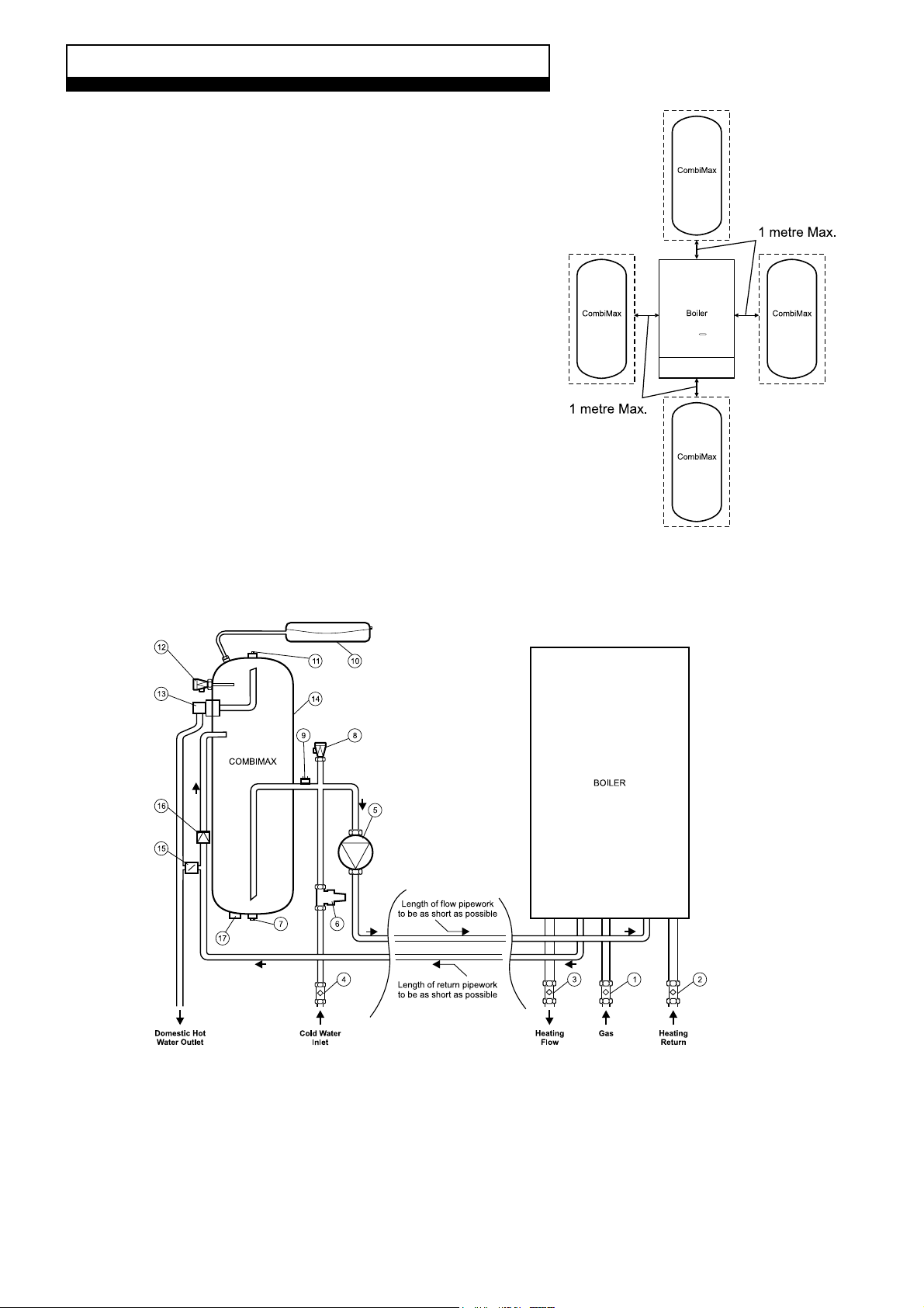
The Alpha CombiMax has been designed to fit onto the left hand side
of an Alpha 240/280 boiler. However, it is now possible (using a
CombiMax 350 or 600 produced after February 1999, i.e. from Serial
No. A906) to install it up to a distance of 1 metre from the boiler in the
positions shown in Fig. 1.
The pipework between the boiler and CombiMax must be kept as
short as possible and be no more than 1 metres in length, with the
number of bends kept to a minimum.
Notes: 1. A CombiMax produced before February 1999, i.e. before
Serial No. A906 must not be fitted remote from the boiler.
2. A CombiMax fitted remote has no casing.
Possible locations
for the CombiMax
in relation to the
boiler.
1.1 CombiMax Schematic - remote location from boiler
Fig. 1
1. Gas service cock
2. On/Off valve and filter
3. On/Off valve
4. On/Off valve and filter
5. DHW pump
6. Pressure reducing valve with filter and check valve
7. Drain point
8. DHW expansion relief valve
9. Store thermostat
Alpha CombiMax Remote Location
2
10. DHW expansion vessel
11. Manual air vent
12. DHW temperature/pressure relief valve
13. DHW outlet thermostat
14. Storage cylinder
15. Boiler flow control regulator
16. Non return valve
17. Immersion heater boss
Fig. 2
Page 3

2 INSTALLATION INFORMATION
If the CombiMax is to be fitted in a remote location from the boiler, it should be installed as described in the
instructions supplied with the CombiMax together with the following important points:-
2.1 Minimum Clearances Required
Fig. 3
2.2 Wall Mounting
The wall mounting frame and security strap supplied, are to be used to secure the CombiMax storage cylinder to the wall.
2.3 Casing
The casing components supplied with the CombiMax cannot be used when it is fitted in a remote location from the boiler.
2.4 DHW Expansion Vessel
Fit the expansion vessel near the top of the storage cylinder using the flexible hose supplied. See Fig. 3.
Alpha CombiMax Remote Location
3
Page 4

2.5 Filling Loop
With the CombiMax in a remote location from the boiler, the filling loop facility supplied with the boiler cannot be used
as designed. The filling loop should be discarded and its connections on the cold mains inlet valve (CombiMax) and
heating return valve (boiler) sealed, using ½" BSP threaded caps (not applicable to Alpha 240X). See Fig. 4.
2.6 Connecting Pipework
The boiler and CombiMax must be connected together as shown in Fig. 4, using 15 mm pipework. The pipework
supplied with the CombiMax can be utilised to provide the connections at the boiler and CombiMax.
Fig. 4
2.7 Electrical Supply
Connect the electrical supply cable directly to the CombiMax terminal block as described in the CombiMax
instructions, ensuring the cable is secured with the clamping bush supplied.
The cable supplied fitted for connection to the boiler will be too short and therefore must be removed from the CombiMax
terminal block terminals 1, 2 and . A longer length cable to the same specification stated in the CombiMax instructions
must then be used to connect the electrical supply to the boiler terminal block from the CombiMax.
Note: Connect this electrical supply to the boiler as described in the boiler instructions.
Alpha Therm Limited.
Nepicar House, London Road, Wrotham Heath
Sevenoaks, Kent TN15 7RS
email: info@alphatherm.co.uk
website: www.alpha-innovation.co.uk
Compiled and designed by Publications 2000, Tel (01670) 356211
These guidelines have been carefully prepared but we reserve the right to
alter the specification at any time in the interest of product improvement.
© Alpha Therm Limited 1999.
10/99/D116
 Loading...