

Page 1

Installation and Servicing
Instructions
Alpha CombiMax
Secondary Circulation Kit
Suitable for use with the
CombiMax 350 and 600 Unvented Hot Water Store
CombiMax 350 - Secondary circulation kit - Part No. 1000461
CombiMax 600 - Secondary circulation kit - Part No. 1000466
For Technical help or for Service call ...
ALPHA HELPLINE
Tel: 0870 3001 964
Nepicar House, London Road,
Wrotham Heath, Sevenoaks,
Kent TN15 7RS
These instructions must be used in conjunction with the Installation instructions provided
with the selected combination boiler and CombiMax.
Leave these instructions with the User
Page 2
CONTENTS
1 Introduction .............................Page 2
2 Schematic ......................................... 3
3 Installation information ....................... 4
4 Installation......................................... 4
5 Commissioning .......................Page 6
6 Operation .......................................... 7
7 Component replacement ................... 7
8 Short parts list ................................... 8
1 INTRODUCTION
A CombiMax 350 or 600 can be converted to enable a secondary circulation loop to be directly connected to it, thereby allowing
the supply of domestic hot water immediately a hot water tap is opened. An additional pump is not required to circulate the hot
water within the loop, as the CombiMax pump is used for this function.
Conversion of the CombiMax to enable the secondary circulation must only be carried out using the following kits:-
CombiMax 350 - Secondary circulation kit - Part No. 1000461
CombiMax 600 - Secondary circulation kit - Part No. 1000466
Note: It is only possible to fit the secondary circulation kit to a CombiMax produced after February 1999, i.e. after
Serial No. A90600001.
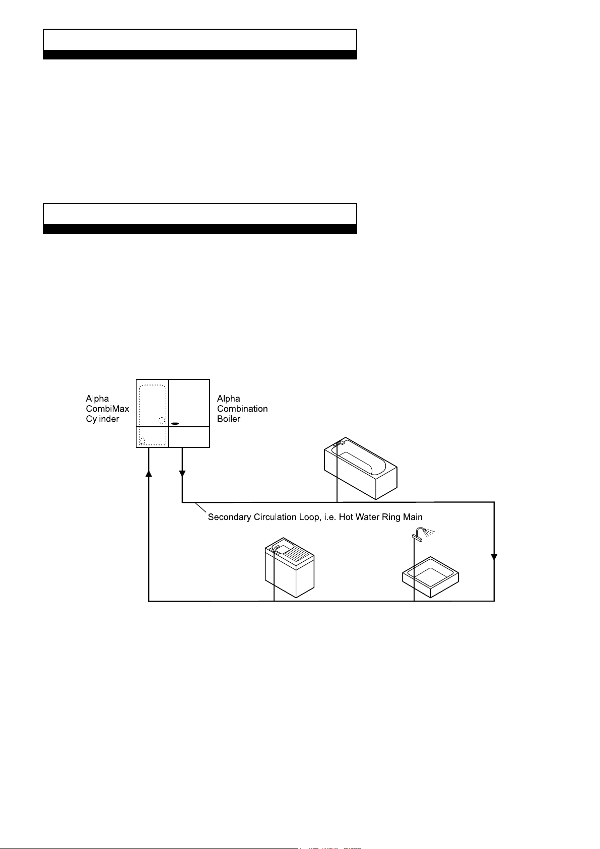
The kits include all pipework and components, i.e. thermostat, non-return valve and flow regulator, necessary to enable a
secondary circulation loop to be connected directly to the CombiMax as shown in Fig. 1.
Alpha CombiMax Secondary Circulation
2
Fig. 1
Page 3
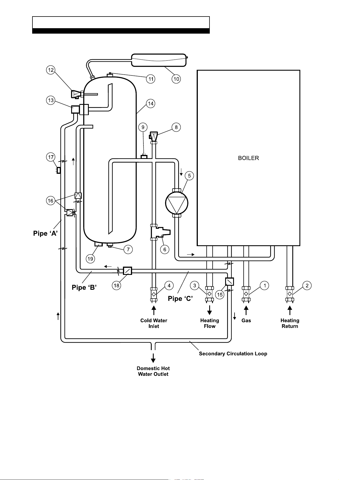
2 SCHEMATIC
COMBIMAX SCHEMATIC - SECONDARY CIRCULATION
1. Gas service cock
2. On/Off valve and filter
3. On/Off valve
4. On/Off valve and filter
5. DHW pump
6. Pressure reducing valve with filter and check valve
7. Drain point
8. DHW expansion relief valve
9. Store thermostat
10. DHW expansion vessel
11. Manual air vent
12. DHW temperature/pressure relief valve
13. DHW outlet thermostat
14. Storage cylinder
15. Boiler flow control regulator
16. Non return valve
17. Recirculation thermostat
18. Restrictor
19. Immersion heater boss
Alpha CombiMax Secondary Circulation
3
Page 4
3 INSTALLATION INFORMATION
3.1 PIPEWORK INSULATION
As hot water is circulated around the loop from the CombiMax cylinder it loses heat. To minimise heat loss it is essential that all
pipework within the circulation loop is adequately insulated. For this reason it is recommended that the secondary loop is in 15 mm
pipe, as larger diameter pipework would increase the heat loss.
3.2 ADDITIONAL EXPANSION VESSEL
The expansion vessel supplied with the CombiMax is sized to suit the CombiMax cylinder and a limited length of pipework only.
Depending on the length of pipework within the secondary loop an additional expansion vessel may be required. If there is insufficient
expansion vessel capacity the expansion relief valve fitted to the cylinder of the CombiMax will operate and discharge.
As a guideline, If the secondary loop is less than 25 metres of 15 mm diameter pipe, an additional expansion vessel should not
be required. If the loop is longer, it is recommended that an additional expansion vessel is fitted in the circuit, where it will be
accessible for inspection and servicing.
Note: The vessel must be acceptable for use on mains water and have a pre-charge of 2.5 bar. A suitable vessel is available
from Alpha Therm, Part No. 0001045.
3.3 DHW CLOCK
Sometimes it may be required to switch off the secondary circulation overnight to avoid unnecessary heat loss and operation of the
appliance. This can be achieved by connecting an external clock to the 'Ext Prog' terminals on the CombiMax terminal block, as
shown in Fig. 4.
3.4 CLEARANCES REQUIRED
These are the same as stated in the installation and Servicing instructions supplied with the CombiMax.
4 INSTALLATION
4.1 UNPACKING
Before installation the CombiMax must be converted for secondary circulation. Carefully unpack the CombiMax box. Check that
you have all the components and place them safely to one side.
Check that the secondary circulation kit is the correct one, i.e. CombiMax 350, Part No. 1000461 or CombiMax 600, Part No.
1000466.
The kit supplied contains the following:-
a. Secondary circulation return pipe, fitted with non-return valve and recirculation thermostat with cable. (Pipe 'A', in
schematic diagram on page 3).
b. Recharge pipe. (Pipe 'B', in schematic diagram on page 3).
c. Secondary circulation flow/boiler return pipe assembly, fitted with restrictor, flow regulator and housing. (Pipe 'C', in
schematic diagram on page 3).
d. Literature, sealing washers and 'Converted to secondary circulation' label (fitted to the thermostat cable).
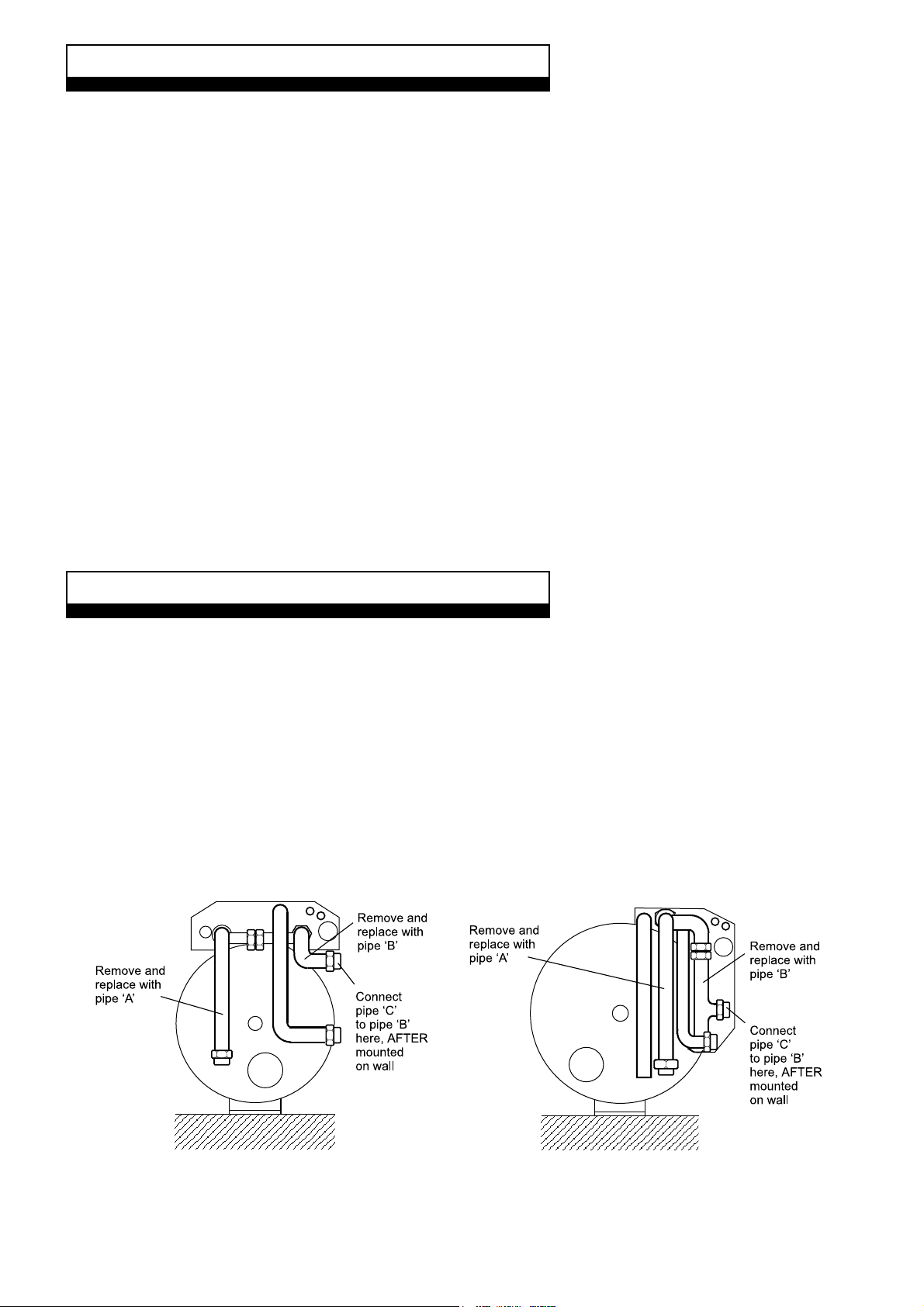
Fig. 2a - CombiMax 350 Fig. 2b - CombiMax 600
Alpha CombiMax Secondary Circulation
4
Page 5
4.2 CONVERT THE COMBIMAX FOR SECONDARY CIRCULATION
The CombiMax must be converted before mounting it on the wall as described below.
1. Place the storage cylinder on its back, then remove and discard the pipework shown in Fig. 2a or 2b.
2. Fit the pipework 'A' and 'B' (section 4.1), supplied in the kit to the storage cylinder in place of the pipework removed, see Fig
2a or 2b. Ensure that all joints have been fitted with the sealing washers supplied.
Note: Pipework 'C' (section 4.1) is used to connect between the boiler outlet and the end of pipe 'B', see Figs. 2a and 3a for
CombiMax 350 and 2b and 3b for CombiMax 600.
3. Connect the cable from the re-circulation thermostat to the CombiMax terminal block by removing the screws securing the
terminal box cover and connecting the wires to terminals 7 and 8. See Fig. 4.
Ensure the leads are passed through the grommetted hole in the fittings plate and secured in the terminal box with the
clamping bush supplied.
Replace the terminal box cover.
4.3 FIT THE COMBIMAX
Mount the CombiMax on the wall as described in sections 4.1 to 4.5 (inclusive) of the Installation instructions supplied with the
Combimax.
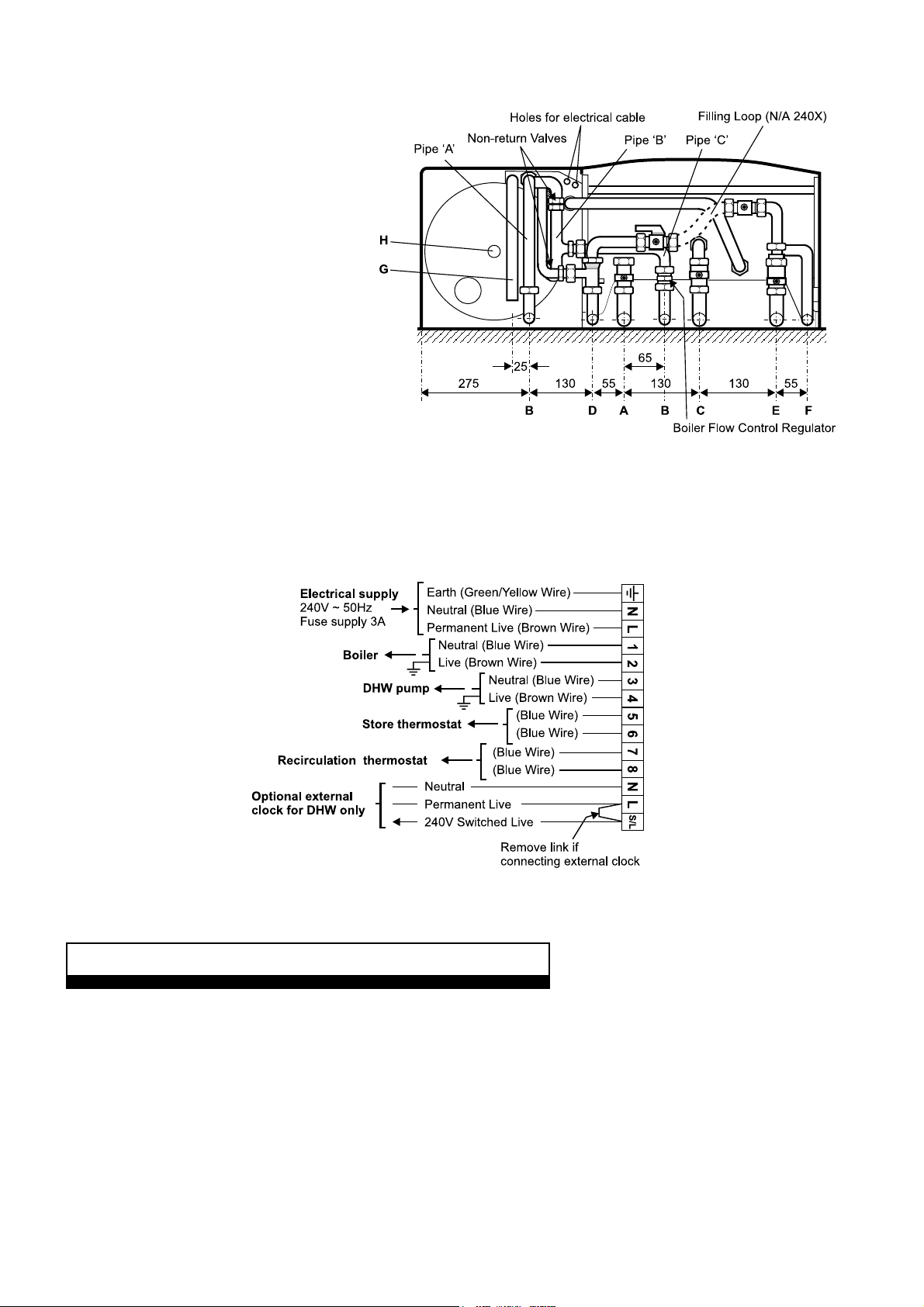
4.4 CONNECT THE PIPEWORK - Fig. 3a or 3b
1. Thoroughly flush out all the water pipework.
Note: Ensure that all the plastic caps have been removed from the boiler connections.
2. Secure all the valves/fittings between the CombiMax and boiler as shown in Fig. 3a (CombiMax 350) or 3b (CombiMax
600). Use the washers supplied and ensure the necessary fittings face the rear wall. Fit the union bends to the valves.
Notes: a. If soldering to the boiler union bends, ensure the bends are not connected to the valves, otherwise the internal
seals may be damaged.
b. Ensure the 22 mm isolating valve with the filter is fitted to the heating return connection as shown in Fig. 3a or 3b.
c. Fit the pressure relief valve connection before the isolating valves.
3. Connect the system pipework to the boiler.
Note: Do not forget that the heating system pressure relief valve discharge pipe must be routed clear of the boiler to a
drain in such a manner that it may be seen, but cannot cause injury to persons or property.
4. Connect the discharge pipework from the temperature/pressure relief and expansion relief valves to the tundish supplied.
Note: This pipework must be installed as recommended in Unvented Hot Water Storage System, section 3.4 of the
CombiMax Installation instructions.
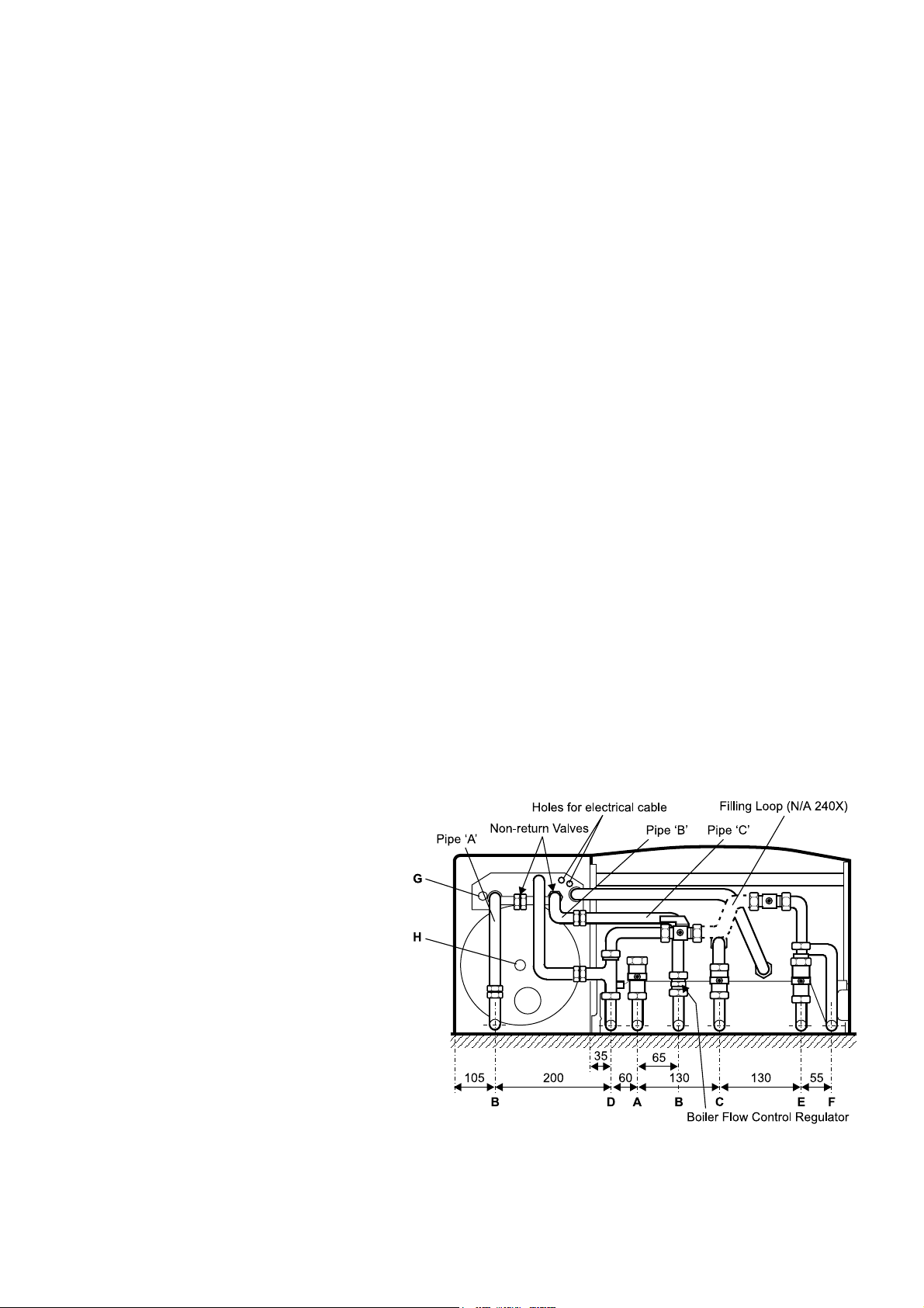
Note: Disconnect the filling loop after filling
the central heating system.
A - Heating flow (22 mm)
B - Secondary circulation loop (15 mm)
C - Gas inlet (22 mm)
D - Cold water mains inlet (15 mm)
E - Heating return (22 mm)
F - Heating pressure relief valve (15 mm)
G - Temperature/pressure expansion relief
discharge pipe
H - Drain point for DHW storage
Note: Both Heating return and Cold water
mains inlet valves contain serviceable filters.
Fig. 3a - CombiMax 350
Alpha CombiMax Secondary Circulation
5
Page 6
Note: Disconnect the filling loop after filling
the central heating system.
A - Heating flow (22 mm)
B - Secondary circulation loop (15 mm)
C - Gas inlet (22 mm)
D - Cold water mains inlet (15 mm)
E - Heating return (22 mm)
F - Heating pressure relief valve (15 mm)
G - Temperature/pressure expansion relief
discharge pipe
H - Drain point for DHW storage
Note: Both Heating return and Cold water
mains inlet valves contain serviceable filters.
Fig. 3b - CombiMax 600
4.5 CONNECT THE MAINS SUPPLY - Fig. 4
Connect the electrical mains supply to the CombiMax and boiler as described in the CombiMax Installation instructions. Also
refer to Fig. 4.
Ensure that all cables are secured with the clamping bushes supplied.
Fig. 4 - CombiMax terminal block
5 COMMISSIONING
Commission the boiler and CombiMax as described in the instructions supplied with both appliances.
Ensure that all the air has been cleared from the domestic hot water pipework by opening all the hot water taps after the
CombiMax store has been fully recharged to its maximum temperature.
The time to reheat the complete system, i.e. the CombiMax store plus the secondary circulation loop, will depend on the length
of the secondary circulation loop.
Alpha CombiMax Secondary Circulation
6
Page 7

6 OPERATION
When a secondary circulation loop is fitted, the CombiMax will still operate as described in section 6 of the instructions supplied
with the CombiMax, except that the DHW pump will not be switched off until both the store thermostat and recirculation
thermostat are satisfied. The recirculation thermostat senses the temperature of the water returning to the store from the
secondary circulation loop and will only switch the pump off when the water in the loop has reached the set temperature of
approximately 56°C.
Domestic hot water always takes priority over central heating. If a demand for hot water is required during a central heating
period, the boiler will automatically switch to the hot water mode until the demand is satisfied, i.e. storage water and circulation
loop have reached the set temperature. This interruption in the central heating is only when the demand for hot water is
present, or when recharging of the circulation loop and store is required.
7 COMPONENT REPLACEMENT
It is the law that any service work must be carried out by a competent person.
Warning: Before replacing any boiler or CombiMax components, isolate the electrical supply and close the boiler gas service cock.
After replacement of any components, check the operation of the CombiMax. Ensure that all the controls are returned to their original settings.
Refer to the instructions supplied with the boiler and CombiMax for full details on replacement of all other components.
7.1 ACCESS
1. To gain access to the CombiMax, remove the bottom two screws securing the CombiMax front casing and lift the casing
up slightly and remove.
2. To gain access to the boiler, refer to the instructions supplied with the boiler.
7.2 DRAINING THE COMBIMAX - See CombiMax Schematic illustration
Isolate the electricity supply.
Remove the front casing as described in section 7.1. Close the mains water inlet valve. Open any hot tap below the level of the store
and open the manual air vent on top of the store. Allow as much water to drain from the store as possible. To drain the remaining
water from the store, open the drain tap at the bottom of the store.
Note: Some water will remain in the components and care must be taken when removing them.
7.3 RECIRCULATION THERMOSTAT - See CombiMax Schematic illustration
1. Gain access as described in section 7.1. Ensure the electricity supply is isolated.
2. Cut and remove the plastic cable tie around the plug and disconnect the plug from the thermostat.
3. Remove the two fixing screws and remove the thermostat from the mains water inlet pipe.
4. Fit the new thermostat and re-assemble in reverse order, fitting a new cable tie around the plug and pipework.
7.4 NON RETURN VALVE - See CombiMax Schematic illustration
1. Drain the CombiMax as described in section 7.2.
2. Undo the unions of the pipe containing the non return valve.
3. Remove the non return valve
4. Re-assemble in reverse order with a new valve and seals.
5. Refill the store as described in section 7.6.
7.5 BOILER FLOW CONTROL REGULATOR - See Fig. 3
1. Drain the CombiMax as described in section 7.2.
2. Refer to Fig. 3 and disconnect the pipework containing the regulator.
3. Remove the regulator from its housing.
4. Re-assemble in reverse order with a new regulator.
5. Refill the store as described in section 7.6.
7.6 REFILL THE DOMESTIC HOT WATER SYSTEM
Open the mains water inlet valve and allow the Combimax store and boiler to fill. When filled, open the manual air vent on the
top of the store (refer to schematic diagram on page 3) until all the air has been vented. Turn on all the hot water taps and allow
water to flow until no air is present. Turn off the taps. Cover all electrical components beneath the CombiMax pump and then
release the pump bleed screw until all the air has been vented. Retighten the screw.
Alpha CombiMax Secondary Circulation
7
Page 8

8 SHORT PARTS LIST
SECONDARY CIRCULATION ONLY
Refer to section 2
Item 17
Item 16
Item 15
Description
Recirculation thermostat
Non-return valve
Boiler flow control regulator
Model
Both
Both
Both
Qty.
1
1
1
Alpha Part No.
0001111K
0001048
0001059
Alpha Therm Limited.
Nepicar House, London Road, Wrotham Heath
Sevenoaks, Kent TN15 7RS
email: info@alphatherm.co.uk
website: www.alpha-innovation.co.uk
Manual compiled and designed by Publications 2000, Tel (01670) 356525
These instructions have been carefully prepared but we reserve the right to
alter the specification at any time in the interest of product improvement.
© Alpha Therm Limited 1999.
Part No. 0001120/2
09/99/D118
 Loading...