


Operator’s Manual
Alpha CFR 1500, CFR 2000,
CFR 2500, and CFR 3000
U N I N T E R R U P T I B L E P O W E R S U P P L I E S
F R O M A L P H A T E C H N O L O G I E S

Operator’s Manual
Alpha
CFR 1500, CFR 2000,
CFR 2500, and CFR 3000
U N I N T E R R U P T I B L E P O W E R S U P P L I E S
IMPORTANT SAFETY INSTRUCTIONS
CONTAINED IN THIS MANUAL
CAUTION
RISK OF ELECTRICAL SHOCK
CAUTION: To reduce the risk of electrical shock, and to
ensure the safe operation of this unit, the following
symbols have been placed throughout the manual.
Where these symbols appear, servicing should be
performed only by qualified personnel.
Dangerous Voltage
A dangerous voltage exists in this area.
Use extreme caution.
Attention
Important operating instructions.
Follow these instructions closely.
WARNING:
To reduce the risk of fire and shock hazards, do not
expose this unit to rain or moisture.
SAVE THESE INSTRUCTIONS
This manual contains important installation and
operating instructions. Keep this manual in a safe
place.
THE ALPHA CFR
IMPORTANT SAFETY PRECAUTIONS
Carefully unpack the unit. Report any shipping damage immediately.
Please read the operators manual. If you have any questions regarding the safe
installation of the unit, contact Alpha Technologies.
The unit should be serviced only by qualified personnel.
The unit contains more than one live circuit. Even though AC is not present at the
input, it may be present at the output.
Always switch the battery circuit breaker to off before connecting or disconnecting an
external battery pack. This greatly reduces the chance of spark.
For units with a detachable AC line cord, connect a dedicated grounding wire (14 AWG/
2.0 MM2) from the ground lug on the back of the unit to an electrical ground point. This
will provide a safety ground connection to the unit and all of its attached equipment,
even when the AC line cord is unplugged.
The connections on the back of this unit are not for use with telephone network
connections.
The standard unit, with line cord and receptacles, may be installed by a non-technical
user.
Units equipped with terminal block input or output connectors, or external battery
packs, must be installed by qualified service personnel in accordance with the following
table:
MODEL TERMINAL BLOCKS TIGHTENING TORQUE
AWG mm
1500-2500 (60Hz) 14 2.0 35 4.0
3000 (60Hz) 12 3.0 35 4.0
2000-3000 (50Hz) 16 1.5 35 4.0
When not in service, the batteries should be charged at least once every three months
to ensure optimum performance and battery life. For standard units, simply plug the
units’ power cord into a wall receptacle and leave it running for one to three days.
The unit should be installed upright in a well ventilated area that is free of dust and
moisture.
Alert Fire or Emergency personnel than an uninterruptible power supply is installed in
the building by placing a notification or warning label on the electrical panel.
When connecting a load to the unit’s rear panel, do not exceed the output rating of the
unit.
2
Inch Newton
Pounds Meters

THE ALPHA CFR
IMPORTANT SAFETY PRECAUTIONS
The CFR 1500-3000 Series units contain sealed, Lead-Acid batteries consisting of:
Four batteries, six cells each, 48 VDC total.
WARNING: Batteries contain high energy and chemical hazards. Carefully read this
manual regarding safe battery handling, maintenance and disposal instructions.
Inspection and replacement should be performed only by qualified personnel.
Wear insulated gloves and eye protection whenever working inside the battery
compartment.
Do not allow live battery wires to contact the unit’s chassis. Shorting battery wires
could result in a fire or possible explosion.
Batteries should be inspected every year for signs of cracking, leaking, or signs of
swelling.
Always replace batteries with those of an identical type and rating. Never install old
or untested batteries.
Avoid using uninsulated tools or other conductive materials when handling batteries
or working inside the unit.
Remove all rings, watches and other jewelry before servicing batteries.
Spent batteries are considered environmentally unsafe. Always recycle batteries..
Verify the voltage requirements of the equipment to be protected (load), the AC input
to the UPS (Line), and the output voltage of the UPS prior to installation.
The utility service panel should be equipped with a circuit breaker that is rated
(Amperage) for use with the UPS
Use proper lifting techniques whenever handling the UPS or an external battery pack.

The Alpha CFR
Table of Contents
The Alpha CFR 1500, CFR 2000, CFR 2500, and CFR 3000
Uninterruptible Power Supplies
1. INTRODUCTION .................................................................1
2. FEATURES .........................................................................5
3. INSTALLATION ..................................................................17
1.1 The Alpha CFR ............................................................1
1.2 The CFR Advantage.....................................................2
1.3 Unpacking and Inspection ............................................4
2.1 A Tour of the CFR .......................................................5
2.2 CFR Front Panel ..........................................................5
2.3 CFR Rear Panel ...........................................................6
2.4 Information Management Options .................................8
Standard Interface Device
Intelligent Interface Device
External Modem
2.5 Communication / Interface Options ......................... 10
RS-232 Monitoring / Control Applications
Rear Panel Connectors
RS-232 Connector
Standard CFR-UPS
Desktop IID
LAN Interface Connector
External IID Connector
External Alarms Connector
EPO Emergency Power OFF Switch
3.1 Pre-Installation ............................................................. 17
Site Preparation
Utility Circuit Breaker
Grounding
Standby Generators
3.2 Connecting the CFR ....................................................18
3.2.1Terminal Block Input and Output ...................................19
3.3 External Battery Pack ...................................................21
3.4 208VAC/240VAC Configurations ..................................22
4. OPERATION .......................................................................25
4.1 Start-up and Test..........................................................25
Manual Self-test
Audible Alarm OFF
Manual Start (No AC Line Power)
Switching OFF the UPS
i

The Alpha CFR
Table of Contents,
4. OPERATION,
4.2 Using the Standard Interface Device.............................28
continued
continued
UPS Powering Up
Output Shutdown Pending
Output Shutdown in Progress
Line Present Operation
Line Failure (AC Input Out of Tolerance)
Line Failure Operation
Line Synchronization
Low Battery Warning
Low Battery Shutdown
Test
Service
Alarm Off Switch
Manual Start / (Hold to Test) Switch
Output Load Display
5. RS-232 TERMINAL COMMUNICATION.............................33
5.1 Remote RS-232 Operation ...........................................33
5.2 RS-232 Menu Selection Icons ...................................... 34
5.3 Remote Terminal Quick Reference ............................... 35
5.4 Menu Commands Overview .........................................36
5.5 System Parameters......................................................37
5.6 Input Parameters .......................................................... 38
5.7 Output Parameters .......................................................38
5.8 Battery Parameters ...................................................... 40
5.9 User Parameters ..........................................................40
5.10 Maintenance Parameters ..............................................45
5.11 Parameter DUMP Command ........................................47
5.12 Event Descriptions ....................................................... 48
5.13 RS-232 Terminal Setup ................................................52
6. MAINTENANCE ..................................................................53
7. SPECIFICATIONS ..............................................................64
8. WARRANTY........................................................................ 66
6.1 CFR Maintenance ........................................................ 53
6.2 Battery Maintenance.....................................................53
6.3 Battery Testing .............................................................54
6.4 Removing the CFR Front Panel and Cover ...................55
6.5 Internal Battery Replacement........................................56
6.6 Troubleshooting Guide ................................................. 59
6.7 Troubleshooting Using The SID ....................................61
6.8 Repair Instructions ....................................................... 63
6.9 Parts and Ordering Instructions .................................... 63
7.1 Specifications ...............................................................64
IMPORTANT:
EMERGENCY SHUTDOWN PROCEDURE ON INSIDE BACK COVER
ii
1. INTRODUCTION
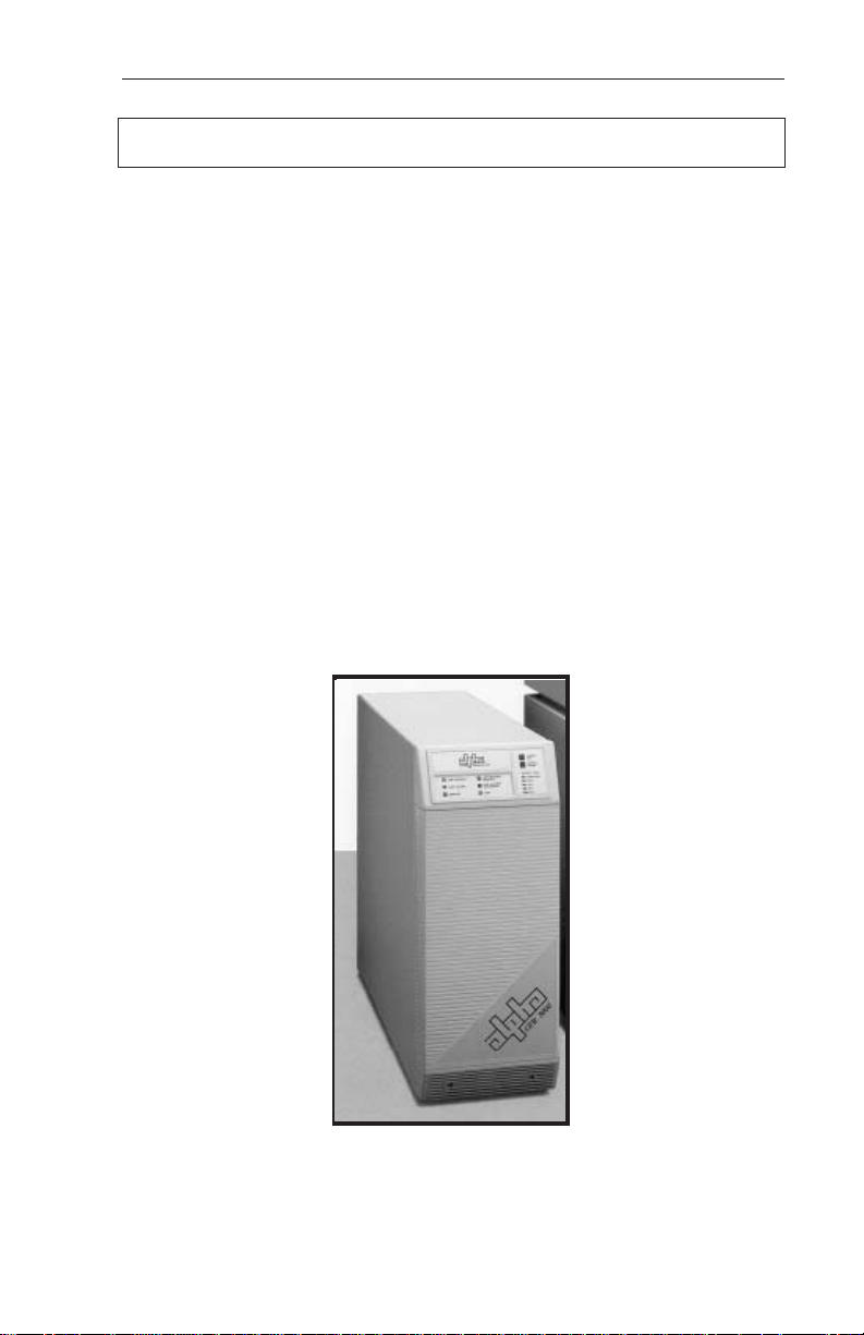
1.1 The Alpha CFR
Congratulations on your purchase of one of the most advanced and intelligent
Controlled Ferroresonant-Uninterruptible Power Supplies (CFR-UPS) in the world! The
Alpha CFR is designed to keep your equipment operating, regardless of the condition
of your utility power. This means that your vital equipment will no longer be affected by
spikes, surges, sags, noise, brownouts, blackouts or other forms of electrical disturbances. Operation is as simple as plugging your equipment into the back of the UPS
and switching on the power.
The CFR provides you with a wide range of power management options using
your choice of interface devices. The Standard Interface Device displays vital UPS
operating parameters, including Alarms, and allows you to manually self-test the UPS.
The Intelligent Interface Device provides you with precise Voltage, Current and
Frequency information, plus maintains an on-going record of all Alarm and Line Failure
Events. As an active center of communication, your CFR can also be interfaced
directly to your computer system to inform you, and your users, of changes in status as
they occur.
With distribution networks and service centers located throughout the world,
Alpha Technologies is here to back you up. From your date of purchase, Alpha
provides complete technical support and prompt, reliable service to ensure that your
CFR-UPS provides you with a lifetime of reliable operation.
The Alpha CFR-UPS provides regulated, current-limited,
output with excellent isolation and noise attenuation.
1

1. INTRODUCTION
1.2 The CFR Advantage
Power protection devices can be judged by the type and quality of power they
provide. Alpha CFR Uninterruptible Power Supplies provide continuous, conditioned
“computer-grade” AC power to electronic equipment such as Computer Systems,
Point of Sale Terminals, Process Controls, Telecommunications, Cable TV Headend,
Broadband LAN, Manufacturing Control Systems, Critical Care and Hospital Lab
Equipment.
Alpha's proven design virtually eliminates surges and spikes. The Alpha CFR
UPS provides spike attenuation of 2000 to 1 and meets the requirements of IEEE 587
/ ANSI 62.41.
Unlike many standby power systems which regulate output voltage
only when operating from their battery backup, the Alpha CFR UPS
constantly maintains +1% output regulation without using precious battery power.
Even with input voltage fluctuations as great as +10% or -25%, the output remains
constant, regardless of load.
Electromagnetic and Radio Frequency Interference (EMI and RFI) can damage
semiconductors and have devastating effects on critical data. The CFR UPS input is
totally isolated
ference. Measured in decibels (dB) of attenuation, Alpha's CFR achieves up to 120
dB common mode, and 60 dB normal mode.
Alpha's EBP Series External Battery Packs allow you to greatly extend your
backup capabilities and power through long utility outages. Completely self-contained
and pre-wired, simply plug the EBP cabinet into your CFR and forget about it. EBP
Series External Battery Packs can also be ordered with an optional, external charger
to greatly reduce battery recharge times.
ADVANCED POWER PROTECTION TECHNOLOGY
SURGE AND SPIKE REJECTION
REGULATION
ISOLATION
from the output to provide maximum protection from this type of inter-
EXTENDED BACKUP CAPABILITY
2

1. INTRODUCTION
1.2 The CFR Advantage,
COMMUNICATIONS AND INTELLIGENCE
Alpha's interchangeable Standard Interface Device and Intelligent Interface
Device allow your CFR to become an active part of your communications network
providing you with a variety of interface options.
SELF-TEST CAPABILITIES
The CFR has a built-in, self-test function that checks all critical areas of the
UPS, including the batteries, to ensure optimum performance. Whenever a problem
is detected, the UPS lights a “Service” indicator. Self-test is extremely useful during
troubleshooting and maintenance.
PRECISE LOAD & OVERLOAD INFORMATION
The Alpha CFR provides vital load information to eliminate guess work associated with matching the appropriate load to your unit. The Alpha CFR displays the
existing load and, whenever the load exceeds the rated output, an "Overload"
indicator is illuminated.
The CFR UPS is equipped with a frequency sense circuit, along with a constant
slew frequency synchronization circuit, to provide trouble-free operation with most
standby generators.
Designed to meet or exceed the safety standards established by UL, CSA and
VDE, the Alpha CFR UPS is one of the safest, most reliable and versatile
uninterruptible power supplies available. Our commitment to safety and quality
engineering has not only established industry-wide safety standards, but has earned
Alpha Technologies international recognition as a leader in power protection
equipment.
continued
GENERATOR READY
SAFETY
3

1. INTRODUCTION
1.3 Unpacking and Inspection
Carefully remove the UPS from its shipping container. Inspect the contents. If
items appear to be damaged or missing, contact Alpha Technologies and the shipping
company immediately. Most shipping companies have only a short claim period. Make
sure the following items have been included:
1. CFR Series UPS with AC Line Cord
2. Operator's Manual
3. Any other ordered options
SAVE THE ORIGINAL SHIPPING CONTAINER.
In the event the UPS needs to be returned for service, it should be packaged in
its original shipping container. If the original container is not available, make sure that
the unit is packed with at least three inches of shock-absorbing material to prevent
shipping damage. NOTE: Do not use popcorn-type material. Alpha Technologies is
not responsible for damage caused by the improper packaging of returned units.
PLEASE READ THE OPERATOR'S MANUAL.
Become familiar with the UPS front and rear panels. Review the drawings and
illustrations before proceeding with the UPS installation. If you have questions
regarding the safe installation or operation of the UPS, contact Alpha Technologies.
COMPLETE THE FOLLOWING FOR YOUR RECORDS:
Model #
Serial #
Options
Purchase date
THIS UNIT WAS PURCHASED FROM:
Dealer name
City
State/Province
Zip/Postal Code
Country
Telephone #
4
2. FEATURES
2.1 A Tour of the CFR
The Alpha CFR is designed to be easy to use and extremely flexible. The CFR’s
interchangeable front panel interface devices provide you with a wide range of
information management options. The rear panel accepts a variety of connectors and
receptacle plates to facilitate your most demanding communication and powering
needs.
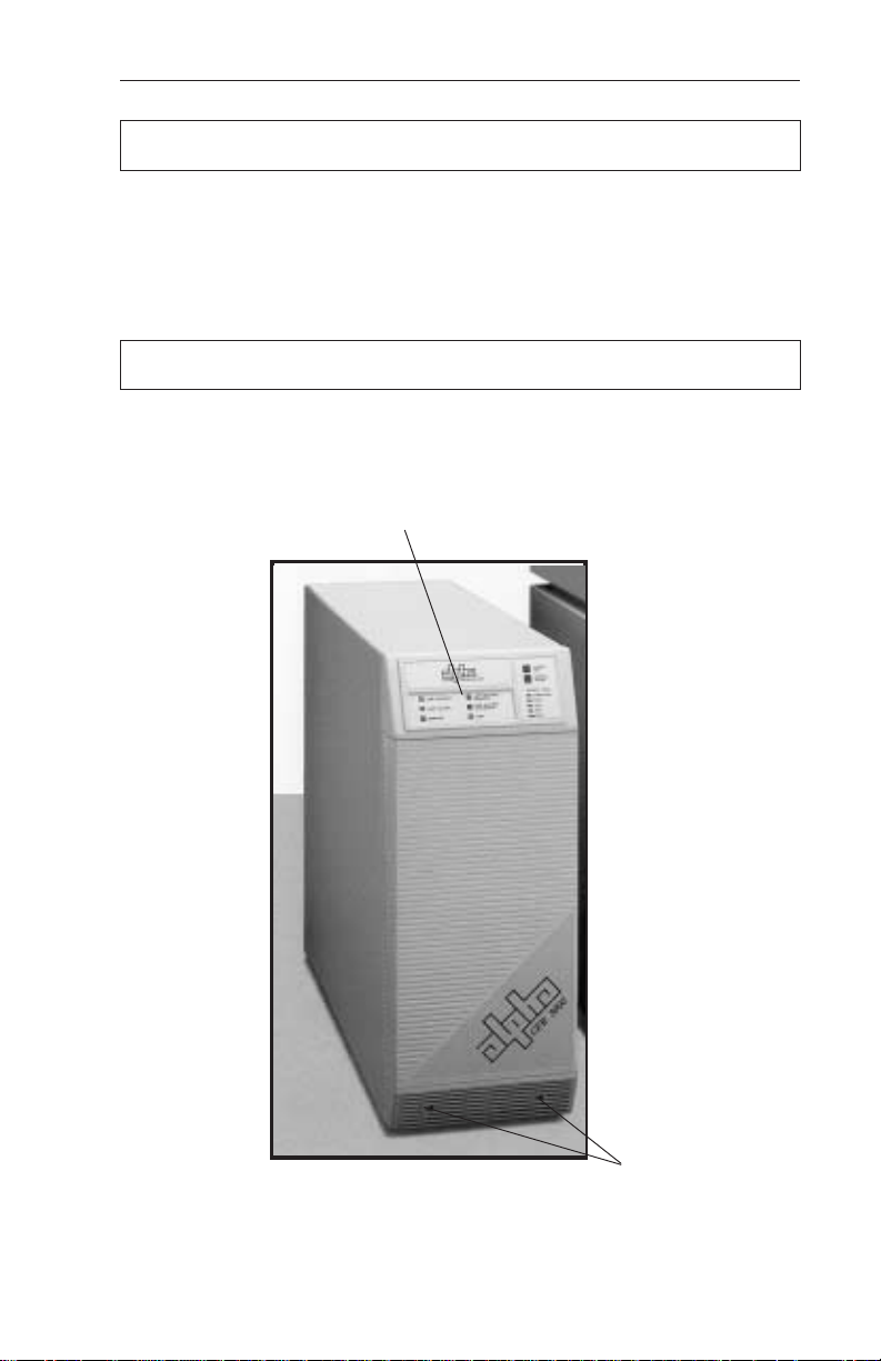
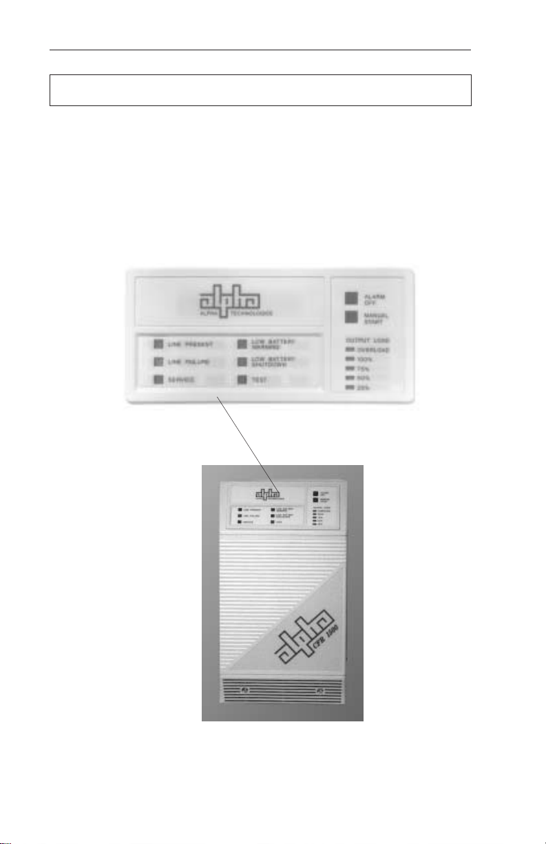
2.2 The CFR Front Panel
The CFR front panel comes equipped with a Standard Interface Device (SID), or
an optional Intelligent Interface Device (IID), to display vital UPS operating parameters.
The front panel can be easily removed for service or battery access by loosening the
two screws located in the lower grill.
Standard Interface Device
Fig.1
CFR Front Panel
5
Panel Screws
2. FEATURES
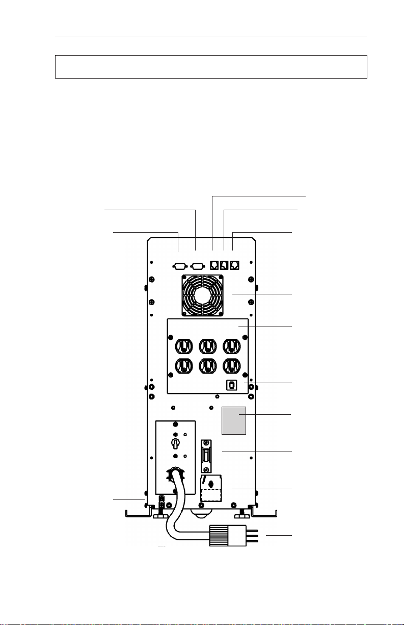
2.3 CFR Rear Panel
1. AC LINE Cord
The UPS is equipped with a standard, grounded AC line cord.
2. EXTERNAL BATTERY Connector
The connector accepts a standard plug from the EBP Series Battery Pack.
Extending backup time is as simple as plugging in the battery pack.
3. BATTERY Circuit Breaker
The battery breaker protects the DC circuit. When the UPS is not in service, the
breaker should be switched OFF to preserve the batteries in the UPS and in the EBP
Series Battery Pack, if installed (see section 4.1 “UPS Shutdown”).
4. External Ground Lug (Single Point Ground)
The external ground lug provides a single point connection for optimum grounding
protection. Always refer to your local electrical codes for prescribed grounding
practices.
5. UPS Nameplate Label
The nameplate label contains valuable information relating to the UPS. Always
verify input voltage and frequency (i.e., 120 VAC / 60 Hz) before use.
6. RS-232 Serial Connector (DE-9 Female Connector)*
The standard RS-232 serial interface allows for connection to a host computer/
dumb terminal for remote monitoring, control and calibration of the UPS. Use a straight
through serial cable to connect the UPS to the computer.
7. LAN Interface Connector (DE-9 Female Connector)
The LAN Interface connector provides dry contact status monitoring and output
shutdown capability on a DE-9 female connector and is used by basic UPS monitoring
software for orderly shutdown of computer networks.
8. Modem Connection
Available as an option on 60Hz Models only.
9. External IID Connector (MMJ Connector)*
This connector is used for the optional desktop Intelligent Interface Device (IID) for
remote monitoring and control of the UPS (up to 2000 ft.).
NOTE: This port is disabled by the factory unless an internal IID is installed.
10. External Alarms Connector (RJ-45 Connector)
This provides dry contact closure alarm status on a RJ-45 (center keyed)
connector, indicating LINE FAIL and LOW BATTERY WARNING.
*NOTE: With the SID installed in the UPS, either the External IID port
the RS-232 port can be activated. The factory default is set for RS-232
operation. With the internal IID option installed in the UPS
active.
6
both
ports are
or
2. FEATURES
2.3 CFR Rear Panel
11. Exhaust Fan
The UPS contains a rear panel exhaust fan to ensure maximum cooling protection
during all modes of operation.
12. OUTPUT Receptacle Plate
The load (equipment to be protected) connects to the rear panel output
receptacles. Styles vary depending upon country, frequency and voltage.
13. AC OUTPUT Circuit Breaker
The resettable breaker provides addional output protection to the load.
8
7
9
6
10
11
12
13
5
3
2
4
1
CFR 1500, CFR 2000, CFR 2500, and CFR 3000 Rear Panel
Fig. 2
7
2. FEATURES
2.4 Information Management Options
Standard Interface Device
The Standard Interface Device provides you with vital UPS operating parameters
from front panel LEDs (see section 4.2). The Standard Interface also has a load
indicator to help you determine precise loading on your UPS, plus Manual Start and
Alarm Off switches. To ensure optimum backup performance, the Standard Interface
comes with a self-test feature which lights the “Service” LED whenever a problem is
detected.
CFR Front Panel with Standard Interface Device
Fig. 3
8
2. FEATURES
2.4 Information Management Options,
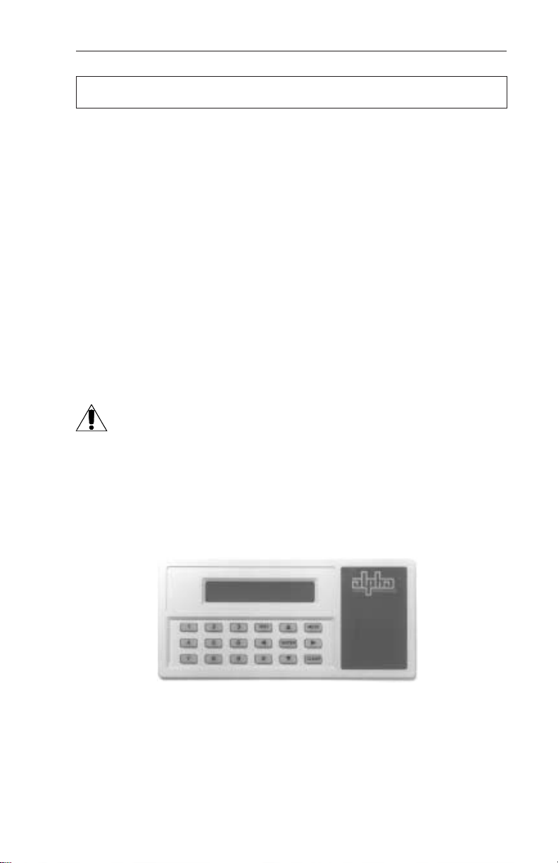
Intelligent Interface Device (optional)
The Intelligent Interface Device (IID) option is available either as a replacement
of the Standard Interface Device (SID) or as a desktop unit for remotely accessing
the unit (up to 2000 ft.). The desktop unit comes with an optional modem for
accessing the UPS information via a telephone line. The IID front panel provides
precise UPS information and guides you through the various menu options which
include Ambient Battery Temperature, Input Voltage and Current, Line Frequency,
Output Voltage and Current, Power in Watts, Power Factor, Battery Voltage, Charger
Status, and more. The History Log maintains an on-going record of UPS alarms and
power anomalies by time, date and type of occurrence. Whenever a UPS alarm
condition occurs, such as Line Failure, Low Battery Warning, Low Battery Shutdown
or Service, it is displayed by the front panel indicators and recorded in the History
Log.
External Modem (option available on 60Hz models only)
The optional modem that comes with the desktop IID provides access to the unit
via a phone line. Service personal can dial up the unit to remotely monitor, control,
and calibrate the unit. On specified alarm conditions, the unit can dial an emergency
number to notify the system manager via modem of the alarm. The modem option
may also be used to page service personnel on critical alarm conditions.
For further information on operation and installation of the IID, please
refer to its operator’s manual “Information Management Using the
Intelligent Interface Device.”
continued
Intelligent Interface Device
Fig. 4
9

2. FEATURES
2.5 Communication / Interface Options
The CFR is equipped with four rear panel jacks for communication and remote
interfaces: RS-232 Serial data; LAN Interface; External IID and External Alarms.
Units with the external modem option have a fifth connector for modem connection.
NOTE: With the SID installed in the UPS, either the External IID port
the RS-232 port can be activated. The factory default is set for RS-232
operation. With the internal IID option installed in the UPS
active.
RS-232 Monitoring / Control Applications
The Alpha CFR-UPS provides a standard RS-232 serial port on a DE-9 female
connector. This port may be used to monitor and control the CFR using 1) ASCII
terminals, 2) UPS monitoring software and 3) SNMP agent devices.
You may use the serial port to interface with a dumb terminal or a personal
computer (running a terminal emulation software) to monitor, control, and calibrate
the CFR. All you need is a standard off-the-shelf RS-232 cable (straight through)
and a terminal. Refer to section 5 “RS-232 TERMINAL COMMUNICATION” for
more information.
You may also use the RS-232 serial port to communicate with the intelligent
UPS monitoring software running on a host computer or a SNMP agent device
connected to your LAN network. Alpha Technologies provides the “AlphaNet C”
family of UPS monitoring software and SNMP agents to manage your network
requirements. You can use the “AlphaNet C shutdown software” to monitor the
CFR in a network environment and to perform an orderly system shutdown when
the battery becomes low (during extended line fail situations). AlphaNet C
shutdown software informs all workstations of pending power failures and
shutdowns and in multi-server networks, AlphaNet can shutdown other servers in
the network as well as the workstations. For a full description of the features and
capabilities of AlphaNet C shutdown software, refer to its user’s manual or contact
Alpha Technologies. AlphaNet C is available for all major network platforms and
operating systems — Novell Netware, SCO Unix, IBM OS/2, IBM AIX, Sun Solaris,
Hewlett-Packard HP-UX (DAT), and Digital Equipment (OS/F, VMS, and DECNET).
both
or
ports are
Alpha Technologies also provides the “AlphaNet CS SNMP Agent Device” to
monitor and control the CFR using the SNMP protocol. This provides an interface
between the CFR and your network environment and allows you to use your
Network Management Station (NMS) to monitor and control the CFR. To obtain
detailed information on SNMP management solutions for your CFR refer to
AlphaNet CS SNMP Agent User’s Manual
or contact Alpha Technologies.
10
2. FEATURES
2.5 Communication / Interface Options,
continued
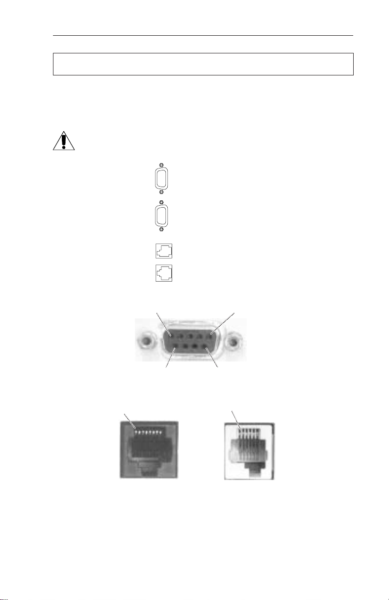
Rear Panel Connectors:
Below are the various communication connectors as they appear on the back of
the CFR-UPS. The photographs show the pin numbering for the different connector
types.
NOTE: Use only fully shielded cables to make connections to any of the
DE-9 connectors (RS-232 port or LAN interface).
RS-232 Serial Connector
LAN Interface Connector
External IID Connector
External Alarms Connector
Pin 1Pin 5
Pin 6 Pin 9
DE-9 Connector (RS-232 and LAN)
Pin 1 Pin 1
RJ-45
(External Alarms)
MMJ
(External IID)
Fig. 5
CFR-UPS Connector Identification and Pin-out
11
2. FEATURES
2.5 Communication / Interface Options,
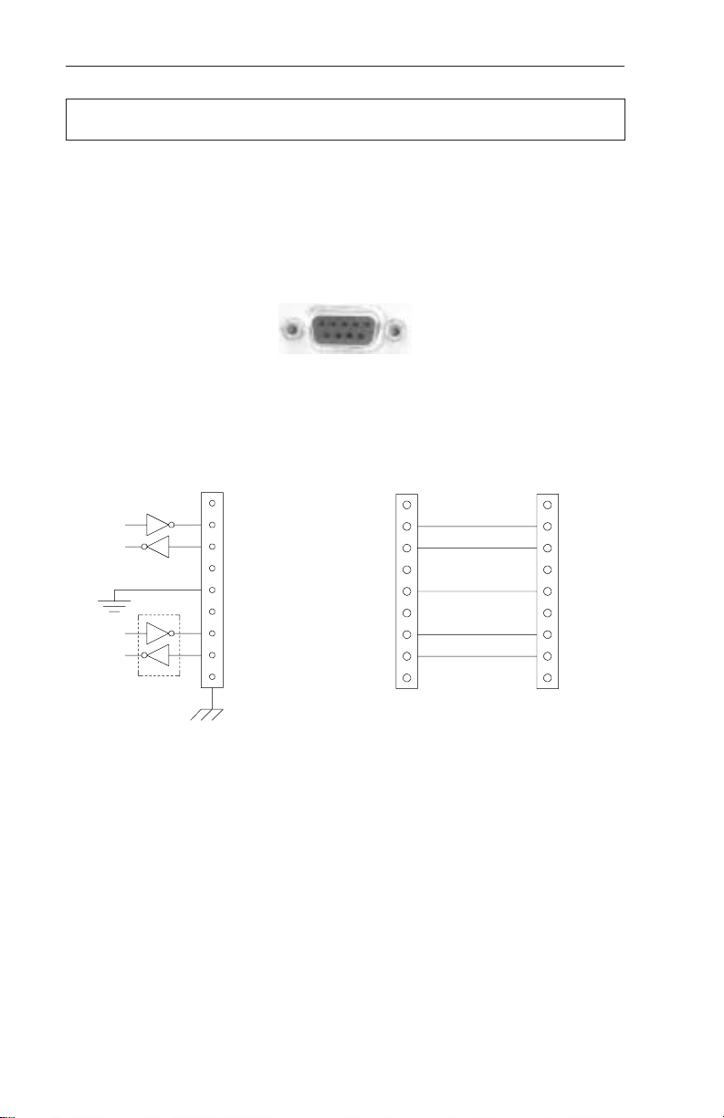
RS-232 Connector:
The connection/specifications for the RS-232 serial port vary depending on the
installed interface device (i.e., SID or IID option).
RS-232 connection for the standard CFR-UPS (with SID or internal IID display)
The standard CFR-UPS configuration with SID or internal IID connects to a
computer or terminal using a standard straight-through RS-232 cable.
CFR-UPS RS-232 Connector
1
2 Tx
3 Rx
4
5 Gnd
6
7 RTS*
8CTS*
9
Fig. 6
1
2
3
4
5
6
7
8
9
continued
1
2
3
4
5
6
7
8
9
Internal CFR connections
*IID Only (Not used with SID)
Communication Settings with IID:
Baud Rate: 300 to 9600
Parity: None, Even, or Odd
Stop Bits: 1 or 2
Data Bits: 7 or 8
Handshaking: RTS/CTS
RS-232 cable to computer or terminal
Use standard straight through type
Communication Settings with SID:
Baud Rate: 1200
Parity: None
Stop Bits: One
Data Bits: 8
Handshaking: XON / OFF
12
2. FEATURES
2.5 Communication / Interface Options,
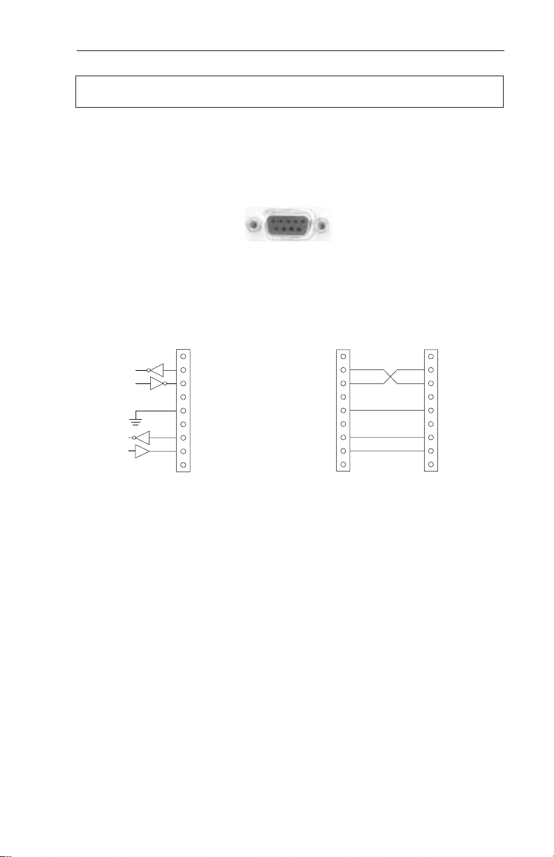
RS-232 Connections with desktop IID:
With the desktop IID the cable connecting the computer or terminal to the UPS
is a nonstandard type.
Fig. 7
CFR-UPS RS-232 Connector
1
2 Tx
3 Rx
4
5 Gnd
6
7 RTS
8 CTS
9
Internal CFR connections
continued
1
2
3
4
5
6
7
8
9
RS-232 cable to
computer or terminal
1
2
3
4
5
6
7
8
9
For the desktop IID use a
nonstandard cable type
Communication Settings with IID:
Baud Rate: 300 to 9600
Parity: None, Even, or Odd
Stop Bits: 1 or 2
Data Bits: 7 or 8
Handshaking: RTS/CTS
13
2. FEATURES
2.5 Communication / Interface Options,
continued
LAN Interface Connector
The Alpha CFR-UPS provides a LAN interface port on a DE-9 female connector.
This port may be used to monitor the status of the UPS and shutdown the output
using basic UPS monitoring and shutdown software.
Two dry contacts are provided to indicate LINE FAIL and LOW BATTERY status
information. The port also accepts a dry contact input or an RS-232 level input to
shutdown the UPS output. The shutdown delay, duration, and recovery modes can
be configured using the RS-232 ASCII terminal commands (see section 5 “RS-232
Terminal Communication”). This port has the following pin out:
1
2 LINE FAIL
3
4 COMMON
5 LOW BATTERY
6 OUTPUT SHUTDOWN
7 GND
8 +12VDC, 5mA max.
9
Pin out: (DE-9 connector), Female
Fig. 8
Using basic UPS monitoring software you can monitor and shutdown the CFR
through this port. In network applications, your UPS monitoring software can perform
an orderly shutdown on the network. Basic UPS monitoring software is provided as
part of many operating systems and can also be purchased from third party vendors.
Alpha Technologies “AlphaNet C shutdown software” can also operate in the basic
mode to shutdown the CFR before its battery reserve is exhausted. Refer to
AlphaNet C Shutdown Software User’s Manual
or contact Alpha Technologies for
more information.
14
2. FEATURES
2.5 Communication / Interface Options,
External IID Connector
The external IID connector provides an interface for the optional desktop
Intelligent Interface Device (IID). This allows the CFR to be remotely monitored and
controlled from up to 2,000 feet away. The port uses a proprietary RS-485 protocol
and has the following pin out:
Pin 1
1: +12V DC (unreg) 4: RS-485 Negative
2: +12V DC (unreg) 5: GND
3: RS-485 Positive 6: GND
Fig. 9
Pin out: (MMJ connector, offset key)
Modem (optional configuration with Intelligent Interface Device; available on
60 Hz models only)
When the CFR UPS is equipped with an Intelligent Interface Device (IID), an
internal modem can be installed to provide long-range communications. A standard
modular telephone cable is used to connect the CFR modem jack to the wall jack.
For further information, refer to the Intelligent Interface Device manual.
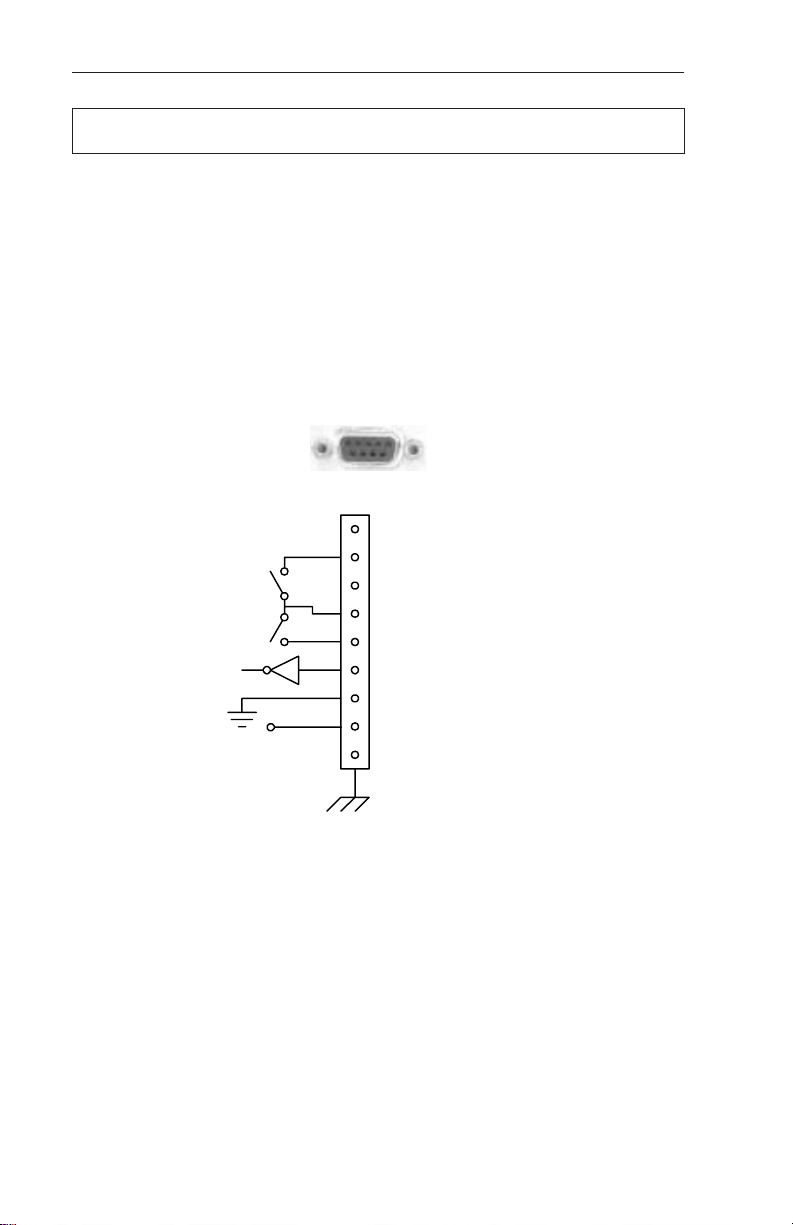
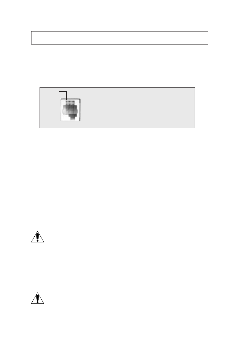
External Alarms Connector
The external alarms connector provides two contact closures to indicate LINE
FAIL and LOW BATTERY alarms.
continued
EPO (Emergency Power OFF) Switch
Pins 7 and 8 of the ALARM INTERFACE connector provide EMERGENCY
POWER OFF contacts. A switch contact can be hard-wired to the UPS to
completely shut down the system in the event of an emergency, such as a
fire.
In an emergency, the switch must be depressed (shorted) for at least 1.5
seconds. The UPS will shut down approximately 2 seconds after the signal is
recognized. The switch, connected to pins 7 and 8, must be electrically isolated (up
to 1500 VAC isolation is recommended). A system shut down in this manner will
open the BATTERY circuit breaker.
CAUTION: When the EPO switch is activated, the AC line connected to the
UPS input may still be energized. To completely remove the power from the
building, the MAIN AC line breaker in the building must be switched OFF.
Consult your national and local electrical codes for further information.
(Factory Installed Option)
15
2. FEATURES
2.5 Communication / Interface Options,
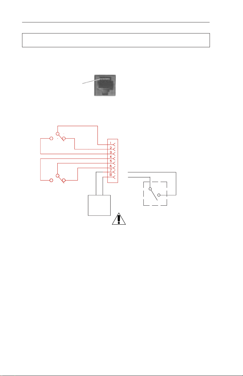
External Alarms Connector,
Pin out: (RJ-45 connector, centered key)
Low Battery
Warning
Line Failure
N.C. = Normally Closed
N.O. = Normally Open
Line Present
N.C.
N.C.
Battery OK
Pin 1
continued
EPO
Emergency
Power OFF
Option
continued
Pin out: (RJ-45 connector, Female)
1. LINE FAIL, COM contact
2. LINE FAIL, N. C. contact
3. LINE FAIL, N. O. contact
4. LOW BATTERY, N. O. contacts
5. LOW BATTERY, COM contacts
6. LOW BATTERY, N. C. contacts
7.
8.
N.O.
Emergency UPS Shutdown
Switch (Wall Mounted).
NOTE: Cable length must not
exceed 100 feet. Use twisted
or shielded wire.
External Alarms Connector Pin-out
(with factory installed EPO Switch Option)
16

3. INSTALLATION
3.1 Pre-Installation
Do not connect the UPS to a line conditioner, isolation transformer or any
similar type of device. Damage to the UPS and the line conditioning
equipment can occur.
Site Preparation
The UPS should be installed upright in a well-ventilated, dust free environment.
The weight of the UPS, especially if it has an optional battery pack, is quite heavy (see
specifications). Do not place the unit on any surface unable to fully support its weight.
The CFR 3000 has two leveling feet at the back panel which should be used to
stabilize the unit.
Utility Circuit Breaker
circuit breaker. Breaker size can be determined by adding 15% to the maximum input
current of the unit (see specifications). For example, the CFR2000 draws 14.6 Amps
of current when configured at 120VAC. By adding 15%, the number becomes 16.8
Amps. In this case, a standard 20 Amp circuit breaker is suitable for use.
Grounding
derived power source"), proper grounding is critical. Many older facilities may have an
electrical system that is incapable of supporting this type of grounding requirement. To
ensure optimum performance from your UPS, always install a hardwired ground. A
qualified electrician should also inspect the existing wiring in the building prior to
installation to verify proper grounding.
The UPS should be installed on a dedicated circuit with a properly sized
Since the CFR UPS bonds output neutral to ground (qualifying it as a "separately-
Standby Generators
The CFR is equipped with a frequency sense circuit, along with a constant slew
frequency synchronization circuit, to optimize operation with most standby generators.
Prior to installation, compare the output voltage of the generator to the voltage
requirements of the UPS (see CFR nameplate label). If the UPS requires 240 VAC
input and the generator produces only 208 VAC, it will cause the UPS to run
continuously off of battery power. This would discharge the UPS batteries and cause
the output load to fail.
Alpha Technologies recommends using a generator equipped with an electronic
speed and voltage control. If a generator equipped with a mechanical governor "speed
control" is used, this could also cause the UPS to run continuously in LINE FAILURE
mode due to the unstable frequency of the generator.
The generator should also produce less than 10% voltage THD. Generators with
a higher THD rating may cause the CFR UPS to switch to LINE FAILURE mode, and
switch to battery operation, as the generator output would be sensed as a noisy utility.
17

3. INSTALLATION
3.2 Connecting the CFR (Plug & Receptacle)
1. Connect a dedicated ground wire from the GROUND lug on the back of
the CFR to an electrical ground point (i.e., wall receptacle gound or a
copper water pipe). The wire size must be at least 12 AWG (3mm2).
NOTE: Most electrical codes require this type of ground connection in
case the AC line power cord is disconnected from the wall. Always
consult your local electrical code to ensure prescribed grounding
practices.
2. Connect the CFR's AC power cord to the wall receptacle.
3. If using an external battery pack, plug its connector into the rear panel of
the UPS (see section 3.3).
4. Start and test the UPS without the load connected (see section 4.1).
After testing, switch the unit OFF before connecting the load.
5. Plug the equipment to be protected into the UPS rear panel receptacles.
NOTE: The load should be switched OFF prior to connection.
The UPS utilizes a transformer to provide excellent isolation and voltage regulation.
During normal operation, the UPS will be warm to the touch, but not hot enough to
burn. The transformers have been coated with a laquer finish which may produce a
slight, nontoxic odor during the first several weeks of operation.
WARNING
The UPS generates EMR (Electromagnetic Radiation). Keep all sensitive magnetic media,
such as credit cards, floppy disks, magnetic key cards, recording tape, etc., away from this
unit.
18

3. INSTALLATION
3.2.1 Terminal Block Input and Output
CAUTION: Installation and wiring should be performed by qualified service personnel
in accordance with applicable electrical codes. Verify that the main utility panel is
switched OFF before proceeding. Mark all circuit breakers supplying the UPS.
1. Connect the input and output wires (Refer to the table below for
recommended wire sizes and tightening torques.)
MODEL TERMINAL BLOCKS TIGHTENING TORQUE
AWG mm
1500-2500 (60Hz) 14 2.0 35 4.0
3000 (60Hz) 12 3.0 3 5 4.0
2000-3000 (50Hz) 16 1.5 35 4.0
2
Inch Newton
Pounds Meters
GROUND Lug
AC LINE
Power Cord
Fig. 10
CFR 1500, CFR 2000, CFR 2500,
and CFR 3000 Rear Panels
19
UPS
Receptacle
AC LINE
Circuit Breaker
BATTERY
Circuit Breaker
Leveling Feet
(CFR 3000 only)

3. INSTALLATION
3.2.1 Terminal Block Input and Output Wiring
CFR 1500, CFR 2000, CFR 2500 and CFR 3000
Frequency Voltag e* L N
60Hz 120VAC 120VAC Neutral
50Hz 230VAC 230VAC Neutral
60Hz 208VAC Ø1 Ø2
60Hz 240VAC Ø1 Ø2
WARNING: Overcurent protection for the AC output circuit must be
provided at the time of installation
CFR 1500, CFR 2000, CFR 2500 and CFR 3000
Frequency Volta ges* L1 N L2**
60Hz 120 / 208 VAC 120VAC Neutral 208VAC
60Hz 120 / 240 VAC 120VAC Neutral 240VAC
50Hz 230VAC Not Used Neutral 230VAC
Terminal Block Input
Terminal Block output
* CAUTION: Refer to the nameplate voltage and frequency ratings
affixed to the unit. This power supply was wired for this particular
voltage configuration when it was shipped from the factory.
**Units shipped as 60Hz, single 120V output, do not use L2.
20

3. INSTALLATION
3.3 External Battery Pack
The CFR is designed so that battery backup time can be greatly extended simply
by plugging the EBP 48 External Battery Pack to the back of the UPS. Battery packs
are completely self-contained.
Unit Rating Run Time* for CFR Module
1500 2000 2500 3000
EBP 48A 33 Ah 1.5hrs 1.0hrs .75hrs 1.1hrs
EBP 48E 88 Ah 3.5hrs 2.4hrs 1.8hrs 2.2hrs
*Battery run times are calculated at typical load (80%) and represent the total time of the CFR internal batteries and EBP
battery pack.
1. Switch the CFR's BATTERY circuit breaker OFF.
2. Locate the EXTERNAL battery connector on the rear panel of the UPS
and remove the Phillips screw #1 and loosen Phillips screw #2.
3. Slide the cover plate to the left and insert the battery pack’s connector
into the UPS. Secure the connector to the UPS using the Phillips screw #1.
4. Switch the EBP and CFR “BATTERY” breakers ON and test the unit
for proper operation.
BATTERY
Circuit Breaker
External Battery
Connector
Phillips Screws
Fig. 11
CFR 1500, CFR2000, CFR 2500, and CFR 3000 with EBP External Battery Packs
21

3. INSTALLATION
3.4 208 VAC vs 240 VAC (60 Hz) Configurations
In North America, there are only two recognized supply voltages: 208 VAC
(most commonly used in industrial, commercial, and office areas); and 2 0 VAC
(most commonly used in residential areas). 120 VAC can be derived from both 208
and 2 0 VAC services.
NOTE: The terms 220 VAC and 230 VAC are actually local terminology,
referring to 2 0 VAC service.
This unit complies with NEC/CEC for center tapped neutral bond to ground.
VOLTAGE POTENTIAL
UPS units equipped for 208 VAC output operation have a 208 VAC potential
between
120 VAC potential appears
further information, contact Alpha for assistance.
LOAD SHARING
(either to the output receptacle or terminal block), care must be taken to ensure that
the total power drawn does not exceed the maximum rating of the unit. For
Terminal block output, wherever possible, connect all 120V loads to L1 (not L2). If
120 V loads are connected to L2, do not exceed the current listed in Table 3. .1.
L1 and L2. In comparison, when the UPS is wired for 2 0 VAC output, a
between
The transformer used in the CFR UPS is equipped with an additional
tap (L1 to N) for 120 VAC operation. This provides a dual output volt
age potential of 208 VAC and 120 VAC. Note: In this configuration,
the voltage potential between L2 (208 VAC) and Neutral is only
VAC
. Refer to the illustration below.
If several pieces of equipment are connected to the 120 V output of the CFR
Model Maximum current on L2
CFR 1500 7.2A
CFR 2000 9.6A
CFR 2500 12.0A
CFR 3000 1.A
IMPORTANT:
L2 and Neutral, and L1 and Neutral. For
88
Table 3.4.1
22

3. INSTALLATION
3.4 208 VAC vs 240 VAC (60 Hz) Configurations
Since loads are shared, it is possible to exceed the rated maximum output
current of one of the transformer windings, without actually exceeding the rated
output current of the CFR-UPS. Therefore, careful consideration must be given as to
how the loads connected to the CFR are to be divided.
One way to ensure that the current drawn from each half of the transformer
windings is within the CFR’s specifications would be to measure the actual total load
being drawn. This can be accomplished using a clip-on current probe (refer to the
following drawings). The total current being drawn by L1 is a combination of the
current draw from A + B + C, (where A is the total current draw from each 120V load
connected to the receptacle, B is the total current draw from each 240V load
connected to the receptacle, and C is the total current draw from the L1 side of the
terminal block). The total of these currents must not exceed the rated output current
for each winding of the CFR. The same is true for the L2 winding of the transformer.
You can measure these currents at points B and D, (where B is the total current draw
from each 240V load connected to the receptacle, and D is the total current draw
from the L2 side of the terminal block).
NOTE: If using the SID or IID to measure the output currents, you must
calculate the Output current for L1 as described below.
If the CFR has a
of the CFR connected to a PC, as OUTPUT CURRENT 1 and OUTPUT CURRENT 2
(see section 5.6, Output Parameters). The current drawn in Winding 2 is Output
Current 2. The current drawn in Winding 1 (Output current L1) is calculated by
adding OUTPUT CURRENT 1 and OUTPUT CURRENT 2. The “Overload” light will
flash if the current in either winding is exceeded or, if the total output VA or Watts
exceeds the maximum rating of the UPS.
If the CFR has an
CURRENT 1 and OUTPUT CURRENT 2. The current in Winding 1 is calculated
by adding OUTPUT CURRENT 1 and OUTPUT CURRENT 2.
SID
installed, the current can be measured via the RS232 port
IID
installed, you can use the menu to display OUTPUT
23

3. INSTALLATION
3.4 208 VAC vs 240 VAC (60 Hz) Configurations,
240VAC
32VAC
88VAC
120VAC
208 VAC Output Schematic (for reference only)
L2
208VAC 120VAC
Neutral
L1
or
88VAC
120VAC
Fig. 12
240VAC
or
208VAC
cont’d.
120/120/240 VAC Power distribution through L1 and L2
Fig. 13
Fig. 14
208/120 VAC Power distribution through L1 and L2
24

4. OPERATION
4.1 Start-up and Test
1. Plug the CFR’s AC line cord into a wall receptacle or turn the AC Input circuit
breaker ON. The TEST LED and OUTPUT LOAD display LEDs will flash for a
few seconds to indicate the CFR is powering up. The LINE PRESENT LED will
then come ON to indicate the AC input line is OK and the CFR is running on AC
line power.
2. Switch the rear panel BATTERY circuit breaker ON to activate the battery circuit.
3. Test the UPS by unplugging the AC line cord from the wall receptacle or turn the
AC Circuit Breaker OFF. The front panel amber “LINE FAILURE” LED will light as
the UPS initiates LINE FAILURE operation.
4. Plug the AC LINE cord back into the wall receptacle or turn the AC circuit breaker
ON. The “LINE PRESENT” LED will come ON to indicate the presence of AC line
power. Within 20 seconds, the “LINE FAILURE” LED will shut OFF to indicate that
the UPS has resumed LINE PRESENT operation.
5. Once the UPS has been tested, switch the load ON, one piece of equipment at a
time, and observe the front panel “OUTPUT LOAD” display. As each additional
piece of equipment is switched ON, the LEDs will display the increased load up to
100%. If the “OVERLOAD” LED lights, decrease the load by switching equipment
OFF, one unit at a time, until the “OVERLOAD” LED goes OFF.
WARNING: DO NOT RUN THE UPS IN AN OVERLOADED CONDITION.
3
1 & 4
5
1
Fig. 15
Standard Interface Device showing start-up LEDs
25

4. OPERATION
4.1 Start-up and Test
Manual Self-test
Press (and hold for several seconds) the “MANUAL START” switch, located on
the Standard Interface Panel, when the UPS is running on AC line power (“LINE
PRESENT” LED ON). The unit will test the backup capabilities of the UPS for
approximately one minute (“TEST” LED ON). Both the “LINE PRESENT” and “LINE
FAILURE” LEDs will be ON. If a problem is detected, the UPS will resume LINE
PRESENT operation, without interruption to the output, and light the “SERVICE” LED.
Audible Alarm OFF
Press the “ALARM OFF” switch, located on the Standard Interface Panel, to
cancel the audible alarm which may activate when first starting the UPS. The alarm,
along with the front panel “LOW BATTERY WARNING” LED, indicates that the UPS
batteries are low. The batteries will recharge within several hours of operation.
Manual Start (No AC line power)
Press the “Manual Start” switch to start the UPS from battery power. The UPS will
start even though AC line power is not available (“LINE PRESENT” LED OFF).
26

4. OPERATION
4.1 Start-up and Test,
continued
Switching OFF the UPS:
1. Switch all equipment connected to the UPS OFF.
2. Switch the rear panel “BATTERY” circuit breaker OFF. This will prevent the UPS
from initiating LINE FAILURE operation when AC power
is removed.
3. Unplug the CFR's AC power cord from the wall receptacle.
AC line power cord
Battery circuit breaker
Fig. 16
UPS Shutdown
27

4. OPERATION
4.2 Using the Standard Interface Device
The Standard Interface Device displays vital UPS operating parameters and has
the ability to self-test the UPS at the touch of a button. When used in conjunction with
the CFR's rear-panel “Form-C” contact closures, UPS status information can be sent
directly to a Local Area Network (see section 2.5).
Alarm OFF Switch
Manual Start (Hold to Test) Switch
OUTPUT LOAD LEDs
LINE PRESENT LED
LINE FAILURE LED
SERVICE LED
Standard Interface Device
LOW BATTERY WARNING LED
LOW BATTERY SHUTDOWN LED
TEST LED
Fig. 17
28

4. OPERATION5. RS-232 TERMINAL COMMUNICATION
4.2 Using the Standard Interface Device
UPS Powering Up
Whenever the CFR is powering up, the TEST LED flashes for a few seconds.
At the same time the OUTPUT LOAD indicator LEDs flash in a chasing pattern to
indicate that there is no output. As soon as the power up sequence is completed,
the TEST LED switches OFF and the OUTPUT LOAD display LEDs show the
percentage of the load.
Output Shutdown Pending
The TEST LED will flash to indicate that a UPS output shutdown is pending to
occur. When the operator gives an output shutdown command (either via the RS232 serial port or by the LAN Interface port), the UPS delays the shutdown (for a
programmable period) before actually switching off the output.
Output Shutdown In Progress
The five OUTPUT LOAD LEDs will flash in a chasing pattern whenever the CFR
output is switched off by an output shutdown command (either via the RS-232 serial
port or by the LAN Interface port). This will also occur when the unit is first powering
up.
Test LED and Output Load LED Indicators
Fig. 18
29

4. OPERATION
4.2 Using the Standard Interface Device,
Line Present Operation
The green “LINE PRESENT” LED indicates that the UPS is running on AC line
(utility / mains) power.
Line Failure (AC Input Out of Tolerance)
Whenever AC line voltage becomes unacceptably high or low (+10 % /
25%), or the line frequency exceeds + 3%, the "LINE PRESENT" LED
flashes and the "LINE FAILURE" LED lights indicating the UPS is
running on backup power.
NOTE: High generator THD can also cause this condition.
Line Failure Operation
Whenever a utility power outage occurs, the UPS initiates LINE FAILURE
operation without interruption of output power. The amber “LINE FAILURE” LED lights
to indicate that the UPS is running on backup power.
continued
Fig.19
Fig.20
Fig. 21
Line Synchronization
When both the “LINE POWER” and “LINE FAILURE” LEDs are ON, the UPS is
synchronizing its output frequency to the utility input prior to resuming AC line
operation. Synchronization takes approximately 15 seconds. If the line frequency
(generator frequency) is out of tolerance, the UPS can not synchronize to it, and stays
in the inverter mode.
Fig.22
30

4. OPERATION
4.2 Using the Standard Interface Device,
Low Battery Warning
The red “LOW BATTERY WARNING” LED precedes “LOW BATTERY SHUTDOWN” by 2 to 5 minutes and indicates that the batteries can no longer support the
load. Immediate steps should be taken to begin an orderly system shutdown. From
LOW BATTERY WARNING, it may take several hours to fully recharge the batteries.
Low Battery Shutdown
The “LOW BATTERY SHUTDOWN” LED indicates that the UPS has shut itself
down to prevent over-discharge damage to the batteries. In critical applications, an
additional power source (such as a generator) should be used until utility line power
returns.
Test
The yellow “TEST” LED indicates that the UPS is simulating a LINE FAILURE to
self-test the backup capabilities of the unit. If, during the one minute test, the UPS fails
to supply backup power, it resumes LINE PRESENT operation without interruption to
the load and lights the “SERVICE” LED.
continued
Fig. 23
Fig. 24
Fig. 25
Service
The “SERVICE” LED indicates that the UPS is no longer able to provide backup
power to the load and that service is required. Consult the manual's troubleshooting
section or contact your authorized Alpha service center.
Fig. 26
31

4. OPERATION
4.2 Using the Standard Interface Device,
continued
Alarm Off Switch
The switch cancels the audible LOW BATTERY WARNING alarm. The alarm
remains disabled until line power is restored and the batteries are recharged.
ALARM OFF
Switch
Fig. 27
Manual Start / ( old to Test) Switch
The switch is used to start the UPS from battery power whenever AC line power is
not available (“LINE PRESENT” LED OFF). The switch can also be used to test the UPS’
backup capabilities (“LINE PRESENT” LED ON) without interruption to the load.
MANUAL START
Switch
Fig. 28
Output Load Display
The green “25%, 50%, 75%, and 100%” LEDs indicate the loading on the
UPS. Whenever the output load exceeds the rated output of the UPS, the
red “OVERLOAD” LED lights.
NOTE: Each successive LED lights depending upon the load. If the
UPS has a 75% load (displayed), then the 25%, 50% and 75% LEDs
will light. DO NOT EXCEED THE OUTPUT RATING OF THE UPS.
OUTPUT LOAD
LEDs
Fig. 29
32

5. RS-232 TERMINAL COMMUNICATION
5.1 Remote RS-232 Operation
Introduction:
This section of the manual describes how to monitor, control and calibrate the
CFR-UPS using RS-232 ASCII commands and how to navigate through the program
using the menu structure.
The RS-232 serial interface is designed to work with terminal emulation software
in an interactive mode. Various parameters and commands may be accessed either
through the menus or by typing the number associated with the desired functions.
See section 5.3.
RS-232 menus have a hierarchical format. The top level menu, which is also
called the OPENING MENU, can be accessed by pressing the ENTER key (which
sends a carriage return character). This menu lists the numbers for accessing other
sub-menus plus displays the current LINE status and pending ALARM conditions.
The figure below shows the typical opening menu screen which displays the
menu options 1 through 7 followed by status and alarm messages. The INPUT LINE
shows the current status of the AC line which may be PRESENT; FAILURE; or TEST
MODE. The ALARMS message lists all current alarms. For a complete description
of alarms refer to section 5.12.
Alpha Technologies - CFR
Micro Serial#00000000
Opening Menu
1 System Parameters
2 Input Parameters
3 Output Parameters
4 Battery Parameters
5 User Parameters
6 -not available7 Maintenance Parameters
Input Line - Present
Alarms -
SERVICE2: SERV CODE 3
CFR-UPS Micro
Serial No.
Available Menu
Items (1-7)
AC Line Status
Alarms
Fig. 30
Opening Menu
To display the System Parameters screen, type "1" and press ENTER.
33

5. RS-232 TERMINAL COMMUNICATION
5.2 RS-232 Menu Selection Icons
Icons have been placed throughout this section to easily guide you to key
commands using remote terminal emulation. The icons provide short cuts to desired
display screens without having to step through various menus. To use the icons,
simply enter the number contained in the icon screen while you are in the terminal
emulation mode. A dark screen icon with white numbers accesses one of the 7 main
menus. A light screen icon with black numbers directly accesses the chosen submenu function.
55
5
The dark screen icon with white lettering accesses
one of the main menus. In this example, the #5
(USER PARAMETERS) will appear.
The light screen icon with black lettering directly
accesses a sub-menu. In this example, the #55
(SET TEST FREQUENCY) will appear.
This function is not independently selectable as a
sub-menu item. It is included as part of the USER
PARAMETERS main screen selection.
Fig. 31
PC Communication Icons (used in this manual)
34

5. RS-232 TERMINAL COMMUNICATION
5.3 Remote Terminal Quick Reference
The menu items outlined in this manual can be accessed from a remote terminal.
The numbers contained in this guide act as a quick reference to accessing menu
functions. Single-digit numbers relate to specific main menus. Double-digit numbers
relate to specific sub-menus.
0 QUERY ALL PARAMETERS
1 SYSTEM PARAMETERS
2 INPUT PARAMETERS
3 OUTPUT PARAMETERS
4 BATTERY PARAMETERS
5 USER PARAMETERS
6 - not available -
7 MAINTENANCE PARAMETERS
BATTERY TEMPERATURE
11 START TEST Mode
12 STOP TEST Mode
VOLTAGE
CURRENT
VOLT AMPS
POWER IN WATTS
POWER FACTOR
LINE FREQUENCY
OUTPUT #1
VOLTAGE
CURRENT
OUTPUT #2
VOLTAGE
CURRENT
VOLT AMPS
POWER IN WATTS
POWER FACTOR
LINE FREQUENCY
VOLTAGE
CURRENT
CHARGER STATUS
TEMPERATURE
SET TEST SCHEDULE
53 SET TEST START
55 SET TEST FREQUENCY
56 TRANSMIT UNSOLICITED ALARMS
58 SET USER SECURITY CODE
59 SET MAINTENANCE SECURITY CODE
CFR SOFTWARE VER.
MICRO BOARD SER. NO.
EEPROM VERSION NO.
POWER BOARD SER. NO.
501 START SHUTDOWN WHEN DELAY IS SET
502 START OUTPUT SHUTDOWN
503 CANCEL OUTPUT SHUTDOWN
504 RECOVER OUTPUT SHUTDOWN ONLY WHEN AC LINE RESTORED
505 SET OUTPUT SHUTDOWN DELAY
506 SET OUTPUT SHUTDOWN DURATION
507 SHUT OFF INVERTER - SAVE BATTERY
508 START UP INVERTER FROM SAVE BATTERY
509 NONE
510 TRANSMIT IPC-XXX TYPE UNSOLICITED ALARMS
511 INVERTER ON ALARM DELAY
70 FAST DETECT LOW REF
71 FAST DETECT HIGH REF
72 MEDIUM DETECT LOW REF
73 MEDIUM DETECT HIGH REF
74 SLOW DETECT LOW REF
75 SLOW DETECT HIGH REF
76 SLOW DETECT HYS. LO REF
77 SLOW DETECT HYS. HI REF
78 MAX. PLL SLEW RATE
79 BATTERY WARNING REF.
35

5.4 Menu Commands Overview
Overview
The following section provides a general overview of the menu structure and
gives some examples of how to perform certain command functions such as testing
the UPS.
Querying CFR Status and Measured Parameters
The current status (mode of operation) of the CFR and all active alarms are
displayed at the end of the opening menu (see section 5.12 for a list of status
messages and alarm events). Press “ENTER” to query the CFR status and alarms.
Use commands “1” to “4” to query the battery temperature, input (line) parameters,
output (load) parameters, and battery parameters. Command “0” is a special
command which displays all of the UPS parameters together. This command is
discussed in section 5.11.
Testing the CFR
Use commands “11” and “12” to start and terminate a self-test. During a selftest, the UPS switches to the inverter mode to test the battery and the inverter
hardware. The test takes about one minute and, when complete, an ASCII message
is sent to indicate the result. You may also schedule a self-test using commands “53”
to “55”.
Shutting OFF the Inverter to Save the Battery
Commands “507” and “508” can be used when the UPS is in the inverter mode
to switch the inverter OFF to prevent a deep battery discharge during extended line
failures. The UPS-CFR switches to normal operation when input line is restored.
NOTE: Invoking the “507” or “508” command will drop the connected load.
Scheduling Output Shutdown/Reboot
The output of the UPS can be turned OFF by sending a RS-232 command.
Commands “501” to “506” control the output shutdown feature. When the UPS
receives a start shutdown command, “502,” it waits for the period specified in output
shutdown delay, “505,” and then turns OFF the UPS output. The UPS remains in
the shutdown mode for the mandatory down time specified by output shutdown
duration, “506.” Depending upon the setting of the output shutdown recovery
mode, “504,” the output is switched ON when the shutdown duration expires or when
the input is restored. You start a shutdown whenever the shutdown delay is set using
command “501.” A pending shutdown may be cancelled by sending command “503.”
36

5. RS-232 TERMINAL COMMUNICATION
5.4 Menu Commands Overview,
Calibrating the CFR
The CFR-UPS may be calibrated using two sets of parameters - Maintenance
Parameters (commands “70” to “79”) and Service Parameters (commands “80” to
“89”). Maintenance parameters allow you to customize the CFR detection and
warning levels. There should be no need to change these setting unless wider or
narrower detection tolerances are required.
Transmitting Unsolicited Alarms
The UPS can automatically transmit alarm messages (in ASCII format) to notify
a status change or a power problem as it occurs. You can enable or disable this
option by using commands “510” and “509” respectively.
continued
5.5 System Parameters
The “SYSTEM PARAMETERS” screen provides UPS battery temperature
information and manual initiation and termination of SELF TEST.
Battery Temperature
UPS in the vicinity of the battery compartment.
Displayed in degrees C, Ambient Temperature is measured inside the
1
11
12
Start Test
Self Test can be initiated by selecting this menu. The test duration default
is 60 seconds.
Stop Test
Self Test can be terminated prior to the full duration of the test run time.
37

5. RS-232 TERMINAL COMMUNICATION
5.6 Input Parameters
“INPUT PARAMETERS” provides UPS Input Voltage, Current, Volt Amps,
2
Power in Watts, Power Factor, and Line Frequency information.
Voltage
The voltage measured at the input of the UPS (i.e., 120 VAC).
Current
The flow of current measured at the input of the UPS (i.e., 3.1 Amps).
Volt Amps
The apparent input power of the UPS as calculated by multiplying the input
voltage by the input current (i.e., 663 VA).
Power in Watts
The true input power of the UPS as calculated in Watts (i.e., 600 Watts).
Power Factor
The ratio of true power (power actually consumed) to apparent power (simple
product of voltage and current) at the input of the UPS (i.e., 0.89).
Line Frequency
The frequency of the AC Line measured at the input of the UPS
(i.e., 60 HZ).
5.7 Output Parameters
“OUTPUT PARAMETERS” provides UPS Output Voltage, Current,
3
Volt Amps, Power in Watts, Power Factor, and Line Frequency
information.
NOTE: UPS’s with dual output voltages offer the option of selecting and
viewing the VOLTAGE and CURRENT of each output individually.
Voltage
Output Voltage #1 displays the true RMS voltage for the 120 VAC side (i.e., all
120 volt receptacles) and the voltage between L1 and N on the output terminal block.
Output Voltage #2 displays the true RMS voltage for the 208 VAC or 240 VAC
(i.e., all 208 VC or 240 VAC output receptacles) and the voltage between L1 and L2
on the output terminal block. Note: The voltage between N and L2 can be calculated
by subtracting Output Voltage #1 from Output Voltage #2.
38

5. RS-232 TERMINAL COMMUNICATION
5.7 Output Parameters,
Current
Output Current #1 displays the true RMS current on N. If there are no 120 V
loads connected to N-L2, then this current represents the 120 V loads on N-L1 plus
any equipment connected to the 120 V output receptacles.
Output Current #2 displays the true RMS current on L2. This includes the
current flowing in L2 of the output terminal block, plus the current flowing in all 208
VAC or 240 VAC receptacles.
NOTE: The total RMS current displayed for L1 and L2 may be different
than the sum of the individual currents flowing in each output
receptacle andterminal block. This is because of potentially nonlinear
loads which have currents that are not inphase with
each other.
Volt Amps
The apparent output power of the UPS is calculated by multiplying the output
voltage by the output current. The total UPS output VA may not equal the sum VA
drawn from the connected equipment. This is due to different power factor rating for
each piece of equipment.
Power in Watts
The real output power of the UPS is calculated in Watts. This will be equal to
the sum of the real output power for all equipment connected to the UPS.
Power Factor
This expression refers to the ratio of true power (power actually consumed)
to apparent power (simple product of voltage and current) at the output of
the UPS.
continued
Line Frequency
This term refers to the frequency (in Hertz) of the AC Line as measured at the
output of the UPS.
Output Parameter Measurement Points
Fig. 32
39

5. RS-232 TERMINAL COMMUNICATION
5.8 Battery Parameters
“BATTERY PARAMETERS” provides UPS Battery Voltage, Charger Current, and
4
Charger Status information.
Voltage
Voltage indicates the average DC voltage of UPS batteries. When the UPS is running
in “LINE PRESENT” mode and the batteries are charged, the voltage will be approximately
27.6 VDC (equal to the charger’s “FLOAT” charge). When the UPS is running in “LINE
FAILURE” mode, the battery voltage will slowly decrease until the Battery Low Voltage
Cutout is reached (approximately 21.0 VDC). Once utility power is restored, after a
prolonged power outage, the battery voltage will slowly climb until the batteries are
recharged.
NOTE: If external batteries are connected, their voltage will be reflected as well.
Battery Current
When the UPS is running in “LINE PRESENT” mode, the average DC charger current
is displayed (i.e., 2.1 Amps). When the UPS is running in “INVERTER” mode the battery
charge current is zero (0).
Charger Status
When the UPS is in “LINE PRESENT” mode, the charger keeps the batteries charged,
indicated by “CHARGER STATUS ON”. When the UPS is in “LINE FAILURE” mode and
running on the batteries, the charger immediately switches OFF, indicated by the display
“CHARGER STATUS OFF”. Once utility power returns, or an alternative power source
(generator) is connected, the charger will switch ON and the DC current will slowly rise after
an initial 3 second “soft start” delay.
5.9 User Parameters
“USER PARAMETERS” allows you to set the information for automatic test,
output voltage shutdown, display unit identification, and to change the security
5
codes. Whenever one of the USER PARAMETER items is accessed, you are
prompted for a security code.
NOTE: The code (1111) is preset at the factory and can be changed by
entering the SET USER SECURITY CODE screen (menu item 58).
Unsolicited Alarm Messages
The CFR can transmit alarm messages (in ASCII format) to notify a status change
or a power problem. Once this feature is enabled, alarm messages are transmitted
automatically on the RS-232 port as soon as the status of the CFR changes. You can
connect a terminal to the CFR to monitor its status and log all power problems. Refer to
menu items 56 and 509-511 for a detailed description.
Automatic Output Shutdown
The output of the CFR can be turned off by sending a command via the RS-232
port using a computer or terminal. Refer to menu items 501-508 a for detailed
description (menu items 501-506 are intended for scheduled shutdown even when the
AC line is present; 507 and 508 items can be used to switch the inverter ON and OFF to
preserve the battery).
40

5. RS-232 TERMINAL COMMUNICATION
5.9 User Parameters,
When the CFR receives a
for the period that is specified in the
then shuts down its output. The CFR will remain in the shutdown mode for the time
specified in the
setting of the
restore output power immediately, even if the input AC line is not present, or may
wait for the input AC line to be restored.
53
“Output Shutdown Duration”
“Output Shutdown Recovery Mode”
Set Test Schedule
The UPS can be setup to perform a routine self-test at intervals you
specify. This will place the UPS into “LINE FAILURE” mode at a specific
time in order to test its functionality and the capacity of the batteries.
Set Test Start (DD:HH:MM = dd:hh:mm)
dd = Days
hh = Hours
mm = Minutes
continued
“Start Shutdown”
command (menu item 502), it waits
“Output Shutdown Delay”
(menu item 506). Depending upon the
(menu item 504) the CFR may
(menu item 505) and
(i.e., “05:02:15” represents start test in 5 days, 2 hours, 15 minutes).
the dd, hh and mm are set to 00 then the automatic self-test is inactive. After
each self-test the start time is reset to the number of days specified in the
“Set Test Frequency” (menu item 55). This feature requires the USER
SECURITY CODE for activation.
This menu is utilized to set the self test schedule by setting the count
down duration for the start of test. For example, if the user wishes to set the
start of test at midnight and the current time is 6:00 PM, the user can enter
the start of test frequency to (00:06:00) which represents 6 hours.
(NOTE:
In the absence of an IID, the CFR does not have a real time clock on board,
and therefore the timing function may drift slightly over a period)
test takes 1 minute to complete.
. The self-
If
Set Test Frequency (XXX)
55
56
xxx = “off ” or “dd days” - dd represents days
The user can activate the auto self-test feature by setting the test
frequency to every “dd” days. The self-test will start at the value displayed in
the “Set Test Star t” line in “DD:HH:MM” format.
“OFF” indicates that the automatic self-test function is disabled. It can
be set by entering 0 days for Test Frequency. “dd days” indicates that the
automatic self-test function is enabled and is set to run the self-test at the
interval entered in this field. The maximum value is 30 days; default is
“OFF”. This feature requires the USER SECURITY CODE for activation.
NOTE: If the SID is installed, the TEST LED flashes while the test is in
progress.
Transmit Unsolicited Alarms
This command displays the current settings of the unsolicited alarms
feature. The following text is displayed when this menu is accessed.
56 Transmit Unsolicited Alarms
509 None (xxxx)
510 IPC-XXX (xxxx)
511 Inverter On Alarm Delay (xxxx)
41

5. RS-232 TERMINAL COMMUNICATION
5.9 User Parameters,
Set User Security Code
58
59
501
502
The security code is used to restrict entry into certain areas of the
program. The code (1111) is preset at the factory and allows access to
USER PARAMETERS and HISTORY programs. The security code can
be changed using the number keys on the keypad. CAUTION:
security code is changed and no record is kept, especially if the code
becomes forgotten or lost, you will not be able to reenter the program.
Display Unit Ident.
This screen is used to display vital information pertaining to the
Intelligent Interface Device, the micro-controller board and the CFR’s
power board. This information is extremely useful for troubleshooting and
maintenance.
Display Micro Ident.
Displays the software version and serial # of the micro-controller board.
Display PwrBd. Ident.
Displays the EE Prom # and serial # of the CFR's power board.
Set Maintenance Security Code
The Maintenance Security Code is a second level of security and is
used to gain access to the maintenance programs. The code can be
changed using the number keys on the keypad. CAUTION:
changed and no record is kept, especially if the code becomes forgotten
or lost, you will not be able to reenter the program.
setting is 1111.
Start Shutdown When Delay is Set (xxx)
xxx= “Yes” or “No”, (Default value is “No”)
This command sets the “Output Shutdown Start Mode”. If this option
is set to “No”, the CFR waits for a shutdown command (menu item 502) to
start the shutdown sequence. However, if this option is set to “Yes”, the
CFR starts a shutdown sequence when the output shutdown delay is set
(menu item 505). Changing this option requires the USER SECURITY
CODE.
Start Output Shutdown
This command causes the unit to shutdown after the delay period
specified in menu item 505
mandatory shutdown duration specified in menu item 506
Output Shutdown Duration”.
the output shutdown delay and duration, and then send this command to
shutdown the unit. During the
flashes to indicate that a shutdown is pending. When the unit is in the
Output Shutdown mode, the five power LEDs will flash, in sequence, to
indicate that the UPS is powered-up with no output voltage present.
Activating this command requires the User Security Code.
Also displayed on line 502 is the current status of the output:
continued
The factory default
“Set Output Shutdown Delay”
You can use commands 505 and 506 to set
“Output Shutdown Delay”
, and for the
“Set Minimum
the TEST LED
If the
If the code is
“off” No shutdown is scheduled.
“shutting down in hh:mm:ss” Indicates the time remaining until
shutdown.
“shutdown in progress” No output.
42

5. RS-232 TERMINAL COMMUNICATION
5.9 User Parameters,
Cancel Output Shutdown
503
504
505
506
This command cancels any pending or current UPS output shutdown.
This command requires the USER SECURITY CODE.
Recover Output Shutdown Only When AC Line Restored (xxx)
xxx=“Yes” or “No”, (Default value is “Yes”)
This command determines when the CFR restores output power after
a output shutdown. If this option is set to “Yes”, the UPS restores output
when the input AC line is restored. Note that the output is guaranteed to be
off for the
will not activate the output, even if AC line is restored. However, if this
option is set to “No”, then the CFR activates its output as soon as the
“Output Shutdown Duration”
output in the inverter mode. Changing this option requires the USER
SECURITY CODE.
Set Output Shutdown Delay (HH:MM:SS= hh:mm:ss)
CFR receives an output shutdown command, it will wait for this period
before switching off the output.
seconds is optional, (i.e., HH:MM format is also acceptable). The factory
default setting for this value is 00:00:00 which causes the CFR to immediately shutdown when a shutdown command is set. If the CFR is set to start
shutdown when delay is set (menu item 501 is set to “Yes”), then it also
acts as a shutdown command, and the count down for shutting down the
unit starts immediately (there is no need to issue a 502 command). This
feature requires the USER SECURITY CODE for activation.
Set Output Shutdown Duration (HH:MM:SS= hh:mm:ss)
guaranteed down time after an output shutdown.
“Output Shutdown Duration”
This command sets the “output shutdown delay” period. After the
hh:mm:ss - hh is hours; mm is minutes; ss is seconds. Entering the
This command sets the
continued
period. During this period, the CFR
has expired. Thus, the CFR may even restore
“Output Shutdown Duration”
which is the
507
508
hh:mm:ss - hh is hours; mm is minutes; ss is seconds. Entering the
seconds is optional, (i.e. HH:MM format is also acceptable). The factory
default setting for this value is 00:00:05 which causes the CFR to remain in
shutdown for a minimum of 5 seconds. The CFR may restore output
immediately when this duration is expired, or may wait for the AC line to be
restored (depending on the setting of menu item 50 ). This feature
requires the USER SECURITY CODE for activation.
Shut Off Inverter / Save Battery
This feature requires the USER SECURITY CODE and can only be
activated if unit is in LINE FAILURE mode. The inverter can then be shut
off to preserve battery power if its no longer necessary to back up the load.
Upon return of the line voltage, the unit will then resume operation as
normal.
Start-up Inverter From Save Battery
This feature requires the USER SECURITY CODE and can be
activated only if the inverter was shut off from save battery (507). The
inverter then can be restarted to provide power to the load.
43

5. RS-232 TERMINAL COMMUNICATION
5.9 User Parameters,
Disable Transmission of Unsolicited Alarms
509
510
“509 None (xxxx)”; xxxx= “active” or blank; default is “active.”
Setting this option to “active” disables the transmission of all
unsolicited alarm messages. USER SECURITY CODE is required to
set this option.
Transmit IPC-XXX Type Unsolicited Alarms
“IPC-XXX (xxxx)”; xxxx= “active” or blank; default is blank
Setting this option to “active” causes unsolicited alarm messages
of type IPC-XXX to be transmitted whenever the status of the CFR
changes. These are ASCII type messages which are sent on the RS232 port. The USER SECURITY CODE is required to activate this
option.
The following is a list of the unsolicited alarm messages.
UPS000 - power up
UPS001 - input out of tolerance
UPS002 - input blackout
UPS003 - inverter on
UPS004 - line mode
UPS005 - low battery warning
UPS006 - low battery shutdown
UPS007 - overload
UPS008 - load OK
UPS009 - temperature high
UPS010 - temperature OK
UPS011 - service required
UPS012 - UPS malfunction
UPS013 - self-test (Inv. on)
UPS014 - self-test passed (line mode)
UPS015 - self-test failed
continued
511
Delay Transmission of Inverter On Unsolicited Alarms
“Inverter on Alarm Delay (xxxxx)”; xxxxx= “off” or “m=min”, where
m specifies 1 to 5 minutes; default setting is “off”.
Transmission of the “inverter on unsolicited message,”
(i.e.,UPS003 - inverter on),
short interruptions in the input AC line from being displayed. Setting
this option to “off” causes all AC line interruptions to be displayed.
USER SECURITY CODE is required to change this option.
can be delayed for 1 to 5 minutes to prevent
44

5. RS-232 TERMINAL COMMUNICATION
5.10 Maintenance Parameters
7
70
71
72
73
74
“MAINTENANCE PARAMETERS” allow you to customize UPS detection
and warning characteristics. Normally, there should be no need to change these
factory settings.
CAUTION: If any of these parameters are changed, it is vital to thoroughly
test the UPS since an improper adjustment can render the unit useless.
Since each parameter is viewed through reference numbers (1 - 16) and
translated into a scale of “reasonable” adjustments, an increase or decrease
of 2 - 3 reference numbers will have a noticeable affect. If you have
questions, contact Alpha prior to making any adjustment.
Fast Detect Lo Ref
Increasing this value will make the UPS more sensitive to a fast, low
amplitude line disturbance (glitch).
Fast Detect Hi Ref
Increasing this value will make the UPS more sensitive to a fast, high
amplitude line disturbance (spike).
Medium Detect Lo Ref
Increasing this value will make the UPS more sensitive to a slow, low
amplitude line disturbance (sag).
Medium Detect Hi Ref
Increasing this value will make the UPS more sensitive to a slow, high
amplitude line disturbance (surge).
Slow Detect Lo Ref
Increasing this value will make the UPS more sensitive to a slow, low
amplitude line disturbance (brownout) by raising the brownout detection
level.
NOTE: The Slow Detect Hys Lo Ref should also be adjusted by the same
amount.
45

5. RS-232 TERMINAL COMMUNICATION
5.10 Maintenance Parameters,
Slow Detect Hi Ref
75
76
77
78
79
Increasing this value will make the UPS more sensitive to a slow,
high amplitude line disturbance (sustained overvoltage) by lowering the
overvoltage detection level.
NOTE: The Slow Detect Hys Hi Ref should also be adjusted by the
same amount.
Slow Detect Hys Lo Ref
Increasing this value will raise the voltage level at which the UPS
will
resume
corrected. This setting should normally be 1 - 3 settings
Slow Detect Lo Ref setting.
Slow Detect Hys Hi Ref
will
been corrected. This setting should normally be the same, or 1 - 3
settings
Max. PLL Slew Rate
Locked Loop (PLL) will change the output frequency while the UPS
resumes LINE PRESENT operation after a line fault has been corrected. It will also increase the time required to resume LINE
PRESENT operation.
Battery Warning Ref
BATTERY WARNING occurs, thus allowing the batteries to drain more
of their charge before a warning is given. Decreasing this value will
allow more run time between LOW BATTERY WARNING and SHUTDOWN.
LINE POWER operation after a line disturbance has been
Increasing this value will lower the voltage level at which the UPS
resume
LINE POWER operation after an overvoltage condition has
above
, the Slow Detect Hi Ref setting.
Increasing this value will reduce the speed at which the Phase
Increasing this value will increase the time before a LOW
continued
above
the
46

5. RS-232 TERMINAL COMMUNICATION
5.11 Parameter Dump Command (Function 0)
Parameter Dump Command (Function 0)
0
Function ‘0’ displays all UPS parameters in the following format:
#####,###.#,#####,#####,##.##,###.#,#####,###.#,#####,###.#,#####,#####,##.##,
###.#,###.#,###.#,xxxxx,#####,#####,#####,#,##,##,##,##,##,##,##,##,
###############,############ <CR> <LF>
Where ‘#’ indicates a digit or a blank character and ‘x’ represents a
letter. The string is terminated by a Carriage Return and a Line Feed.
Parameters are separated by a comma (‘,’). Above is the exact format for
the SID option; IID option has slightly different format (less blank characters). This command lists the CFR parameters in the following order:
1. Input Voltage 17. Charger Status
2. Input Current 18. Battery Temperature
3. Input VA 19. Efficiency
4. Input Watts 20. Capacity
5. Input Power Factor 21. Run Time Remaining
6. Input Frequency 22. Mode Data
7. Output Voltage #1 23. Input Alarms #1
8. Output Current #1 24. Input Alarms #2
9. Output Voltage #2 25. Battery Alarms
10. Output Current #2 26. Output Alarms
11. Output Watts 27. Environmental Alarms
12. Output VA 28. Inverter Alarms
13. Output Power Factor 29. System Alarms
14. Output Frequency 30. IID/Micro Board Serial #
15. Battery Voltage 31. Unit model - config. version
16. Battery Current
Example:
114, 1.22, 133, 38, 0.29, 59.9, 127, 0.31, 222, 0.49, 95, 0, 0.00,
59.9, 55.2, 2.8, ON, 24, 0, 0, 0, 00, 00, 00, 00, 00, 00, 00, 00,
88430A000000CA,001060001000<CR><LF>
In the above example, 114 represents the Input Voltage, 1.22
represents the Input Current, 133 represents the Input VA, etc.
47

5. RS-232 TERMINAL COMMUNICATION
5.12 Event Descriptions (Alarms)
There are 6 alarm groups which upon activation will be displayed at the end of the
opening menu. These are:
INPUT:
BATTERY:
OUTPUT:
ENVIRONMENTAL:
SERVICE1:
SERVICE2:
The following lists the mnemonics and description for each alarm group:
INPUT:
FREQ_LO - input line frequency low
FREQ_HI - input line frequency high
GLITCH - input line glitch has been detected
SPIKE - input line spike has been detected
SAG - input line sag has been detected
SURGE - input line surge has been detected
BROWNOUT - input line brownout has been detected
SLOW_SURGE - input line slow surge has been detected
BLACKOUT - input line blackout has been detected
BATTERY:
LO_BAT_SHTDWN - battery voltage shutdown level detected
LO_BAT_WARN - battery voltage low warning level detected
BAT_VOLT_HI - battery over voltage level detected *
FAIL_SELF_TEST - failed self test *
BATT_FLT - battery fault has been detected *
OUTPUT:
VOLT_LO - output voltage low has been detected
VOLT_HI - output voltage high has been detected
PWR_OVLD - output power overload has been detected
VA_OVLD - output VA overload has been detected
OVER_V_FLT - output over voltage fault has been detected *
SHORT_CCT - output short circuit has been detected *
ENVIRONMENTAL:
AMB_TEMP_HI - high internal ambient temperature detected *
SERVICE 1:
SERV CODE 1 - phase lock loop failure has been detected *
SERVICE 2:
SERV CODE 2 - micro software reset has been activated
SERV CODE 3 - micro hardware reset has been activated
SERV CODE 4 - power board EEPROM fault has been detected *
SERV CODE 5 - power board hardware fault has been detected *
SERV CODE 6 - neg DC supply rail has been detected *
EMGNCY POFF - emergency power off has been activated
OUTV SHTDWN - remote shutdown feature is currently active
*(service light alarm)
48

5. RS-232 TERMINAL COMMUNICATION
5.12 Event Descriptions (Alarms),
Several alarms can be triggered during the same event. If there is a loss of AC
line voltage, for example, the UPS may detect a glitch, low frequency and blackout.
Low Battery Warning (LO_BAT_WARN) - The batteries are near the end of their
useful charge. If AC line power is not restored within a short period of time, output
power will be lost. All systems should be shutdown immediately to prevent loss of data.
Low Battery Shutdown (LO_BAT_SHTDWN) - To prevent an over-discharge
condition of the batteries, the unit has shutdown. Output power is terminated in this
condition.
Battery Voltage High (BAT_VOLT_HI) - The charging voltage is higher than the
threshold setting for the batteries. This could be the result of a defective charger,
improper external battery connections, or defective batteries. Service the unit or
batteries to correct condition.
NOTE: This condition activates the SERVICE alarm, along with an audible
alarm which can be cleared by pressing the ALARM OFF or MUTE key.
Failed Self-Test (FAIL_SELF_TEST) - The unit could not maintain output power
while in the self-test mode. Check the batteries and circuit breakers.
NOTE: This condition activates the SERVICE alarm, along with an audible
alarm which can be cleared by pressing the ALARM OFF or MUTE key.
Battery Fault (BATT_FLT) - The battery charger is not able to supply the proper
amount of current or voltage to the batteries. This condition usually indicates that the
batteries are not connected or the BATTERY circuit breaker is switched OFF.
continued
Glitch (GLITCH) - A glitch is a fast, low amplitude line disturbance where the input
voltage drops momentarily (less than 8 ms). * *
Spike (SPIKE) - A spike is a fast, high amplitude line disturbance where the input
voltage rises momentarily (less than 8 ms). * *
Sag (SAG) - A sag is a slow, low amplitude line disturbance where the input
voltage decreases for 8 - 40 ms. * *
Surge (SURGE) - A surge is a slow, high amplitude line disturbance where the
input voltage increases for 8 - 40 ms. * *
Brownout (BROWNOUT) - A brownout is a slow, low amplitude line disturbance
where the input voltage decreases for a long period of time (greater than 16 ms). * *
Slow Surge (SLOW_SURGE) - A brownout high (high overvoltage) is a slow, high
amplitude line disturbance where the input voltage increases for a long period of time
(greater than 16 ms). * *
* * Indicates events that cause the UPS to operate in “LINE FAILURE” mode.
49

5. RS-232 TERMINAL COMMUNICATION
5.12 Event Descriptions,
Blackout (BLACKOUT) - The blackout alarm is triggered when the input voltage
is lost for 12 ms, or when the RMS input voltage is less than 1/2 the nominal voltage for
100 ms or longer. * *
Frequency High (FREQ_HI) - A frequency high alarm is triggered when there is a
power line problem where the input frequency increases beyond the preset limit. * *
Frequency Low (FREQ_LO) - A frequency low alarm is triggered when there is a
power line problem where the input frequency decreases beyond the preset limit. * *
Output Voltage Low (VOLT_LO) - The output voltage low alarm indicates that
the output of the UPS is too heavily loaded, or there is a fault within the UPS. Reduce
the load connected to the UPS.
Output Voltage High (VOLT_HI) - The output voltage high alarm can be caused
by some equipment which draws power at irregular intervals. Disconnect all equipment
from the UPS and determine whether the fault will repeat. If it does, the unit may be
out of calibration, or there is an internal fault causing the overvoltage condition. Have
the unit serviced by an authorized Alpha Repair Depot.
Output Power Overload (PWR_OVLD) - The output power overload alarm
indicates a condition where the output of the UPS is too heavily loaded. If this is not
corrected, the unit may go into a shutdown condition to protect the UPS's internal
circuitry.
Output VA Overload (VA_OVLD) - The output VA overload alarm is triggered
when the RMS current exceeds the rating of the UPS. Reduce the load on the output
of the UPS to prevent overheating.
Output Over Voltage Fault (OVER_V_FLT) - The output overvoltage fault alarm
indicates a malfunction has been detected in the control circuit. The output voltage has
been shut off to protect the load from an overvoltage condition.
continued
Output Short Circuit (SHORT_CCT) - The output short circuit alarm indicates a
load was connected to the UPS that was shorted. This could be caused by a miswired
AC power cord or equipment connected to the UPS that is in need of repair.
NOTE: This condition activates the SERVICE alarm, along with an audible
alarm which can be cleared by pressing the MUTE key.
Internal Temperature High (AMB_TEMP_HI) - The internal temperature high
alarm indicates that the temperature of the UPS, measured by internal circuitry, was
found to be too high. This could be caused by a sustained overload on the output of
the UPS, a blocked fan (if equipped), or operating the unit in an excessively high
ambient temperature. To prolong the life of the batteries and UPS components,
determine and correct the cause of the over-temperature condition.
* * Indicates events that cause the UPS to operate in “LINE FAILURE” mode.
50

5. RS-232 TERMINAL COMMUNICATION
5.12 Event Descriptions,
Input Line Fail - Indicates that the UPS switched to backup power to protect the
equipment for one (or more) of the above conditions. * *
Normal Line Mode - Indicates that the UPS is drawing power from the AC line
and charging the batteries.
Test Mode - Indicates the UPS was put into a test mode condition either by the
TEST SCHEDULE routine or by pressing the TEST button on the Intelligent Interface
Device's panel. The unit will switch to backup power while in the test mode. * *
Float Charge Mode - This is the normal operating mode of the battery charger.
During LINE PRESENT operation, the batteries constantly receive a "Float" charge
voltage to ensure that backup power is available when required.
Service Codes (1-6) - These codes indicate a potential fault within the UPS. Call
Alpha Customer Support and report any displayed Service Codes. Also refer to the
Troubleshooting section (6.7) of the manual.
Serv Code 1 - Phase Lock Loop Failure. The phase lock loop circuitry has failed
to lock onto the AC input LINE due to instability of the frequency. If the UPS is
operating from a generator, check the frequency and adjust it if necessary.
Serv Code 2 - Micro software reset. The internal “watch dog” circuit has detected
a fault and reset the software. Contact Alpha to help determine the cause of the fault.
Serv Code 3 - Micro hardware reset. A micro hardware reset is activated as part
of the power on condition. If this alarm occurs during normal operation, it may indicate
a malfunction in the hardware circuitry. Contact Alpha to help determine the cause of
the fault.
Serv Code 4 - Power board EEPROM fault. The EEPROM on the power board
contains the unit configuration information. If this fault occurs, it signifies either the
configuration information has been corrupted, the EEPROM has malfunctioned, or there
is a loose connection inside the UPS.
continued
Serv Code 5 - Power board hardware fault. The control circuitry on the power
board has detected a hardware fault condition which impedes correct operation of the
UPS.
Serv Code 6 - Neg DC supply rail fail. The negative voltage power supply to the
microcontroller has malfunctioned.
EMGNCY POFF - Emergency power shutdown.
OUTV SHTDWN - See menu 505 & 506 (see section 5.9).
* * Indicates events that cause the UPS to operate in “LINE FAILURE” mode.
51

5. RS-232 TERMINAL COMMUNICATION
5.13 RS-232 Terminal Setup
Terminal Emulation Setup
If you are using a terminal emulation software (such as PROCOMM) to
communicate with the CFR, use the following setup:
Emulation Type: VT100 or compatible
Duplex Mode: Half Duplex
Xon/Xoff Flow Control: SID: ON, IID: OFF
RTS/CTS Flow Control: SID: OFF, IID: ON
Line Wrap: ON
Screen Scroll: ON
CR Translation: CR
Back-Space: N/A (See NOTE 1)
Break Length: N/A
Inquiry: N/A
NOTE: Back-Space and Delete characters are ignored by the
CFR. In the event of an incorrectly typed command, you should
press Enter and type the command again.
RS-232 Cable Diagrams
The RS-232 port on the CFR follows the Data Communication Equipment (DCE)
pinout. To connect this port to a terminal or a host computer (which uses a DTE
pinout) you need a standard off-the-shelf (straight through) RS-232 cable. Depending
on your computer, you need a “
However, if you decide to make you own cable, see Figures 6-7. This Figure shows
the cable that works with both SID and IID. If your CFR has a SID interface, then you
do not have to wire up the RTS and CTS signals.
9 to 9 serial cable
” or a “
9 to 25 serial cable
”.
DE-9
Male
1
2 - RxD
3 - TxD
4
5 - GND
6
7 - CTS
8 - RTS
9
To CFR RS-232
Port
1
2 - TxD
3 - RxD
4
5 - GND
6
7 - CTS
8 - RTS
9
Port
DE-9
Male
DE-9 Male to DE-9 FemaleDE-9 Male to DE-25 Female
DE-25
Female
(DTE)
1
2 - TxD
3 - RxD
4 - RTS
5 - CTS
6
7 - GND
8
9
24
25
To IBM-PC
Serial Port
To CFR RS-232
Fig. 33
RS-232 Connector Cable Wiring
52
DE-9
Female
(DTE)
1
2 - RxD
3 - TxD
4
5 - GND
6
7 - RTS
8 - CTS
9
To IBM-PC
Serial Port

6. MAINTENANCE
6.1 CFR Maintenance
The electronic components used in the UPS require no maintenance. If the unit fails to
perform a specific function, refer to the troubleshooting guide. The guide lists typical
symptoms, causes and solutions that apply to the UPS, starting with the most obvious
and working systematically through the unit.
By establishing a routine maintenance program and following the guidelines
contained in this manual, your Alpha CFR will continue to provide years of trouble-free
service.
6.2 Battery Maintenance
The maintenance free batteries used in the UPS will be affected bymany variables
including operating temperatures, number of discharges over the life of the battery,
charging characteristics, and low voltage cell cutoff. The Alpha CFR complies with all
factory recommendations for charging and discharging batteries to ensure optimum
performance and the longest possible battery life.
During normal operation, the UPS batteries will tend to increase in capacity over
the first three to twelve months of service. There can be as much as a 20% increase in
available backup power after the first ten to fifteen battery discharges. Once the
batteries reach this peak, they will slowly begin to lose capacity until, eventually, they
will be unable to provide the required backup power.
Note: Battery
terminals vary in size
and shape.
Fig. 34
Typical UPS Battery
53

6. MAINTENANCE
6.3 Battery Testing
To determine the maximum amount of battery run time available,
run this test at least once a year. The length of the test can vary from
several minutes to many hours and should not be done during critical
applications. Since the test discharges the batteries, backup power may
not be readily available (for several hours) in the event of a utility power
failure.
1. Unplug the AC line cord from the wall receptacle. The front panel “LINE
FAILURE” LED will come ON. Make a note of the START time.
2. When the CFR reaches LOW BATTERY WARNING, record the time.
Subtract the START time to determine the actual safe run time. To cancel
the test, plug the AC line cord back into the wall receptacle.
3. To determine the reserve time available, allow the UPS to continue until it
reaches LOW BATTERY SHUTDOWN. Warning: This will cause the
load to go down. Make a note of the time. Subtract the LOW BATTERY
WARNING time to determine your available reserve time.
4. Switch the load OFF. Plug the AC line cord back into the wall receptacle.
The “LOW BATTERY WARNING” LED will remain ON until the batteries
are partially recharged. Switch the load ON, one device at a time. To
determine recharge time, subtract the time you resumed LINE PRESENT
operation from when the “LOW BATTERY WARNING” LED goes OFF.
Fig. 35 - Standard Interface Device
ALPHA TECHNOLOGIES
05-07-96 08:02:10
Fig. 36 - Intelligent Interface Device
54
LINE PRESENT
LINE FAILURE
LOW BATTERY
WARNING
SHUTDOWN
SERVICE

6. MAINTENANCE
6.4 Removing the CFR Front Panel and Cover
CAUTION: INTERNAL MAINTENANCE SHOULD BE SERVICED ONLY BY
QUALIFIED PERSONNEL.
1. Disconnect all loads from the OUTPUT receptacles on the UPS.
2. Switch the rear panel BATTERY circuit breaker OFF.
3. Disconnect the UPS from the AC wall receptacle.
4. If an external battery pack is connected to the UPS, remove the connector
from the UPS rear panel.
5. Loosen the two (2) Phillips screws from the UPS front panel (located in the
lower grill). Carefully pull the lower part of the front panel away from the UPS
and lift the panel straight up.
6. Remove the twelve (12) Phillips screws from the sides and rear of the UPS.
7. Carefully lift the cover upward until it clears the chassis.
Requires
Phillips Screwdriver
Wrapper screws
(8 on rear edge)
Wrapper screws
(2 on each side
under the front panel)
Front Panel Screws
Fig. 37
Front Panel Removal
55

6. MAINTENANCE
6.5 Internal Battery Replacement
IMPORTANT: Read the safety precautions located at the front of
the manual before proceeding.
WARNING: Do not short out battery terminals.
Batteries should be inspected every year for signs of cracking, leaking,
or swelling.
Always replace batteries with those of an identical type and rating.
Never install old or untested batteries.
Contact Alpha Technologies to order and recycle batteries.
56

6. MAINTENANCE
6.5 Internal Battery Replacement,
CFR 1500, CFR 2000(E), CFR 2500(E) Internal Battery Replacement Procedure.
continued
IMPORTANT: READ THE SAFETY PRECAUTIONS LOCATED AT THE
FRONT OF THE MANUAL BEFORE PROCEEDING.
NOTE: All references to left and right are made facing the front of the CFR
1. Remove power from the CFR (Section 4.1)
2. Remove the CFR front panel and cover (Section 6.4)
3. Make a note of the battery orientation and cable connections. Carefully remove
the BLUE (negative) wire from the negative (left) terminal of the rear battery.
4. Remove the RED (positive) wire from the positive (left) terminal of the front battery.
NOTE: The BLUE (negative) wire must be disconnected before removing the
RED (positive) wire.
5. Remove the RED (jumper) wires from the remaining batteries.
6. Remove the two white foam blocks.
7. Carefully lift and remove the center two batteries from the side of the CFR
chassis. Slide the remaining batteries to the middle and remove.
WARNING: Do not let the battery terminals contact the chassis.
8. Place new batteries into the UPS in reverse order of steps 1-7. Test the UPS for
proper operation before connection of the load.
5
3
6
4
Fig. 38
CFR 1500, 2000, 2500 Battery location
57

6. MAINTENANCE
6.5 Internal Battery Replacement,
CFR 3000(E) Internal battery replacement procedure
continued
IMPORTANT: READ THE SAFETY PRECAUTIONS LOCATED AT THE FRONT OF
THE MANUAL BEFORE PROCEEDING.
NOTE: All references to left and right are made facing the front of the CFR
1. Remove power from the CFR (Section 4)
2. Remove the CFR front panel and cover (Section 6.4)
3. Make a note of the battery orientation and cable connections. Carefully remove
the BLACK (negative) wire from the negative (left) terminal of the rear battery.
4. Remove the RED (positive) wire from the positive (right) terminal of the front
battery.
NOTE: The BLACK (negative) wire must be disconnected before removing
the RED (positive) wire.
5. Remove the BLACK (jumper) wires from the remaining batteries.
6. Remove the eight white foam blocks.
7. Remove the four bolts holding the right stabilizer and remove the stabilizer.
8. Carefully remove the center two batteries from the side of the CFR chassis. Slide
the remaining batteries to the middle and remove.
WARNING: Do not let the battery terminals contact the chassis.
9. Place new batteries into the UPS in reverse order of steps 1-8. Test the UPS for
proper operation before connection of the load.
4
6
7
CFR 3000 Battery location
Fig. 39
58

6.6 Troubleshooting Guide
SYMPTOM CAUSE REMEDY
6. MAINTENANCE
No Output Power:
"LINE PRESENT" OFF
"LINE FAILURE" OFF
Unit does not
resume LINE
PRESENT operation
when power returns:
"LINE PRESENT" ON
(or flashing)
"LINE FAILURE" ON
"SERVICE" LED ON
Utility power outage;
or
AC power cord
unplugged;
or
AC input circuit breaker
OFF.
and
BATTERY circuit
breaker OFF.
AC line voltage too
high or low;
or
UPS is in its
synchronization mode.
BATTERY breaker
tripped.
or
Internal charger fuse
open.
or
Loose or corroded
battery cables.
or
Bad batteries.
Plug in AC power cord.
Reset breaker.
Reset breaker.
Wait for voltage to
stabilize.
Wait approximately
one minute for
synchronization.
Reset breaker.
*Replace fuse.
*Clean and tighten
battery cables.
*Replace batteries.
Incorrect output
voltage:
"LINE PRESENT" ON
"LINE FAILURE" OFF
"OVERLOAD" ON
Overloaded output;
or
Shorted output.
59
Reduce load.
Check load for short.

6. MAINTENANCE
6.6 Troubleshooting Guide,
SYMPTOM CAUSE REMEDY
No output voltage
during utility outage:
"LINE PRESENT" OFF
"LINE FAILURE" OFF
"LOW BATTERY
SHUTDOWN" ON
Batteries do not
charge:
"LOW BATTERY
SHUTDOWN"
ON
Battery voltage below
low voltage cutout
(after long outage).
Battery voltage below
low voltage cutout
(after several short
outages).
BATTERY breaker
tripped.
Loose battery cable
or connection.
continued
Wait for line power to
return and recharge
batteries.
or
Wait for batteries to
recharge.
*Check batteries and
replace if necessary.
Reset breaker.
or
*Clean and tighten
connections.
or
Faulty batteries.
*Check batteries and
replace if necessary.
or
Open charger fuse.
*Check internal fuse
on main circuit board
and replace if
necessary.
* ITEMS TO BE PERFORMED ONLY BY A QUALIFIED TECHNICIAN
NOTICE
This equipment generates, uses, and can radiate radio frequency energy if
not installed and used in accordance with the instructions contained in the
manual. It has been tested and found to comply with the limits established for
a Class A computing device pursuant to Part 15 of FCC rules and the radio
interference regulations of DOC which are designed to provide reasonable
protection against such interference when this type of equipment is operated
in a commercial environment. If the UPS appears to cause interference to
radio or television reception, which can be determined by switching the unit
OFF and ON, relocate the equipment and/or use an electrical circuit other
than that used by the UPS.
60

6. MAINTENANCE
6.7 Troubleshooting Using the SID
The OUTPUT LOAD LEDs, located on the front panel of the Standard Interface
Device, are designed to display UPS fault conditions once the unit has detected an
internal problem, indicated by the SERVICE LED. This information provided by the
LEDs is extremely useful during troubleshooting and maintenance. If the UPS is
equipped with an IID, refer to its operator’s manual for further troubleshooting
information.
If your UPS SERVICE LED is ON, press and hold the ALARM OFF switch for
approximately 3 seconds. The OUTPUT LOAD LEDs indicate:
LED S TATUS CONDITION
LED Stat
OVERLOAD Flashing Not Applicable
OVERLOAD ON Fast Detector / Low Sensitivity Fault
100% Flashing PLL Fault
100% ON High Ambient Temperature
75% Flashing Output Voltage High
75% ON Output Voltage Short Circuit
50% Flashing PWR BRD Fault / -5 VDC Failure
50% ON PWR BRD EPROM Failure
25% Flashing Self-Test Failure
25% ON Battery Over-Voltage / Charger Fault
SERVICE LED
OUTPUT LOAD LEDs
Standard Interface Device - Fault Indicators
Standard Interface Device (Troubleshooting)
ALARM OFF Switch
Fig. 40
61

6. MAINTENANCE
6.7 Troubleshooting Using the SID,
SYMPTOM CAUSE REMEDY
OVERLOAD LED (ON)
SERVICE LED (ON)
ALARM OFF switch
pressed and held:
100% LED (Flashing)
SERVICE LED (ON)
ALARM OFF switch
pressed and held:
100% LED (ON)
SERVICE LED (ON)
ALARM OFF switch
pressed and held:
75% LED (Flashing)
SERVICE LED (ON)
ALARM OFF Switch
pressed and held:
75% LED (ON)
SERVICE LED (ON)
ALARM OFF Switch
pressed and held:
Fast Detector / Low
Sensitivity Fault.
PLL Fault.
Instability in line freq
from generator; or out of
phase wiring.
High Ambient Temp.
Caused by excessive
load or heat source.
Output Voltage High.
Calibration problem or
incorrect jumper setting
on power board.
Output Shorted
Output Voltage Low
Output Voltage Failure.
or
continued
Call Alpha.
Wait for line power to
return.
Check wiring.
Reduce ambient
temperature. Alarm
will reset when temp
returns to safe level.
Contact Alpha.
Check load
or
Contact Alpha.
50% LED (Flashing)
SERVICE LED (ON)
ALARM OFF Switch
pressed and held:
50% LED (ON)
SERVICE LED (ON)
ALARM OFF Switch
pressed and held:
25% LED (Flashing)
SERVICE LED (ON)
ALARM OFF Switch
pressed and held:
25% LED (ON)
SERVICE LED (ON)
ALARM OFF Switch
pressed and held:
PWR BRD Fault or
-5 VDC Failure.
PWR BRD EPROM
Failure.
Self-Test Failure.
Battery Over-Voltage
or Charger Fault.
62
Contact Alpha.
Contact Alpha.
Check batteries and
retest unit. Contact
Alpha if unit continues
to fail.
Contact Alpha.

6. MAINTENANCE
6.8 Repair Instructions
Before returning a unit to Alpha Technologies for repair, a Return Material Authorization (RMA) should first be obtained from Alpha's Customer Service Department. The RMA
number should be clearly marked on the unit’s original shipping container. If the original
container is no longer available, the UPS should be packed with at least 3 inches of shockabsorbent material. NOTE: Do not use popcorn-type packing material. Returns should be
prepaid and insured (COD and freight collect can not be accepted).
ALPHA TECHNOLOGIES DOES NOT ASSUME RESPONSIBILITY FOR DAMAGE
CAUSED BY THE IMPROPER PACKAGING OF RETURNED UNITS.
6.9 Parts and Ordering Instructions
To order parts, contact the Alpha Technologies Customer Service Department
directly at:
United States (360) 647-2360
Canada (604) 430-1476
United Kingdom +44-1279-422110
Germany +49-9122- 997303
Middle East +357-5-375675
TO OBTAIN COMPLETE TECHNICAL SUPPORT
(7 DAYS / WEEK, 24 HOURS / DAY)
CALL
1 - 8 0 0 - 3 2 2 - 5 7 4 2
(USA)
1 - 8 0 0 - 6 6 7 - 8 7 4 3
(Canada)
63

7. SPECIFICATIONS
7.1 Specifications
CFR CFR CFR CFR
60 Hz Models 1500 2000 2500 3000
Output Power (VA) 1500 2000 2500 3000
Active Power (WATTS) 1125 1340 1670 2000
Input Voltage
(VAC) 120/208/240 120/208/240 120/208/240 120/208/240
Input Current
Max. (A) 12.0/7.4/6.4 14.6/8.4/7.3 17.6/10.2/8.8 21/12/11
Output Voltage
(VAC) 120/208/240 120/208/240 120/208/240 120/208/240
Battery Runtime
(Internal) 17 14 9 25
50 Hz Models
Output Power (VA) N/A 2000 2500 3000
Active Power (WATTS) N/A 1340 1670 2000
Input Voltage (VAC) N/A 230 230 230
Input Current Max. (A) N/A 7.6 9.0 10
Output Voltage (VAC) N/A 230 230 230
*Battery Run times are calculated at a typical load of 80%
*
NOTE: Specifications are at load and at temperature and based upon use with
computer-type loads with a crest factor of 3:1 max., and a typical power factor
of 0.75.
Dimensions
CFR 1500, 2000, 2500:.......... 8.5"W x 21.3”H x 22.5"D
(216mm x 541mm x 571mm)
CFR 3000:.............................. 8.5"W x 21.3"H x 30"D
(216mm x 541mm x 762mm)
Weights
60 Hz Models 50 Hz Models
CFR 1500...........160 lbs./72 kg .................N/A
CFR2000 ............ 171 lbs./78kg .................. 174 lbs./79kg
CFR 2500 ........... 185 lbs./84kg .................. 191 lbs./87kg
CFR3000 ............283 lbs./128 kg ...............289 lbs./131kg
Specifications subject to change without notice.
64

7. SPECIFICATIONS
7.1 Specifications,
continued
Common Specifications
Input Frequency 60 Hz or 50 Hz (± 3%)
Input Voltage Variation - 20% to + 10%
Output Frequency ± 0.1 Hz (inverter mode)
Output Regulation ± 1%
Efficiency @Typical Load 90%
Total Harmonic Distortion < 5%
Output Waveform Sine
Step Load Response < 10% @ 100% load
Noise Attenuation
Common Mode
Normal Mode
Low Voltage Trigger 80% nominal voltage (adjustable)
High Voltage Trigger 110% nominal voltage (adjustable)
Batteries Valve regulated, maintenance-free
Battery Voltage 48 VDC
Batt. Low Volt. Cutout 39 VDC (>25% load), [42 VDC (<25% load)]
Battery Recharge Time 5.0 hrs. for CFR 1500-2500
Charger Linear (3A max.)
Charger Voltage 55.2 VDC at 25°C (adjustable)
Operating Temp 32°-104° F / 0° - 40°C
Heat Output 574 BTU/h; 168 W
Audible Noise @ 1M 42dBA
Indicators Line Present, Line Failure,
Controls Manual Start / Test, Alarm OFF
Connectors AC Input, AC Output, External Alarm;
Output Alarms Rear panel RJ-45 connector (Form C
-120dB (100K - 1 MHz)
-60dB (100K - 1 MHz)
10 hrs. for CFR 3000
Low Battery Shutdown,
Low Battery Warning (LED / audible alarm),
Test, Service and Output Load
Intelligent Interface Device and
External Battery
contact closures rated 1A, 30V) for
Line Present / Line Failure, and
Battery OK / Low Battery Warning
Specifications subject to change without notice.
65

8. WARRANTY
WARRANTY
Alpha Technologies warrants its equipment to be free of manufacturing
defects in material and workmanship for a period of 24 months from the date
of manufacture. The liability of Alpha Technologies under this warranty is
solely limited to repairing, replacing, or issuing credit (at the discretion of
Alpha Technologies) provided that:
1. Alpha Technologies is promptly notified in writing, or by telephone, that a
failure or defect has occurred;
UNITED STATES
Alpha Technologies
Bellingham, WA 98226
Tel: (360) 647-2360
Fax: (360) 671-4936
UNITED KINGDOM
Alpha Technologies
Cartel Business Estate
Edinburgh Way
Harlow, Essex CM20 2DU
Tel: +44-1279-422110
Fax: +44-1279-423355
3767 Alpha Way
GERMANY
Alpha Technologies
Hansastrasse 8
D-91126 Schwabach
Tel: +49-9122-997303
Fax: +49-9122-997321
CANADA
Alpha Technologies
5700 Sidley Street
Burnaby, B.C. V5J 5E5
Tel: (604) 430-1476
Fax: (604) 430-8908
3307 Limassol, Cyprus
Tel: +357-5-375675
Fax: +357-5-359595
MIDDLE EAST
Alphatec
P.O. Box 6468
2. A Return Authorization number is obtained and clearly marked on the
outside of the shipping container;
3. Customer is responsible for all shipping and handling charges (COD and
freight collect will not be accepted without prior approval from Alpha
Technologies);
4. The service engineer’s examination of the returned unit shall disclose, to
his
satisfaction, that such defects have not been caused by misuse, neglect,
improper installation, repair, alteration, or accident. If Alpha Technologies
does determine that the unit has been damaged due to one of these
causes, or if the unit is free of defects, a handling or repair fee will be
necessary prior to returning the unit.
THIS 24 MONTH WARRANTY IS IN LIEU OF ALL OTHER WARRANTIES,
EXPRESSED OR IMPLIED, INCLUDING, BUT NOT LIMITED TO, IMPLIED
WARRANTIES OF MERCHANTABILITY AND FITNESS FOR A
PARTICULAR PURPOSE.
IN NO CASE SHALL ALPHA TECHNOLOGIES BE LIABLE FOR ANY
CONSEQUENTIAL DAMAGES FOR BREACH OF THIS OR ANY OTHER
WARRANTY, EXPRESSED OR IMPLIED, WHATSOEVER.
ANY ACTION FOR BREACH OF THIS LIMITED 24 MONTH WARRANTY
MUST BE BROUGHT WITHIN A PERIOD OF 24 MONTHS FROM DATE OF
PURCHASE.
Alpha Technologies reserves the right to discontinue particular models and
to make modifications in design and/or function at any time, without notice
and without incurring obligations to modify previously purchased units.
66

EMERGENCY SHUTDOWN
EMERGENCY SHUTDOWN
IMPORTANT
THE UPS CONTAINS MORE THAN ONE LIVE CIRCUIT.
DURING AN EMERGENCY, UTILITY POWER MAY BE
DISCONNECTED AT THE SERVICE ENTRANCE OR MAIN
ELECTRICAL PANEL TO PROTECT EMERGENCY
PERSONNEL; HOWEVER, POWER WILL STILL BE PRESENT
AT THE UPS OUTPUT.
TO PREVENT THE POSSIBILITY OF INJURY TO SERVICE OR
EMERGENCY PERSONNEL, ALWAYS SWITCH THE UPS
REAR PANEL BATTERY CIRCUIT BREAKER(S) OFF TO DEENERGIZE THE CIRCUIT.
EMERGENCY SHUTDOWN PROCEDURE:
1. Switch the rear panel BATTERY circuit breaker OFF.
2. Unplug the AC power cord from the wall receptacle or the
back of the unit. If hardwired, switch the main panel AC
breaker to the UPS OFF.
On units equipped with an Emergency Power Off option:
Press the wall-mounted EPO switch (RED) to automatically
deactivate the CFR’s Battery Circuit.
1
Breaker OFF
2
power cord
BATTERY
REMOVE
AC line

USA, LATIN AMERICA
& ASIA PACIFIC
Alpha Technologies
3767 Alpha Way
Bellingham, WA 98226
Tel: (360) 647–2360
Fax: (360) 671–4936
CANADA
Alpha Technologies
4084 McConnell Court
Burnaby, BC, V5A 3N7
Tel: (604) 430–1476
Fax: (604) 430–8908
UNITED KINGDOM,
EUROPE AND AFRICA
Alpha Technologies
Cartel Business Estate
Edinburgh Way
Harlow, Essex CM20 2DU
Tel: +44–1279–422110
Fax: +44–1279–423355
GERMANY
Alpha Technologies
Hansastrasse 8
D-91126 Schwabach
Tel: +49–9122–997303
Fax: +49–9122–997321
MIDDLE EAST
Alphatec
P.O. Box 6468
3307 Limassol, Cyprus
Tel: +357–5–375675
Fax: +357–5–359595
AUSTRALIA
Alpha Technologies
8 Anella Ave., Unit 6
Castle Hill, NSW 2154
Tel:+61(0)2 9894–7866
Fax:+61(0)2 9894–0234
http://www.alpha.com
Alpha sales and service offices located throughout the world
Printed in Canada
© 1996 Alpha Technologies
017–071–B0–002 4/96
 Loading...