

Page 1

Installation and Servicing
Instructions
Alpha CD50S and 70S
W all Mounted, Fan Assisted, Gas Fired, High Efficiency
Condensing System Boilers
For Technical help or for Service call ...
ALPHA HELPLINE
Tel: 0870 3001964
Nepicar House, London Road,
Wrotham Heath, Sevenoaks,
Kent TN15 7RS
0051
For use with Natural Gas or Propane Gas (LPG)
Leave these instructions with the User
Page 2

CONTENTS
1 Introduction ....................................... 2
2 Technical data................................... 3
3 General boiler information..................8
4 Installation......................................... 15
5 Commissioning ................................. 19
7 Wiring diagram.................................. 29
8 Fault finding ...................................... 30
9 Short parts list ................................... 31
10 Benchmark Checklist ........................ 32
11 Service record ................................... 33
6 Routine servicing............................... 24
1 INTRODUCTION
The Alpha CD50S and 70S are wall mounted high efficiency condensing, fan assisted system boilers. The burner is lit
electronically and the heat output is controlled by a modulating fan and gas valve.
These are system boilers providing heating only for sealed central heating systems. However, they may be used with an
open central heating system if required - refer to Section 3.8.
The boilers are supplied with type B23 flue configuration (open chamber and forced draught) but can be changed to type C
(room sealed) by using a kit.
The boilers are fitted with a pump, 4 bar pressure relief valve and pressure gauge fully assembled and tested. They are
designed for use with a fully pumped, sealed and pressurised central heating system. If used with an open system refer
to Section 3.8.
The CD50S boiler is suitable for central heating loads of between 10 and 53.8 kW (34 121 and 183 700 Btu/h).
The CD70S boiler is suitable for central heating loads of between 18.1 and 72.8 kw (61 800 and 248 600 Btu/h).
The boilers can be supplied for use with Natural gas or Propane Gas (LPG).
Note: There are a number of additional controls and accessories available for use with the boilers to enable cascade and
zone installations to be used. Further information is available from Alpha Therm Ltd.
IMPORTANT
It is the law that all gas appliances are installed by a competent person, ie CORGI registered personnel, in accordance
with the following recommendations:-
Current Gas Safety (Installation and Use) Regulations
All current Building Regulations issued by the Department of the Environment, i.e. Approved Document L1.
Building Standards (Scotland) (Consolidation) Regulations issued by the Scottish Development Department
UK Water Regulations/Byelaws (Scotland)
Health & Safety Document No. 635 (The Electricity At Work Regulations 1989)
The installation should also be in accordance with the following British Standard Codes of Practice:-
BS 5440:1:2000 Flues
BS 5449:1990 Forced circulation hot water systems
BS 5546:2000 Installation of hot water supplies for domestic purposes
BS 6700:1997 Design, installation, testing and maintenance of services supplying water
BS 6798:2000 Installation of gas fired hot water boilers
BS 6891:1998 Gas installation
BS 7593:1992 Code of Practice for treatment of water in heating systems
BS 7671:2001 Requirements for electrical installations, IEE Wiring Regulations
Reference should be made to DEFRA document 'Guide to condensing boiler installation assessment procedures for dwellings'.
If installation is in a timber framed building, refer to the Institute of Gas Engineers document IGE/UP/7.
This appliance meets the requirements of IPX5D, ie degree of protection against moisture.
This appliance contains no asbestos and no substances have been used in the construction process that contravene the
COSHH Regulations (Control of Substances Hazardous to Health).
Failure to install this appliance correctly could lead to prosecution. It is in your own interest and that of safety to ensure
that the law is complied with.
Manufacturer's instructions must NOT be taken in anyway as over-riding statutory obligations.
Notes: 1. Ensure that the Benchmark Checklist has been completed after the boiler has been installed and
commissioned.
2. It is the law that all boiler installations are registered by the installer through the CORGI Gas Work Notification
Scheme.
3. The boiler must only be used with the flue components supplied with the boiler.
Propane Gas (LPG) - In addition to the regulations and requirements stated, the boiler must be installed in accordance
with BS 5482:1 - The Installation of Propane Burning Appliances in Permanent Dwellings.
Alpha CD50S/70S - Contents/Introduction
2
Page 3
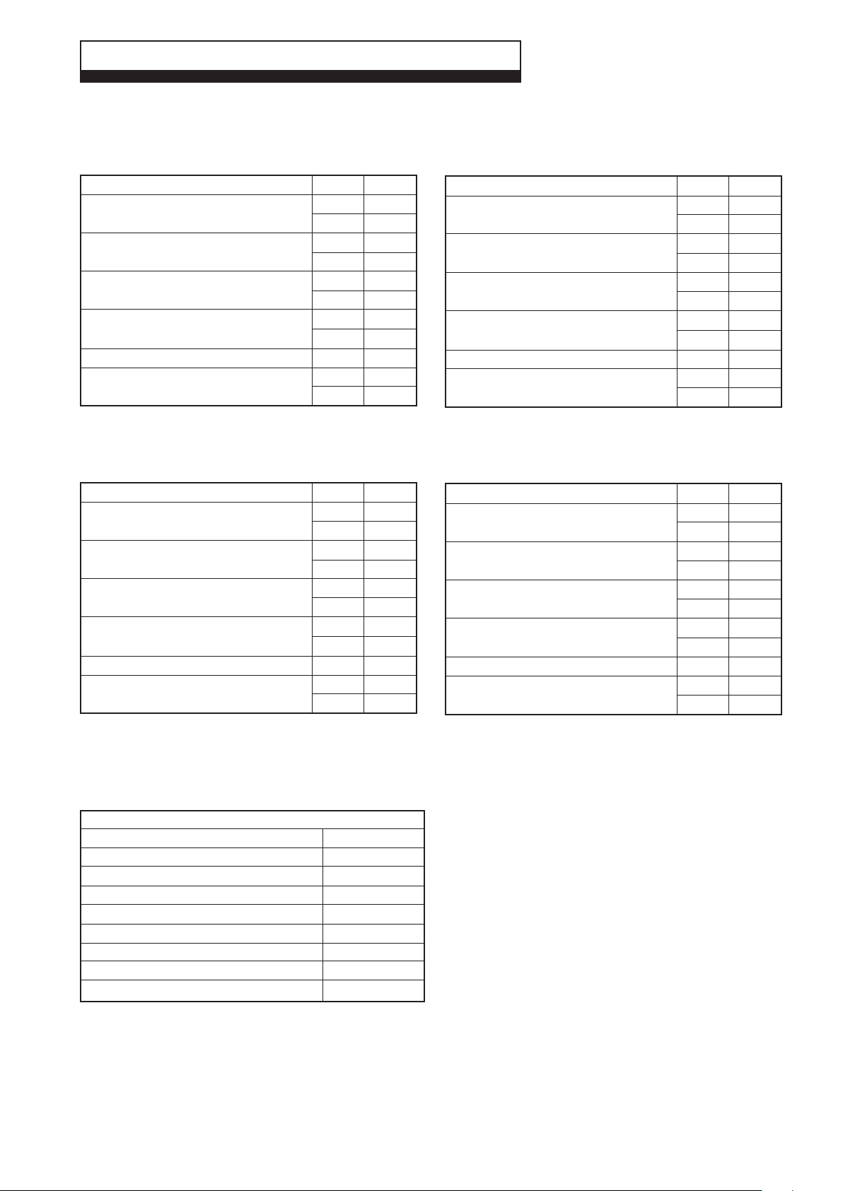
2 TECHNICAL DA T A
2.1 PERFORMANCE
NATURAL GAS (CAT: I2H 2H - G20 - 20 mbar)
Alpha CD50S
Central Heating
Heat Input (H
)kW
s
(Gross) Btu/h
Heat Input (Hi)kW
(Net) Btu/h
Heat Output (Hs condensing) kW
(50°C/30°C) Btu/h
Heat Output (Hi non-condensing) kW
(80°C/60°C) Btu/h
Fan Speed rpm
Gas Rate m³/h
ft³/h
MAX.
56.4
192 400
50.8
173 300
53.8
183 700
50.0
170 600
5 180
5.37
189.6
MIN.
11.5
39 250
10.4
35 500
11.1
37 800
10.0
34 120
1 280
1.10
38.8
PROPANE GAS (CAT I3P 3P - G31 - 37 mbar)
Alpha CD50S
Central Heating
Heat Input (H
)kW
s
(Gross) Btu/h
Heat Input (Hi)kW
(Net) Btu/h
Heat Output (Hs condensing) kW
(50°C/30°C) Btu/h
Heat Output (Hi non-condensing) kW
(80°C/60°C) Btu/h
Fan Speed rpm
Gas Rate m³/h
ft³/h
MAX.
56.4
192 400
50.8
173 300
53.8
183 700
50.0
170 600
5 200
2.15
75.9
MIN.
11.5
39 250
10.4
35 500
11.1
37 800
10.0
34 120
1 250
0.44
15.5
Alpha CD70S
Central Heating
Heat Input (H
)kW
s
(Gross) Btu/h
Heat Input (Hi)kW
(Net) Btu/h
Heat Output (Hs condensing) k W
(50°C/30°C) Btu/h
Heat Output (Hi non-condensing) kW
(80°C/60°C) Btu/h
Fan Speed rpm
Gas Rate m³/h
ft³/h
MAX.
77.5
264 300
69.8
238 200
72.8
248 600
67.9
231 700
5 240
7.4
261.2
70 060
63 120
67 100
61 800
Alpha CD70S
Central Heating
Heat Input (H
)kW
s
(Gross) Btu/h
Heat Input (Hi)kW
(Net) Btu/h
Heat Output (Hs condensing) k W
(50°C/30°C) Btu/h
Heat Output (Hi non-condensing) kW
(80°C/60°C) Btu/h
Fan Speed rpm
Gas Rate m³/h
ft³/h
MAX.
77.5
264 300
69.8
238 200
72.8
248 600
67.9
231 700
5 240
2.96
104.5
70 060
63 120
67 100
61 800
MIN.
20.5
18.5
19.7
18.1
1 400
1.96
69.2
MIN.
20.5
18.5
19.7
18.1
1 450
0.78
27.7
Note: The above appliances are fully modulating and are not range rated.
2.2 SYSTEM
Central Heating (Sealed System)
Max. Working System Pressure
Min. System Pressure
Max. System temperature
Pressure Relief Valve Setting
Flow Connection
Return Connection
Relief Valve Connection
Recommended System Pressure (cold)
CH Water Temp. (Approx. max.)
3.5 bar
0.5 bar
82°C
4 bar (58.8 PSI)
1½" BSP
1½" BSP
¾" BSP
1.0 bar
82°C (180°F)
Alpha CD50S/70S - Technical Data
3
Page 4
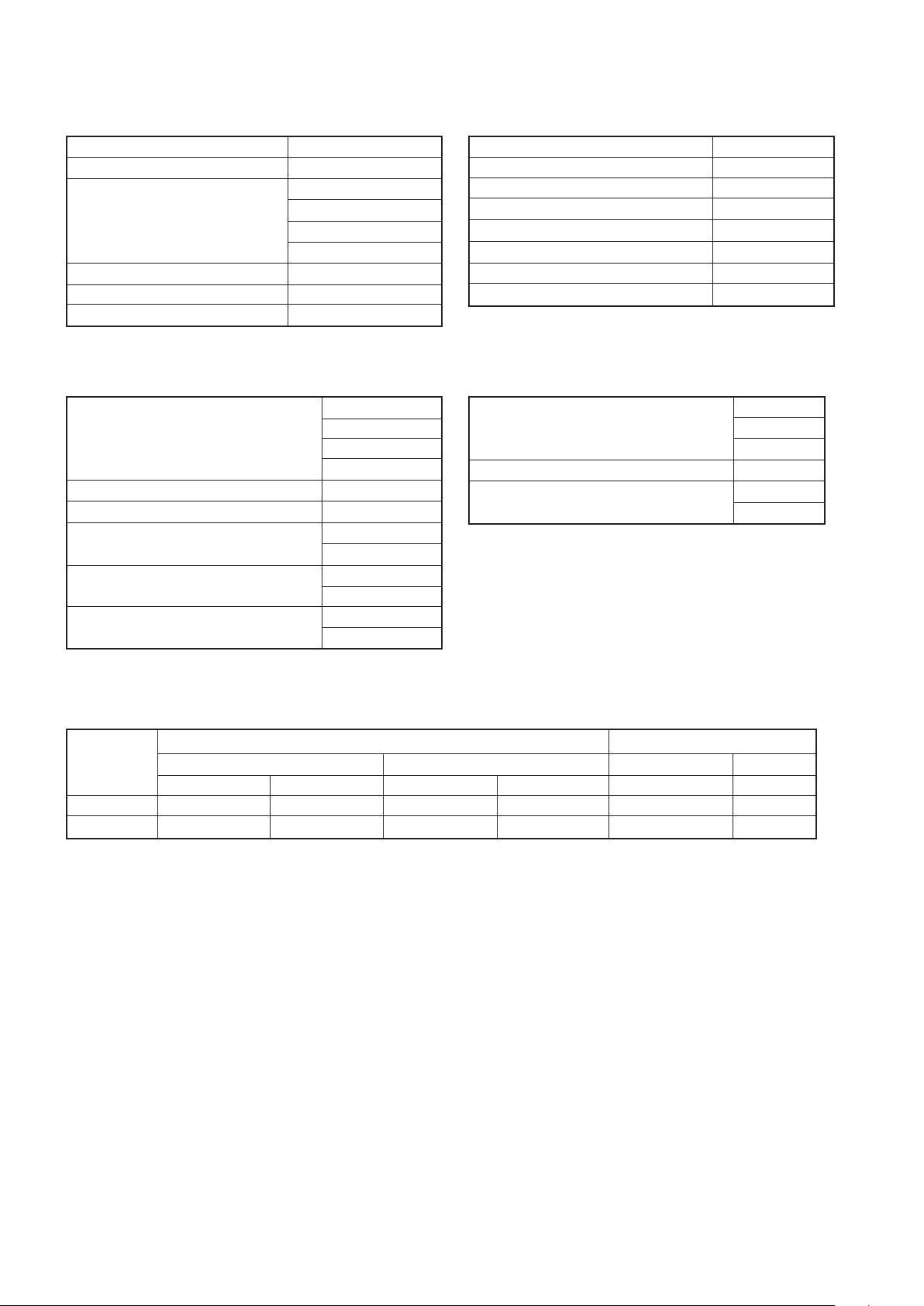
2.3 COMPONENTS 2.4 ELECTRICAL
Burner
Main Heat Exchanger
Main Burner Injector CD50S NG
CD70S NG
CD50S LPG
CD70S LPG
Concentric Flue Outer Duct
Concentric Flue Inner Duct
Open Flue Single Flue Pipe
2.5 INSTALLATION
Min. Clearances for Servicing Top
(from casing) Bottom
Sides
Front
Flue Diameter Open Flue
Concentric Flue
Flue Protruding Outside Open Flue
Concentric Flue
Hole For Flue Assy. Open Flue
Concentric Flue
Lift Weight CD50S
CD70S
Stainless steel
Stainless steel
7.85 mm
13.0 mm
5.7 mm
7.8 mm
125 mm dia.
80 mm dia.
80 mm dia.
350 mm
250 mm
10 mm
450 mm
80 mm
125 mm
80 mm
180 mm
100 mm dia.
127 mm dia.
63 kg
68 kg
Supply
External Fuse
Power Consumption
Internal Fuse - Main Terminal
PCB Fuse F1
PCB Fuse F3
Electrode Spark Gap
Electrical Enclosure Degree of Moisture Protection
2.6 GENERAL
Case Dimensions Height
Width
Depth
Gas Connection
Water Content CD50S
CD70S
230/240 V ~ 50 Hz
3 A
180 W
F2A
T2A
T4A
3 to 4 mm
IPX5D
950 mm
600 mm
525 mm
28 mm
3.7 L
4.0 L
2.7 PERFORMANCE DATA
Boiler model
CD50S
CD70S
Natural Gas Efficiency
Min
9.25
9.00
%CO2 content (± 0.2%) Sedbuk rating
(LPG) Propane Gas
CH Max
9.30
9.25
Min
10.1
9.7
CH Max
10.6
10.5
band
A
A
NOx class
5
5
Alpha CD50S/70S - Technical Data
4
Page 5
2.8 FLUE LENGTHS - See also Section 3.4
Open flue - Maximum horizontal or vertical flue with single 80 mm dia. open flue is 30 metre
90° bend is equivalent to 2.1 m of flue length
45° bend is equivalent to 1.3 m of flue length
Vertical terminal is equivalent to 3 m of flue length
Concentric flue - Maximum horizontal flue is 14 metre, maximum vertical flue is 18 metre
90° bend is equivalent to 1.9 m of flue length
45° bend is equivalent to 1.4 m of flue length
Vertical terminal is equivalent to 3.4 m of flue length
Notes: 1. Ensure all flues slope downwards towards the boiler by a minimum of 25 to 30 mm per metre of flue.
2. It is recommended that horizontal and vertical flue assemblies should be supported approximately every 1.5 m
with access provided to the joints.
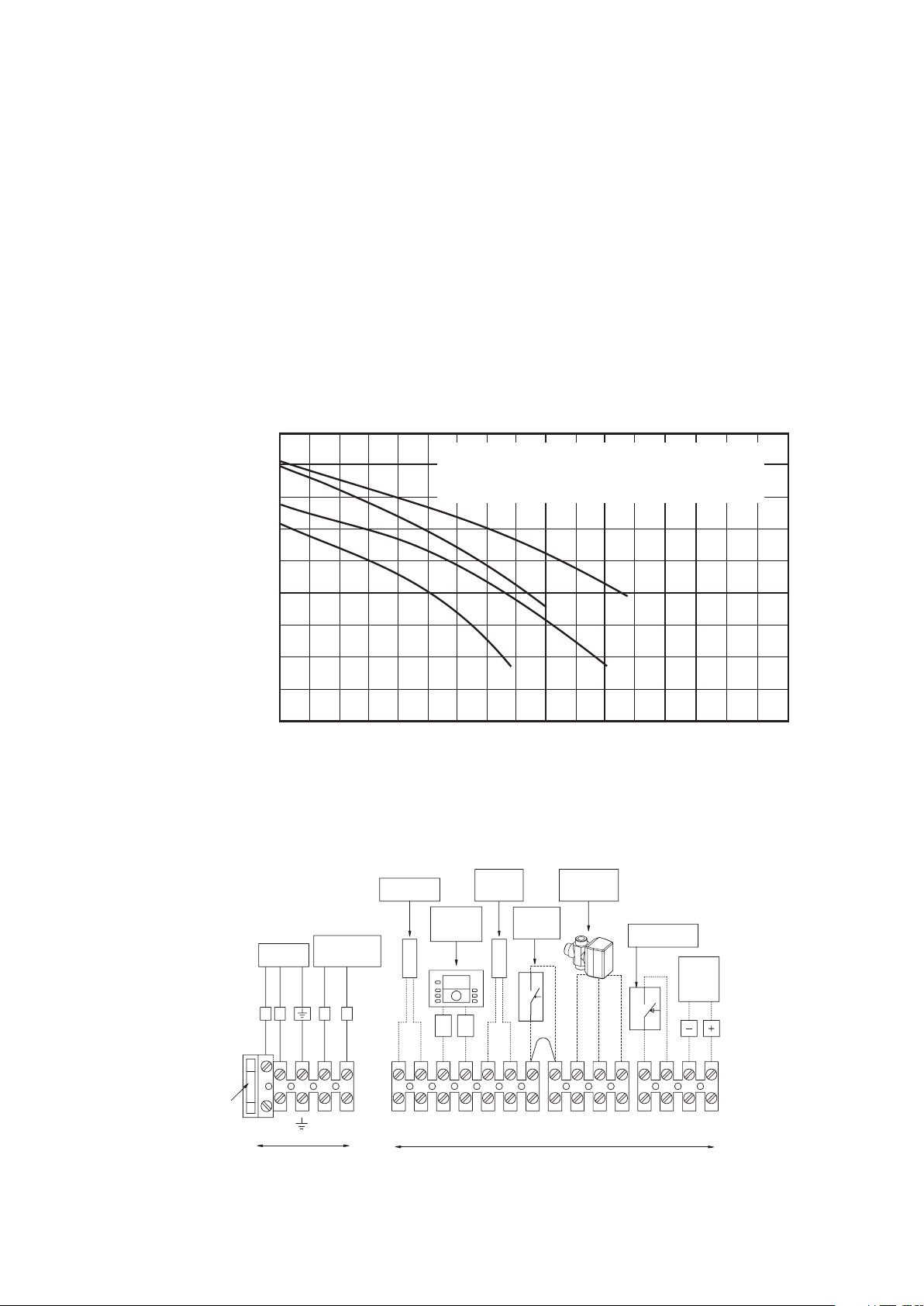
2.9 AVAILABLE PUMP HEAD FOR CENTRAL HEATING
9
A = CD50S - Available head with pump at maximum speed
B = CD50S - Available head with pump at speed two
C = CD70S - Available head with pump at maximum speed
D = CD70S - Available head with pump at speed two
D
C
TOTAL HEAD
(M water)
8
7
6
5
4
3
2
1
0
200 400 600 800 10001200 14001600 1800 20002200 2400 2600 2800 3000 32000
2.10 ELECTRICAL CONNECTIONS
Note: This Appliance Must Be Earthed
External Pump
Max 1A
(Optional)
N
N
Fuse F2A
230V ~ 50Hz
Fused at 3A
L
L
L
PQN
B
A
FLOW RATE (litre/h)
Fig. 1
External sensor
(Optional)
Zone
manager
(Optional)
37A38
temp sensor
(Optional)
B
DHW
thermostat
Room
(Optional)
LINK
Diverter valve
motor
(Optional)
3
6
Summer switch
2
(Optional)
X85
GJ MOR HF E TS KVUY Z
Analog
input
0 - 10 Volt
(Optional)
X86
230/240 V ~ 50 Hz only Maximum 24 V connection only
Note: Do not connect 230/240 V ~ 50 Hz
Fig. 2
Alpha CD50S/70S - Technical Data
5
Page 6
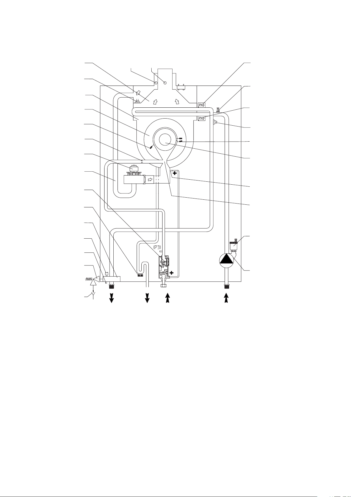
2.11 BOILER SCHEMATIC - CD50S
15
14
13
12
11
10
16 17
9
8
7
6
5
18
19
20
21
22
23
24
25
4
3
2
1
1 Tundish
2 Pressure relief valve (4 bar)
3 Drain point
4 Primary pressure switch
5 Flow manifold
6 Condensate trap
7 Gas valve
8 Air inlet pipe
9 Fan
10 Injector
11 Flame sensing electrode
12 Combustion chamber cover
13 Heat exchanger
14 Flue overheat thermostat
26
27
ReturnGasFlow Condensate
discharge
15 Flue hood
16 Air inlet sampling point
17 Flue sampling point
18 Primary flow temperature sensor
19 Air vent - manual
20 Primary return temperature sensor
21 Overheat thermostat
22 Ignition electrodes
23 Burner
24 Venturi positive point (P1)
25 Venturi
26 Automatic air vent
27 Pump
Alpha CD50S/70S - Technical Data
6
Fig. 3 - CD50S
Page 7
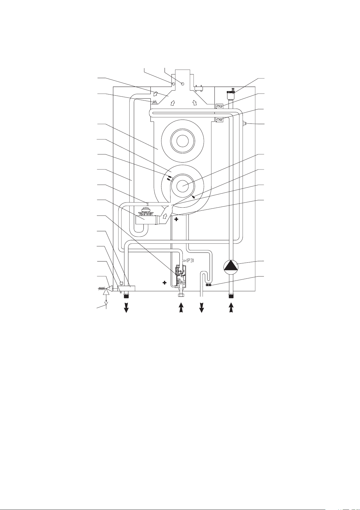
2.12 BOILER SCHEMATIC - CD70S
15 16
14
13
12
11
10
17
18
19
20
21
9
8
7
6
5
4
22
23
24
3
2
1
1 Tundish
2 Pressure relief valve (4 bar)
3 Drain point
4 Primary pressure switch
5 Flow manifold
6 Gas valve
7 Fan
8 Injector
9 Air inlet pipe
10 Ignition electrodes
11 Combustion chamber cover
12 Hear exchanger
13 Flue overheat thermostat
25
26
ReturnGasFlow Condensate
discharge
14 Flue hood
15 Air inlet sampling point
16 Flue sampling point
17 Automatic air vent
18 Primary flow temperature sensor
19 Primary return temperature sensor
20 Overheat thermostat
21 Burner
22 Flame sensing electrode
23 Venturi
24 Venturi positive point (P1)
25 Pump
26 Condensate trap
Fig. 4 - CD70S
Alpha CD50S/70S - Technical Data
7
Page 8
3 GENERAL BOILER INFORMATION
3.1 GAS SUPPLY
Natural Gas:
The Alpha CD50S boiler requires a gas rate of 5.37 m³/h (189.6 ft³/h).
The Alpha CD70S boiler requires a gas rate of 7.4 m³/h (261.2 ft³/h).
Propane Gas (LPG):
The Alpha CD50S boiler requires a gas rate of 3.94 kg/h (8.4 lb/h) or 7.6 litres/h of liquid gas.
The Alpha CD70S boiler requires a gas rate of 5.42 kg/h (11.6 lb/h) or 10.4 litres/h of liquid gas.
The local Propane Gas supplier should be consulted, at the installation planning stage, in order to establish the
availability of an adequate supply of gas.
The meter and supply pipes must be capable of delivering this quantity of gas in addition to the demand from any other
appliances. The boiler requires at least a 28 mm gas supply pipe and ensure the inlet supply pressure is at least 20 mbar
for Natural Gas or 37 mbar for Propane Gas (LPG).
The complete installation, including the meter, must be tested for gas tightness and purged as described in BS 6891.
3.2 ELECTRICAL SUPPLY
The boiler requires a 230/240 V ~ 50 Hz mains supply, fused at 3 A
Note: The boiler must be earthed.
There must only be one common isolator, providing complete electrical isolation, for the boiler and any external controls.
This boiler has been fitted with a supply cable, however, if it is necessary to fit a cable use PVC insulated cable not less
than 0.75 mm² (24 x 0.2 mm) to BS 6500 Table 16. The boiler should be connected to a fused three pin plug and
unswitched shuttered socket outlet (both complying with BS 1363), or a fused double pole switch with a contact
separation of at least 3 mm in both poles.
Wiring external to the boiler must be in accordance with the current IEE Wiring Regulations (BS 7671).
3.3 AIR SUPPLY
Open flued (Type B23 flue)
Alpha CD50S and CD70S boilers leave the factory with 'B23' type configuration (open chamber and forced draught single flue pipe) and receive the air for combustion from openings in the rear of the boiler, therefore air supply for
combustion and ventilation must be provided in accordance with BS5440:2.
1. If the boiler is installed in a room - The room must have a permanent air vent either direct to the outside air or to an
adjacent room which itself has a permanent air vent to the outside air. The minimum effective air vent(s) required is:
Alpha CD50S: 220 cm² Alpha CD70S 315 cm²
2. If the boiler is installed in a cupboard or compartment - Permanent air vents are required in the cupboard or
compartment, one at high level and one at low level, either direct to the outside air or to a room. Both the high and
low level air vents must communicate with the same room or must be on the same wall to outside air. The minimum
effective areas required are given in Table 1.
Where the cupboard or compartment is ventilated to a room, the room itself must have an effective air vent direct to
outside air of minimum effective area as given above in paragraph 1.
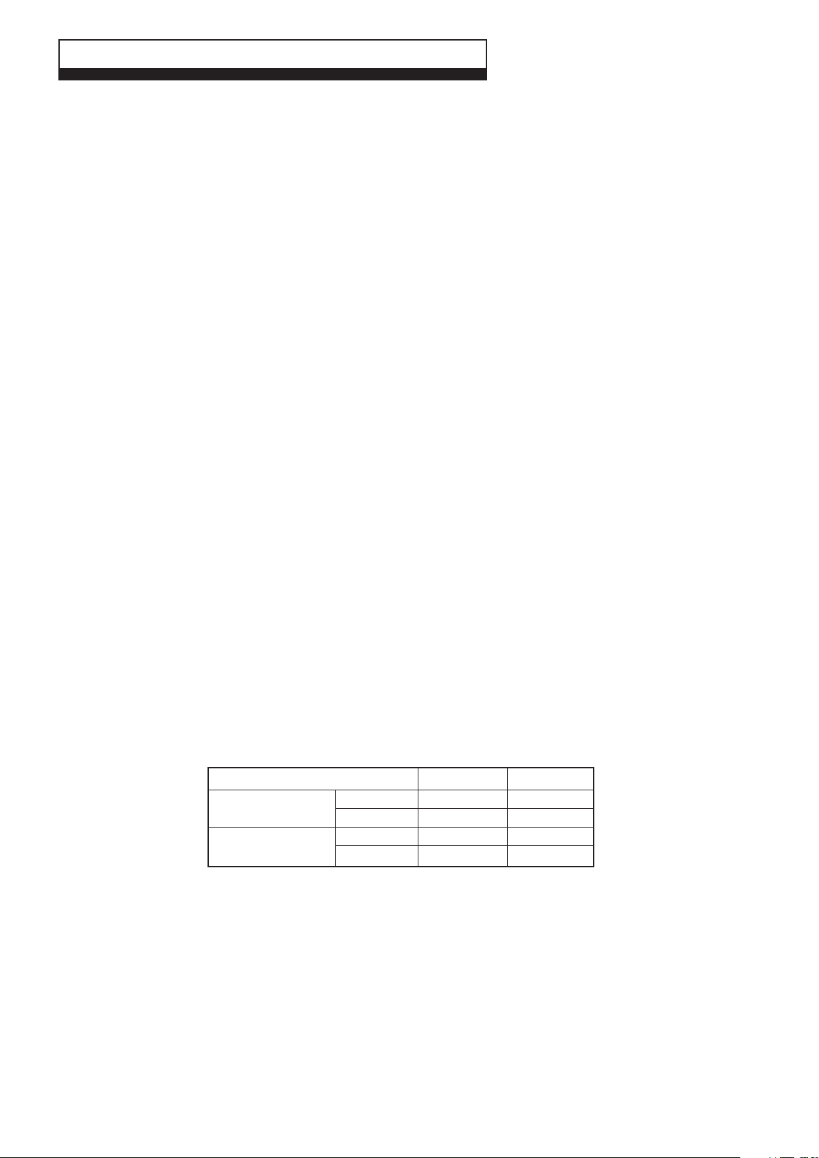
Boiler model
Vents to outside air
Vents into a room
High level
Low level
High level
Low level
CD50S
255 cm²
510 cm²
510 cm²
1020 cm²
CD70S
350 cm²
700 cm²
700 cm²
1400 cm²
Table 1
Room sealed (Type C flue)
If the boilers are converted to a 'C' type configuration (sealed chamber and forced draught - concentric flue pipe) as
described in Section 3.4 only air for ventilation is required.
1. If the boiler is installed in a room - No air vents are required in the room in which the boiler is installed.
2. If the boiler is installed in a cupboard or compartment - Permanent air vents for ventilation are required in the
cupboard or compartment, one at high level and one at low level, either direct to the outside air or to a room. Both
the high and low level air vents must communicate with the same room or must be on the same wall to outside air.
Both the high and low level vent must each have a free area as follows. The free area of each vent may be halved if
the ventilation is provided directly from outside.
Alpha CD50S: 510 cm² Alpha CD70S 700 cm²
The minimum clearances for servicing must always be maintained.
Alpha CD50S/70S - General Boiler Information
8
Page 9
3.4 FLUE SYSTEM
The flue system must be installed in accordance with BS 5440:1.
For horizontal flues ensure the flue assembly slopes downwards towards the boiler by a minimum of 25 - 30 mm per
metre of flue.
It is recommended that horizontal and vertical flue assemblies should be supported approximately every 1.5 m with access
provided to the joints.
Alpha CD50S and CD70S boilers leave the factory with 'B23' type flue configuration (open chamber and forced draught -
single flue pipe). To change the configuration to 'C' type (sealed chamber and forced draught - concentric flue pipe),
remove the 80 mm dia. adapter, the bracket and gasket from the top of the boiler and fit the concentric flue adaptor, see
Section 4.5.
Note: 1. Under no circumstances must the flue length (including allowances for extra bends) exceed the maximum flue
lengths stated for each type of flue.
2. Failure to use the correct Alpha flue components with the boiler will invalidate the boilers CE approval, guarantee
and may be unsafe.
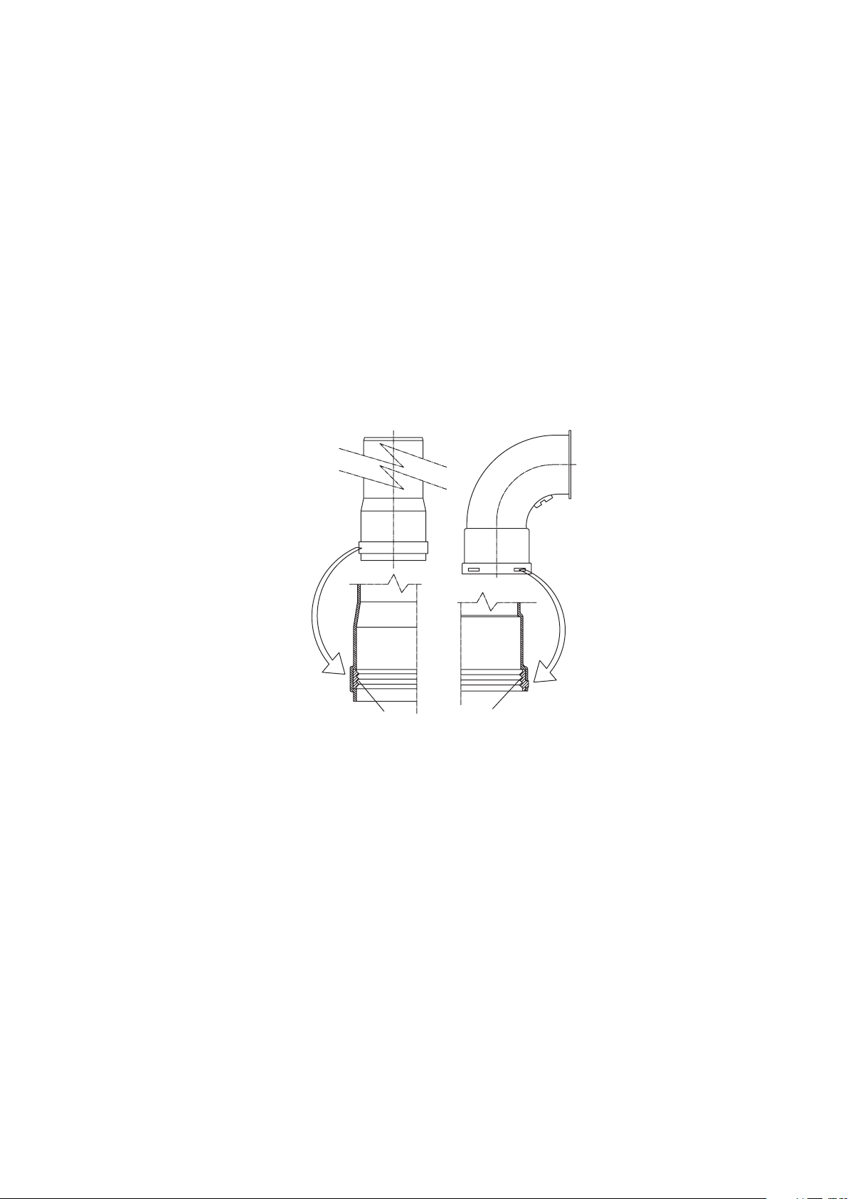
Seals for flue elements - If lubrication of components (already performed by the manufacturer) is not sufficient, remove
the residual lubricant using a dry cloth, then to ease fitting apply a small amount of common or industrial talc to the seal.
Ensure that the seals are correctly located in the elbows and extensions as shown in Fig. 5.
Seal Seal
Fig. 5
Flue components are available as follows:-
Open flue - 80 mm dia. single pipe
Horizontal terminal kit 80 mm dia. (includes 1 m straight with terminal, one 90° bend and two collars)
Vertical terminal kit 80 mm dia.
Extension pipe 1 m x 80 mm dia.
90° bend 80 mm dia.
45° bend 80 mm dia.
Concentric flue - 80/125 mm dia.
Horizontal terminal kit 80/125 mm dia. (includes 1 m straight with terminal, one 90° bend, two collars and adaptor)
Vertical terminal kit 80/125 mm dia. (includes adaptor)
Extension kit 1 m x 80/125 mm dia.
90° bend 80/125 mm dia.
45° bend 80/125 mm dia.
Alpha CD50S/70S - General Boiler Information
9
Page 10
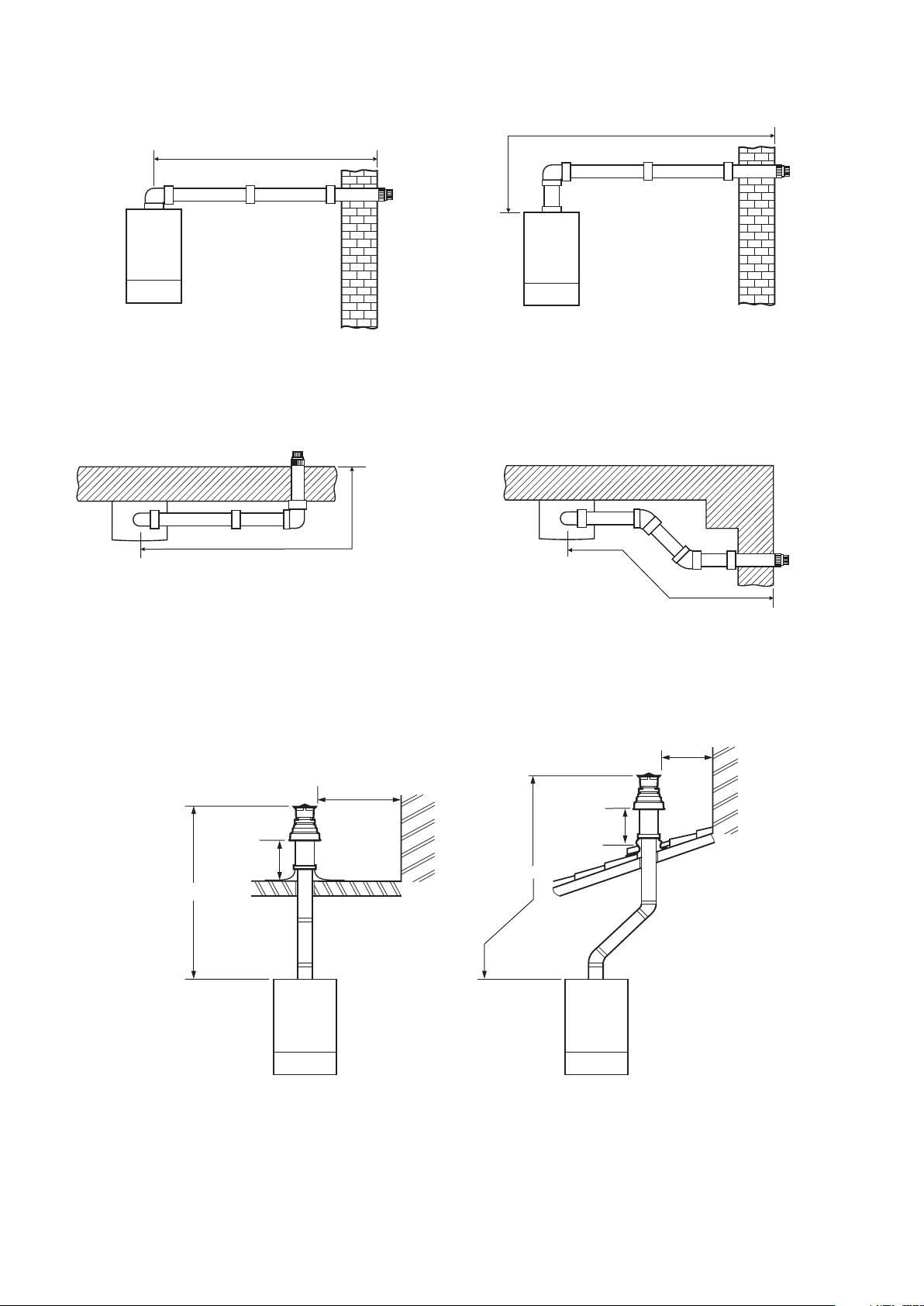
3.4.1 Horizontal Flue Options
L max
L max
L max
Open flue: 80 mm dia. single pipe Lmax = 30 m
90° bend is equivalent to 2.1 m of flue length
45° bend is equivalent to 1.3 m of flue length
Concentric flue: 80/125 mm dia. Lmax = 14 m
90° bend is equivalent to 1.9 m of flue length
45° bend is equivalent to 1.4 m of flue length
Open flue: 80 mm dia. single pipe Lmax = 27.9 m
Concentric flue: 80/125 mm dia. Lmax = 12.1 m
3.4.2 Vertical Flue Options
Not less than
300 mm
Not less than
300 mm
H
L max
Open flue: 80 mm dia. single pipe Lmax = 27.4 m
Concentric flue: 80/125 mm dia. Lmax = 11.2 m
Fig. 6 - Horizontal flues
Not less than
300 mm
Not less than
300 mm
H
Open flue: 80 mm dia. single pipe Hmax = 30 m
Concentric flue: 80/125 mm dia. Hmax = 18 m
Alpha CD50S/70S - General Boiler Information
10
Open flue: 80 mm dia. single pipe Hmax = 27.4 m
Concentric flue: 80/125 mm dia. Hmax = 15.2 m
Fig. 7 - Vertical flues
Page 11
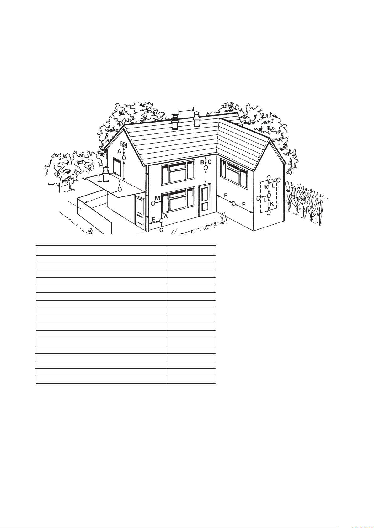
3.5 FLUE TERMINAL LOCATION - Fig. 8
Note: In certain weather conditions the terminal will emit a plume of steam. If possible avoid positioning the terminal where this may
cause a nuisance, i.e. positions A, D, G, H, J or M.
The flue terminal must be exposed to the external air and the position must allow the free passage of air across it at all times.
A terminal must not be sited below 2.1 m where people have access to, such as public footpaths, access routes, patios
etc. However, If the terminal is fitted less than 2.1 m above a surface where there is no public access, the terminal must
be protected by a terminal guard. A suitable guard is available from Alpha Therm Ltd.
Q
P
O
G
N
D
J
Boundary
A Directly below an opening, air brick, windows, etc.
B Below gutters, soil pipes or drain pipes
C Below eaves
D Below balconies
E From a vertical drain pipe or soil pipe
F From an internal or external corner
G Above ground, roof or balcony level
H From a surface or boundary facing the terminal
I From a terminal facing the terminal
J Above an opening, air brick, window etc.
K Vertically from a terminal on the same wall
L Horizontally from a terminal on the same wall
M Horizontally from an opening, air brick, window etc.
N Minimum protrusion through a roof
O From a vertical obstruction
P From an openable window
Q From an adjacent vertical terminal
HI
Min. distance (mm)Terminal position
300 mm (See Note 1)
Note: A terminal must not be sited under a car port roof
300 (See Note 1)
75 (See Note 3)
200 (See Note 3)
200 (See Note 3)
150 (See Note 3)
300 (See Note 2)
300
600 (See Note 4)
1200 mm
300 (See Note 1)
1500 mm
300 mm
300 mm
300 mm
600 mm
600 mm
Fig. 8
Notes: 1.In addition, the terminal should not be nearer
than 150 mm to the framework of an
opening into the buiding, i.e. a window
surround or door surround.
2.This clearance may be reduced to 25 mm
without effecting the performance of the
boiler. However, to ensure the condensate
plume does not affect adjacent surfaces a
clearance of 300 mm is preferable.
3.These clearances may be reduced to 25 mm
without effecting the performance of the boiler.
However, to ensure the condensate plume
does not affect adjacent surfaces the terminal
can be extended beyond gutters, pipes, eaves,
balconies etc. by upto 500 mm. If the flue is
extended more than 500 mm outside, it should
be boxed and insulated.
4.To reduce the possibility of nuisance to
neighbouring buildings etc. it is
recommended the terminal shouild not be
less than 2500 mm from car parking spaces,
building boundary walls, fences etc.
3.6 BOILER LOCATION
The boiler is not suitable for external installation unless it is installed within a purpose designed weatherproof building.
The boiler must be installed on a flat vertical wall which is capable of supporting the weight of the boiler. The boiler can be
fitted to or adjacent to a wall comprising of a combustible material without the need for a special thermal insulation barrier.
If the boiler is to be fitted in a timber framed building, it should be fitted in accordance with the Institute of Gas Engineers
'Guide for Gas Installations in Timber Frame Housing', reference IGE/UP/7.
The boiler may be installed in any room or internal space, although particular attention is drawn to the requirements of the
current IEE Wiring (BS7671) Regulations, and in Scotland, the electrical provisions of the Building Regulations applicable in
Scotland, with respect to the installation of the boiler in a room or internal space containing a bath or shower. Where a roomsealed boiler is installed in a room containing a bath or shower, it must not be possible for a person using the bath or shower
to touch any electrical switch or boiler control utilising mains electricity.
The boiler may be installed in a cupboard or compartment, provided it is correctly designed for that purpose, i.e. complies
with the Building Regulations and the requirements of BS 6798.
Alpha CD50S/70S - General Boiler Information
11
Page 12
Propane Gas (LPG): Installation pipes, cylinders and pressure regulators should be fitted in accordance with BS 5482:1.
Bulk tank installation must comply with the requirements of the Home Office code of practice for the storage of liquefied
petroleum gas at fixed installations. The boiler must not be installed in a room or internal space below ground level, e.g.
in a basement or cellar, except where at least one side is open to ground level.
3.7 FROST PROTECTION
The boiler is fitted with a frost thermostat that activates the pump and burner when the system water temperature in the
boiler falls below 3°C.
The electrical supply to the boiler must be left on for the thermostat to operate and the selector switch must be set to ON .
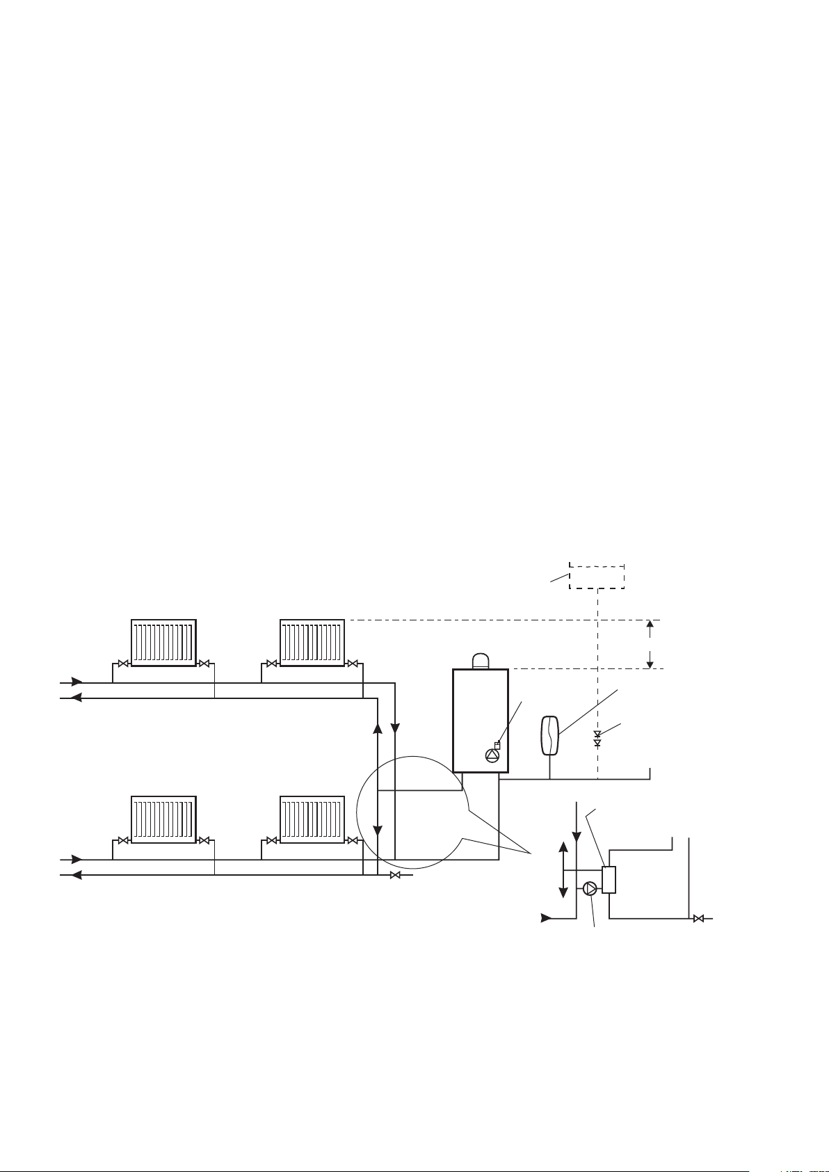
3.8 CENTRAL HEATING SYSTEM - Fig. 9
The boiler is designed for use in a sealed central heating system in accordance with the requirements of BS 5449 and BS 6798.
The system should be designed to operate with flow temperatures of up to 82°C. When designing the system, the pump head,
expansion vessel size, mean radiator temperature, etc. must all be taken into account. Refer to the pump performance graph
for guidelines (see Fig. 1).
However, if the boiler is to be used with an open central heating system refer to Fig. 9 and use a barrier heat exchanger (i.e.
separates the boiler primary circuit from the open heating circuit). This will also ensure the boiler heat exchanger is protected
from an old/dirty system.
Sealed system volume - An expansion vessel is not incorporated into the boiler. An expansion vessel must be fitted in
the position shown in Fig. 9. To check correct operation of the expansion vessel the system pressure should not be more
than 3.5 bar when the system is at maximum operating temperature (for further guidance refer to BS 7074:1), For
example an 8 litre expansion vessel is suitable for a sealed system of 80 litres.
The boiler is supplied with the following components built in:Pressure relief valve - complying with BS 6759 and set to operate at 4 bar. The discharge pipe must be routed clear of
the boiler and terminated in such a manner that it can be seen, but cannot cause injury to persons or property.
Pressure gauge - To indicate the system pressure to be maintained.
By-pass - The boiler has no built-in by-pass, therefore an automatic by-pass is required for the system.
Note: A drain tap should be installed at the lowest
point of the heating circuit and beneath the appliance.
Heating flow
System
drain tap
Fig. 9
Make up vessel
(sealed system only)
Boiler
Heating return
Return
Automatic
air vent
Return
Flow
Flow
Fit pump if Barrier
heat exchanger used
Static head of system
Expansion vessel
(sealed system only)
Double check valve assy.
(sealed system only)
Filling point
(sealed system only)
Barrier heat exchanger used on
open or old/dirty systems
Heating flow
Heating return
Drain
tap
Installation on a low temperature heating system.
The boiler can directly feed a low temperature system, varying the maximum delivery temperature of the boiler and
setting a value of between 20 and 85°C. To vary the boiler maximum delivery temperature, modify the boiler maximum
delivery temperature of parameter No. 4 as described in Section 5.8 and Table 6.
In this mode it is advisable to include a safety limit thermostat set at 55°C in series with the boiler circulating pump. The
thermostat must be positioned in the system flow pipe at more than 2 metres from the boiler.
Alpha CD50S/70S - General Boiler Information
12
Page 13
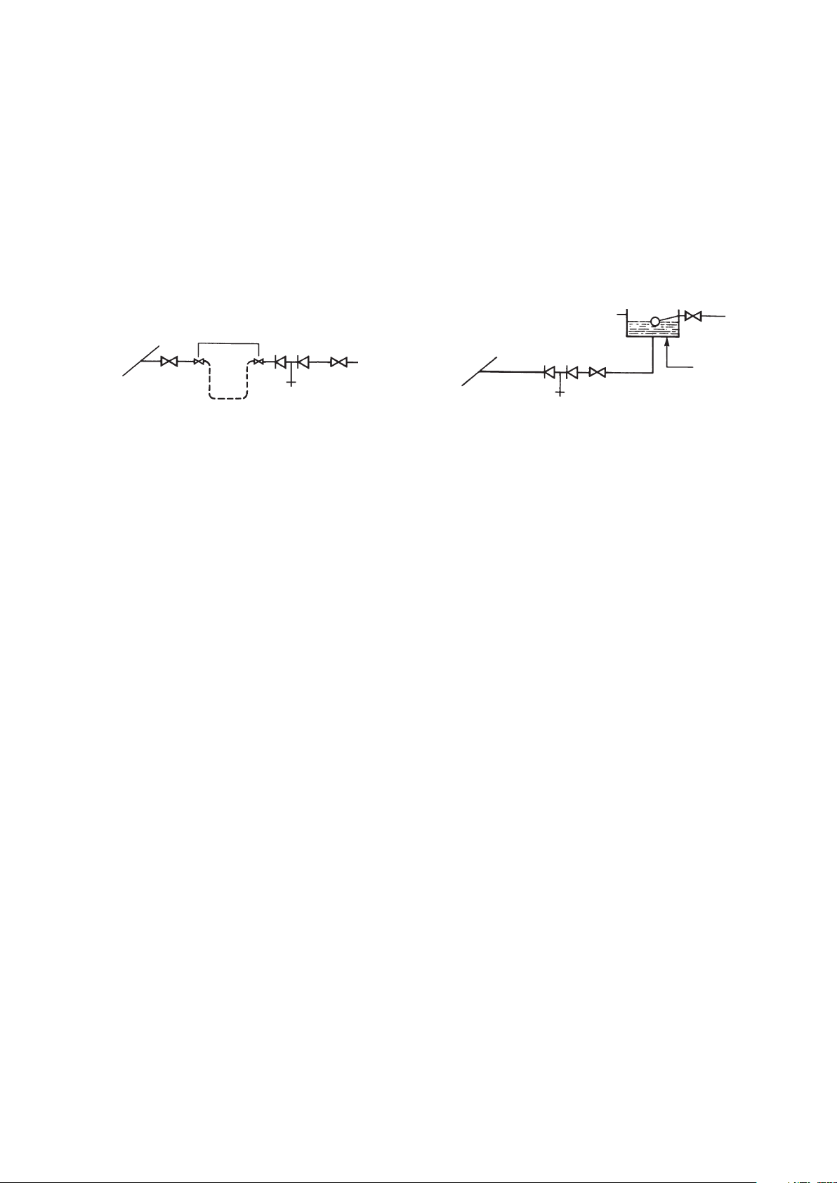
3.9 FILLING THE SEALED CENTRAL HEATING SYSTEM - Figs. 10, 11
The system design pressure (cold) should be set to 1.0 bar. This pressure is equivalent to a static head (see Fig. 9) of
10.2 metres of water.
Provision should be made to replace water lost from the system. This can be by manual or automatic means, as shown in
Figs. 10 and 11. The position for connecting an automatic make-up vessel is indicated in Fig. 9. A double check valve
assembly must be used, as shown in Fig. 11.
Filling of the system must be carried out in a manner approved by the local Water Undertaking. Where allowed, the
system may be filled via a temporary connection as shown in Fig. 10. After filling, always disconnect the flexible hose of
the filling loop.
All fittings used in the system must be able to withstand pressures up to 4 bar.
Drain taps (to BS 2879) must be used to allow the system to be completely drained.
Mains
water
supply
Feed cistern to be
located above highest
point in the system
Heating circuit
return
Stop
valve
temporarily connected
Hose
unions
Filling loop
Double check
valve assembly
Test cock
Stop
valve
Mains
water
supply
Heating circuit
return
Double check
valve assembly
Test cock
Overflow
Stop
valve
Fig. 10 Fig. 11
3.10 FLUSHING THE HEATING SYSTEM
It is essential that the central heating system is thoroughly cleaned and flushed when fitting an Alpha CD50S or CD70S
boiler. Failure to do so will invalidate the warranty. If this is difficult because the system is old/dirty refer to Section 3.8,
Fig. 9 gives consideration to using a barrier heat exchanger.
The primary condensing heat exchanger is constructed in stainless steel and therefore is compatible with most materials
used in a heating system.
If a cleaning agent and inhibitor are used, they must be applied in accordance with their manufacturers instructions. Only
products from Fernox and Sentinel are acceptable for use with the Alpha CD50S or CD70S boilers. Further information
can be obtained from Fernox (Tel: 0179 9521133) or Sentinel (Tel: 0151 4209563).
The system should be flushed in accordance with BS 7593 and BS 5449. The following procedures are recommended:
1. Installing onto a new system:a.Fill the system, vent at high points, at pump and radiators.
b. Check for leaks.
c.Rapidly drain the system.
d. If required, chemically clean the system as instructed by the recommended cleaner manufacturer.
Note: Ensure that the system is flushed to remove any remains of the cleaner.
e. If chemical cleaner is not used to clean the system:-
i) Refill the system.
ii) Switch on the boiler and allow the system to heat up to the normal operating temperature.
iii) Rapidly drain the system while the water is still hot.
iv) Refill the system.
f. As required, add the recommended inhibitor to the system as instructed by the inhibitor manufacturer.
g. Recheck for leaks.
2. Installing onto an existing system, clean the system before fitting the new boiler:a.If the old boiler is still working:-
i) Switch on the boiler and allow the system to heat up to the normal operating temperature.
ii) Rapidly drain the system while the water is still hot.
iii) Refill and chemically clean the system as instructed by the recommended cleaner manufacturer.
iv) Ensure the system is flushed to remove any remains of the cleaner.
v) Fit the new boiler.
b.If the old boiler is not working:-
i) Rapidly drain the system.
ii) Remove the old boiler.
iii) Flush the system through.
iv) Fit the new boiler.
v) Refill and chemically clean the system as instructed by the recommended cleaner manufacturer.
vi) Ensure the system is flushed to remove any remains of the cleaner.
c.As required, add the recommended inhibitor to the system as instructed by the inhibitor manufacturer.
d. Check for leaks.
Alpha CD50S/70S - General Boiler Information
13
Page 14
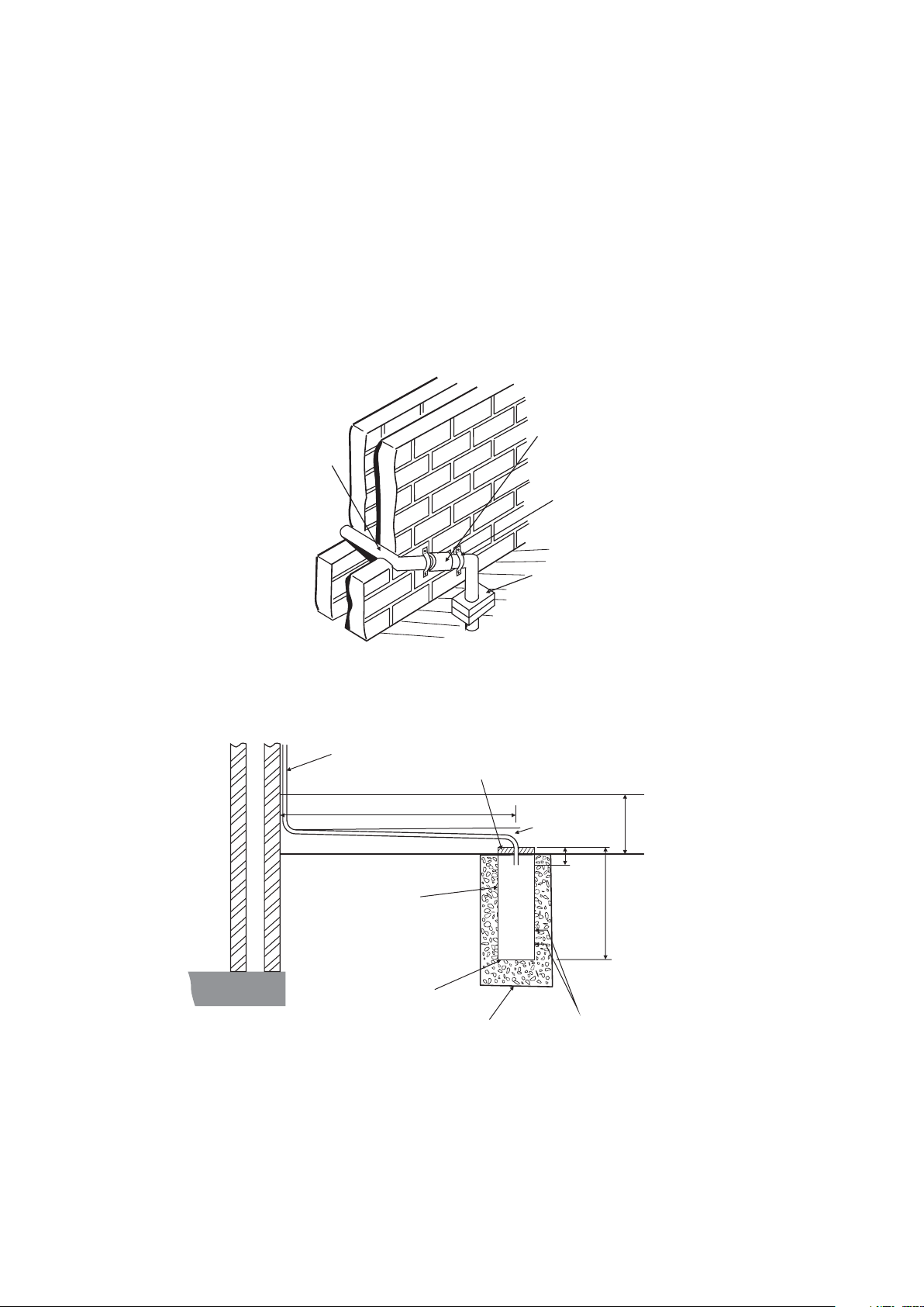
3.11 DISPOSAL OF CONDENSATE
Provision must be made for the safe disposal of condensate produced by the flue gases of the Alpha CD50S or CD70S
boilers and reference should be made to BS 6798: 2000 for the requirements on the disposal of condensate.
The boilers incorporate a condensate trap which has a seal of 75 mm, therefore no additional trap is required.
The condensate should ideally be discharged internally into an internal waste pipe (washing machine/sink waste) or soil
pipe to avoid the possible risk of freezing. The pipework must be in 22 mm pipe.
External pipe runs should be avoided, but if it is necessary, the pipework should be at least 32 mm and protected from
the risk of freezing with a waterproof insulation and the length should be kept to a maximum of 3 m. Termination should
be into an external gulley or soakaway as shown in Figs. 12 and 13.
Note: All pipework must have a continuous fall (see Figs. 12 and 13) from the boiler and must be of an acid resistant
material such as plastic waste pipe. (copper or steel is not suitable).
It should be noted that the connection of a condensate pipe to a drain may be subject to local building control requirements.
Use waterproof
pipework insulation
Plastic pipe
in very exposed
positions
Ensure pipe is
adequately supported
Minimum gradient 2½°
Fig. 12 - External gully
22mm termination
from boiler
500 mm min.
100mm plastic tube
Bottom of tube sealed
Soakaway depth 400mm
filled with limestone chippings
Cement mortar
sealing
Open end of pipe
diverted into gully
below grid but above
water level
O
2½ fall
25mm
Ground level (either/or)
300mm
Two rows of 3 x 12mm
holes at 25mm centres,
50mm from the bottom
of the tube. Holes to face
away from house.
Alpha CD50S/70S - General Boiler Information
14
Fig. 13 - External soakaway
Page 15
4 INST ALLATION
4.1 UNPACKING
1. The basic boiler is supplied in a single box, containing the following:Cased boiler supplied with water connections and washers
Mounting hooks and wall plugs
Tundish for pressure relief valve outlet
Condensate discharge pipe
Gas service cock and 28 mm connection tail
Literature pack and Wall template
Other parts of the flue system are supplied in seperate packs as ordered.
2. Unpack boiler and remove the loose items.
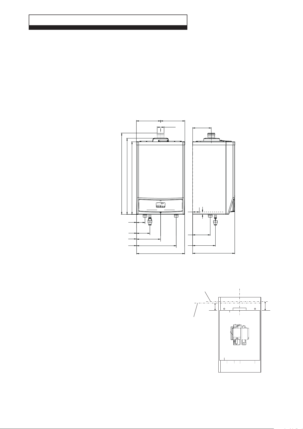
4.2 DIMENSIONS and CONNECTIONS- Fig. 14
1010
Heating flow B
Pressure relief valve discharge C
Gas A
Heating return B
950
905
105
300
170
300
Alpha CD70S
495
600
Fig. 14
300
23280 Dia.
70
A
B
C
25
220
285
525
4.3 PREPARE THE WALL - Fig. 15
1. Decide upon the position of the boiler taking into account the clearances
required for servicing (refer to Section 2.5) and the flue terminal position.
2. Tape the template to the wall (ensure it is level and the right way up)
and mark the position of the two holes for the boiler mounting hooks.
3. Drill the fixing holes (12 mm dia.) to accept the No.12 plugs supplied.
Screw the boiler mounting hooks fully into the plugs.
4. Cut suitable holes in the wall/roof 100 mm dia for open flue 80 mm dia.
pipe or 127 mm dia. for concentric flue. Use the centre line positions
given on the flue template.
5. Lift the boiler and locate it on the mounting hooks.
Note: When handling or lifting always use safe techniques - keep your
back straight, bend your knees, don't twist - move your feet, avoid bending
forwards and sideways and keep the load as close to your body as
possible.
Where possible transport the boiler using a sack truck or other suitable
trolley.
Always grip the boiler firmly, and before lifting feel where the weight is
concentrated to establish the centre of gravity, repositioning yourself as
necessary.
Centre line
for horizontal
concentric flue
170 mm
Centre line
for horizontal
open flue
Centre line for
vertical flues
MINIMUMTOP CLEARANCE 350 mm
BOILERMOUNTING
HOOKFIXING HOLE
TOPOF CASING
WITHCOVER
MINIMUMSIDE
CLEARANCE10 mm
BOTTOMOF CASING
HEATING
SAFETY
FLOW
VALVE
(11/2"BSP)
(3/4"BSP)
MINIMUMBOTTOM CLEARANCE 250 mm
WITHOUTHYDRAULIC OPTIONAL KIT
FORUSE WITH ALPHA CD50 - 70S
Alpha
GAS
(28mm)
Fig. 15
Alpha CD50S/70S - Installation
BOILERMOUNTING
HOOKFIXING HOLE
MINIMUMSIDE
CLEARANCE10 mm
HEATING
RETURN
(11/2"BSP)
200 mm
15
Page 16
4.4 CONNECT THE PIPEWORK - Fig. 14
1. Thoroughly flush out all the water pipework. Refer to Section 3.10.
2. Connect the system flow and return pipework to the boiler using suitable
isolating valves.
Note: Do not forget that the pressure relief valve discharge pipe must be
routed clear of the boiler to a drain in such a manner that it may be seen, but
cannot cause injury to persons or property.
3. Connect the 22 mm condensate trap drain pipe to the condensate discharge
pipe using the clip supplied.
Ensure that the condensate discharge pipe is as required in Section 3.11.
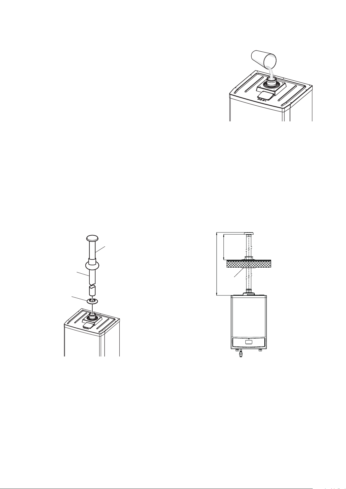
Pour at least 0.5 litre of water into the flue duct, as shown in Fig. 16, and
check the condensate discharge pipe for soundness
4. Ensure that all the valves are closed and do not turn on the water or gas supplies at
this stage.
Fig. 16
4.5 'B23' TYPE SINGLE PIPE 80 mm FLUE KITS
Vertical kit - see Fig. 17 and 18, and refer to Section 3.4.
Fig. 17 shows the vertical flue kit parts.
To assemble the kit to the boiler - Slide the flue pipe down through the roof seal and place the seal over the flue duct. Push
the flue duct into the flue socket on top of the boiler up to the stop. Ensure the seal is pushed in position against the ceiling.
The maximum vertical length (without bends) for flue pipe is 30 metres (see Fig. 17 and 18)
To install extensions or other flue components, proceed as follows: fit the male end of the pipe or elbow up to the stop on
the female socket (with lip seals) of the previously installed component, this will ensure a secure fit and seal of the joints.
Ensure all joints have the seal located correctly and the tape supplied is applied around each joint to ensure the flue
ducts cannot be pulled apart.
It is recommended that the flue should be supported approximately every 1.5 m with access provided to the joints.
430 mm
minimum
Seal
Flue pipe
Seal
Vertical terminal
Maximum
length 30 m
Fig. 17 Fig. 18
Horizontal through the wall kit - see Fig. 19 and 20, and refer to Section 3.4.
Fig. 19 shows the horizontal through the wall kit parts.
To assemble the kit to the boiler - Fit the male end of the flue elbow into central flue outlet on the top of the boiler to the
stop. Place the outer seal over the flue duct and slide it throught the wall from the outside. Place the inner seal over the
flue duct then insert the duct into the elbow up to the stop. Slide the seals along the duct to seal it to the inside and
outside of the wall.
To install extensions or other flue components, proceed as follows: fit the male end (smooth) of the pipe or elbow up to
the stop on the female socket (with lip seals) of the previously installed component, this will ensure a secure fit and seal
of the joints.
Extensions for flue kit - The maximum vertical/horizontal straight length (without flue bend) is 30 metres (refer to Section 3.4).
Note: To prevent condensate lying in the flue pipe, slope the pipe towards the boilers with a minimum slope of 2.5° - 3°
(25 - 30 mm per metre). When installing the extensions, a wall/ceiling mounted clamp must be installed every 1.5 metres.
Alpha CD50S/70S - Installation
16
Page 17
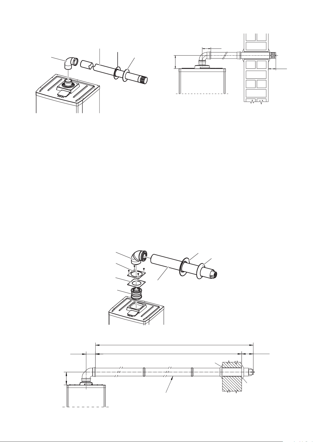
Flue elbow
Flue pipe
Fig. 19
Inner seal
Outer seal
170 mm
Note: Ensure the flue slopes downwards towards
the boiler by a minimum of 25 to 30 mm per metre (2.5° - 3°)
100 mm
80 mm
Fig. 20
4.6 'C' TYPE CONCENTRIC FLUE KITS
Convert the boiler from the factory supplied 'B23' type configuration to 'C' type, i.e. room sealed concentric flue by
removing the 80 mm dia. adaptor and four screws securing the fixing plate and gasket from the top of the boiler.
Horizontal through the wall concentric flue kit - see Fig. 21 and 22.
Fig. 21 shows the flue kit parts that need to be fitted to the boiler to ensure the room sealed concentric flue can be used.
To assemble the kit to the boiler - Fit the adapter into the central flue outlet on the top of the boiler up to the stop. Slide
the square gasket over the adapter up to the groove, then fix it to the cover by means of the previously removed fixing
plate and four screws. Fit the male end of the flue elbow up to the stop on the adapter. Place the outer seal over the
concentric flue pipe and slide it throught the wall from the outside. Place the inner seal over the concentric flue pipe then
insert the pipe into the elbow up to the stop. Slide the seals along the duct to seal it to the inside and outside of the wall.
To install extensions or other flue components, proceed as follows: fit the male end (smooth) of the concentric pipe or
concentric elbow up to the stop on the female socket (with lip seals) of the previously installed component, this will ensure
a secure fit and seal of the joints.
Extensions for horizontal kit - The horizontal kit can be extended up to a maximum horizontal distance of 14 metres
(Fig. 22), including the flue terminal and excluding the flue bend on the boiler (refer to Section 3.4).
Note: To prevent condensate lying in the flue pipe, slope the pipe towards the boilers with a minimum slope of 3° (25 - 30
mm per metre). When installing the extensions, a wall/ceiling mounted clamp must be installed every 1.5 metres.
200 mm
136 mm
Flue elbow
Fixing plate
Square gasket
Adapter
Inner seal
Outer seal
Concentric flue pipe
Fig. 21
Maximum 14000 mm
13820 mm
Inner seal
Note: Ensure the flue slopes downwards towards
the boiler by a minimum of 25 to 30 mm per metre (2.5° - 3°)
180 mm
Outer seal
Fig. 22
Alpha CD50S/70S - Installation
17
Page 18

4.7 CONNECT THE MAINS SUPPLY - Fig. 2
1. Remove the four screws securing the plastic top cover so that it can be lifted slightly at the front edge.
2. Remove the two fixing screws (one each side at the bottom) securing the case front panel (refer to Fig. 25). Pull the bottom
of the panel outwards while pushing up at the same time and remove the panel then remove the two screws securing the
control panel and lower the panel to gain access to the terminal block. Refer to Technical Data, Section 2.10 for
connection details.
3. Note: This boiler has been fitted with a mains supply cable. However, if it is necessary to fit an alternative supply cable,
ensure the cable clamp that has been fitted is removed and connect as follows:Pass the mains supply cable through the cable clamp and connect as follows:- Brown to L, Blue to N and Green/Yellow
to . Ensure correct polarity.
Note: Ensure that the length of the earth wire is such that if the supply cable is pulled out of its clamp the live and
neutral wires become taut before the earth wire.
Do not switch on the electrical supply at this stage.
4. If any external control, i.e. room thermostat etc. is to be fitted, refer to Fig. 2.
Note: All external control connections are less than 24 volts.
Do not connect 230/240 volts to any of the terminals G to Z on the X86 terminal block or to the X84 terminal block.
5. Ensure that there is sufficient free cable to allow the control panel to be raised and lowered then tighten the cable clamp
screws.
6. Leave the control panel open until commissioning procedures have been completed.
7. Carry out electrical system checks - Short circuit, Polarity, Earth continuity and Resistance to earth with a suitable
multimeter.
Alpha CD50S/70S - Installation
18
Page 19
5 COMMISSIONING
When commissioning the boiler, ensure the Benchmark Checklist is completed.
5.1 FILL THE SYSTEM
1. The boiler is fitted with an automatic air vent positioned as shown in Fig. 3, ensure that the vent is always open. The
CD50S also has a manual air vent (see Fig. 3)
2. Open the central heating flow and return valves.
3. Open the fill point valve on the filling loop until water is heard to flow.
4. To remove the air - Vent each radiator in turn, starting with the lowest in the system.
5. It is important that the pump is properly vented to avoid it running dry and damaging its bearings. Unscrew and
remove the cap from the centre of the pump. Using a suitable screwdriver rotate the exposed spindle about half a
turn, then replace the cap.
6. Check the operation of the pressure relief valve (see Fig. 3 or 4) by turning the head anti-clockwise until it clicks. The
click is the valve lifting off its seat allowing water to escape from the system - check that this is actually happening.
7. Continue to fill the system until the pressure gauge indicates 1.0 bar. Close the fill point valve and check the system for
water soundness, rectifying where necessary. Disconnect the filling loop from the mains supply. If the system has been
over pressurised water may be released from the system by manually operating the drain point (see Fig. 3 or 4) until the
system design pressure is obtained. The system design pressure (cold) should be between 0.75 and 1.25 bar.
Refer to Sections 3.9 and 3.10. Filling and Flushing the system.
5.2 TEST FOR GAS TIGHTNESS AND PURGE THE SUPPLY
1. With the boiler gas service cock closed.
Pressure test the gas supply and inlet pipework
connection to the boiler gas service cock for
tightness in accordance with BS 6891.
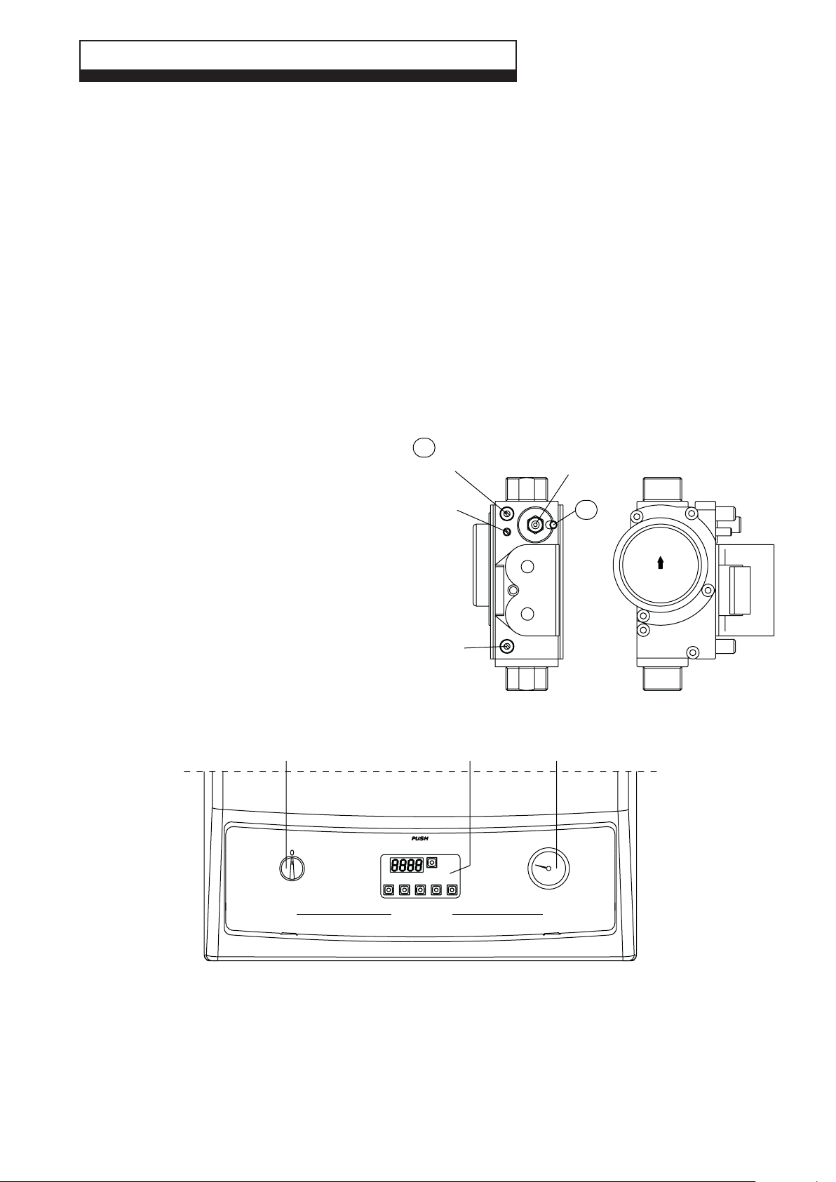
2. Loosen the gas inlet pressure test point screw
on the gas valve (see Fig. 23). Ensure the gas
supply is on and open the boiler service cock to
purge in accordance with BS 6891.
3. Retighten the test point screw and test for gas
tightness. Close the boiler gas service cock.
P3
Outlet gas
pressure
test point
Outlet flow
regulator
Off-set
adjusment
screw
P1
Inlet gas
pressure
test point
Fig. 23
5.3 BOILER CONTROLS - Fig. 24
On/Off switch
ON
RESET
MODE
STEP
STORE
-
+
Alpha
Pressure gaugeDisplay panel
Fig. 24
5.4 INITIAL LIGHTING - Refer to Fig. 24
1. Ensure that the gas and electrical supplies to the boiler are off and that the heating flow and return valves are open.
2. Turn on the gas and electrical supplies to the boiler.
3. Ensure any external controls are calling for heat.
4. Set the On/Off switch to ON. The boiler will now run in the central heating mode. The pump will start, the fan will start
and the main gas valve solenoid will open allowing the main burner to light.
Alpha CD50S/70S - Commissioning
19
Page 20
5.5 BOILER DISPLAY PANEL AND FUNCTION MODES
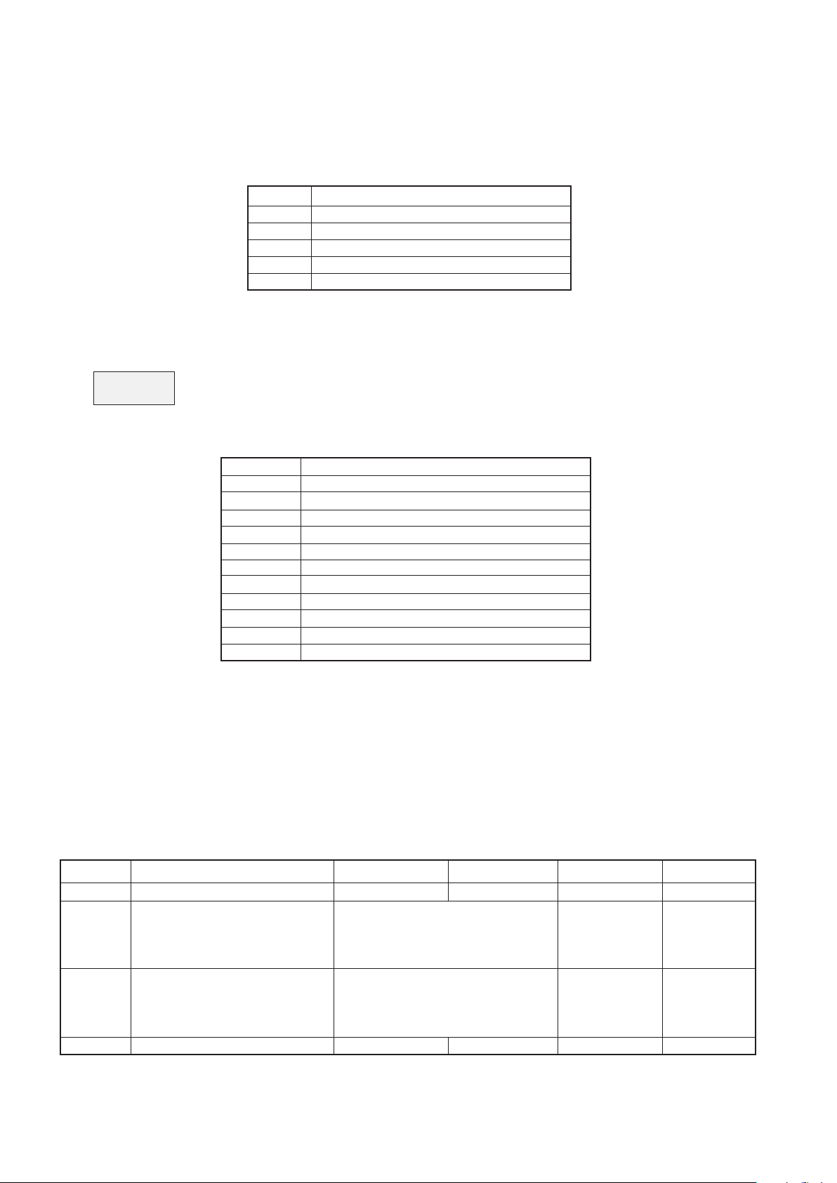
The boiler display panel (see Fig. 24, is composed of a 4-character display and 6 keys. By using these keys it is possible
to adjust the boiler as it would be by using traditional selector switches and knobs.
Table 2 gives the function of each key.
RESET
MODE
STEP
STORE
+
-
Manual reset for possible boiler block
Display menu selection key
Selection of parameter to be displayed or edited
Data and storage confirmation key
Increase set value
Decrease set value
Table 2
When the boiler is operating, the 4-figure display indicates the mode code (by means of the first 2 figures on the left) and
the boiler flow temperature (by means of the other two figures on the right).
For example if these values are shown on the display it means that the boiler is operating in
03 60
The boiler function modes are given in Table 3:
heating mode with a flow temperature of 60°C.
Mode code
0
1
2
3
4
5
6
7
8
9 (flashing)
A
Mode description
Stand - by, no operation demand
Pre-ventilation
Burner ignition
Burner lit (system heating)
Burner lit (domestic hot water)
Fan check
Burner off, requested temperature reached
Pump over-run in system heating mode
Pump over-run in domestic hot water mode
Burner off for one of the reasons given in Table 8
3 - way valve check
Table 3
5.6 BOILER FUNCTIONING PARAMETERS - Refer to Fig. 22
PARAMETER Mode - Press the MODE key once to enter Parameter mode. In this mode the preset operational values
can be changed. The first two figures indicate the parameter number, the last two give the setting value. To change the
boiler settings proceed as follows:
1. Press the MODE key once to enter parameter mode, using the STEP key select the parameter to be changed.
2. Change the value using the + or - keys, press the STORE key to store the new value.
3. Press MODE to make the new value effective.
Parameters that can be modified are given in Table 4
Parameter Factory set
1
2
3
4
Domestic hot water setting value *
Domestic hot water functioning mode
Heating function mode
Max. heating flow temperature
Description
* Only active with hot water function enabled when external accessories are fitted.
Lower limit value Upper limit value New value
20°C
0 = disabled
1 = enabled
2 = disabled + continuous pump
3 = enabled + continuous pump
0 = disabled
1 = enabled
2 = disabled + continuous pump
3 = enabled + continuous pump
20°C
70°C
85°C
20°C
0
1
85°C
Alpha CD50S/70S - Commissioning
20
Table 4
Page 21
Parameter 1: Allows domestic hot water temperature to be set if controlled with NTC probe.
Parameter 2: Allows domestic hot water production to be activated or cut out. With factory settings domestic hot water
production is cut out.
Parameter 3: Allows system heating function (Summer) to be cut out, or enabled (Winter). With factory settings system
heating is on.
Parameter 4: Allows heating flow temperature to be set. If the external temperature probe is connected to the boiler, the
electronics automatically determine the ideal system water temperature. This parameter represents the
maximum temperature that the system delivery water can reach.
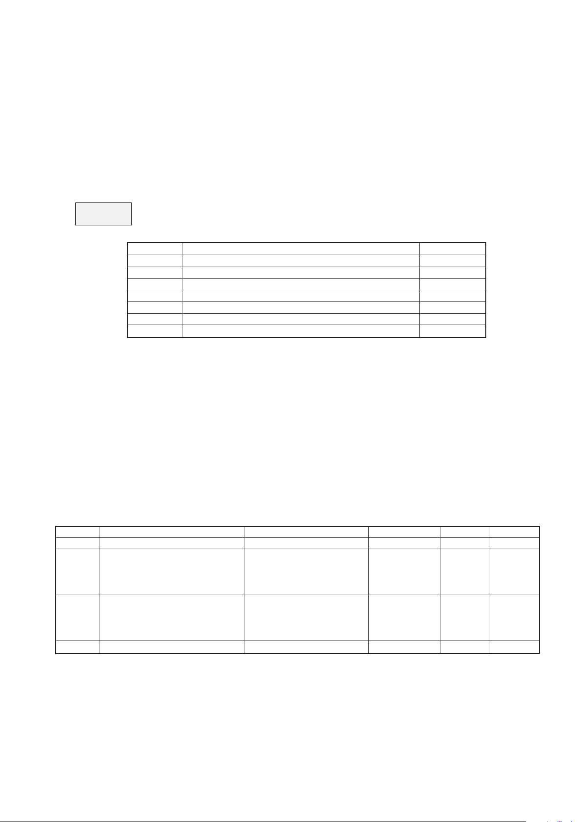
INFO Mode - Press the MODE key twice to enter INFO mode. In this mode the instantaneous operational values can be
displayed and checked, but without making changes. The first two figures indicate the step number; the last two give the
setting value.
For example if these values are shown on the display it means that the boiler is operating in
02 40
heating mode with a return temperature of 40°C.
Step
1
2
3
4
6
7, 8, 9
E
Visulisation
Flow temperature
Return temperature
Not active (Domestic temp., if domestic circuit probe is present)
Not active (External temp., if probe is installed)
Flow temperature set point
Temperature gradients (cannot be modified)
Flame current value
Value
Value in °C
Value in °C
70 (value in °C)
-37 (value in °C)
Value in °C
°C/S
µA
Table 5
5.7 BOILER FUNCTIONING PARAMETERS
Tables 6 and 7 gives the boiler adjustment parameters with factory settings. To modify the parameters reserved for the
Installer, it is necessary to enter an access code, which can be supplied on request.
To enter the code:
1. Press the MODE and STEP keys at the same time for 2 seconds; the display will show the wording CODE and
subsequently a random number on the last two digits.
2. Change the value by operating the + or - keys until reaching the correct code.
3. Press the STORE key to confirm.
Possible settings for the Installer and User (without entering an access code)
Parameter
1
2
3
4
Description
Domestic hot water set point value
Domestic hot water functioning mode
Central heating functioning mode
Max, central heating flow temperature
Lower limit value
20°C
0 = disabled
1 = enabled
2 = disabled + continuous pump
3 = enabled + continuous pump
0 = disabled
1 = enabled
2 = disabled + continuous pump
3 = enabled + continuous pump
20°C
Upper limit value
70°C
85°C
Factory set
20°C
0
1
85°C
New value
Table 6
Alpha CD50S/70S - Installation
21
Page 22

Parameter
10
11
12
13
14
15
16
17
18
19
20
21
22
23
24
25
26
27
28
29
30
31
32
33
34
35
36
37
38
39
40
41
42
43
44
45
46
47
48
Settings accessible by the Installer only
Description
Minimum heating flow temperature
Lower external temperature limit
Upper external temperature limit
Antifreeze temperature
External probe reading correction
Max. secondary heating circuit temperature
Min. secondary heating circuit temperature
Secondary heating circuit temp hysteresis
Min. tempearature set point value
Booster time
Flow temp compensation with ambient temp
Temp increase rel to DHW set point
Max fan rpm in heating mode (x100)
Max fan rpm in heating mode (units)
Max fan rpm in DHW mode (x100)
Max fan rpm in DHW mode (units)
Min fan rpm in heating mode (x100)
Min fan rpm in heating mode (units)
Fan rpm during ignition (x100)
Fan rpm during stabilisation period (x100)
Stabilisation period
Heating mode ramp up
Pump overrun at end of heating cycle
Pump overrun at end of DHW cycle
Hysteresis modulation with heating ON
Hysteresis modulation with heating OFF
Hysteresis modulation with DHW ON
Hysteresis modulation with DHW OFF
Hysteresis measurement with DHW ON
Hysteresis measurement with DHW OFF
Heating mode timer
DHW timer
DHW heating mode transition timer
Max time with DHW prioritised
Cascade address
Control type for heating installation
Type of DHW installation
Manual fan speed
PWM signal level for pump
Lower limit value
15°C
-30°C
15°C
-30°C
-5°C
Not active
Not active
Not active
0 = Off
1°C
0 = no booster
1 minute
0°C
0
15
0
15
0
12
0
21
12
0
0
0 = 10
1 minute
0 seconds
0°C
0°C
-5°C
0°C
0°C
-5°C
0
0
0 = phase with burner on
30 = phase with burner off 10 s
0 min
Not active
00 = ambient temp stat
01 = external probe
02 = 0 - 10 V power
03 = 0 - 10 V temperature
00 = instantaneous with probe
01 = instantaneous no probe
02 = Boiler with probe
03 = Boiler without probe
1 = Off
0%
1
Upper limit value
60°C
10°C
25°C
10°C
5°C
60°C
30 minutes
80°C
30°C
60
99
38
99
60
99
27
38
900
15
99 minutes
300 seconds
20°C
10°C
30°C
30°C
30°C
30°C
300 seconds
300 seconds
120 min
100%
4
Factory set
20°C
-5°C
20°C
0°C
0°C
0°C
0°C
0°C
15°C
CD50S=52
CD70S=53
0
38
0
CD50S=13
CD70S=15
0
23
CD50S=16
CD70S=17
06
2
3
60
0°C
5°C
0°C
5°C
5°C
0°C
180
0
0
0 min
00
02
-1
Not active
New value
Alpha CD50S/70S - Installation
22
Table 7
Page 23

Parameter
49
50
51
52
53
54
55
56
57
Description
PWM signal level for pump
PWM signal level for pump
PWM hysteresis
PWM pump high/low level
Low/Off and pump cycle
Min rpm for pressure switch (x100)
Min temp for boiler maintain function
Ramp up for HTG or HTG + DHW function
Pre-ignition time
Lower limit value
10
15
1°C
16
x0 = Off
x1 = On
0x = Normal heating pump cycle
0x = Normal DHW pump cycle
5
0°C
0 (heating only)
Not active
Upper limit value
50
50
10°C
255
70
80°C
1 (HTG + DHW)
Factory set
Not active
Not active
Not active
Not active
00
5
0°C
0
New value
Table 7 - continued
5.8 FINAL COMMISSIONING
1. Allow the heating system to heat up, then balance the system to achieve the necessary temperature difference
across the heating flow and return pipes at the boiler and check the system volume and pressure. (Refer to
Technical Data, Section 2.2).
2. Turn off the boiler.
4. Thoroughly flush out the water pipework (refer to Section 3.10).
5. Re-pressurise the system as described in Section 5.1.
5.9 FINAL ASSEMBLY
1. Raise and secure the control panel, replace the front cover and secure in position with the screws removed and
secure the plastic top cover in position using the screws previously removed.
2. If the boiler is to be left in service with the User, set any external controls to the User's requirements.
3. If the boiler is not to be handed over immediately, close the boiler gas service cock and switch off the electrical
supply.
4. If there is any possibility of the boiler being left during frost conditions, then the boiler and system should be drained. It is recommended
that a label is attached to the boiler drawing attention to the fact that the system has been drained.
5. Complete the details of the installation in the Benchmark Checklist on page 32.
5.10 USER INFORMATION
The User must be advised (and demonstrate if necessary) of the following important points:-
1. How to light and turn off the boiler and how to operate any external system controls.
2. The importance of annual servicing of the boiler to ensure safe and efficient operation.
3. That any servicing or replacement of parts must only be carried out by CORGI registered personnel.
4. Ensure that the boiler controls are set to the User's requirements.
5. Tell the User about the sealed system pressure.
6. Tell the User that if the electrical supply is on and the boiler has not operated for 24 hours for heating or hot water,
the pump will automatically operate for 5 minutes.
7. Explain to the User that an internal frost thermostat is fitted in the boiler, and that the electrical supply to the boiler
must be left on for the thermostat to operate, i.e. the On/Off switch must be set to ON.
8. Explain to the User that in certain weather conditions the terminal will emit a plume of steam, i.e. water vapour. This
is safe and quite normal.
9. Show the User the position of the pressure relief valve and condensate discharge pipes.
10. Hand the User's instructions to the User.
11. Ensure the Benchmark Checklist on page 32 has been completed after the boiler has been installed and
commissioned.
Note: It is a requirement that the installation is registered by the installer through the CORGI Gas Work Notification
Scheme.
12. Leave these Installation and Servicing instructions with the User for use on future calls.
Alpha CD50S/70S - Commissioning
23
Page 24

6 ROUTINE SERVICING
To ensure efficient operation of the boiler it is recommended that it is checked and serviced as necessary at regular
intervals. The frequency of servicing will depend upon the particular installation conditions and usage, but in general once
per year should be adequate.
It is the law that any service work must be carried out by a competent person, i.e. CORGI registered personnel.
Warning: Before servicing the boiler, isolate the electrical supply and close the boiler gas service cock. Allow the boiler to
cool.
The data label is positioned on the inside of the right hand of the base plate.
Always test for gas tightness after servicing any gas carrying components.
Always carry out electrical system checks i.e. Earth Continuity, Resistance to Earth, Short Circuit and Polarity with a
suitable meter after servicing.
Notes: 1. Prior to servicing, it is recommended that a flue gas analyser is used to measure the performance of the boiler
(refer to Fig. 3 or 4 for the position of the flue sampling point). If the CO/CO2 ratio measured is greater than
0.003 or when other checks and comments from the customer have indicated that there may be problems,
cleaning of the heat exchanger will be necessary. All Sections 6.1, 6.2, 6.3 and 6.4 must be carried out.
Repeat the flue gas analyser test after reassembling the boiler and check that the CO/CO2 ratio is less than
0.003.
2. If the CO/CO2 ratio measured is less than 0.003 and other checks and comments from the customer suggest
there are no problems then only Section 6.1 and Section 6.2 paragraphs 1, 2 and 3 need to be carried out to
allow a visual check of the components within the combustion chamber.
3. If a flue gas analyser is not available, then all Sections 6.1, 6.2, 6.3 and 6.4 must be carried out.
6.1 IMPORTANT NOTES PRIOR TO SERVICING
1. Check the flue terminal outside and ensure it is not blocked.
2. Run the boiler and check the operation of its controls.
3. Refer to Fig. 3 or 4 for location of flue sampling point.
4. Ensure that all system connections and fittings are sound.
5. Refill, vent and re-pressurise the system as necessary. (Refer to Commissioning, Section 5.1).
If the system pressure exceeds 3.5 bar when operating at maximum temperature, the heating expansion vessel
should be checked and re-pressurised, if necessary.
Note: Check the expansion vessel charge only when the system pressure is zero.
6. Check that the condensate trap drain pipe is connected and all joints are sound.
7. Record details of the service in the Service Record Section on page 33.
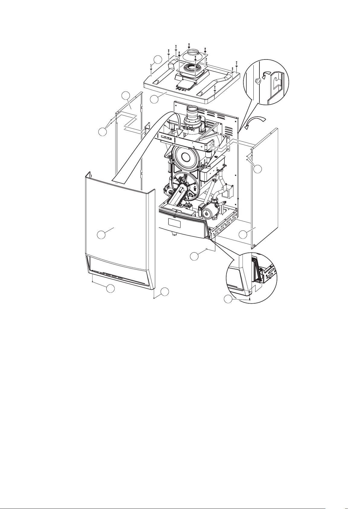
6.2 CASING REMOVAL - Fig. 25
If required, the casing can be completely removed as follows:
1. Remove the bottom cover plate by removing its four fixing screws.
2. Remove the two screws (item 1) securing the bottom of the casing front panel (item 5).
3. Remove the screws (item 7) at the top of the cover (item 6).
4. Pull the bottom of the casing front panel outwards while pushing upwards at the same time to remove it from the
boiler.
5. Remove the two screws (item 2), each side, securing the side panels to the front support bracket.
6. Remove the screws (item 3) at the bottom side of the boiler securing the bottom of the side panel (item 4), then push
upwards in order to remove the side panel.
Note: If only the front panel is to be removed, remove the four screws securing the plastic top cover so that it can be lifted
slightly at the front edge. Remove the two fixing screws (item 1) (one each side at the bottom) securing the case front
panel. Pull the bottom of the panel outwards while pushing up at the same time and remove the panel
Alpha CD12S/20S/28S - Routine Servicing
24
Page 25
7
4
6
2
2
5
4
3
1
1
1
Fig. 25 - Case removal (CD70S shown)
6.3 PREPARE FOR SERVICING - Fig. 26 or 27
1. Ensure the electrical supply is isolated and the gas supply is off.
2. Remove the complete case or just the front panel as described in Section 6.2.
4. Disconnect the gas supply pipe union from the burner manifold.
5. Remove the two screws securing the fan assembly to the combustion chamber front.
6. Remove the pressure tube.
7. Disconnect the electrode lead from the ignition generator and the in-line connector to the flame sensing electrode.
8. Remove the six nuts and washers securing the combustion chamber front assembly and remove the assembly.
Alpha CD12S/20S/28S - Routine Servicing
25
Page 26
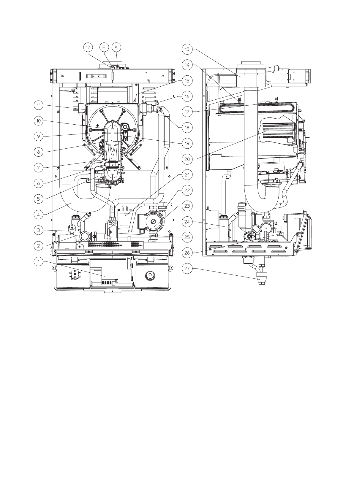
1 PCB
2 Delivery manifold
3 System pressure switch
4 Air intake pipe
5 Fan
6 Injecter
7 Venturi
8 Ignition sensor
9 Combustion chamber front cover
10 Venturi housing
11 Condensing heat exchanger
12 Test points (air A) - (flue F)
13 Flue hood
14 Primary return NTC
Alpha CD12S/20S/28S - Routine Servicing
26
15 Flue thermostat
16 Manual air vent
17 Primary flow NTC
18 Overheat thermostat
19 Ignition electrodes
20 Burner
21 Transformer
22 Automatic air vent
23 Pump
24 Condensate trap
25 Gas valve
26 Safety valve 4 bar
27 Tundish
Fig. 26 CD50S
Page 27
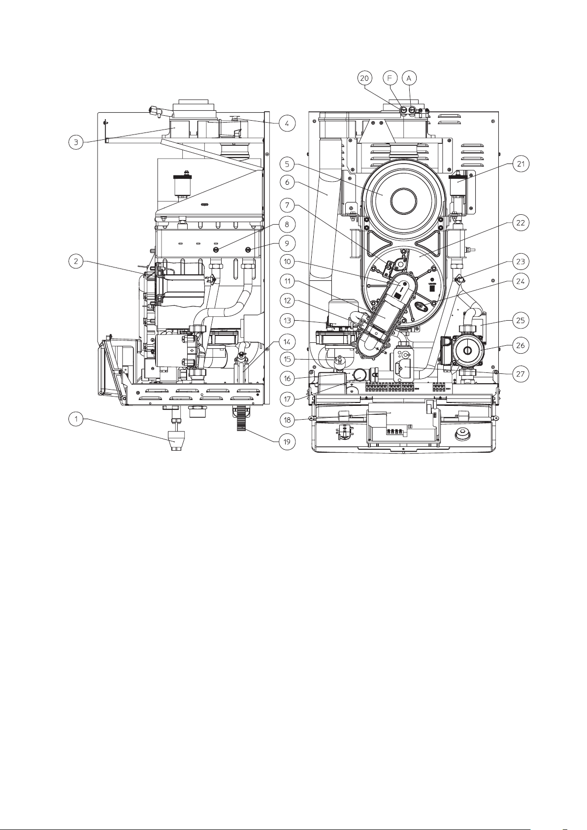
1 Tundish
2 Burner
3 Flue hood
4 Flue overheat thermostat
5 Condensing heat exchanger
6 Air intake pipe
7 Ignition electrode
8 Primary flow NTC
9 Primary return NTC
10 Venturi housing
11 Venturi
12 Injector
13 Fan
14 Condensate trap
15 System pressure switch
16 Flow manifold
17 Safety valve 4 bar
18 PCB
19 Condensate drain pipe
20 Test points (air A) - (flue F)
21 Automatic air vent
22 Combustion chamber front cover
23 Overheat thermostat
24 Ignition sensor
25 Transformer
26 Pump
27 Gas valve
Fig. 27 CD70S
Alpha CD12S/20S/28S - Routine Servicing
27
Page 28
6.4 CLEANING THE BOILER
1. Remove any deposits from heat exchanger using a suitable soft brush. Do not use a brush with metallic bristles.
2. Check the condition of the combustion chamber insulation panels.
3. Check the condition of the burner injector on the combustion chamber front assembly, carefully clean them with a
soft brush if necessary.
Do not use a brush with metallic bristles as this might damage the injector.
4. Remove any deposits from the heat exchanger coils. This can be done by suction or water sprayed onto the coils.
Ensure all electrical components are protected from water. Any water used to clean the heat exchanger will drain to
the condensate trap.
5. Unscrew and replace the injector should it appear damaged.
6. Remove the four screws securing the burner and remove the burner. Clean the burner with a soft brush and check
that the flame ports are clear. Blockages may be removed with a stiffer brush. Tap the burner, open end down, to
remove any deposits from inside.
7. Check the condition of the electrodes.
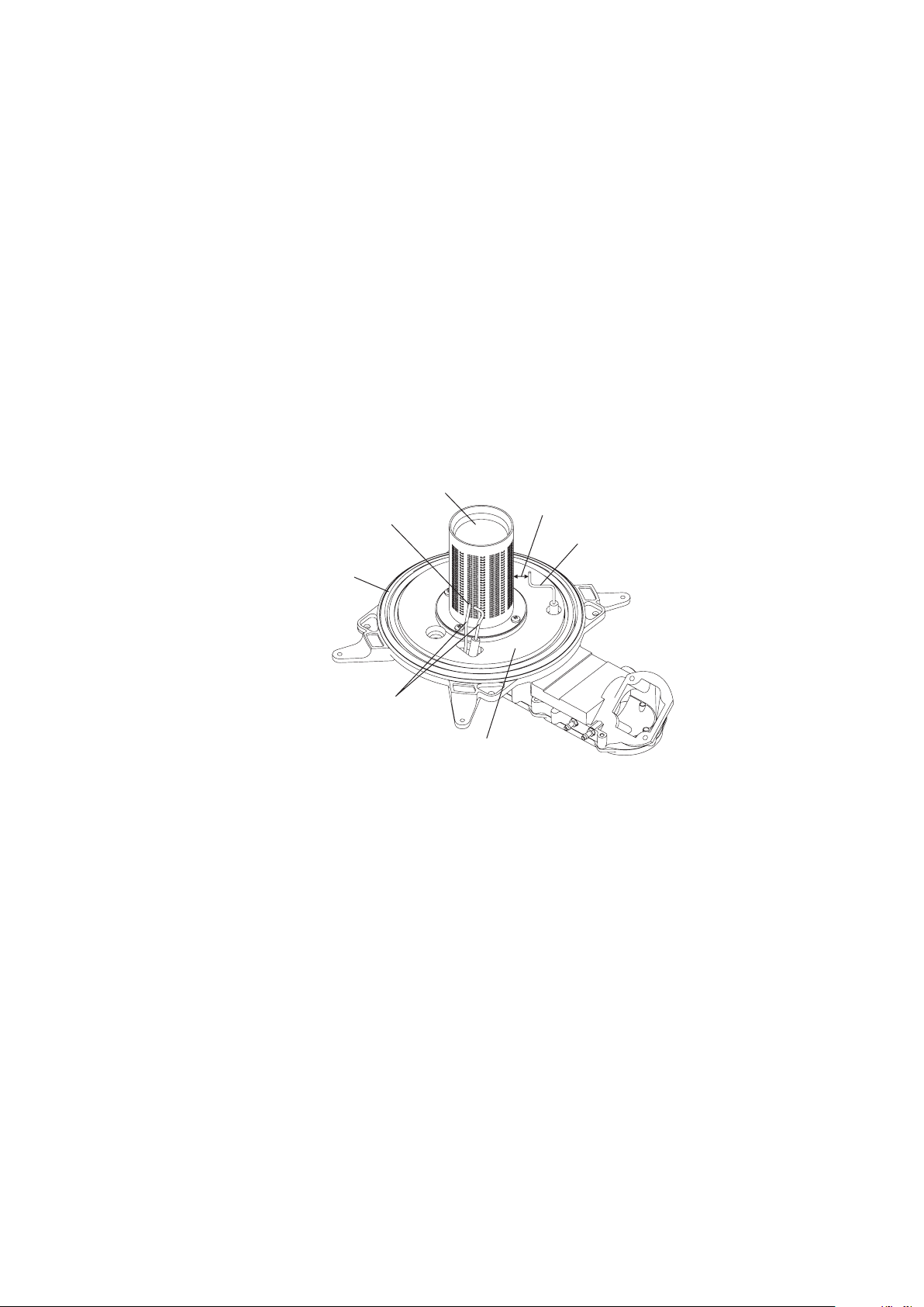
9. Check the spark gap, positioning and height of the electrodes. Refer to Fig. 28.
10. Unscrew the condensate trap drain cap to remove any deposits.
Note: Before removing the cap, ensure that the water released from the trap can be contained to avoid spillage.
The trap will contain no more than 200 cc of condensate water. Replace the drain cap.
Burner
Electrode gap
3-4mm
Combustion chamber
front assembly
Ignition electrodes
Front panel insulation
Burner to electrode
gap 16 mm
Flame sensing
electrode
Fig. 28
6.5 RE-ASSEMBLE THE BOILER
1. Replace the burner, ensuring it is located correctly and secure it in position using the four screws previously
removed.
Important: Before replacing the combustion chamber front assembly, pour at least 200 cc of water into the coils of
the heat exchanger. This is to ensure the condensate trap is full of water before operating the boiler.
2. Replace the combustion chamber front assembly, ensuring it is correctly located.
3. Ensure the electrode lead is connected.
4. Re-connect the gas pipe to the manifold, test the connections for gas tightness and re-commission, Sections 5.2 and
5.4.
5. Place the case or front case panel in position and secure in position with the screws previously removed, see
Section 6.2.
7. Check the operation of the boiler.
8. Return all controls to their original settings.
Alpha CD50S/70S - Routine Servicing
28
Page 29
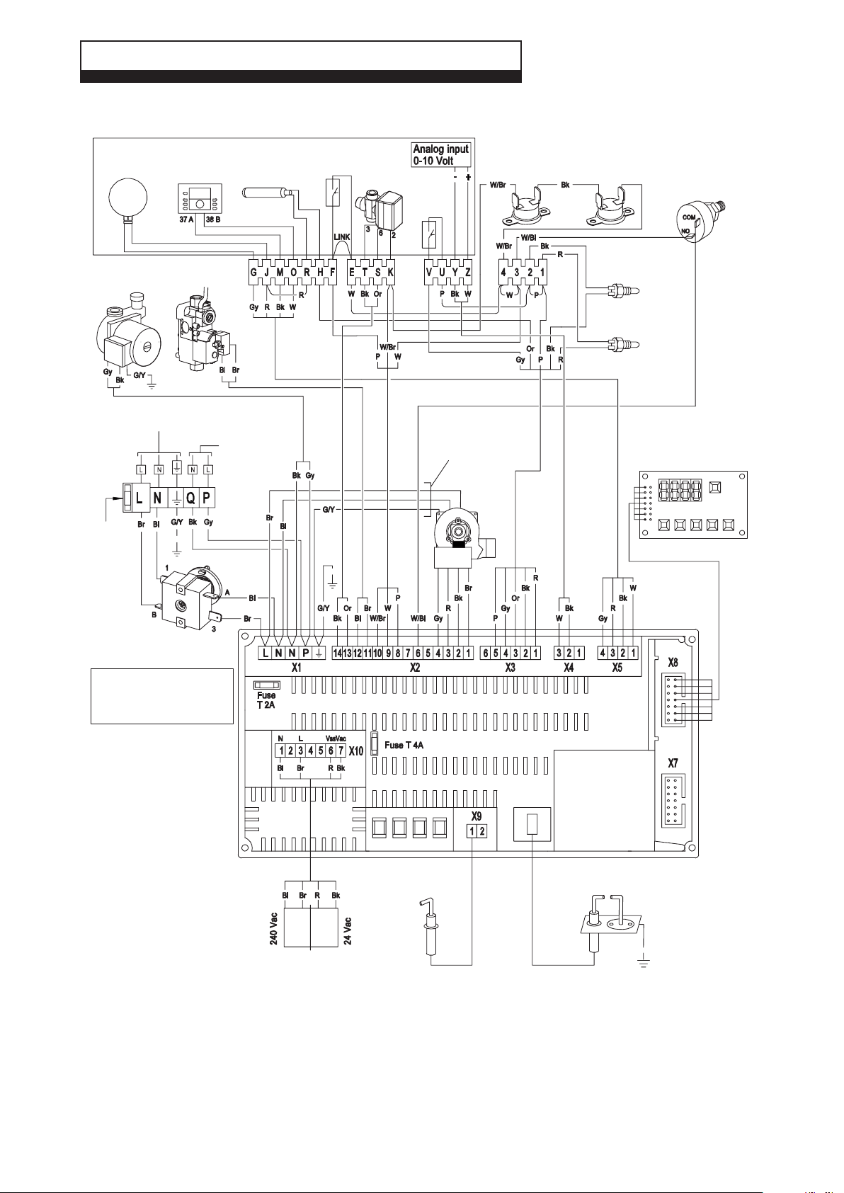
7 WIRING DIAGRAM
Optional controls - Note: maximum 24 volt only. Do not connect 230/240 volts
External
probe
Cascade
regulator
DHW
temperature
sensor
thermostat
Room
Diverter
valve
motor
thermostat
Summer
switch
Overheat
Flue overheat
thermostat
System pressure
switch
Pump
230/240 V ~ 50 HZ Fused at 2 A
Fuse
F 2 A
Gas valve
Supply
External pump
X85
Selector
Max 1 A
X86
CD70S only
Fan
X84
temperature sensor
temperature sensor
Return
Heating flow
Display
NOTE: to apply an external
room thermostat, connect it
to the terminals F & E
removing the link.
Br Brown
Bk Black
Bl Blue
R Red
Or Orange
G/Y Green/Yellow
W White
GY Grey
P Purple
W/Bl White/Blue
W/Br White/Brown
Transformer
Flame sensing
electrode
Fig. 29
Ignition electrodes
Alpha CD50S/70S - Wiring Diagram
29
Page 30
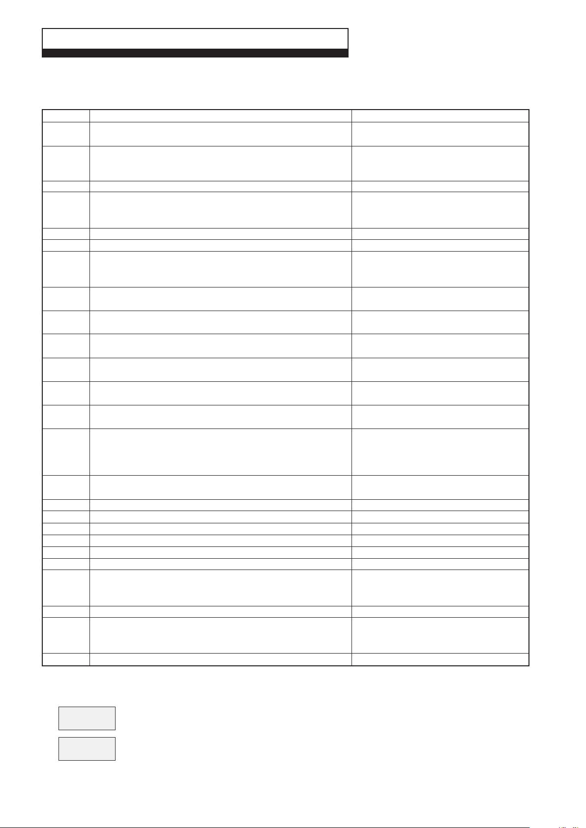
8 F AULT FINDING
Boiler error codes that may appear on the right hand side of the boiler display panel when a fault shuts down the boiler.
The code will be displayed with either the letter 'E' or 'b' on the left hand side.
'E' codes require a manual reset, 'b' codes will automatically reset.
Code
00
02
03
05 06 11
13 14 15
16 17 44 60
04
07
12
18
19
24
25
26
28
29
30
31
32
33
36
37
38
65
114
118
FUSE
Description
Flame sensor fault detected
Ignition failure
Gas valve supply error
Internal fault (electronics)
Burner lock-out (electrical fault)
Gas valve relay fault
Overheat safety thermostat operated
Primary flow temperature too high
Primary return temperature too high
Return temp. higher than flow temp. by more than 10°C after 180 sec
Rapid primary flow temperature increase
Insufficient water pressure
Fan fault (no Hall signal)
Fan fault
Temperature difference between system flow and return too high
Primary flow temperature sensor fault (short circuited)
Primary return temperature sensor fault (short circuited)
Domestic temperature sensor fault (short circuited)
System flow sensor fault (open)
System return sensor fault (open)
Domestic circuit sensor fault (open)
Fan fault (insufficient air)
Invalid cascade signal
Loss of ionisation current during ignition of burner
(after 3 attempts fault becomes error 02)
24 V fuse blown (T 4A)
Solution
Check flame sensing electrode and wiring
Check PCB
Check gas supply
Check electrode position
Check flame sensing signal is greater than 6µA
Check gas supply
Check electrical connections
Check PCB
Check electrical connections
Check electrical connections
Check PCB fuses
Check primary flow thermostat
Check flue thermostat
Check water circulation
Check for air in the system
Check water circulation
Check for air in the system
Check water circulation
Check for air in the system
Check water circulation
Check for air in the system
Check for system leaks
Re-pressurise the system 0.75 - 1.25 bar
Check fan
Check fuse F3
Check fan
Check fuse F3
Check electrical connections
Check PCB
Check water circulation
Check for air in the system
Check NTC resistance
Check NTC resistance
Check NTC resistance
Check NTC resistance
Check NTC resistance
Check NTC resistance
Check fan
Check flue
Check air inlet pipework
Check correct address setting on PCB
Check gas supply
Check gas supply pressure
Check gas supply pipework
Change fuse
Examples of boiler error codes
This example of a manual reset fault means that the boiler has ignition failure. To eliminate the
E 02
failure press the RESET button on the boiler control panel (see Fig. 24).
This example of an automatic reset fault means that the temperature difference between the
6 30
system flow and return is more than 40°C. The boiler will automatically reset when the anomaly
disappears.
Alpha CD50S/70S - Fault Finding
30
Table 8
Page 31

9 SHORT PARTS LIST
Description
Main PCB
Display PCB
Control panel flap
Control panel - CD50S
Control panel - CD70S
Pressure gauge
Transformer
Flame sensor
Flame sensor lead
Ignition electrodes and lead
Combustion chamber cover - CD50S
Combustion chamber cover - CD70S
Burner - CD50S
Burner - CD70S
Injector Nat Gas - CD50S
Injector Nat Gas - CD70S
Injector LPG - CD50S
Injector LPG - CD70S
Fan - CD50S
Fan - CD70S
Flexible air inlet pipe - CD50S
Flexible air ilnet pipe - CD70S
Primary Heat exchanger _ CD50S
Primary heat exchanger - CD70S
Plastic flue manifold - CD50S
Plastic flue manifold - CD70S
Primary NTC
Pump - CD50S
Pump - CD70S
Automatic air vent - CD50S
Automatic air vent - CD70S
Primary pressure switch
Gas valve - CD50S
Gas valve - CD70S
Expansion relief valve
Flow manifold
Overheat thermostsat
Flue thermostat - CD50S
Flue thermostat - CD70S
Pipe, pump to heat exchanger - CD50S
Pipe, pump to heat exchanger - CD70S
Pipe, heat exchanger to manifold - CD50S
Pipe, heat exchanger to manifold - CD70S
Pipe, gas valve to burner manifold - CD50S
Pipe, gas valve to burner manifold - CD70S
LH side panel
RH side panel
Flow/return adapter 1 1/2"
Tundish
Pipe, tundish adapter
Qty.
1
1
1
1
1
1
1
1
1
1
1
1
1
1
1
1
1
1
1
1
1
1
1
1
1
1
1
1
1
1
1
1
1
1
1
1
1
1
1
1
1
1
1
1
1
1
1
1
1
1
Alpha Pt. No.
1.025819
1.019405
1.018884
1.027173
1.027180
1.015807
1.025780
1.026474
3.019870
3.019718
1.025506
1.024139
1.017499
1.025333
1.019802
1.025283
1.019818
1.026051
1.021206
1.023299
1.019313
1.024266
1.022167
1.024241
3.017115
3.017475
1.023435
1.021532
1.024234
1.019735
1.2295
1.021715
1.019556
1.024263
1.018879
1.024184
1.016870
1.012067
1.021356
1.025017
1.024282
1.027141
1.024289
1.018784
1.024264
2.012075
2.012074
3.019369
1.018870
1.011654
Alpha CD50S/70S - Short Parts List
31
Page 32
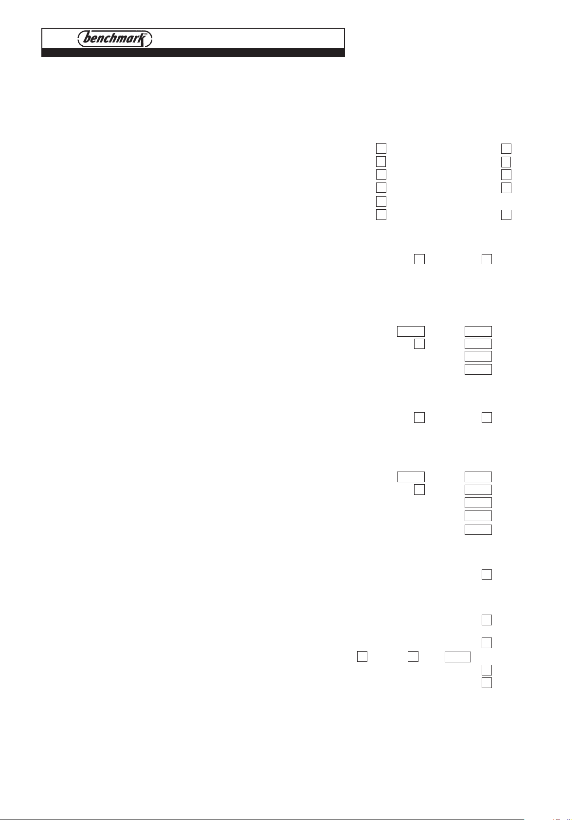
10 CHECKLIST
Ensure the following is completed after the boiler has been installed and commissioned:-
BOILER SERIAL No. ......................................................... NOTIFICATION No. ..........................................................
CONTROLS
Time & temperature control to heating
Time & temperature control to hot water
Heating zone valves
Hot water zone valves
Thermostatic radiator valves
Automatic by-pass to system
FOR ALL BOILERS CONFIRM THE FOLLOWING:
The system has been flushed in accordance with the boiler manufacturer's instructions? Yes No
The system cleaner used ........................................................................................................ ............
The inhibitor used................................................................................................................................
FOR CENTRAL HEATING MODE, MEASURE AND RECORD THE FOLLOWING:
Gas rate m³/hr ft³/hr
Burner operating differential pressure (if applicable) N/A mbar
Central heating flow temperature °C
Central heating return temperature °C
FOR COMBINATION BOILERS ONLY
Has a water scale reducer been fitted? Yes No
What type of scale reducer has been fitted?......................................................................................
To comply with the Building Regulations, each section must have a tick in one or other of the boxes
room t/stat & programmer/timer
cylinder t/stat & programmer/timer
Fitted
Fitted
Fitted
Fitted
Programmable roomstat
Combi boiler
Not required
Not required
Not required
FOR DOMESTIC HOT WATER MODE, MEASURE AND RECORD THE FOLLOWING:
Gas rate m³/hr ft³/hr
Maximum burner operating differential pressure (if applicable) N/A mbar
Cold water inlet temperature °C
Hot water outlet temperature °C
Water flow rate lts/min
FOR CONDENSING BOILERS ONLY CONFIRM THE FOLLOWING:
The condensate drain has been installed in accordance with the manufacturer's instructions? Yes
FOR ALL INSTALLATIONS CONFIRM THE FOLLOWING:
The heating and hot water system complies with current Building Regulations Yes
The appliance and associated equipment has been installed and commissioned
in accordance with the manufacturer's instructions Yes
If required by the manufacturer, have you recorded a CO/CO
The operation of the appliance and system controls have been demonstrated to the customer Yes
The manufacturer's literature has been left with the customer Yes
COMMISSIONING ENG'S NAME:
Print...................................................................... CORGI ID No...................................................
ratio reading N/A Yes CO/CO2 ratio
2
Sign ...................................................................... Date .................................................................
Alpha CD50S/70S - Benchmark Checklist
32
Page 33

11 SERVICE RECORD
It is recommended that your heating system is serviced regularly and that you complete the appropriate Service Interval
Record below.
Service Provider: Before cpmpleting the appropriate Service Interval Record below, please ensure you have carried out
the service as described in this instruction manual. Always use the manufacturer's specified spare parts when replacing
all controls.
SERVICE 1: Date .......................................................................
Engineers Name .........................................................................
Company Name ..........................................................................
Telephone No..............................................................................
CORGI ID card serial No. ...........................................................
Comments ...................................................................................
.....................................................................................................
Signature .....................................................................................
SERVICE 3: Date .......................................................................
Engineers Name .........................................................................
Company Name ..........................................................................
Telephone No..............................................................................
CORGI ID card serial No. ...........................................................
Comments ...................................................................................
.....................................................................................................
Signature .....................................................................................
SERVICE 2: Date .......................................................................
Engineers Name .........................................................................
Company Name ..........................................................................
Telephone No..............................................................................
CORGI ID card serial No. ...........................................................
Comments ...................................................................................
.....................................................................................................
Signature .....................................................................................
SERVICE 4: Date .......................................................................
Engineers Name .........................................................................
Company Name ..........................................................................
Telephone No..............................................................................
CORGI ID card serial No. ...........................................................
Comments ...................................................................................
.....................................................................................................
Signature .....................................................................................
SERVICE 5: Date .......................................................................
Engineers Name .........................................................................
Company Name ..........................................................................
Telephone No..............................................................................
CORGI ID card serial No. ...........................................................
Comments ...................................................................................
.....................................................................................................
Signature .....................................................................................
SERVICE 7: Date .......................................................................
Engineers Name .........................................................................
Company Name ..........................................................................
Telephone No..............................................................................
CORGI ID card serial No. ...........................................................
Comments ...................................................................................
.....................................................................................................
Signature .....................................................................................
SERVICE 9: Date .......................................................................
Engineers Name .........................................................................
Company Name ..........................................................................
Telephone No..............................................................................
CORGI ID card serial No. ...........................................................
Comments ...................................................................................
.....................................................................................................
Signature .....................................................................................
SERVICE 6: Date .......................................................................
Engineers Name .........................................................................
Company Name ..........................................................................
Telephone No..............................................................................
CORGI ID card serial No. ...........................................................
Comments ...................................................................................
.....................................................................................................
Signature .....................................................................................
SERVICE 8: Date .......................................................................
Engineers Name .........................................................................
Company Name ..........................................................................
Telephone No..............................................................................
CORGI ID card serial No. ...........................................................
Comments ...................................................................................
.....................................................................................................
Signature .....................................................................................
SERVICE 10: Date .....................................................................
Engineers Name .........................................................................
Company Name ..........................................................................
Telephone No..............................................................................
CORGI ID card serial No. ...........................................................
Comments ...................................................................................
.....................................................................................................
Signature .....................................................................................
Alpha CD50S/70S - Service Record
33
Page 34

34
Page 35

35
Page 36

Alpha Therm Limited.
Nepicar House, London Road, Wrotham Heath,
Sevenoaks, Kent TN15 7RS
Tel: 0870 3001964
These instructions have been carefully prepared but we reserve the right to
alter the specification at any time in the interest of product improvement.
© Alpha Therm Limited 2008.
email: [email protected]
website:www.alpha-innovation.co.uk
Manual compiled and designed by Publications 2000 - Tel: (01670) 356211 06/08/D222
Part No. 1.027175
 Loading...