

Page 1
CESC Sidecar Installation Manual
Effective: March, 2004
®
Page 2

Alpha Technologies
Power
®
Page 3
CE Sidecar
Enclosure Installation Manual
031-106-C1-001, Rev. A
Effective Date: March, 2004
Copyright© 2004
Alpha Technologies, Inc.
NOTE: Alpha denies responsibility for any damage or injury involving its
enclosures, power supplies, generators, batteries, or other
hardware when used for an unintended purpose, installed or
operated in an unapproved manner, or improperly maint ained.
NOTE: Photographs contained in this manual are for illustrative purposes
only . These photographs may not exactly match your installation.
NOTE: Review the drawings and illustrations contained in this manual
before proceeding. If there are questions regarding the safe
operation of this powering system, please contact Alpha
T echnologies or your nearest Alpha representative.
Contacting Alpha Technologies:
For general product information and customer service
1-800-863-3930
(7:00 AM to 5:00 PM Pacific Time )
For complete technical support
1-800-863-3364
(7:00 AM to 5:00 PM Pacific Time, or 24/7 emergency support)
Page 4

TM
Table of Contents
1. Introduction .......................................................................... 9
2. Installation ......................................................................... 10
2.1 Concrete Pad Preparation ...................................... 10
2.2 Utility Power Connection .......................................11
2.3 Generator / Sidecar Inter-connecting Cables............15
2.4 Internal Components ............................................ 16
2.5 Battery Pack Wiring .............................................. 17
2.6 Power Supply Placement .......................................18
2.7 Battery Remote Temperature Sensor (RTS).............. 19
2.8 Service Power Inserter .......................................... 20
List of Figures
Fig. 1 Sidecar and generator enclosure ..........................9
Fig. 2 Pad layout....................................................... 10
Fig. 3 Service Entrance wiring ..................................... 13
Fig. 4 Meter base wiring .............................................14
Fig. 5 Interconnection wiring ...................................... 15
Fig. 6 Fan connections ............................................... 16
Fig. 7 Location of IPP, SPI, and ground rail ...................16
Fig. 8 36- & 48-volt battery string wiring ..................... 17
Fig. 9 Power supply on shelf ....................................... 18
Fig. 10 Location of temperature sensor ......................... 19
Fig. 11 Seizure screw assembly location ........................20
Fig. 12 Cable connection..............................................20
Fig. 13 Location of SPI ................................................ 20
List of Tables
Table 2-1 Circuit Breaker Requirements ........................ 11
4 031-106-C1-001 Rev. A
Page 5
Important Safety Instructions Contained in This
Manual
CAUTION
HAZARDOUS CONDITION
T o reduce the risk of electrical shock, injury or death caused by explosion of fuel or moving
parts, and to ensure the safe operation of this unit, the following symbols have been placed
throughout the manual. Where these symbols appear, servicing should be performed only
by qualified personnel.
DANGEROUS VOL TAGE
This symbol indicates a “dangerous voltage” exists in this area of the
product. Use caution whenever working in the area to prevent
electrical shock.
Preface
INHALATION HAZARD - DON’T BREATHE VAPORS
This symbol indicates an “inhalation hazard” exists in this area of the
product. Use caution whenever working in the area to prevent possible
inhalation of harmful (fuel or exhaust) vapors.
NO MATCHES OR OPEN FLAMES
This symbol indicates a fire or explosive hazard exists in this area of
the product. Use caution whenever working in the area to prevent
possible combustion fuel vapors.
MECHANICAL OR MOVING PARTS HAZARD
These symbols indicate the presence of a “mechanical or moving parts
hazard” in this area of the product. Use caution whenever working in
the area to prevent possible injury to the operator or service personnel.
LEAK HAZARD
This symbol indicates a “leak hazard” exists in this area of the product.
Use caution whenever working in the area to prevent and correct any
leaks detected.
CRUSH HAZARD
This symbol indicates the presence of crushing hazard in this area.
Keep hands clear of areas under extended battery trays and equipment
drawers.
ATTENTION
This symbol indicates important installation, operation or maintenance
instructions. Always follow these instructions closely.
5 031-106-C1-001 Rev . A
Page 6

Preface
A “Warning” identifies conditions and actions that pose a hazard to the user.
A “Caution” identifies conditions and actions that may damage the power
supply or associated equipment.
Warnings
NOTE: This power supply and its associated hardware (enclosure, batteries, cabling)
may contain equipment, batteries or parts which have accessible hazardous
voltage or currents.
T o avoid injury:
• This power supply and its associated hardware must be serviced by authorized personnel
only .
• The enclosure which contains the power supply and associated equipment must remain
locked at all times, except when authorized service personnel are present.
• Remove all conductive jewelry or personal equipment prior to servicing equipment, parts,
connectors, wiring, or batteries.
• Read and follow all installation, equipment grounding, usage, and service instructions
included in this manual.
• Use proper lifting techniques whenever handling equipment, parts, or batteries.
• Batteries contain dangerous voltages, currents and corrosive material. Battery installation,
maintenance, service and replacement must be performed by authorized personnel only .
• Never use uninsulated tools or other conductive materials when installing, maintaining,
servicing or replacing batteries.
• Use special caution when connecting or adjusting battery cabling. An improperly connected
battery cable or an unconnected battery cable can result in arcing, a fire, or possible
explosion.
• A battery that shows signs of cracking, leaking or swelling must be replaced immediately by
authorized personnel using a battery of identical type and rating.
• Avoid any contact with gelled or liquid emissions from a valve-regulated lead-acid (VRLA)
battery. Emissions cont ain dilute sulfuric acid which is harmful to the skin and eyes.
Emissions are electrolytic, which are electrically conductive and are corrosive. Follow the
Chemical Hazards notes if contact occurs.
• Do not smoke or introduce sparks in the vicinity of a battery .
6 031-106-C1-001 Rev. A
Page 7

Battery Safety Notes
Lead-acid batteries contain dangerous voltages, currents and corrosive material. Battery
installation, maintenance, service and replacement must be performed by authorized personnel
only.
Chemical Hazards
NOTE: Any gelled or liquid emissions from a V alve-Regulated lead-acid (VRLA)
battery contain dilute sulfuric acid, which is harmful to the skin and eyes.
Emissions are electrolytic, which are electrically conductive and
corrosive.
T o avoid injury:
• Wear protective clothing (insulated gloves, eye protection, etc) whenever installing,
maintaining, servicing, or replacing batteries.
• If any battery emission contacts the skin, wash immediately and thoroughly with water .
Follow your company’s approved chemical exposure procedures.
Preface
• If any battery emission contacts the eye, wash immediately and thoroughly with water for
10 minutes with pure water or a special neutralizing eye wash solution and seek
immediate medical attention. Follow your company’s approved chemical exposure
procedures.
• Neutralize any spilled battery emission with the special solution contained in an approved
spill kit or with a solution of 1 lb. bicarbonate of soda to 1 gal. of water. Report chemical
spill using your company’s spill reporting structure and seek medical attention if
necessary.
• Always replace batteries with those of an identical type and rating. Never install old or
untested batteries.
• Do not charge batteries in a sealed container . Each individual battery should have at least
0.5 inches of space between it and all surrounding surfaces to allow for convection
cooling.
• All battery compartments must have adequate ventilation to prevent an accumulation of
potentially dangerous gas.
7 031-106-C1-001 Rev . A
Page 8

Preface
Important Installation Notes
The system must be installed ONL Y by qualified service personnel.
Consult local utility codes for additional cabinet grounding and utility requirements.
ALPHA TECHNOLOGIES is not responsible for broken welds or other damage to the
cabinet caused by improper installation.
All dimensions are given in inches.
For further information regarding this installation, contact ALPHA TECHNOLOGIES or your
nearest ALPHA representative.
NOTE:
Alpha T echnologies’ products are subject to change
through continual improvement processes. Therefore,
specifications and/or design layouts may vary slightly
from descriptions included in this manual. Updates to the
manual will be issued when changes affect form, fit or
function.
Save these instructions for future reference
8 031-106-C1-001 Rev. A
Page 9

1. Introduction
1.1 Enclosure Introductions
The CESC enclosure is a cost effective 'all in one' power system. The side car provides for a
single power module, batteries, and generator in a low profile minimum footprint design.
This procedure describes the installation of a side car to an AlphaGen generator, PN-3B or
CE3X2B enclosure.
Fig. 1 Sidecar and Generator Enclosure
9 031-106-C1-001 Rev . A
Page 10

2. Installation
2.1 Concrete Pad Preparation
Pads can either be poured on site, or precast by Alpha T echnologies. The mounting holes on
the bottom of the high security PN-3 will fit both a standard PN-3 pad, and a CE3X pad.
Precast pad model number PCC-SC-3X, Alpha P/N 641-061-10 or PCD-SC-3X, Alpha P/N
641-064-10 (east coast) are available for this system.
19.5
5
5.5
9.2
3.5
CESC
6
22.0
14.7
Generator
or PN3/4
1
3.5
6.8
10.25
4
Fig. 2 Pad Layout
All measurements are indexed to the front left generator mounting stud.
1
Indicates outline of enclosure.
2
2
3
All Measurments
in Inches
Alpha standard; recommended distance (6" minimum) between edge of pad and cabinet.
3
Four inch diameter hole for AC power IN (non-metered installation).
4
All mounting hardware must be stainless, galvanized, or better to prevent corrosion.
5
5" x 8" rectangular cutout for all internal connections including: generator power and/or coax
6
cable conduit sweeps. Position between mounting studs not critical.
A 25+ year continuous vapor barrier must be used between the enclosure and the pad to
prevent moisture ingress and possible corrosion caused by metal to concrete contact.
The vapor barrier material (such as 30 lb felt, neoprene pond liner, or heavy grade t ar
paper) must be initially extended at least 6" in all directions around the perimeter of the
enclosure. Af ter the enclosure is secured to the pad, the material can be cut closer to
the enclosure, using the appropriate knife or cutting tool.
10 031-106-C1-001 Rev. A
Page 11

2. Installation
2.2 Utility Power Connection
CAUTION: The “Utility Power Connection” procedure must ONLY be performed by qualified
service personnel and in compliance with local electrical codes and common safety
practices. Connection to utility power must be approved by the local utility before
installing the power supply .
NOTE: UL and NEC require that a service disconnect switch (UL listed) be provided by the
installer and be connected between the power source and the ALPHA power supply .
Connection to the power supply must include an appropriate service entrance weather
head.
Wiring the Utility Service
NOTE: A “high-magnetic” trip circuit breaker must be used in order to accommodate the
high-inrush currents normally associated with the start-up of ferroresonant
transformers (400 Amp, no-trip, first half cycle). Do not replace this circuit breaker
with a conventional service entrance circuit breaker. Alpha recommends Square D
circuit breakers ONL Y , because of increased reliability in this powering application.
Alpha Technologies offers a high-magnetic Square D circuit breaker and a BBX option (a UL Listed
service entrance). Contact your local sales representative for more information.
Description
240V Installation — HACR (15A)
120V Installation — High-magnetic (20A)
120V Installation — High-Magnetic (15A)
BBX — External Service Disconnect
Alpha Part Number Square D Part Number
470-224-10
470-017-10
470-017-10
470-013-10
020-085-10
QO215
QO120HM
QO115HM
QO2-4L70RB
QO8-16L100RBBBX — External Service Disconnect 020-141-10
Table 2-1 Service Entrance Circuit Breaker Requirements
In most cases, the following configurations (see next page) qualify for service
entrance use, however, other codes may apply. Always contact your local utility to
verify that the wiring conforms to applicable codes.
11 031-106-C1-001 Rev . A
Page 12

2. Installation
2.2 Utility Power Connection, continued
240V AC Service (XM Series 2 915-240 Power Supply; XM Series 2 922-
120V AC 20A Service (XM Series 2 915-120 Power Supply): Enclosures used
48 for UPE-4 and UPE-8): Enclosures used with the XM
Series 2 915-240 or 922-48 are equipped with a 240V AC
duplex receptacle to provide power to the power supply
and peripheral equipment. The receptacle, NEMA 6-15R,
is protected by a single, 2-pole, common trip 15
Amp circuit breaker located inside the service entrance.
Wiring is typically 14AWG per NEC code, a grounding
clamp, located on the enclosure, facilitates dedicated
grounding.
with the XM Series 2 915-120 are equipped with a
120V AC duplex receptacle to provide power to the
power supply and peripheral equipment. The receptacle,
NEMA 5-20R, is protected by a single, 2-pole, common
trip 20 Amp circuit breaker located inside the service
entrance. Wiring is typically 12AWG per NEC code, a
grounding clamp, located on the enclosure, facilitates
dedicated grounding.
120V AC 15A Service (XM Series 2 615): Enclosures used with the XM Series
2 615 are equipped with a 120V AC duplex receptacle
to provide power to the power supply and peripheral
equipment. The receptacle, NEMA 5-15R, is protected
by a single-pole, 15 Amp High Magnetic circuit breaker
located inside the service entrance. Wiring is typically
14AWG per NEC code, a grounding clamp, located on
the enclosure, facilitates dedicated grounding.
NOTE: Alpha recommends wiring with 12AWG, in case the enclosure
is to be upgraded to use 90V power supplies in the future.
12 031-106-C1-001 Rev. A
Page 13

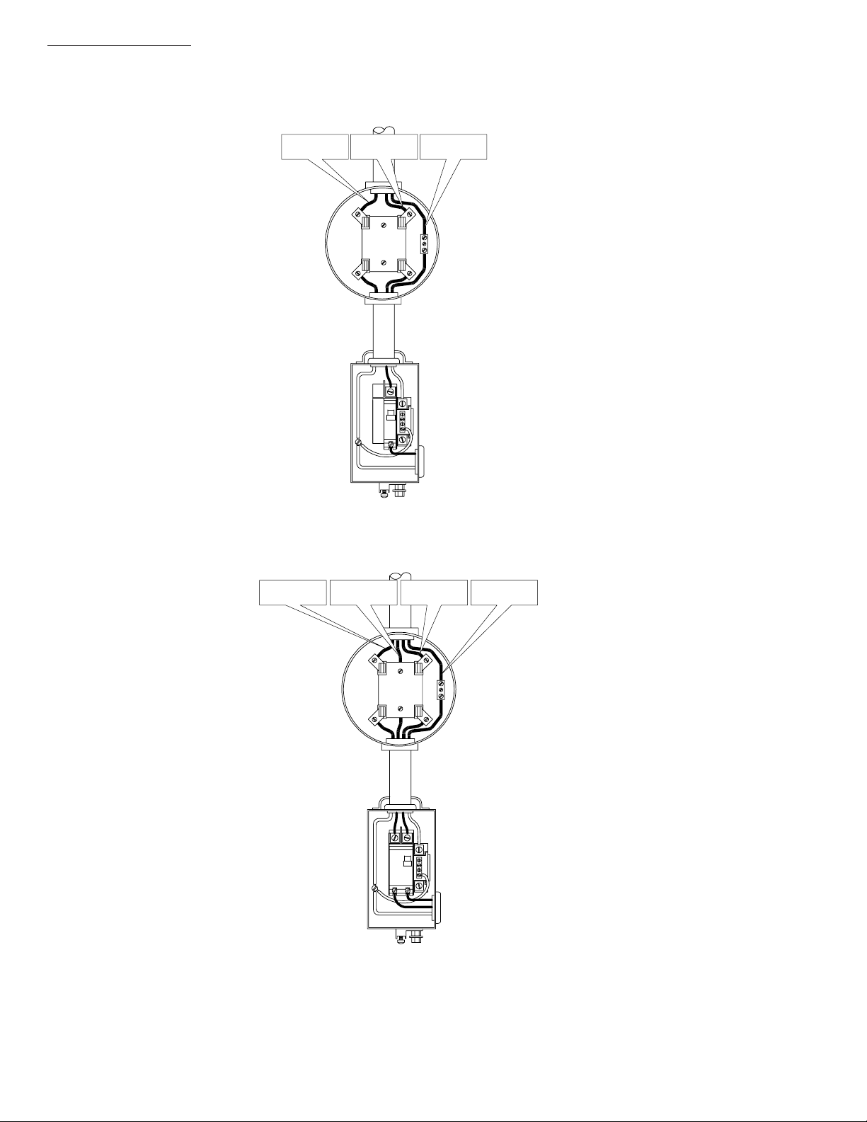
2.2 Utility Power Connection, continued
2. Installation
Ground
120 VAC
Service Entrance
From Utility
NeutralLine 1
ON
OFF
To EnclosureTo Ground Rod
240 VAC
Service Entrance
NeutralLine 1Line 2Ground From Utility
ON
OFFONOFF
To EnclosureTo Ground Rod
031-106-C1-001 Rev. A
Fig. 3 Service Entrance Wiring
13
Page 14
2. Installation
2.2 Utility Power Connection, continued
GroundNeutralline 1
ON
OFF
120 VAC Meter Base
ON
20
OFF
GroundLine 2Neutralline 1
240 VAC Meter Base
Fig. 4 Meter Base Wiring
14 031-106-C1-001 Rev. A
Page 15
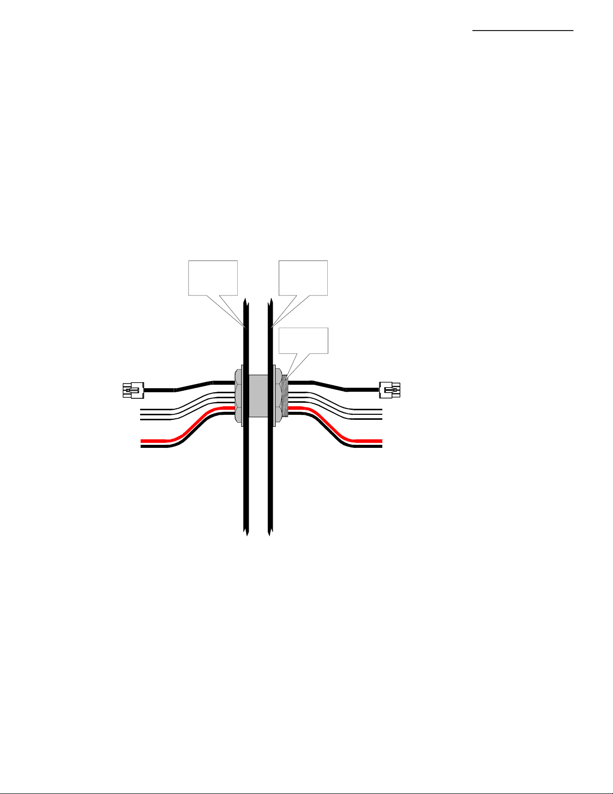
2.3 Generator / Sidecar Inter-connecting Cables
The following cables must be routed either through a 3" sweep or coupling:
#4 A WG DC Output from the generator
120 V AC power from the CESC sidecar service entrance
ECM or ACU Interface cable (status monitoring)
2. Installation
Sidecar
Enclosure
Back Wall
Generator
Enclosure
Side Wall
3" PVC
Coupling
ECM Interface (status monitoring)
Line
Neutral
120 VAC From Service Entrance
Ground
Positive
DC Output From Generator
Negative
031-106-C1-001 Rev . A
Fig. 5 Interconnection Wiring
15
Page 16

2. Installation
2.4 Internal Components
The Sidecar enclosure contains an Input Power Panel (IPP), one or two Service Power Inserters
(SPI),and the Enclosure Grounding Rail. The Power Supply rests on the upper shelf, and a
36 or 48 VDC battery pack on the lower two shelves.
A cooling fan is required any time a Power Supply is housed in the side car. The
fan is thermostatically controlled to turn on at ~140 deg F and off at ~110 deg
F. The fan cable has a 'T' connector that attaches to the Power Supply output
connection. Replace fuse only with a 1/4” X 1-1/4”, 5 Amp, 250 Volt
(Alpha P/N 460-025-10).
Thermostat
Cooling Fan
Input Power Pane l ( IP P)
AC Power
Connections
Fig. 6 Fan Connections
Fuse
Enclosure
Grounding Rail
Fig. 7
Location of IPP, SPI, and
Ground Rail
SPI
16 031-106-C1-001 Rev. A
Page 17

2.5 Battery Pack Wiring
2. Installation
4
3
1
2
48 Volt
Battery Pack
BCK P/N 874-665-20
Upper Shelf
3
1
Lower Sheff
2
36 Volt
Battery Pack
BCK P/N 874-664-20
031-106-C1-001 Rev . A
Fig. 8 36- & 48-Volt Battery String Wiring
17
Page 18
2. Installation
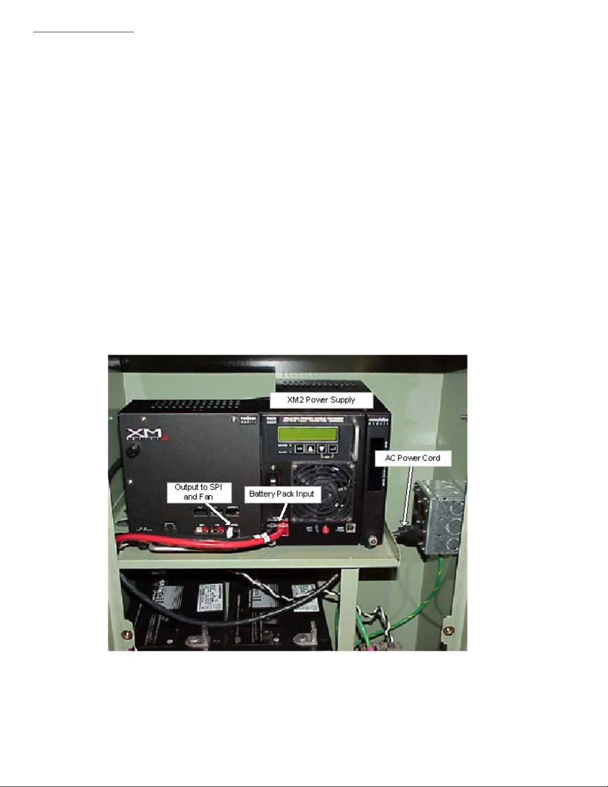
2.6 Power Supply Placement
1. Place the XM2 power supply onto the top shelf of the side car.
2. Verify that the AC Input Breaker in the service entrance is in the OFF position.
3. Verify that the Battery Breaker on the front of the power supply is in the OFF
position.
4. Plug the AC power cord into the Input Power Panel on the side of the enclosure.
5. Plug the Battery Input Cable from the battery pack into the Battery Input
connection on the front of the power supply .
6. Plug the wire leading from the fan into the OUTPUT 1 connection on the front of
the power supply .
7. Plug the wire leading from the top SPI into the other set of plugs on the wire
from the fan.
8. If a second SPI is installed, plug it into the OUTPUT 2 connection on the front of
the power supply .
Fig. 9 Power supply on Shelf
18 031-106-C1-001 Rev. A
Page 19

2.7 Battery Remote Temperature Sensor (RTS)
Tools Needed:
Adhesive T ape
Procedure:
For enclosures with multiple battery strings, the RTS must be located
with the WARMEST battery string. This ensures proper operation of
the battery charger’s temperature compensation circuit. Failure to
locate the RTS with the warmest battery string could result in
overcharging and premature battery failure. In this application, the RTS
MUST be attached to a battery in the upper tray of the side-car .
1. Attach the RTS Probe to the inner side of one of the batteries
on the upper tray of the side-car with adhesive tape.
2. The other side of the RTS Probe is attached to the front panel of the
XM2 power supply , in the jack labeled TEMP PROBE
2. Installation
031-106-C1-001 Rev . A
Fig. 10 Location of Temperature Sensor
19
Page 20

2. Installation
2.8 Service Power Inserter
1. The SPI box(es) are mounted on the shelf
support bracket.
2. Remove the two screws on the face of the
SPI and lift off the cover to gain access to
the Seizure Screw Assembly. Loosen the
seizure Screw several turns so that the
stinger will pass through the clamp. (Fig 2-3)
3, Insert the Coaxial T ermination into the output
port on the bottom of the SPI. Ensure that
the stinger goes through the Seizure Screw
Assembly. Tighten the Coaxial T ermination.
4. Tighten the seizure screw to 35.0 Inch-Pounds.
Replace the SPI cover and screws.
Ensure that the switch on the top or the SPI is
in the ON position, the AUX position is used
only when an alternate power source is
connected to the SPI.
Fig. 13 Location of SPI
Seizure Screw
Assembly
Seizure
Screw
Coax
Stinger
Coax
Termination
Fig. 1 1 Seizure Screw Assembly Location
Fig. 12 Cable Connection
20 031-106-C1-001 Rev. A
Page 21

Page 22

Page 23

Alpha Technologies
Power
®
Alpha T echnologies
3767 Alpha Way
Bellingham, WA 98226
USA
Tel: (360) 647-2360
Fax: (360) 671-4936
Web: www.alpha.com
Alpha Technologies Ltd.
4084 McConnell Court
Burnaby, BC, V5A 3N7
CANADA
Tel: (604) 430-1476
Fax: (604) 430-8908
Alpha T echnologies
Europe Ltd.
Cartel Business Estate
Edinburgh Way
Harlow, Essex CM20 2TT
UNITED KINGDOM
T el: +44-1279-422110
Fax: +44-1279-423355
Alpha T echnologies
Hansastrasse 8
D-91126 Schwabach
GERMANY
T el: +49-9122-79889-0
Fax: +49-9122-79889-21
Alphatec
339 St. Andrews Street
Suite 101
Andrea Chambers
Limassol, Cyprus
CYPRUS
T el: +357-25-375675
Fax: +357-25-359595
Alpha T echnologies
Unit R5-R7 Regents Park Estate
Corner Park Rd and Prince’s Rd
East
Regents Park, NSW 2143
AUSTRALIA
T el: +61-2-9722-3320
Fax: +61-2-9722-3321
Copyright © 2004 by Alpha Technologies, Inc. All rights reserved. Alpha is a registered trademark of Alpha Technologies. 031-106-C1-001 Rev. A.
Due to continuing product improvements, Alpha reserves the right to change specifications without notice.
 Loading...