

Page 1

CE-G Series
Propane Enclosures
CE-3G / CE-9G
Installation Manual
031-093-C0-001 © 3/99
Page 2

031-093-C0-001 © 3/99
Page 3

CE-G Series Enclosure
Installation Manual
Preface
Topic page
Overview i
About this Manual i
Table of Contents ii
List of Figures iii
Safety Information iv
Installation Notes v
Battery Safety Notes vi
Preface
Overview: The purpose of the CE-G Enclosure Installation Manual is to
provide an overview of the system and to detail the
enclosure installation procedure.
Audience: This manual intended for the installers and operators of the
system.
Contents: Section 1, System Overview. This section describes the
CE-G Series Enclosure.
Section 2, Pre-Installation. This section describes
site selection and pad layout.
Section 3, Installation. This section describes the
procedures for installing the cabinet.
Section 4, Operation. This section describes the preparation of
the cabinet for initial turn-up and the conversion of the APU fuel
source from Natural Gas to Propane.
i
031-093-C0-001 © 3/99
Page 4

Preface
CE-G Series Enclosure
Installation Manual
Table of Contents
Section 1, System Overview
1.1 Overview .................................................................................. 1-1
1.2 Block Diagram............................................................................... 1-2
Section 2, Pre-Installation
2.1 Site Preparation............................................................................ 2-1
2.1.1 Site considerations.............................................................. 2-1
2.1.2 Concrete pad layout ............................................................ 2-2
2.1.3 Enclosure impact protection ................................................. 2-3
Section 3, Installation
3.1 Tools and materials ....................................................................... 3-1
ii
3.2 Transportation.............................................................................. 3-2
3.3 Installation procedure .................................................................... 3-3
3.4 Enclosure impact protection ........................................................... 3-6
Section 4, Operation
4.1 Installation of tanks ...................................................................... 4-1
4.2 Installation of Regulator assembly ................................................... 4-2
4.3 Installation of HP/LP hoses ............................................................. 4-4
4.4 Converting the APU From Natural Gas To Propane Gas ........................ 4-5
4.4.1 Accessing the APU .............................................................. 4-5
4.4.2 Dual Fuel Load block conversion procedure ............................. 4-9
4.4.3 Conversion completion ....................................................... 4-10
4.5 Natural Gas To LP Gas conversion .................................................. 4-11
4.5.1 Pre-Regulator / Low Fuel-pressure switch conversion ............. 4-11
4.6 Remotely located CE-G enclosures................................................ 4-14
4.7 Converting Collocated enclosure for remote application ..................... 4-15
031-093-C0-001 © 3/99
Page 5

List of Figures
Section 1, Introduction
Figure 1.1 Colocated CE-X, CE-G enclosures .................................... 1-1
Figure 1.2 System Block Diagram .................................................... 1-2
Section 2, Pre-Installation
Figure 2.1 Concrete Pad Layout ..................................................... 2-2
Figure 2.2 Impact post arrangement .............................................. 2-3
Section 3, Installation
Figure 3.1 Gas Utility Box cutout .................................................... 3-3
Figure 3.2 Impact post arrangement ............................................... 3-6
Preface
Section 4, Operation
Figure 4.1 Tank base locator tabs ................................................... 4-1
Figure 4.2 Vapor outlet orientation .................................................. 4-1
Figure 4.3 Stop nut ............................................................ 4-2
Figure 4.4 Regulator assembly ........................................................ 4-2
Figure 4.5 Tank securing bracket .................................................... 4-3
Figure 4.6 High Pressure Hose arrangement ...................................... 4-4
Figure 4.7 Low Pressure Hose connection ........................................ 4-4
Figure 4.8 Exhaust pipe access panel .............................................. 4-5
Figure 4.9 Exhaust pipe flange bolts ................................................ 4-6
Figure 4.10 Fuel hose fitting ............................................................ 4-6
Figure 4.11 APU housing connectors ................................................. 4-7
Figure 4.12 APU tray locking bolts .................................................... 4-7
Figure 4.13 APU tray ............................................................ 4-8
Figure 4.14 Dual fuel load block ........................................................ 4-9
Figure 4.15 Exhaust pipe flange gasket ............................................. 4-10
Figure 4.16 Fuel hose placement, APU............................................... 4-10
Figure 4.17 Nat Gas pre-regulator removal ......................................... 4-11
Figure 4.18 Low fuel pressure switch wire placement........................... 4-12
Figure 4.19 Low fuel pressure switch placement ................................. 4-12
Figure 4.20 Low fuel pressure switch connector ................................. 4-13
Figure 4.21 Remote CE-G arrangemant .............................................. 4-14
Figure 4.22 Bolt hole locations ......................................................... 4-15
Figure 4.23 Remote gas utility box mounting location........................... 4-15
Figure 4.24 Hose connection ........................................................... 4-16
iii
031-093-C0-001 © 3/99
Page 6
Preface
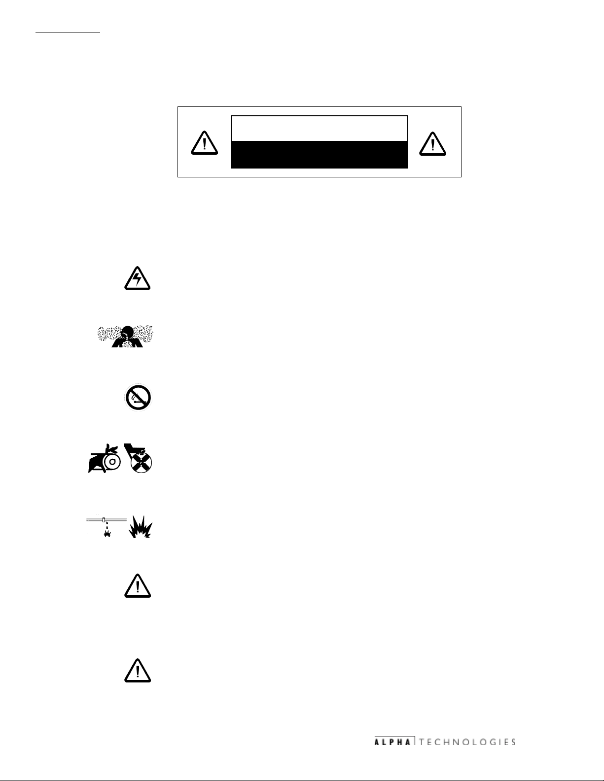
IMPORTANT SAFETY INSTRUCTIONS
CONTAINED IN THIS MANUAL
CAUTION
HAZARDOUS CONDITION
To reduce the risk of electrical shock, injury or death caused by explosion of
fuel or moving parts, and to ensure the safe operation of this unit, the following symbols have been placed throughout the manual. Where these symbols
appear, servicing should be performed only by qualified personnel.
DANGEROUS VOLTAGE
This symbol indicates a dangerous voltage exists in this area of the
product. Use caution whenever working in the area to prevent
electrical shock.
iv
INHALATION HAZARD - DONT BREATHE VAPORS
This symbol indicates an inhalation hazard exists in this area of the
product. Use caution whenever working in the area to prevent possible
inhalation of harmful (fuel or exhaust) vapors.
NO MATCHES OR OPEN FLAMES
This symbol indicates a fire or explosive hazard exists in this area of
the product. Use caution whenever working in the area to prevent
possible combustion fuel vapors.
MECHANICAL OR MOVING PARTS HAZARD
These symbols indicate the presence of a mechanical or moving parts
hazard in this area of the product. Use caution whenever working in
the area to prevent possible injury to the operator or servicepersonnel.
LEAK HAZARD
This symbol indicates a leak hazard exists in this area of the product.
Use caution whenever working in the area to prevent and correct any
leaks detected.
ATTENTION
This symbol indicates important installation, operation or maintenance
instructions. Always follow these instructions closely.
SAVE THESE INSTRUCTIONS
NOTE:
continual improvement processes. Therefore, specifications and/or
design layouts may vary slightly from descriptions included in this
manual. Updates to the manual will be issued when changes affect
form, fit or function.
031-093-C0-001 © 3/99
Alpha Technologies products are subject to change through
Page 7

IMPORTANT INSTALLATION NOTES
It is important that the installation procedures be followed as outlined in this
manual. The procedures have been developed to facilitate the installation of
the equipment and for the safety of the installation and service personnel.
Read the documentation thoroughly before proceeding with the installation.
The system should be installed ONLY by qualified service personnel.
Consult local utility codes for additional cabinet grounding and utility
requirements.
ALPHA TECHNOLOGIES is not responsible for broken welds of other damage to
the cabinet caused by improper installation.
All dimensions are given in inches.
For further information regarding this installation, contact ALPHA
TECHNOLOGIES or your nearest ALPHA representative.
Preface
v
031-093-C0-001 © 3/99
Page 8

Preface
Propane Safety Notes
1. Never overfill your LP-gas container. LPgas containers not
containing a fixed liquid level gauge must be filled by
weight to 80% of their total capacity. Propane expands
1.5% for each 10 °F increase in temperature. 20% of the
container must remain available for expansion. Some tanks
supplied by Alpha Technologies come equipped with automatic stop fill valves. Tanks must be filled in accordance
with manufactures, D.O.T, NFPA Code 58, state and local
regulations.
2. Do not use pliers to close the POL valve on your tank.
These valves are designed to be closed leak tight by hand or
screwdriver as appropriate. If pliers are needed to stop a
vi
leak , the valve needs replacement.
3. When tightening the POL Nut (left-hand thread) on the
service valve, draw it up snug with a proper wrench do not
jam it. No thread sealant is necessary. Check for leaks
after connecting, by using a leak detection solution or soapy
water.
4. If you take your LP-gas tank to a LP-gas dealer for filling,
transport it in the proper position in which it is used (vertical for all Alpha Technologies supplied tanks), with the
valves closed and the POL plug inserted. Secure the tank
against falling or rolling.
5. The outside of the tank should be kept corrosion free by
periodic checks and a coat of paint should be used if needed
(light reflective color).
031-093-C0-001 © 3/99
Page 9

Propane Safety Notes
6. Do not store LP-gas tanks indoors or in enclosed areas. Do
not expose the tanks to heat, relief valve may open. Always store with the service valve closed tight and plugged.
7. Do not attempt to repair LP-gas containers or valves or
regulators.
8. When using make sure that the tank is level, securely fastened down, and vertical.
9. Check all tank and line connections periodically to be sure
they are tight. When testing for leaks use soapy water or a
leak detect solution. Do not use any open flame for leak
testing.
Preface
vii
031-093-C0-001 © 3/99
Page 10

Preface
viii
031-093-C0-001 © 3/99
Page 11
1. System Overview
1.1 Overview
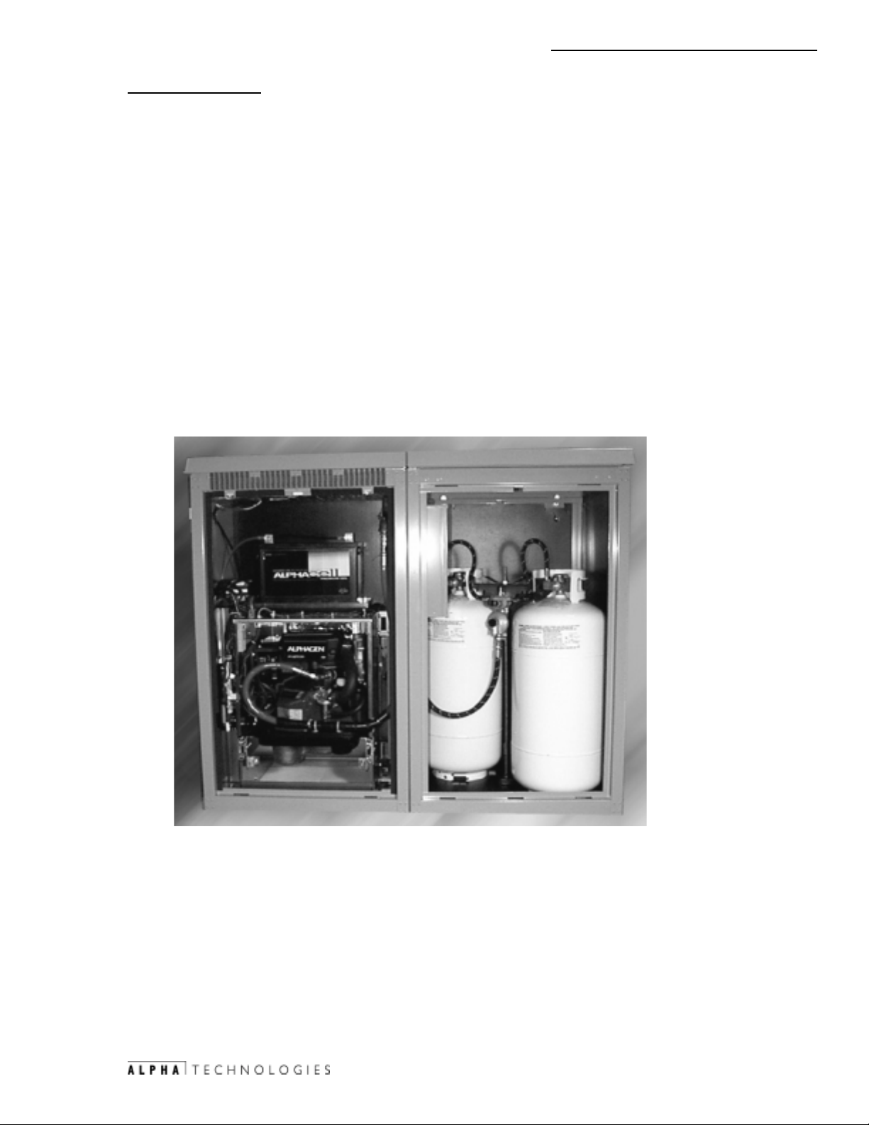
The CE-X series of enclosures from Alpha Technologies has been
designed to meet the needs of todays outside plant powering requirements.
When an alternate fuel source is not available, the CEG propane natural gas
option can provide up to 16 hours of continuous operation.
The procedures described in this document describe the installation of a
CE-G Series Propane Enclosure. The installation procedures are identical for
the CE-3G and the CE-9G. The cabinet footprint (and mounting hole location)
is identical for each enclosure. The only physical difference between the
enclosures is that the CE-3G is 44 tall and the CE-9G is 52 tall.
Fig.1.1, Collocated CE-X/CE-G enclosures
1-1
031-093-C0-001 © 3/99
Page 12
1. System Overview
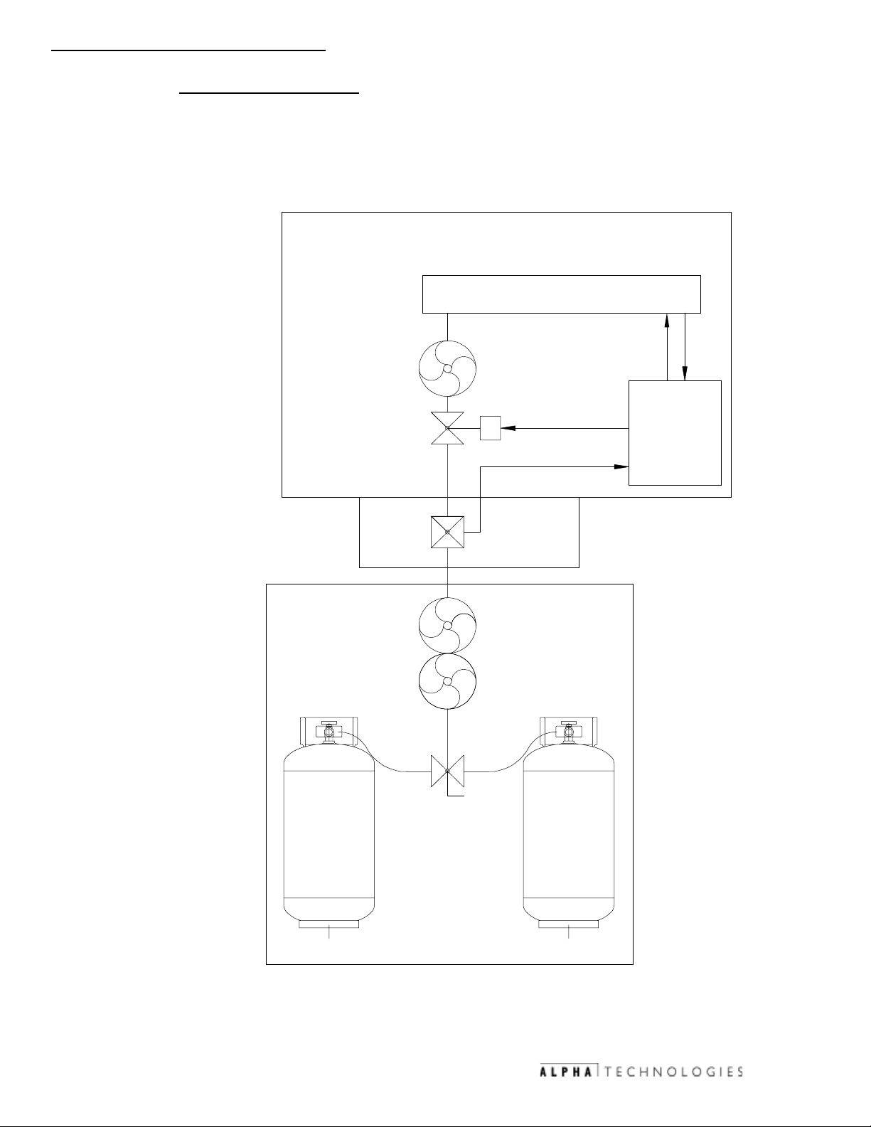
1.2 Block Diagram
The block diagram shown illustrates the overall system interconnection
between the CE-X enclosure with Auxiliary Power Unit, and the CE-G enclosure
with supplemental propane supply.
LOW PRESSURE
ENCLOSURE
LP PROPANE - VAPOR WITHDRAWAL
BLOCK DIAGRAM
ENGINE
DEMAND
CONTROLS
REGULATOR
8oz
APU
MAX
S
11"WC
SOLENOID
CONTROL
LOW FUEL ALM
1-2
SENSOR
11"WC
OUTLET
PROPANE 150 PSI
HIGH PRESSURE
PRE-REGULATOR
AUTO/MANUAL
PROPANE
PROPANE
10 PSI TO 11"WC
DUAL TANK
VALVE
LOW FUEL
PRESSURE
SWITCH
POST-REG
PROPANE
ENCLOSURE
PROPANE
GAS
UTILITY
BOX
031-093-C0-001 © 3/99
Fig. 1.2, System block diagram
Page 13

1. System Overview
this page intentionally Blank
1-3
031-093-C0-001 © 3/99
Page 14

1. System Overview
1-4
this page intentionally Blank
031-093-C0-001 © 3/99
Page 15

2. Pre-Installation
2.1 Site Preparation
2.1.1 Site considerations
The site for the collocated CE-G will be predetermined by
the location of the CE-X enclosure.
The site for the remotely located CE-G should be planned so
that the enclosure will receive good air flow. If possible, in areas
of extreme heat, the enclosure should be positioned so that it
will be shaded from the afternoon sun. In areas of prevailing
winds, the enclosure should be located so that the side of the
cabinet face into the direction of the prevailing wind. This will
greatly reduce the amount of wind borne matter (dirt, snow, and
debris) which may enter the enclosure through the louvers or
vents.
In areas of flooding, the geographical site and concrete pad
should be located above the flood plane.
Place the front of the enclosure facing the street, where
component access will be curbside. In most instances,
landscaping such trees, shrubs, or wooden fences serve to
provide a more acceptable appearance in keeping with
surrounding neighborhood designs.
The enclosure should be placed where it will be free of
obstructions.
2-1
031-093-C0-001 © 3/99
Page 16

2. Pre-Installation
2.1 Site Preparation, continued
The illustration below shows the general dimensions for a poured
in place concrete pad. When placing the pad, allow at least 36
inches of clearance to allow the front and rear doors to fully
open.
2.1.2 Concrete Pad Layout
2-2
1
2
1
Fig.2-1, Concrete pad layout (all dimensions shown in inches)
1
1
031-093-C0-001 © 3/99
1
3/8" diameter (4 places) bolts (which should extend
1"-1 1/2" above the surface of the pad). All mounting hardware
must be stainless steel to prevent corrosion.
A 25+ year continuous vapor barrier must be used between the
2
enclosure and pad to prevent moisture ingress and corrosion
caused by metal-to-concrete contact. The vapor barrier material
(such as 30 lb. felt, neoprene pond liner, or heavy grade tar
paper) should initially extend at least 6" in all directions around
the perimeter of the enclosure. After the enclosure is in place, the
material should be cut closer to the enclosure, using the
appropriate knife or cutting tool.
Page 17

2. Pre-Installation
2.1 Site Preparation, continued
2.1.3 Enclosure Impact Protection
As described in the NFPA Technical Compliance Statement,
the cabinet must be protected by impact posts, placed in
strategic locations according to traffic patterns. The illustration
below shows the general arrangement of the 6 diameter,
concrete-filled posts. The actual positioning of the posts may
vary by location.
FRONT
TRAFFIC
TRAFFIC
PROPANEAPU
POSTS
CURB
CE-X CE-G
PAD
Fig.2-2, Impact post arrangement (typical)
SIDEWALKSIDEWALK
2-3
STREET
031-093-C0-001 © 3/99
Page 18

2. Pre-Installation
2-4
this page intentionally Blank
031-093-C0-001 © 3/99
Page 19

3. Installation
3.1 Tools and Materials
The following procedure will allow for installation of the Collocated CE-G with
the CE-X/ CE-X2. The CE-G enclosure re is bolted to the concrete pad using
7/16 bolts and to the CE-X APU enclosure by carriage bolts. Also this
procedure will explain step by step how to install the two 40 LB propane tanks
and the regulator /control valve.
Tools:
(2) Pipe wrench 10
7/8 combination box and open ended wrench
Straight slot screw driver
Multimeter
Adjustable crescent wrench 10
1/2 open ended wrench
Materials
QTY
(1) Regulator hold down bracket assembly
(2) 40 pound DOT approved propane tanks
(1) CE-G Enclosure
3-1
031-093-C0-001 © 3/99
Page 20

3. Installation
3.2 Transportation
transported, loaded, and unloaded while bolted to the shipping pallet. A safe
means of transportation to the site and unloading the enclosure must be
considered. Do not transport, lift, or place the unit on any surface unable to
fully support its weight.
The enclosure is shipped bolted to a shipping pallet. It should be
3-2
NOTE:
The enclosure should only be transported, lifted, and
installed as shipped from the factory. Do not install the
propane tanks until the enclosure is installed on the pad.
031-093-C0-001 © 3/99
Page 21

3. Installation
3.3 Installation Procedure
1. Install the CE-G enclosure so that the gas utility box of the CE-X
enclosure fits into the gas utility box cutout on the CE-G (dashed line) as
pictured below. Ensure the two cabinets are placed flush against each
other.
2. With the two cabinets sitting flush against each other, mark the anchor
bolt pattern onto the concrete pad using the four slotted anchor bolt
holes found in the corners of the base plate of the CE-G enclosure as an
template.
3. Also, mark the hole which will be used to bolt the cabinets together
(located at the lower left corner of the gas utility box cutout).
1
3
Fig. 3.1, Gas utility box cutout, connection bolt location
3-3
031-093-C0-001 © 3/99
Page 22

3. Installation
3.3 Installation Procedure, continued
3. Slide the CE-G enclosure away from the CE-X enclosure.
4. Drill with a 1/4 hole through the wall of the CE-X enclosure where
previously marked.
3-4
NOTE:
5. With the anchor bolt pattern marked, drill holes for the installation of
anchor studs.
Tools required:
Stainless steel wedge-type stud anchor , 3/8" dia., 3-3/4" in length (4).
4 each, 3/8 flat washer, 3/8 lock washer, and hex nut.
Hand Drill or Rotary Hammer
3/8 Concrete or Masonry bit(s)
Hammer
Mounting bolt installation procedure:
1. At the points located in step 3 above, drill holes for the anchor studs.
Each hole should be at least 1-3/4 deep to properly secure the
enclosure to the pad.
2. With the hammer, tap the anchor studs into their respective holes.
3. Brush away any debris from the drilling prior to proceeding.
Before drilling through the CE-X cabinet wall,
ensure that the area behind the wall is clear
of any wires, gas hoses, or pipes.
031-093-C0-001 © 3/99
Page 23

3. Installation
3.3 Installation Procedure, continued
5. Lay down the vapor barrier material. With a utility knife, make small
cutouts in the material through which the anchor studs protrude.
6. Place the CE-G enclosure back into place over the mounting studs.
7. With CE-G enclosure in place and flush against the CE-X enclosure,
install the mounting hardware (flat washers, lock washers, and 3/8
nuts) on each mounting bolt. Do not tighten at this time.
8. Install the 1 x 1/4 x 20 bolt through the lower left side bolt hole of the
gas utility box cutout (drilled in Step 4). Secure the bolt using a lock
washer, flat washer and nut.
9. Once the two cabinets have been secured together, evenly tighten the
anchor stud mounting hardware.
NOTE:
ALPHA TECHNOLOGIES is not responsible for
broken welds of other damage to the cabinet
caused by improper installation.
3-5
031-093-C0-001 © 3/99
Page 24

3. Installation
3.4 Enclosure Impact Protection
As described in the NFPA Technical Compliance Statement, the cabinet must
be protected by impact posts, placed in strategic location according to traffic
patterns.
3-6
FRONT
TRAFFIC
TRAFFIC
PROPANEAPU
POSTS
SIDEWALKSIDEWALK
CURB
STREET
CE-X CE-G
PAD
Fig.3.2, Impact post arrangement (typical)
Once the impact posts (Concrete-filled, 6 diameter, steel) have been
placed, proceed to the next section for the Propane Tank Installation procedure.
031-093-C0-001 © 3/99
Page 25

3. Installation
this page intentionally Blank
3-7
031-093-C0-001 © 3/99
Page 26

4. Operation
4.1 Installation of the propane tanks and regulator assembly
4.1.1 Installation of tanks
1. Place the rear tank into the enclosure through the rear access and the
front tank through the front access. Ensure that the base of each tank
fits into the tabs of the base plate, as shown below.
Figure 4.1, Tank base locator tabs
2. The tanks' vapor outlets should be facing towards the gas utility box (the
front left of the enclosure).
4-1
Figure 4.2, Vapor outlet orientation
031-093-C0-001 © 3/99
Page 27

4. Operation
4.2 Installation of Regulator Assembly
1. On tank hold down rod adjust stop nut so that the tank hold down
bracket aligns with the bottom edge of the tank valve guard / handle, as
shown below.
4-2
Figure 4.3, Stopnut
2. Slide regulator / hold down bracket assembly onto the hold down rod.
Ensure regulator assembly is facing same direction of tank valve vapor
ports, and that the hold down brackets outermost grooves fits onto the
bottom edge of the valve guard.
031-093-C0-001 © 3/99
Figure 4.4, Regulator assembly
Page 28

4.2 Installation of Regulator Assembly, continued
3. Install the hold down bracket wing nut onto the hold down rod and
tighten down.
4. Operation
Figure 4.5, Tank securing bracket
4-3
031-093-C0-001 © 3/99
Page 29

4. Operation
4.3 Installation of High Pressure and Low Pressure Hoses
4.3.1 Installation of high pressure Hoses
1. Install high pressure hoses into the tanks vapor outlet port with a
service loop pointing upward, as shown below.
4-4
Figure 4.6, High-pressure hose arrangement
4.3.2Installation of high pressure Hoses
1. Install the Low pressure hose onto the Low fuel pressure switch,
located in the gas utility box, as shown below.
031-093-C0-001 © 3/99
Figure 4.7, Low-pressure hose connection
Page 30

4. Operation
4.4 Converting APU From Natural Gas To Propane Gas
4.4.1 Accessing the APU
1. Remove rear cabinet door.
2. Remove the exhaust pipe access panel, by removing the 6 panel screws.
Remove panel screws
Figure 4.8, Exhaust pipe access panel
4-5
031-093-C0-001 © 3/99
Page 31

4. Operation
4.4 Converting APU From Natural Gas To Propane Gas, cont.
4.4.1 Accessing the APU, continued
3. Use a 10mm socket and ratchet remove the two flange bolts
that connect the flex exhaust pipe to the upper exhaust pipe.
4-6
Figure 4.9, Exhaust pipe flange bolts
4. Disconnect fuel hose at the APU 45° fitting. Cut cable ties from hose.
031-093-C0-001 © 3/99
Figure 4.10, Fuel hose fitting
Page 32

4. Operation
4.4 Converting APU From Natural Gas To Propane Gas, cont.
4.4.1 Accessing the APU, continued
5. Disconnect the APU connector, Battery Connector, Fuel Solenoid and ACU
12 pin connector from the top panel of thegenerator enclosure.
Figure 4.11,APU housing connetors
6. Use a 9/16" socket remove the two slide retaining bolts. (picture)
4-7
Figure 4.12, APU tray locking bolts
031-093-C0-001 © 3/99
Page 33

4. Operation
4.4 Converting APU From Natural Gas To Propane Gas, cont.
4.4.1 Accessing the APU, continued
7. Slide the APU out.
4-8
Figure 4.13, APU in tray
031-093-C0-001 © 3/99
Page 34

4. Operation
4.4 Converting APU From Natural Gas To Propane Gas, cont.
8. Dual Fuel Load Block conversion from Natural Gas to Liquid Propane Gas.
Procedure:
1. Remove the blanking plug from the lower outlet port on the load
block.
2. Loosen the hose clamp on the fuel supply hose at the load block.
3. Loosen the brass fitting and remove from the upper outlet port (NG
port) and install in the lower outlet port (LP port).
4. Retighten the hose clamp.
5. Install the blanking plug into the upper outlet port.
NOTE
1
: Apply a high-quality gas pipe thread sealant to the
blanking plug and brass fitting threads.
4-9
3
2,4
5
Figure 4.14,Dual fuel load block
031-093-C0-001 © 3/99
Page 35

4. Operation
4.4 Converting APU From Natural Gas To Propane Gas, cont.
9. Reconnect the APU exhaust and Fuel Hose
Procedure:
1. Install new gasket at the exhaust Flex pipe flange.
2. Apply antiseize compound to the flange bolts and install into flange
3. Torque the exhaust pipe flange bolts, bolt to bolt, to 7-ft/pounds.
4-10
Figure 4.15, Exhaust pipe flange gasket
4. Reconnect the fuel hose with cable ties to the proper anchor points (see
below). Verify the chafe guard is properly seated in the cut out before the
APU drawer is closed.
5. Once the fuel hose is securely fastened, slide the APU drawer back in the
enclosure and re-fasten the retaining bolts.
NOTE:
Verify fuel hose
is completely
wrapped in
chafe guard
material and
fully seated in
cutout.
031-093-C0-001 © 3/99
Figure 4.16, Fuel hose placement, APU
Page 36

4. Operation
4.5 Pre-Regulator/Low-Fuel Pressure Package Conversion
4.5.1 Converting from Natural Gas Pre-regulator Gas Package to LP Gas
Low fuel Pressure switch
Removal Procedure:
1. Have authorized personnel disconnect the Natural Gas at the manual
shutoff valve.
2. De-couple the input piping at a point outside of the gas utility box.
3. In the Gas Utility Box locate the Pre-regulator, disconnect at the coupler
fitting. (see picture)
4. Lift pre-regulator up and out of the gas utility box.
Figure 4.17,Natural Gas pre-regulator removal
4-11
031-093-C0-001 © 3/99
Page 37

4. Operation
4.5 Pre-Regulator/Low-Fuel Pressure Package Conversion, cont.
LP Gas low fuel pressure switch Installation procedure
1. Route the low fuel pressure switch wires (connector not installed)
located on the back wall of the gas utility box.
4-12
Figure 4.18, Low fuel pressure switch wire placement
2. Install the Low fuel pressure Switch package on to the gas inlet elbow
fitting.
NOTE:
The switch package is joined to the input pipe with a
compression fitting. DO NOT overtighten this fitting,
as that will cause it not to be leak tight.
031-093-C0-001 © 3/99
Figure 4.19, Low fuel pressure switch placement
Page 38

4. Operation
4.5 Pre-Regulator/Low-Fuel Pressure Package Conversion, cont.
LP Gas low fuel pressure switch Installation procedure
3. Install the two position connector onto the low fuel pressure switch wire
harness, Black wire to Pin 1, White to Pin 2.
4. Connect the switch side wire harness connector to the cabinet side low
fuel pressure switch connector.
Figure 4.20,Low fuel pressure switch connector
4-13
031-093-C0-001 © 3/99
Page 39

4. Operation
7. CEG Enclosures Used In Remote Applications
The collocated CEG enclosure can be converted to be a remotely located
enclosure at distances of no more than 25 feet from the APU. This remote
operation requires the use of interconnecting buried gas pipe, between the
APU cabinet and the CEG cabinet. All pipe and pipe fittings running from the
CEX to the CEG will be installed in accordance with local code. All materials
used must meet approval of all local codes.
4-14
CAUTION
3" SWEEP
: Due to the Low Pressure Output of the CEG,
(1"), all interconnecting gas pipe must be 1"
to 3/4" inch diameter to ensure proper flow.
GAS
DWYER LOW
FUEL SENSOR
MANUAL SHUTOFF
REQUIRED IF CE-G
CANNOT BE SEEN
PROPANE VAPOR
031-093-C0-001 © 3/99
Figure 4.21, Remote CE-G arrangement
Page 40

4. Operation
7.1 Converting Collocated CEG Enclosure For Remote Application
1. Locate the gas utility box cut out on the left wall of CEG.
2. Align the Remote Gas Utility Box Assembly with the pre drilled bolt holes
surrounding the cut out.
2
Figure 4.22, Bolt hole locations
3. Use the six carriage bolts and supplied hardware, to mount the remote gas
utility box to the outside of the CE-G enclosure wall.
4-15
Figure 4.23,Remote gas utility box mounting location
031-093-C0-001 © 3/99
Page 41

4. Operation
7.1 Converting Collocated CEG Enclosure For Remote Application
3. Install the gas hoses to the brass fitting located on the inside of remote
gas utility box. (see picture)
4. Hook up interconnecting gas pipe to the remote utility gas box pipe
fixture.
4-16
Figure 4.24,Hose connection
End of conversion Procedure
1. Securely fasten all hoses.
2. Open previously-filled gas bottles.
3. Perform leak check with approved leak-detection solution
031-093-C0-001 © 3/99
Page 42

4. Operation
this page intentionally blank
4-17
031-093-C0-001 © 3/99
Page 43

031-093-C0-001 © 3/99
Page 44
Investigate the
of Alpha @www.alpha.com
UNITED STATES
ASIA PACIFIC
LATIN AMERICA
Alpha Technologies
3767 Alpha Way
Bellingham, WA 98226
Tel: (360) 647-2360
Fax: (360) 671-4936
Web: www.alpha.com
CANADA
Alpha Technologies
7033 Antrim Ave.
Burnaby, B.C. V5J 4M5
Tel: (604) 430-1476
Fax: (604) 430-8908
UNITED KINGDOM
Alpha Technologies
Cartel Business Estate
Edinburgh Way
Harlow, Essex CM20 2DU
Tel: +44-1279-422110
Fax: +44-1279-423355
Due to continuing product
improvements, Alpha reserves
the right to change
specifications without notice.
©1999
Alpha Technologies Inc.
All rights reserved.
031-093-C0-001 © 3/99
GERMANY
Alpha Technologies
Hansastrasse 8
D-91126 Schwabach
Tel: +49-9122-997303
Fax: +49-9122-997321
MIDDLE EAST
Alphatec
P.O. Box 6468
3307 Limassol, Cyprus
Tel: +357-5-375675
Fax: +357-5-359595
AUSTRALIA
Alpha Technologies
8 Anella Ave., Unit 6
Castle Hill, NSW 2154
Tel: +61 (0)2 9894-7866
Fax: +61 (0)2 9894-0234
 Loading...