

Page 1
CE3G Enclosure
CE3G Enclosure
Fuel Quantity Alarm
Installation and Operation Manual
Effective: June, 2005
Alpha Technologies
®
Page 2

Alpha Technologies
Power
Page 3

Fuel Quantity Alarm Option
745-738-C0-001, Rev A
Effective Date: June, 2005
Copyright© 2005
Alpha Technologies, Inc.
A member of The Alpha Group
NOTE
Photographs contained in this manual are for illustrative purposes only. These photographs may not match
your installation.
NOTE
Operator is cautioned to review the drawings and illustrations contained in this manual before proceeding. If
there are questions regarding the safe operation of this product, please contact Alpha Technologies or your
nearest Alpha representative.
NOTE
Alpha shall not be held liable for any damage or injury involving its enclosures, power supplies, generators,
batteries, or other hardware if used or operated in any manner or subject to any condition not consistent with
its intended purpose, or is installed or operated in an unapproved manner, or improperly maintained.
Contacting Alpha Technologies: www.alpha.com
OR
For general product information and customer service (7 AM to 5 PM, Pacifi c Time), call
1-800-863-3930
For complete technical support, call
1-800-863-3364
7 AM to 5 PM, Pacifi c Time or 24/7 emergency support
3745-738-C0-001 Rev. A
Page 4

Table of Contents
Safety Notes, Guidelines, and Precautions ........................................................................... 6
General Safety Precautions................................................................................................... 7
Battery Safety Notes.............................................................................................................. 8
Chemical Hazards ................................................................................................................. 8
Electrical Safety ..................................................................................................................... 9
Gas Safety ............................................................................................................................. 9
Battery Maintenance Guidelines.......................................................................................... 10
Recycling and Disposal ....................................................................................................... 10
Auxiliary Power Unit (APU) Notes ....................................................................................... 10
1.0 Introduction ................................................................................................................11
1.1 Pre-Installation ................................................................................................11
1.1.1 Parts, Tools, and Checklist ...................................................................11
1.2 Installation ...................................................................................................... 12
1.2.1 Installing Alarm Housing...................................................................... 12
1.2.2 Removing Low Fuel Pressure Switch Connector ................................ 13
1.2.3 Gas Box Modifi cation .......................................................................... 14
1.2.4 Cable Connection and Routing ........................................................... 15
1.2.5 Sensor Module Installation .................................................................. 17
1.2.6 Reinstall Ignition Battery ..................................................................... 18
1.3 Alarm Operation ............................................................................................. 19
1.4 Return Unit to Service .................................................................................... 20
4
745-738-C0-001 Rev. A
Page 5

Figures and Tables
Fig. 1-1, Alarm Housing Fastener Location ....................................................... 12
Fig. 1-2, Alarm Housing Placement ...................................................................12
Fig. 1-3, Cable Connection and Routing............................................................12
Fig. 1-4 Low Fuel Pressure Switch (LFPS) Connector, Bulkhead Fitting ......... 13
Fig. 1-5 LFPS Connector Wiring .......................................................................13
Fig. 1-6 LFPS Assembly ...................................................................................14
Fig. 1-7 LFPS Wiring, Bulkhead Fitting.............................................................14
Fig. 1-8 Bottom View, Gas Utility Box ............................................................... 14
Fig. 1-9 Sensors and Nut ..................................................................................15
Fig. 1-10 Water-tight Bulkhead Fitting ................................................................ 15
Fig. 1-11 Sensor Modules and Water-tight Bulkhead Fitting .............................. 15
Fig. 1-12 Wiring Inside Gas Box ......................................................................... 16
Fig. 1-13 Reposition LFPS..................................................................................16
Fig. 1-14 Wire Arrangement, Generator Cabinet Side ........................................ 16
Fig. 1-15 Dust Cap Removal .............................................................................. 17
Fig. 1-16 Sensor Module Installation .................................................................. 17
Fig. 1-17 Completed Sensor Installation.............................................................17
Fig. 1-18 Completed Alarm Kit Installation.......................................................... 18
Fig. 1-19 Fuel Quantity Alarm Relay Wiring Harness .........................................19
Fig. 1-20 J2 Fuel Relay PCB Connections ......................................................... 20
5745-738-C0-001 Rev. A
Page 6

Safety Notes, Guidelines, and Precautions
Review the drawings and illustrations contained in this manual before proceeding. If there are any questions
regarding the safe installation or operation of the system, contact Alpha Technologies or the nearest Alpha
representative. Save this document for future reference.
To reduce the risk of injury or death, and to ensure the continued safe operation of this product, the following
symbols have been placed throughout this manual. Where these symbols appear, use extra care and
attention.
ATTENTION!
The use of ATTENTION indicates specifi c regulatory/code requirements that may affect the placement of
equipment and installation procedures.
NOTE
A NOTE provides additional information to help complete a specifi c task or procedure.
CAUTION!
The use of CAUTION indicates safety information intended to PREVENT DAMAGE to material or
equipment.
WARNING!
A WARNING presents safety information to PREVENT INJURY OR DEATH to the
technician or user.
6
745-738-C0-001 Rev. A
Page 7

General Safety Precautions
To avoid injury:
• This enclosure and its associated hardware must be serviced only by authorized personnel.
• Enclosure must remain locked at all times, except when authorized service personnel are present.
• Remove all conductive jewelry or personal equipment prior to servicing equipment, parts,
connectors, wiring, or batteries.
• Read and follow all installation, equipment grounding, usage, and service instructions included in this
manual.
• Use proper lifting techniques whenever handling enclosure, equipment, parts, or batteries.
• Batteries contain dangerous voltages, currents and corrosive material. Battery installation,
maintenance, service and replacement must be performed by authorized personnel only.
• Never use uninsulated tools or other conductive materials when installing, maintaining, servicing or
replacing batteries.
• Use special caution when connecting or adjusting battery cabling. An improperly connected battery cable
or an unconnected battery cable can result in arcing, a fi re, or possible explosion.
• A battery that shows signs of cracking, leaking or swelling must be replaced immediately by authorized
personnel using a battery of identical type and rating.
• Avoid any contact with gelled or liquid emissions from a valve-regulated lead-acid (VRLA) battery.
Emissions contain dilute sulfuric acid which is harmful to the skin and eyes. Emissions are electrolytic,
which are electrically conductive and are corrosive. Follow the Chemical Hazards notes if contact occurs.
• Do not smoke or introduce sparks in the vicinity of a battery.
• Under certain overcharging conditions, lead-acid batteries can vent a mixture of hydrogen gas that is
explosive. Proper venting of the enclosure is required.
CAUTION!
Enclosure, equipment or parts may be damaged or cause damage if used or installed improperly.
To avoid damage:
• Prior to installation, verify that the AC input voltage to the enclosure and its equipment match with respect
to voltage and frequency.
• Prior to installation, verify that the output voltage from the enclosure or its equipment match the voltage
requirements of the connected equipment (load).
• Prior to installation, verify that the enclosure’s utility service panel is equipped with a properly rated circuit
breaker for use with the equipment inside. Refer to manufacturer’s recommendations.
• Review and upgrade utility service panel circuit breaker requirements whenever the equipment within the
enclosure is changed.
• Prior to installation, contact local utilities, local building maintenance departments, and cable/piping
locator services to ensure that installation does not interfere with existing utility or building cables/piping.
• Do not exceed the output rating of equipment. Verify load requirements prior and during connection
process.
7745-738-C0-001 Rev. A
Page 8

Battery Safety Notes
WARNING!
Lead-acid batteries contain dangerous voltages, currents and corrosive material. Battery
installation, maintenance, service and replacement must be performed only by authorized
personnel.
Chemical Hazards
Any gelled or liquid emissions from a valve-regulated lead-acid (VRLA) battery contain dilute sulfuric
acid, which is harmful to the skin and eyes. Emissions are electrolytic, and are electrically conductive and
corrosive.
To avoid injury:
• Servicing and connection of batteries shall be performed by, or under the direct supervision of, personnel
knowledgeable of batteries and the required safety precautions.
• Always wear eye protection, rubber gloves, and a protective vest when working near batteries. Remove
all metallic objects from hands and neck.
• Batteries contain or emit chemicals known to the State of California to cause cancer and birth defects
or other reproductive harm. Battery post terminals and related accessories contain lead and lead
compounds. Wash hands after handling (California Proposition 65).
• Wear protective clothing (insulated gloves, eye protection, etc.) whenever installing, maintaining,
servicing, or replacing batteries.
• If any battery emission contacts the skin, wash immediately and thoroughly with water. Follow your
company’s approved chemical exposure procedures.
• Neutralize any spilled battery emission with the special solution contained in an approved spill kit or with
a solution of one pound Bicarbonate of soda to one gallon of water. Report chemical spill using your
company’s spill reporting structure and seek medical attention if necessary.
• Always replace batteries with those of an identical type and rating. Never install old or untested batteries.
• A battery showing signs of cracking, leaking, or swelling should be replaced immediately by Authorized
Personnel using a battery of identical type and rating.
8
745-738-C0-001 Rev. A
Page 9

Electrical Safety
• Lethal voltages are present within the power supply and electrical boxes. Never assume that an electrical
connection or conductor is not energized. Check the circuit with a volt meter with respect to the grounded
portion of the enclosure (both AC and DC) prior to any installation or removal procedure.
• Always use the buddy system when working under hazardous conditions.
• A licensed electrician is required to install permanently wired equipment.
• Input voltages can range up to 240 VAC. Ensure that utility power is disabled before beginning installation
or removal.
• Use tools with insulated handles, do not rest any tools on top of batteries.
• Ensure no liquids or wet clothes contact internal components.
• Hazardous electrically live parts inside this unit are energized from batteries even when the AC input
power is disconnected.
• Prior to handling the batteries, touch a grounded metal object to dissipate any static charge that may have
developed on your body.
• Never use uninsulated tools or other conductive materials when installing, maintaining, servicing or
replacing batteries.
• Use special caution when connecting or adjusting battery cabling. An improperly connected battery cable
or an unconnected battery cable can make contact with an unintended surface that can result in arcing,
fi re, or possible explosion.
Gas Safety
• Do not smoke or use any source of fl ame around gas lines. Propane and natural gas are extremely
fl ammable, and explosive at high concentrations. Large releases can create a fl ammable vapor cloud.
• Batteries produce explosive gases. Keep all open fl ames and sparks away from batteries.
• At high concentrations gas is an asphyxiant that displaces oxygen from the breathing atmosphere.
• Contact with liquid may cause skin and eye burns.
• Do not charge batteries in a sealed container. Each individual battery should have at least 0.5
inches of space between it and all surrounding surfaces to allow for convection cooling.
• All battery compartments must have adequate ventilation to prevent an accumulation of potentially
dangerous gas.
9745-738-C0-001 Rev. A
Page 10

Battery Maintenance Guidelines
The battery maintenance instructions listed below are for reference only. Battery manufacturer’s instructions
for transportation, installation, storage or maintenance take precedence over these instructions.
• To prevent damage, inspect batteries every 3 months for:
Signs of battery cracking, leaking or swelling. The battery should be replaced immediately by
authorized personnel using a battery of the identical type and rating.
Signs of battery cable damage. Battery cable should be replaced immediately by Authorized Personnel
using replacement parts specifi ed by vendor.
Loose battery connection hardware. Refer to battery manufacturer’s documentation for the correct
torque and connection hardware for the application.
• Apply battery manufacturer’s specifi ed antioxidant compound on all exposed connections.
• Verify battery terminals and/or exposed connection hardware is not within 2 inches of a conductive
surface. Reposition batteries as necessary to maintain adequate clearance.
• Clean up any electrolyte (battery emission) in accordance with all federal, state, and local regulations or
codes.
• Proper venting of the enclosure is recommended. Follow the Battery Manufacturer’s approved
transportation and storage instructions.
• Always replace batteries with those of an identical type and rating. Never install old or untested batteries.
• Do not charge batteries in a sealed container. Each individual battery should have at least 0.5
inches of space between it and all surrounding surfaces to allow for convection cooling.
• All battery compartments must have adequate ventilation to prevent an accumulation of potentially
dangerous gas.
Recycling and Disposal
Spent or damaged batteries are considered environmentally unsafe. Always recycle used batteries or dispose
of the batteries in accordance with all federal, state and local regulations.
Auxiliary Power Unit (APU) Notes
When the engine is stopping, a small amount of unburned fuel may be detected by the odor of gas fumes.
Fans are used to expel these fumes from the enclosure and may be detected outside the enclosure for a
short period of time after engine shutdown. This is a normal condition and does not present a hazard.
Most utilities add a chemical agent to the gas which produces a strong odor so leaks can be detected before
they reach a dangerous or explosive level. It may be possible to detect this gas additive odor even though the
gas hazard sensor does not issue an alarm. The gas sensor will issue an alarm when the detected levels of
gas reaches 10% - 20% of the Lower Explosive Limit (LEL). The alarm must remain active for at least three
seconds before it will be recognized by the Engine Control Module (ECM).
The gas hazard sensor has a 10 minute delay for periods of purging and power-up. During the purge phase,
the Green alarm light will fl ash. When the purge phase is completed, the light will glow steadily. In the event
the detector has been disconnected from power for more than 24 hours, it may require a period of more than
10 minutes to complete its purge phase. In that event, push the reset button to disable the alarm for repeated
purge cycles. Also, the reset button may be used to disable the alarm for 10 minutes at any time.
If gas fumes are detected before the engine is run, or in excess of approximately 10 minutes after running
the engine, you must check the system for leaks as described in the INSTALLATION manual and correct as
necessary.
10
745-738-C0-001 Rev. A
Page 11

1.0 Introduction
Alpha Technologies’ Remote Fuel Quantity Alarm system utilizes non-invasive Hall-effect sensing
modules to monitor fuel levels in Liquid Propane Gas (LPG) tanks equipped with “Remote Ready”
fuel gauge dials. The sensing modules transmit a ratiometric voltage output proportional to the liquid
volume in the cylinder. This voltage is detected and summed by the Fuel Alarm Quantity Relay circuit.
When necessary, the “Total Fuel Half Full” relay (Normally Closed or Normally Open “Form C” dry
contact) activates a Fuel Level alarm at the customer’s monitoring facility.
This document provides instructions for the following:
• Alarm Module Installation
• Gas Box Modifi cation and Wiring
• Sensor Installation and Connection
NOTE
DO NOT perform this procedure on a system providing backup power.
NOTE
Refer to the Battery Safety Notes page in the front of this document for information regarding safe
maintenance practices when working with battery equipment.
1.1 Pre-Installation
1.1.1 Parts, Tools, and Checklist
Qty Description Part Number
1 Field Retrofi t Kit, Fuel Quantity Alarm,CE-3X2 Alpha P/N 745-738-20-003
1 UNIBIT # 4 or equivalent
1 Ruler or Tape Measure
1 File (round) or deburring tool
1 Adjustable crescent wrench 10"
1 Multimeter and leads
1 7/16" wrench
1 Gas pipe leak detector
1 AMP contact extraction tool AMP P/N 189727-1
1 AMP contact insertion tool AMP P/N 91002-1
Inside CE-G cabinet:
1. Turn Gas tanks OFF.
2. If tanks are NOT equipped with Remote-Ready dials, remove braided gas hoses from tank valves.
3. Remove tanks, set aside.
11745-738-C0-001 Rev. A
Page 12
1.2 Installation
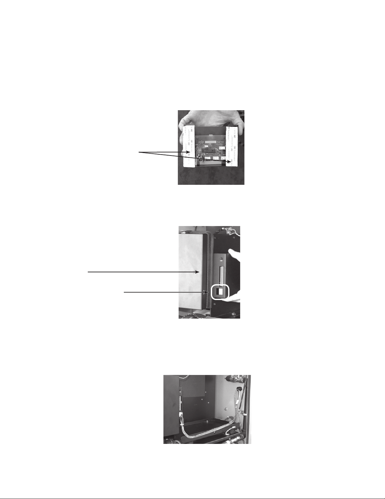
1.2.1 Installing Alarm Housing
1. Disconnect and remove Ignition Battery.
2. Install the Fuel Quantity Alarm Relay PCB and mounting bracket by removing
3. Connect P1 of wire harness (Alpha P/N 875-419-20-XXX) to J1 of the Fuel
fastener backing and pressing module into place on a clean surface on the the
side of the ECM housing.
Remove backing
Fig. 1-1, Alarm Housing Fastener Strips
Quantity Alarm Relay PCB as shown below
Attach to side of ECM housing
Connect P1 here
Fig. 1-2, Alarm Housing Placement
4. Route cable along front of battery tray and secure with cable tie.
12
Fig. 1-3, Cable Routing
745-738-C0-001 Rev. A
Page 13
1.2 Installation, continued
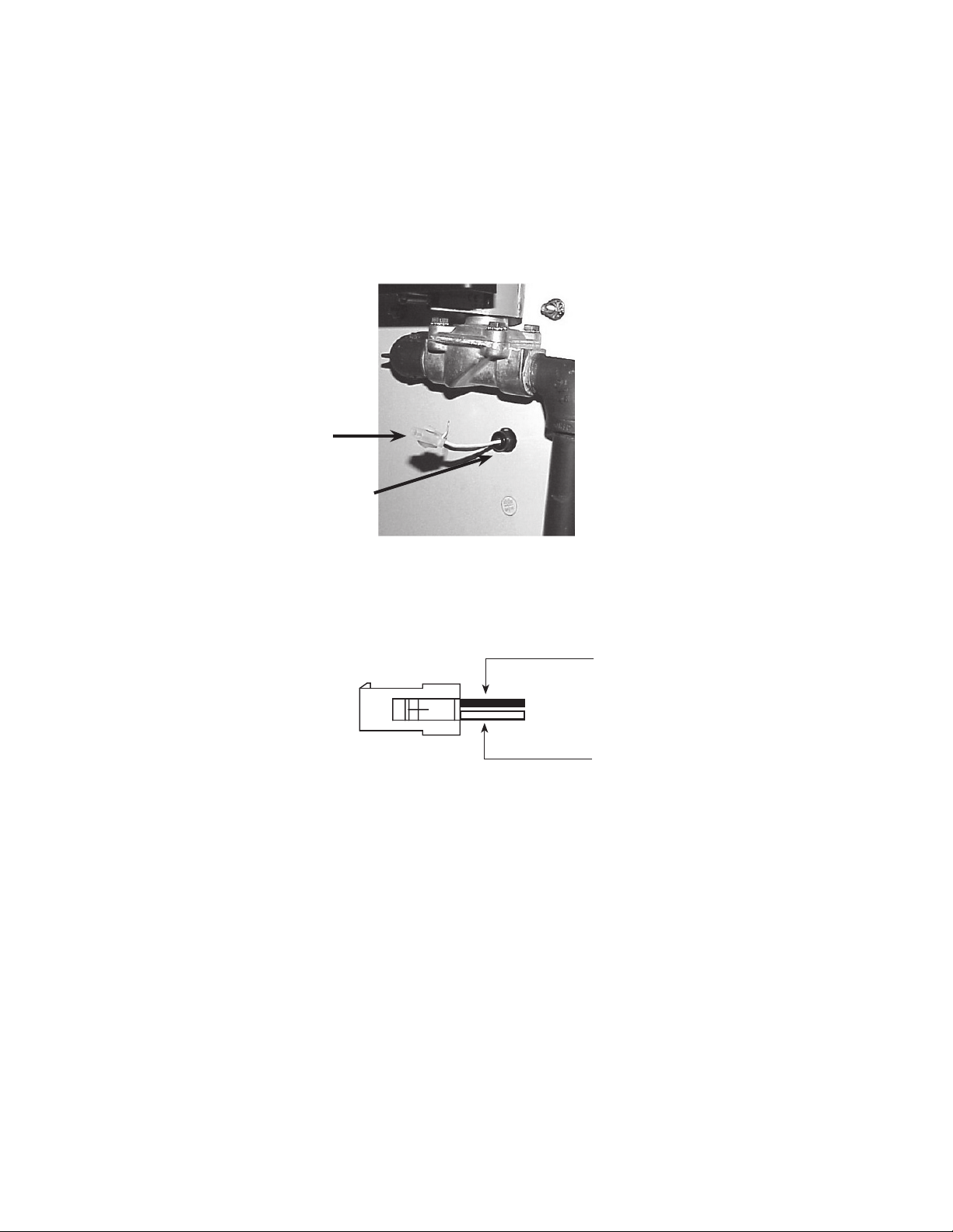
1.2.2 Removing Low Fuel Pressure Switch Connector
1. Use AMP contact extraction tool (P/N189727-1) and remove the Low Fuel
Pressure Switch (LFPS) connector. Retain connector for reassembly
2. Remove bulkhead fi tting.
LFPS connector
Bulkhead fi tting
Fig. 1-4, LFPS Connector, Bulkhead Fitting
Pin 1
Black Wire
Pin 2
White Wire
Fig. 1-5, LFPS Connector Wiring
13745-738-C0-001 Rev. A
Page 14

1.2 Installation, continued
1.2.3 Gas Box Modifi cation
1. To make room for drilling, loosen fl are fi tting and rotate LFPS to the right.
Pivot assembly
2. Pull the black and white LFPS wires through to the gas utility box enclosure. Take
care not to damage the connector contacts.
3. Loosen the existing bulkhead fi tting and remove.
Loosen fi tting
Fig. 1-6, LFPS Assembly
4. Use #4 UNIBIT to enlarge and deburr the LFPS wire hole to 7/8".
Enlarge to 7/8" dia.
5. Drill and deburr 7/8" dia. opening in bottom of gas box as indicated in Fig. 1-8.
6. Clean metal shavings from gas box and install strain relief connector.
7/8" dia. opening
for Strain Relief
Connector
Fig. 1-7, LFPS Wiring, Bulkhead Fitting
+
Existing opening
for braided hose
14
3.00"
3/4"
Fig. 1-8, Outside Bottom View, Gas Utility Box
745-738-C0-001 Rev. A
Page 15

1.2 Installation, continued
1.2.4 Cable Connection and Routing
1. Individually route sensors through fi tting nut at this time.
2. Install the NPT 1/2" water tight bulkhead fi tting.
Fig. 1-9, Sensors and Nut
Enclosure side Gas Box side
Fig. 1-10, Watertight Bulkhead Fitting
3. Individually route each sensor through the bulkhead fi tting. Do not attach nut at
this time.
4. Pull 54" of cable through the fi tting and route through the strain relief connector at
the bottom of the gas box.
NOTE
The sensors will be attached to the "remote ready" dials upon completion of the modifi cations to the gas box.
Enclosure side
Gas box side
Fig. 1-11, Sensor Modules and Bulkhead Fitting
15745-738-C0-001 Rev. A
Page 16

1.2 Installation, continued
1.2.4 Cable connection and Routing, continued
5. Tighten strain relief for sensor module cables.
6. Route the LFPS wires through the bulkhead fi tting and nut. Pivot LFPS assembly
to original position and retighten (fi nger tight plus ¼-turn) the fl are fi tting.
LFPS Wires
Tighten strain relief
Fig. 1-12, Wiring Inside Gas Box
Tighten fi tting
Pivot LFPS
assembly
Fig. 1-13, Reposition LFPS
7. Use AMP contact insertion tool (P/N 91002-1) to reattach LFPS connector.
Tighten the sealing nut on the watertight fi tting at this time.
Tighten nut
LFPS Connector
Fig. 1-14, Wire Arrangement, Generator Cabinet Side
NOTE
Before returning the system to service, all gas fi ttings must be leak tested and leak tight.
16
745-738-C0-001 Rev. A
Page 17

1.2 Installation, continued
1.2.5 Sensor Module Installation
Install the LP1 and LP2 Module (part of the
wire harness) onto the respective cylinders
using the following instructions:
1. Remove the dust cap by sliding it from
the dial, and clean the cavity under dust
cap
NOTE
Debris in the cavity prevents the module from properly
seating and accurately sensing the fuel level.
2. Slide module into slot on dial from edge
of dial. Do not attempt to install module
vertically.
Fig. 1-15, Dust Cap Removal
3. Apply thumb pressure in area provided
and push module toward center of
dial until it snaps in place. Repeat
procedure for second tank. Connect
other end of wire harness to J1 of Fuel
Relay PCB.
To remove the module, apply slight upward
pressure on the wire side of the module,
apply thumb pressure and slide module to
the outer edge of the dial.
Fig. 1-16, Sensor Module Installation
Fig. 1-17, Completed Sensor Installation
17745-738-C0-001 Rev. A
Page 18

1.2 Installation, continued
1.2.6 Reinstall Ignition Battery
1. Place Ignition Battery on battery tray.
2. Connect “Ignition Battery Positive” and “Ignition Battery Negative” leads from the
Alarm Relay wiring harness with the respective positive and negative Ignition
Battery cables. At this time, the Green LED (lower LED) on the Alarm Relay
housing will blink. This indicates the Alarm Relay is receiving power.
18
Fig. 1-18, Completed Alarm Kit Installation
745-738-C0-001 Rev. A
Page 19

1.3 Alarm Operation
After completion of the installation instructions the Fuel Quantity Alarm will be operational. Verify
green LED is on and blinking. This is the PCB “heartbeat” indicating the PCB is operating.
The RED LED is an alarm LED. The red LED will be lit when the Fuel quantity is less than ½ of total
fuel in any combination (i.e., if LP1 is full and LP2 is empty, or if both tanks are half empty).
NOTE
If both modules are not installed on the cylinders there will be no alarm. If one MODULE is disconnected and
one is still connected there will be an alarm.
The fi gure below shows the wiring between J1 of the Fuel Quantity Alarm PCB, the ignition battery
and the fuel gauge dials on the LPG tanks in the CE-G compartment.
To J1,
Fuel Relay
PCB
PIN 8 IGN BATT NEGATIVE
PIN 7 IGN BATT POSITIVE
PIN 6 LP2 SENSOR GROUND
PIN 5 LP2 SENSOR 5V SUPPLY
PIN 4 LP2 SENSOR OUTPUT
PIN 3 LP1 SENSOR GROUND
PIN 2 LP1 SENSOR 5V SUPPLY
PIN 1 LP1 SENSOR OUTPUT
Fig. 1-19, Fuel Quantity Alarm Wiring Harness
LP2 SENSOR
LP1 SENSOR
CE3G COMPARTMENT
19745-738-C0-001 Rev. A
Page 20

1.3 Alarm Operation, continued
The fi gure below shows the wiring of J2, of the Fuel Quantity Alarm PCB connector.
1
2
3
4
5
6
7
8
9
10
11
12
13
14
15
16
HALF TOTAL FUEL LEVEL (NO)
HALF TOTAL FUEL LEVEL RETURN
HALF TOTAL FUEL (NC)
BLANK
BLANK
BLANK
BLANK
BLANK
BLANK
BLANK
BLANK
BLANK
BLANK
BLANK
BLANK
BLANK
Fig. 1-20, J2, Fuel Relay PCB Connector
1.4 Return unit to Service
1. Restore gas pressure by opening both cylinders valves.
2. Use approved leak detection solution and test all gas fi ttings for leaks.
3. Verify all tools removed from cabinets.
4. Replace cabinet doors.
5. Restart Generator in accordance with start-up procedures in appropriate generator
document.
6. Verify normal system operation at headend.
20
745-738-C0-001 Rev. A
Page 21

Page 22

Alpha Technologies
Power
Alpha Technologies
3767 Alpha Way
Bellingham, WA 98226
USA
Tel: +1(360) 647-2360
Fax: +1(360) 671-4936
Web: www.alpha.com
Alpha Technologies Ltd.
4084 McConnell Court
Burnaby, BC, V5A 3N7
CANADA
Tel: +1(604) 430-1476
Fax: +1(604) 430-8908
Alpha Technologies
Europe Ltd.
Cartel Business Estate
Edinburgh Way
Harlow, Essex CM20 2TT
UNITED KINGDOM
Tel: +44-1279-422110
Fax: +44-1279-423355
Alpha Technologies
Hansastrasse 8
D-91126 Schwabach
GERMANY
Tel: +49-9122-79889-0
Fax: +49-9122-79889-21
Alphatec, Ltd
P.O. Box 56468
Limassol, Cyprus
CYPRUS
Tel: +357-25-375675
Fax: +357-25-359595
Alpha Technologies
5 Avenue Victor Hugo
F-92140 Calmart France
FRANCE
Tel: +33-3-41-90-07-07
Fax: +33-1-41-90-93-12
Copyright © 2005 Alpha Technologies, Inc. All rights reserved. Alpha is a registered trademark of Alpha Technologies. 745-738-C0-001 Rev. A.
Due to continuing product improvements, Alpha reserves the right to change specifi cations without notice.
 Loading...