

Page 1
Installation Instructions
CD Ridge Flue Terminal Assembly
(Kit Part No. 6.2000530 - Copper Brown colour)
(Kit Part No. 6.2000540 - Grey Brown colour)
Only for use with an Alpha CD/HE Condensing Boiler
with an Alpha CD Concentric (60/100) Flue System
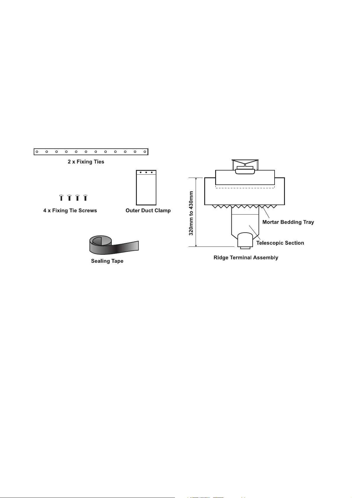
KIT CONTENTS
1. GENERAL
Note: The CD Ridge flue terminal MUST ONLY be used with an Alpha CD or HE condensing boiler.
a. The flue system must be installed in accordance with BS 5440:1.
b. The boiler must be installed in accordance with the Installation instructions supplied with the CD/HE boiler.
c. The Ridge flue terminal assembly is equivalent to a 3 m length of flue.
d. Each 45° bend is equivalent to a 0.9 m length of flue.
Note: It is recommended not to use a 90° bend with the vertical flue.
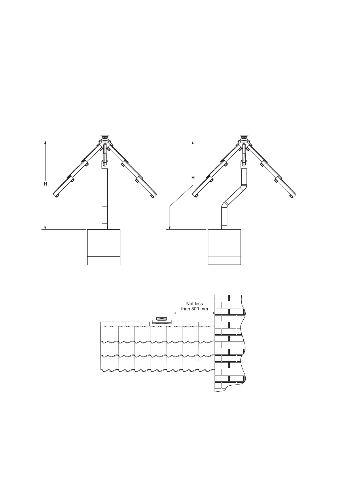
e. Refer to the vertical flue options (Fig. 1) and ensure the flue length does not exceed the equivalent of 15 m for a
CD boiler (including the terminal assembly) or 6 m for an HE boiler (including the terminal assembly).
f. Additional flue lengths of 0.75 m and 1.0 m are available for extending the flue up to the maximum equivalent flue
length.
g. To determine the actual length of flue required, measure the distance from the top of the boiler side panel to the
ridge position (H) and subtract approximately 350 mm for the terminal assembly (see Fig. 1).
h. The Ridge flue terminal has been designed predominantly for use in new build situations where roof construction
allows the terminal to be accomodated without alterations to the roof structure.
In retrofit installations roofing materials will need to be removed/replaced and the roof structure may require
alterations to accommodate the passage of the flue system.
Note: Any work of this nature should be carried out by a competent person and the integrity of the roof structure
should never be compromised.
i. The Ridge flue terminal replaces a 450 mm ridge tile. Positioning at the ridge should be in accordance with the
current Building Regulations. Cut any roofing felt/boarding as necessary to allow for the entry of the throat
section of the terminal (50 mm) to pass directly into the roof space. A clearance of 25 mm from combustible
materials must be maintained.
Page 2
j. New Build and Dry Fix Systems - There are many different proprietary dry fix and ventilated ridge systems and the
profile of the Ridge terminal is suitable for use with most forms of universal ridge tile.
Where pre-formed connections are used to mechanically fix the ridge tiles, it will be necessary to determine from the
end profile of the Ridge terminal if these are suitable. It will be necessary to trim the end profile of the terminal to
match the connector profile. Place a connector onto both ends of the terminal and install at the nominated position
between rafters.
Removal of the mortar bedding tray will be necessary if ventilation sections are used at the intersection of the ridge
tile and roof slope.
If the Ridge flue terminal is not compatible with the roofing connectors supplied, securely fix the Ridge flue terminal
to the roof structure using the fixing ties supplied and apply 'shoulders' of flexible mortar, e.g. Flexim, to either side
of the unit. Adjacent ridge tiles can then be bedded into the mortar or the adjacent roofing connectors can be
adapted to suit the situation.
Always ensure joints are fully sealed and the integrity of the roofing system is maintained.
H Max = CD 12 m
HE 3 m
Note: Always remove the flue restrictor when using the Alpha HE boiler
H Max = CD 10.2 m
HE 1.2 m
Fig. 1
Ridge Flue Terminal Kit - 2
Page 3

2. INSTALLATION
a. When the template is on the wall in the boiler position, continue the
vertical line from the centre of the flue hole up to the roof/ceiling
position. Mark the centre position of the flue hole from this line as
shown in Fig. 2.
b. Remove the telescopic section from the terminal and ensure it is
stored safely . Secure the two fixing ties to the underside of the
terminal - one either end, using the screws supplied.
c. If applicable, remove the existing ridge tile and the ridge tiles either
side then clean the area of any mortar. Refer to Fig. 3.
At the nominated position between the rafter spacings, cut the roofing
felt/boarding to allow for the penetration of the rectangular throat
section of the ridge flue terminal.
Test fit the terminal to determine how it sits in relation to adjacent roofing
materials. It may be necessary to trim the 'V' sections from the terminal
mortar bedding tray to obtain the best fit with certain roofing materials.
d. Lay cement mortar or a mortar substitute, e.g. Flexim, a flexible
mortar, at the ridge line where the Ridge terminal meets the tiles/
slates. Firmly push the ridge terminal into position allowing mortar to
penetrate the mortar bedding tray. Refer to Fig. 3.
Fig. 2
Fig. 3
e. Secure the terminal to the roof structure via the two fixing ties. Refer to Fig. 3.
f. Complete the installation of the terminal using a cement mortar or mortar substitute to make good the joint area
between the terminal and adjacent ridge tiles.
Ensure the ridge terminal is clean and free from any blockages.
Note: Once installed the terminal design will allow rain and condensate to be discharged into the flue pipe. It is
essential to connect the ridge terminal to a completed flue system connected to the boiler. If left unconnected,
provision should be made to collect liquid from the terminal and to drain it away as necessary.
g. From inside the roof, locate the previously removed telescopic section over the throat of the terminal. Lubricate the
seal if necessary.
Note: Ensure that there is adequate engagement of this section, i.e. at least 50 mm (denoted by the textured zone).
h. Assemble the flue extensions together by locating the inner duct into the seal joint and secure each extension
together with the clamps supplied (three screws). Ensure that the clamps are positioned centrally over the joints.
Refer to Fig. 4.
Note: If it is required to cut an extension, DO NOT cut the end of the inner duct that incorporates the seal joint.
Ensure the inner duct end without the seal joint is cut so that it is 15 mm longer than the outer duct.
i. Connect the flue assembly to the telescopic section of the ridge terminal using the outer clamp supplied. Seal the
telescopic joint with the tape supplied.
Note: Ensure that the flue assembly is supported at roof level using suitable brackets.
Ridge Flue Terminal Kit - 3
Page 4

Table 1
Fig. 4
Boiler
CD/HE
CD13/18R
CD24R
CD50
X (mm)
165
160
130
235
Alpha Therm Limited.
Nepicar House, London Road, Wrotham Heath,
Sevenoaks, Kent TN15 7RS
Tel: 0870 3001964
These instructions have been carefully prepared but we reserve the right to
alter the specification at any time in the interest of product improvement.
© Alpha Therm Limited 2005.
email: info@alphatherm.co.uk
website: www.alpha-boilers.com
Manual compiled and designed by Publications 2000 - Tel: (01670) 356211
Part No. 07.896.34.22
09/05/D191
 Loading...