

Page 1
Assembly Instructions
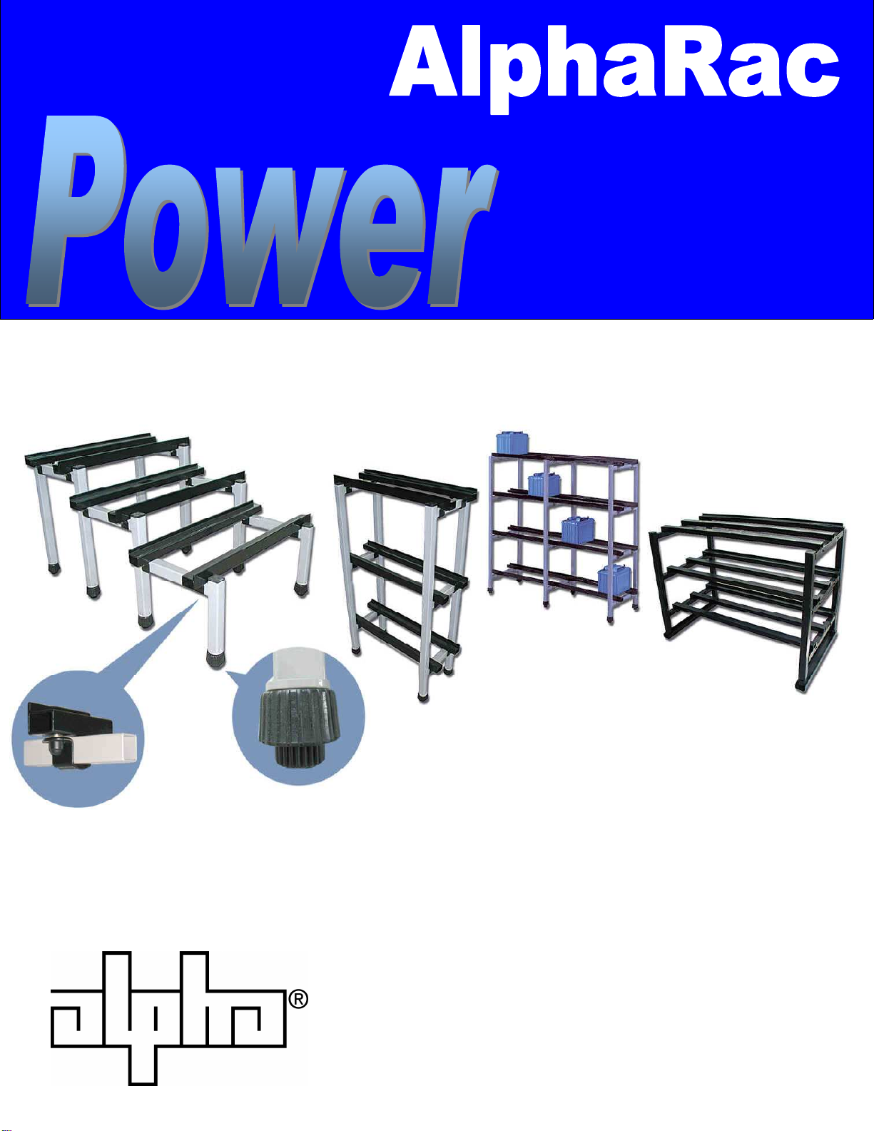
Battery Racks
Battery Racks and Cabinets
Alpha Industrial Power Inc
Effec
tive: May 2008
Page 2

Alpha Industrial Power Inc
2
Page 3

Battery Rack Assembly Instructions
Note:
Installer is cautioned to review the drawings and illustrations contained in this manual
before proceeding. If there are questions regarding the safe operation of the installation of
the racks, please contact Alpha Industrial Power or your nearest Alpha representative.
Note:
Alpha Industrial Power shall not be held liable for any damage or injury involving it’s
enclosures, power supplies, generators, batteries, or other hardware if used or operated in
any manner or subject to any condition not consistent with its intended purpose, or is
installed or operated in an unapproved manner, or improperly maintained.
Contacting Alpha Industrial Power:
www.alpha.com
OR
For general product information and customer service (8AM to 5PM, Eastern Time) call
1-800-996-6104
For complete technical support, call
1-800-996-6104
3
Page 4

1.0 Introduction
These instructions detail the proper assembly of Alpha battery racks.
Note:
Use a crew of at least two persons trained in handling, installing, operating, and maintaining
batteries and battery systems to assemble the battery racks. Rack components must be
assembled and secured on-site in accordance with these assembly instructions and all applicable
codes and laws.
During assembly procedure, do not tighten the hardware until the final step. This will
prevent hole alignment problems due to tolerance stacking. Once the battery rack is
assembled, tighten all the hardware to its specified torque.
1.1 Tools required:
Chalk line
13mm wrench
Torque wrench (0-250 in-lbs)
13mm socket
Concrete drill with bit for anchor bolts (when applicable)
Level
Multimeter (grounding verification)
Measuring Tape
Note:
Inspect contents upon receipt. If items are damaged or missing, immediately contact Alpha
Industrial Power and the shipping company. Most shipping companies have only a short claim
period.
Do not proceed with the installation of the battery rack if parts are missing or damaged.
4
Page 5

1.0 Introduction, continued
1.1 Parts List
Please refer to the bill of material enclosed with each rack. Each battery rack is
unique and will contain different parts for each configuration
1.2 Pre-installation
Note:
The following items must be addressed prior to assembly and installation.
Installation Considerations
Anchoring
Codes
Grounding
Location
Battery Installation Procedure
To provide stability and safety, securely anchor all battery racks
to the floor in accordance with applicable codes
Ensure observance of all applicable codes.
Ground the rack in accordance with all applicable codes.
Locate the racks in a clean, cool, dry place where they will not
be affected by sources of heat or sunlight. Adequate ventilation
must be provided. DO NOT install the rack in an airtight
enclosure or room with no ventilation. The floor must be level,
and capable or supporting the weight of the battery rack and the
batteries, in addition to any other equipment.
DO NOT install batteries until the rack has been properly and
completely installed. Know the polarities and terminal
placement of each battery and coordinate its location prior to
installation. Unless otherwise instructed, begin the installation
of the batteries at the center of the bottom row and work out to
each end. Install the batteries on the lowest shelves first and
work upward. If necessary, use only a small amount of water or
unscented talcum powder to help reduce friction on the
shelving. DO NOT use any lubricating agent to help slide
batteries into place.
Seismic/Earthquake Protected
Design
Maintenance
Perform in accordance with applicable local, state and national
codes.
Make periodic inspections of the entire rack for any signs of acid
corrosion. If found, the acid must be neutralized. If left
unattended, the corrosion could weaken areas of the rack.
Periodically check to see If the rack remains properly grounded
and anchored.
5
Page 6

2.0 Assembly Procedure
2.1 Determine the type of battery rack you are installing.
Every battery rack will be marked with the rack type, depth of the rack and the
length of the battery rack.
2P – 350 / 2700
Total Length of the rack in mm
Total Depth of the rack in mm
Battery Rack Type (see section 2.2)
1P ~ 1 Battery Row
Depths(B): 250; 350; 450; 550; 650
3P ~ 3 Tier – single row
Depths(B): 350; 650
2P ~ 2 Tier – single row
Depths(B): 350; 500; 550; 650
4P ~ 4 Tier – single row
Depths(B): 500
6
Page 7

2.1 Rack Type continued
2G ~ 2 Step
Depths(B): 470; 570; 670; 870
4G ~ 4 Step
Depths(B): 1110
3G ~ 3 Step
Depths(B): 690; 990; 1260
2P - 2G ~ 2 Tier - 2 Step
Depths(B): 470; 670
7
2P - 3G ~ 2 Tier - 3 Step
Depths(B): 670; 690
2P - 4G ~ 2 Tier – 4 Step
Depths(B): 1110
Page 8

NOTE: Frames may or may not be equally spaced
Outside Rail
2.2 Identify the parts required to construct the battery rack.
Angle Clip “L”
Mid-Support Rail
Angle Clip “D”
2.3 Utilizing the footing layout diagram assemble the frames.
Support Foot
M8 Hex Nut
M8 x 20 Bolt
8
Page 9

Outside rail
M8 Bolt
2.4.1
2.4 Assemble the rails to the frame
Figure 2.4.2
Figure 2.4.4
Figure 2.4.1
Figure 2.4.3
Attach the rail to the frame with
one angle clip “L” and 2 each M8 Bolts
Outside Rail
Frame
Angle Clip “L”
M8 Bolt
Intermediate Frame
2.4.2 Attach the rail to the intermediate
frame with one angle clip “L” &
2 each M8 bolts
Angle Clip “L”
9
Outside rail
Page 10

Angle Clip “D”
Angle Clip “D”
2.4.3 Attach the diagonal cross rack bracing ( All assemblies will not have bracing)
Diagonal
Brace
M8 Nut
Frame
2.4.4 Level Rack by adjusting the insulated foot.
M8 Bolt
10
Page 11

support rails
2.4.5 Installation of middle support rail (if required)
2.4.6 At this time, verify or torque all hardware to 75 in-lbs (8Nm)
2.4 Installation is now complete for Standard battery racks and the rack is ready for
battery installation. Follow the battery layout provided for you installation to install the
battery system.
One or more midmay be required. Space
evenly between outside rails
Install procedure same as
outside rails. (2.4.1 & 2.4.2)
Note:
For Seismic battery rack installation continue to section 3.0
11
Page 12

3.0 Seismic Battery Hardware Installation
Note:
For Seismic battery rack installation, perform steps 2.4.1 through 2.4.6. On seismic racks
the insulated foot is replaced with a floor flange for bolting the battery rack to the floor.
After battery installation follow seismic battery installation instructions.
3.1 Identify the individual components of the seismic installation.
Wing Nut
Battery Hold-down Angle Bar
Flat Washer
Fixing Rod
Length varies by battery
3.2 Some racks may need the installation of the seismic flange to the frame (see figure
3.2.A). With the beveled hole facing down install with the flat head bolt to frame leg.
Install the M8 anchor bolts into the slots on the floor foot flange (figure 3.2.B). Pre-drill
the anchor holes per the footing layout in section 2.3. When anchor bolts supplied by
factory – torque the bolts to 221 in-lbs (25Nm) into concrete floor. For all other
surfaces please refer to all local and state building codes.
Figure 3.2.A
Figure 3.2.B
12
Page 13

3.3 Install the batteries onto the racks.
Fixing rod
Battery width + 10mm
Note:
When installing the batteries leave a 10mm spacing between cells to accommodate the
fixing rods during the seismic hardware installation.
3.4 Layout the battery hold-down angle bars to verify installation position
Holes are spaced differently
on each side.
3.5 Position the hold-down angle bars onto the batteries. Align the fixing rods with the
holes and hook the rod under the outside rail.
Outside rail
13
Page 14

Washer
Figure 3.6.A
3.6 Feed the fixing rod through the holes in the hold-down angle bar. Insert washer and
install wing nut until hand tight as shown in figure 3.6.A. Fixing rods are installed in
opposite directions on every-other battery spacing (see figure 3.6.B & 3.6.C)
Wingnut
Hold-down angle bar
Fixing Rod
Figure 3.6.B
Figure 3.6.C
3.7 Installation is now complete for Seismic battery racks.
Note:
Manufacturer shall not be liable for, and user shall indemnify and save manufacturer harmless from any and
all claims and liabilities arising out of the use, maintenance, transportation, or installation of any equipment
warranted hereunder. The foregoing limited warranty is in lieu of all warranties express or implied, including
any warranty of merchantability or fitness for a particular purpose. Manufacturer shall not have any liability for
any special, incidental, indirect, or consequential damages.
This limited warranty applies only to the original purchaser (user) of the equipment, is non-transferable, and is
governed by and construed under the Washington State laws.
14
Page 15

15
Page 16

Alpha Technologies
Power
®
Alpha Technologies
3767 Alpha Way
Bellingham, WA 98226
USA
Tel: +1 360 647 2360
Fax: +1 360 671 4936
Web: www.alpha.com
Alpha Technologies Inc.
G.B. Enterprises Inc.
Alpha Industrial Power Inc.
1075 Satellite Blvd NW,
Suite 400
Suwanee, GA 30024
United States
Tel: +1 678 475 3995
Fax: +1 678 584 9259
USA
Tel: +1 360 647 2360
Fax: +1 360 671 4936
Web: www.alpha.com
Alpha Technologies Ltd.
4084 McConnell Court
Burnaby, BC, V5A 3N7
CANADA
Tel: +1 604 430 1476
Fax: +1 604 430 8908
Alpha Technologies
Europe Ltd.
Twyford House
Thorley
Bishop's Stortford
Hertfordshire
CM22 7PA
UNITED KINGDOM
Tel: +44 0 1279 501110
Fax: +44 0 1279 659870
Alpha Technologies GmbH
Hansastrasse 8
D 91126 Schwabach
GERMANY
Tel: +49 9122 79889 0
Fax: +49 9122 79889 21
Alphatec, Ltd
P.O. Box 56468
Limassol, Cyprus
CYPRUS
Tel: +357 25 375675
Fax: +357 25 359595
AlphaTEK ooo
Khokhlovskiy Pereulok 16
Stroenie 1, Offi ce 403
109028 Moscow
RUSSIA
Tel: +7 495 916 1854
Fax: +7 495 916 1349
Alphatec Baltics
Konarskio G. 48
2009 Vilnius
LITHUANIA
Tel: +370 5 213 8822
Fax: +370 5 213 7799
Alpha Technologies
9, Impasse Sans Souci
92140 Clamart France
FRANCE
Tel: +33 141 900 707
Fax: +33 141 909 312
Copyright © 2008 Alpha Technologies, Inc. All rights reserved. Alpha is a registered trademark of Alpha Technologies. 745-680-B4-003 Rev. C.
Due to continuing product improvements, Alpha reserves the right to change specifi cations without notice.
 Loading...