

Page 1
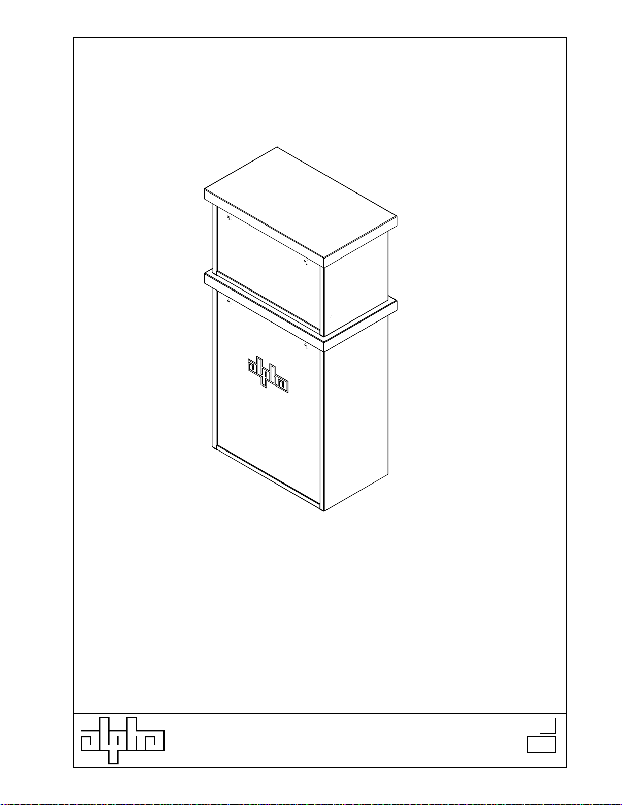
Battery Enclosure (BE) installation
procedure on UPE Enclosure
ALPHA TECHNOLOGIES
DOCUMENT NO.
033-074-C0-001
Revision
Page
A
1
Page 2

Battery Enclosure (BE) installation
procedure on UPE Enclosure
Battery Safety Notes
Electrical Hazards
Battery systems represent a risk of electrical shock and high short circuit currents. The following
precautions should be observed when maintaining VRLA (Valve-regulated Lead Acid) batteries:
1. Remove all personal metal objects (watches, rings, etc.)
2. Use insulated tools.
3. Wear eye protection and rubber gloves.
4. Observe circuit polarities.
5. Do not make or break live circuits.
6. Prior to handling batteries on a metal rack, assure the battery is not
7. Do not lay metal tools and hardware on top of the batteries.
8. As appropriate, use an insulating blanket to cover exposed portions of the battery
Certain types of rectifier circuits used in charging VRLA batteries may not include a line isolating
transformer. In these cases, extreme caution should be exercised when maintaining and collecting data
on the battery system.
The VRLA battery is sometimes enclosed in cabinets with very limited access. Again, extreme caution
must be exercised when maintaining and collecting data on the battery system.
inadvertently grounded by observing the ground fault detector indicator. In its
absence, measure the voltage between the battery and the rack. It should be
zero. If not, determine the cause and correct prior to proceeding.
system when performing extended maintenance that could result in personal or equipment
contact with the energized conductors.
Disposal
Lead acid batteries are to be recycled. Batteries contain lead and dilute sulfuric acid. Dispose of in
accordance with Federal, State, and local regulations. Do not dispose of in a landfill, lake, or other
unauthorized location.
Chemical Hazards
Any gelled or liquid emissions from a VRLA battery is electrolyte which contains dilute sulfuric acid which
is harmful to the skin and eyes; is electrically conductive; and is corrosive.
If electrolyte contacts the skin, wash immediately and thoroughly with water. If electrolyte enters the
eyes, wash thoroughly for 10 minutes with clean water or a special neutralizing eye wash solution and
seek immediate medical attention.
Neutralize any spilled electrolyte with the special solutions contained in a spill kit or with a solution of 1
lb. bicarbonate of soda to 1 gal. of water.
Fire, Explosion, and Heat hazards
Lead acid batteries can contain an explosive mixture of hydrogen gas which can vent under
overcharging conditions.
Do not smoke or introduce sparks in the vicinity of the battery.
Prior to handling the batteries, touch a grounded metal object, such as the rack, to dissipate any static
charge that may have developed in your body.
Do not charge batteries in a sealed container. The individual batteries should have 0.5 inches of space
between them to allow for convection cooling. If contained, assure the container or cabinet and room
have adequate ventilation to prevent an accumulation of potentially vented gas.
ALPHA TECHNOLOGIES
DOCUMENT NO.
033-074-C0-001
Revision
Page
A
2
Page 3

Battery Enclosure (BE) installation
procedure on UPE Enclosure
Parts list:
Qty. Description
1 Battery Enclosure (BE) (033-074-20)
1 Y-adapter for battery cabling (p/n 874-655-20)
1 Optional, Y-configured Tamper Switch cable (p/n 874-684-21)
3 VRLA batteries (manufacturer and type to match existing batteries).
1 Battery Cable Kit, fused, (p/n 874-202-21)
Required tools:
Digital voltmeter
7/16 wrenches and sockets
Corrosion/Oxidation inhibiting paste for battery terminals
Insulated handle torque wrench and 7/16 socket
Initial torque settings: 110 inch-lbs
Rework torque settings: 75% of original
ALPHA TECHNOLOGIES
DOCUMENT NO.
033-074-C0-001
Revision
Page
A
3
Page 4
Battery Enclosure (BE) installation
procedure on UPE Enclosure
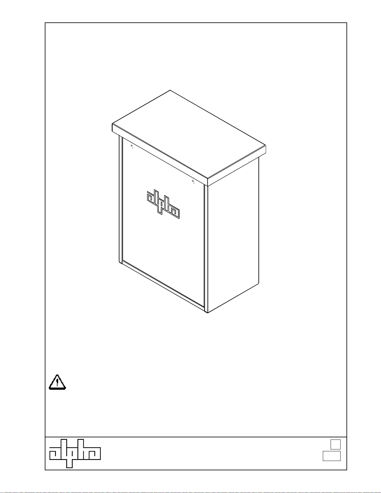
Unpack the Battery Enclosure (BE) and inspect for damage.
ALPHA TECHNOLOGIES
DOCUMENT NO.
033-074-C0-001
Revision
Page
A
4
Page 5
Battery Enclosure (BE) installation
procedure on UPE Enclosure
Procedure for adding Alpha Technologies Battery Enclosure (BE) to
existing UPE enclosures:
1. Begin with a UPE enclosure system which is currently not on-line.
CAUTION:
The total installed weight of the system is
approximately 600 lbs. Verify the stability of the
system before loading additional batteries.
Revision
Page
ALPHA TECHNOLOGIES
DOCUMENT NO.
033-074-C0-001
A
5
Page 6

Battery Enclosure (BE) installation
procedure on UPE Enclosure
2. Remove the front door of the enclosure and set aside (Internal
components not shown for clarity).
DOCUMENT NO.
ALPHA TECHNOLOGIES
033-074-C0-001
Revision
Page
A
6
Page 7

Battery Enclosure (BE) installation
Wing nut location
procedure on UPE Enclosure
3. Remove the wing nuts from each of the front corners of the lid of
the UPE. Set the lid aside.
Revision
Page
ALPHA TECHNOLOGIES
DOCUMENT NO.
033-074-C0-001
A
7
Page 8

Battery Enclosure (BE) installation
procedure on UPE Enclosure
4. Install the BE by engaging the retaining channel (see detail
below) on the rear lip of the cabinet. Reinstall wing nuts.
Detail of retaining channel and cabinet lip.
DOCUMENT NO.
ALPHA TECHNOLOGIES
033-074-C0-001
Revision
Page
A
8
Page 9

Battery Enclosure (BE) installation
procedure on UPE Enclosure
The steps outlined below are referenced in the figure on the following
page:
5. Place three new batteries into BE-UPE and connect them with a
fused Battery Cable Kit (BCK).
6. Move the Remote Temperature Sensor (RTS) at this time, and
secure it to the center of the middle battery on the upper battery
shelf.
7. Route the new battery cables and RTS wire down and around the
left side of the battery shelf and through the 2 conduit pass-thru
hole into the UPE power supply area.
8. Switch the Power Supply Battery Breaker OFF at this time.
NOTE: The No Battery alarm will activate when the
battery breaker is OFF. This is normal and should be
expected.
9. Unplug the original BCK from the power supply.
10. Connect the new Y-adapter to the power supply (note labels on
Y-adapter wires).
11. Connect the RTS to the appropriate power supply jack at this
time.
12. Plug the original and new BCK into the Y-adapter.
13. Switch battery breaker ON at this time.
NOTE: Once the battery breaker has been switched ON, the
No Battery alarm should self-reset (clear) within one
minute.
ALPHA TECHNOLOGIES
DOCUMENT NO.
033-074-C0-001
Revision
Page
A
9
Page 10

Battery Enclosure (BE) installation
procedure on UPE Enclosure
Long Black wire
Long Red wire
Step
7
BLK -
(moved from lower battery shelf to corresponding position in upper battery shelf)
---
+++
Wires pass through hole in Battery
Enclosure
or
RED +
Step
12
RED +
BLK -
RED +
Temperature Sensor
Step
6
R.T.S connector to logic card
Step
or input jack module
11
(dependant upon model options)
BLK -
RED +
Step
Newly-installed batteries in upper
Step
Fuse
5
Spacer
Battery Enclosure (BE)
Step
8
Step
13
XMS2 battery connections
10
RED +
Step
9
BLK -
Wires pass through hole in shelf.
Long Black wire
Long Red wire
ALPHA TECHNOLOGIES
BLK -
Step
12
“Y”-adapter
(p/n 874-655-20)
Allows the connection of two parallel
battery strings to one XM or XMS2 power
supply.
---
+++
DOCUMENT NO.
033-074-C0-001
XM battery connections
Existing batteries in UPE enclosure
Revision
Page
A
10
Page 11

Battery Enclosure (BE) installation
procedure on UPE Enclosure
12. Install original lid on top of BE-UPE.
DOCUMENT NO.
ALPHA TECHNOLOGIES
033-074-C0-001
Revision
Page
A
11
Page 12

Battery Enclosure (BE) installation
procedure on UPE Enclosure
a.
b.
c.
Dual Closed-loop magnetic tamper switch
a. Top enclosure switch. Mounted to side flange with 2 #6-32
screws.
b. Top enclosure magnet. Mount to door studs with 2 #6-32
KEPS nuts.
c. Shelf cutouts may vary.
d. Bottom enclosure magnet. Mount to door studs with 2 #6-32
KEPS nuts.
e. Bottom enclosure switch. Mount to top shelf with 2 #6-32
screws.
f. 2-pin connector, plugs into XM/XMS2 or transponder.
ALPHA TECHNOLOGIES
e.
d.
DOCUMENT NO.
033-074-C0-001
f.
Revision
Page
A
12
Page 13

Battery Enclosure (BE) installation
procedure on UPE Enclosure
13. Install door on BE-UPE.
ALPHA TECHNOLOGIES
DOCUMENT NO.
033-074-C0-001
Revision
Page
A
13
Page 14

Battery Enclosure (BE) installation
procedure on UPE Enclosure
14. Replace door on UPE.
End of Installation Procedure
ALPHA TECHNOLOGIES
DOCUMENT NO.
033-074-C0-001
Revision
Page
A
14
Page 15

Battery Enclosure (BE) installation
procedure on UPE Enclosure
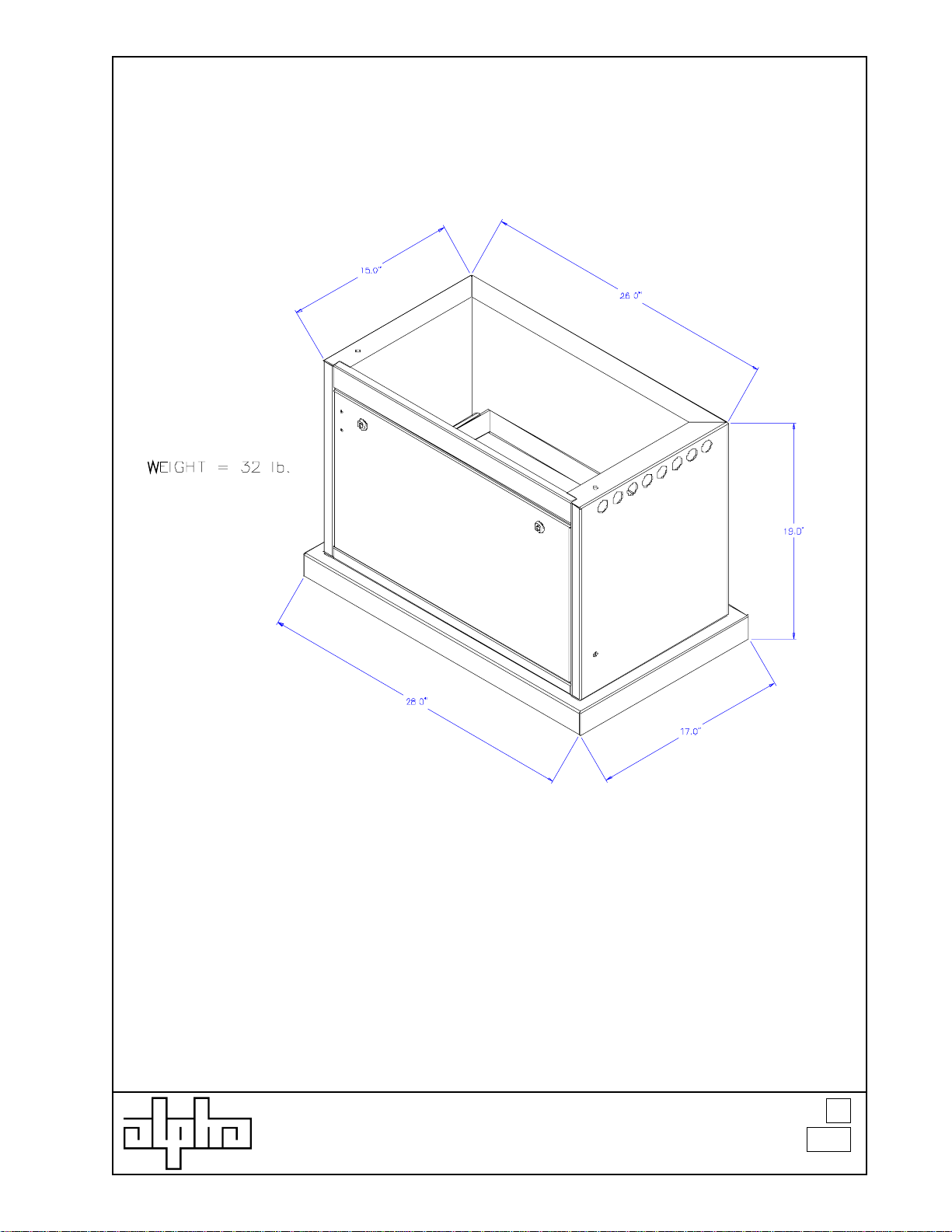
17.0"
28.0"
52.0"
26.0"
15.0"
15. Overall dimensions of completed enclosure assembly
DOCUMENT NO.
ALPHA TECHNOLOGIES
033-074-C0-001
Revision
Page
A
15
 Loading...