

Page 1
Cable Series
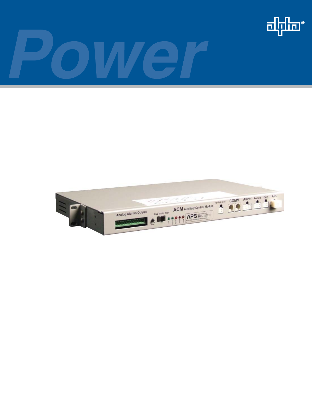
APU Control Module (ACM)
Operation and Maintenance Manual
Effective: February 2010
Alpha Technologies
Page 2

Alpha Technologies
Power
®
Page 3

APU Control Module
Operation and Maintenance Manual
018-340-B0-001, Rev. A
Effective Date: February, 2010
Copyright© 2010
Alpha Technologies, Inc.
member of The Group
NOTE:
Photographs contained in this manual are for illustrative purposes only. These photographs may not match
your installation.
NOTE:
Operator is cautioned to review the drawings and illustrations contained in this manual before proceeding. If
there are questions regarding the safe operation of this powering system, please contact Alpha Technologies
or your nearest Alpha representative.
NOTE:
Alpha shall not be held liable for any damage or injury involving its enclosures, power supplies, generators,
batteries, or other hardware if used or operated in any manner or subject to any condition not consistent with
its intended purpose, or is installed or operated in an unapproved manner, or improperly maintained.
TM
Contacting Alpha Technologies: www.alpha.com
or
For general product information and customer service (7 AM to 5 PM, Pacifi c Time), call
1-800-863-3930,
For complete technical support, call
1-800-863-3364
7 AM to 5 PM, Pacifi c Time or 24/7 emergency support
Page 4

Table of Contents
Safety Notes ..........................................................................................................................6
Battery Notes .........................................................................................................................7
1.0 System Overview ........................................................................................................ 8
1.1 Introduction ...................................................................................................... 8
1.2 Theory of Operation ......................................................................................... 9
1.2.1 Normal Operating Condition.................................................................. 9
1.2.2 Standby Operating Condition (Less Than 10 Minutes) ......................... 9
1.2.3 Standby Operating Condition (More Than 10 Minutes) ......................... 9
1.2.4 Normal APU Shutdown ....................................................................... 10
1.2.5 Abnormal APU Shutdown.................................................................... 10
2.0 Installation, Confi guration and System Interface .......................................................11
2.1 Field Installation ..............................................................................................11
2.2 ACM-96 and ACM-96G .................................................................................. 12
2.2.1 A2304 Controller Confi guration ........................................................... 12
2.2.2 APS-CP Confi guration ........................................................................ 13
2.2.3 ECI-2 Confi guration............................................................................. 13
3.0 Indicators, Controls and Connectors ........................................................................ 14
3.1 Indicators ....................................................................................................... 15
3.2 Control Functions ...........................................................................................16
4.0 Alarms and Notifi cations ...........................................................................................17
4.1 Alarms ............................................................................................................ 17
4.2 Notifi cations ................................................................................................... 19
4.3 Analog Transponder Interface........................................................................ 20
4.4 Standard ACM-Transponder Interconnection ................................................ 21
4.5 Transponder System Block Diagram ............................................................. 22
4.6 DOCSIS Transponder Interface ..................................................................... 23
5.0 System Self-test and Maintenance ........................................................................... 24
5.1 Self-test .......................................................................................................... 24
5.2 System Maintenance ..................................................................................... 26
4
018-340-B0-001 Rev. A
Page 5

Figures and Tables
Fig. 2-1, CPS-6 Confi guration............................................................................ 11
Fig. 2-1, A2304 Dip Switch Confi guration ..........................................................12
Fig. 2-2, Y Alarms Harness ................................................................................12
Fig. 2-3, Alarms Jumper ....................................................................................12
Fig. 2-4, 5-Position APS-CP Dip Switch ............................................................13
Fig. 2-5, ECI-2 Engine Controller.......................................................................13
Fig. 3-1, ACM Front Panel .................................................................................14
Fig. 4-1, Alarms Matrix .......................................................................................17
Fig. 4-2, Alarm Filter Board ................................................................................20
Fig. 4-3, Standard Transponder-to-ACM interconnect cable, collocated
applications..........................................................................................21
Fig. 4-4, Standard Transponder to ACM-interconnect cable, remote
applications..........................................................................................21
Fig. 4-5, Transponder System Block Diagram ...................................................22
Fig. 4-6, System Interconnection Diagram ........................................................23
Table 1-1, Normal Mode Crank Cycle ....................................................................9
Table 4-1, Analog Transponder Interface .............................................................20
018-340-B0-001 Rev. A
5
Page 6
Safety Notes
Review the drawings and illustrations contained in this manual before proceeding. If there are any questions
regarding the safe installation or operation of this product, contact Alpha Technologies or the nearest Alpha
representative. Save this document for future reference.
To reduce the risk of injury or death, and to ensure the continued safe operation of this product, the following
symbols have been placed throughout this manual. Where these symbols appear, use extra care and
attention.
ATTENTION:
The use of ATTENTION indicates specifi c regulatory/code requirements that may affect the placement of
equipment and /or installation procedures.
NOTE:
A NOTE provide additional information to help complete a specifi c task or procedure.
CAUTION!
The use of CAUTION indicates safety information intended to PREVENT DAMAGE to material or
equipment.
WARNING!
WARNING presents safety information to PREVENT INJURY OR DEATH to the technician
or user.
6
018-340-B0-001 Rev. A
Page 7

Battery Safety Notes
Always refer to the battery manufacturer’s recommendation for selecting correct “FLOAT” and “ACCEPT” •
charge voltages. Failure to do so can damage the batteries.
Verify the Power Supply’s battery charger “FLOAT” and “ACCEPT” charger voltage settings.•
Batteries are temperature sensitive. During extremely cold conditions, a battery’s charge acceptance •
is reduced and requires a higher charge voltage; during extremely hot conditions, a battery’s charge
acceptance is increased and requires a lower charge voltage. To compensate for changes in temperature,
the battery charger used in the power supply is temperature compensating.
If the batteries appear to be overcharged or undercharged, fi rst check for defective batteries and then •
verify the correct charger voltage settings.
To ensure optimum performance, inspect batteries every three to six months for signs of cracking, •
leaking, or unusual swelling (note that some swelling is normal).
Check battery terminals and connecting wires. Clean battery terminal connectors periodically and •
retighten to approximately 50 inch-pounds (or to manufacturer’s specifi cations if not AlphaCells). Spray
the terminals with an approved battery terminal coating such as NCP-2.
NOTE:
If installed, disconnect the AlphaGuard prior to measuring battery voltage.
NOTE:
Even with a AG-CMT present in the system, any battery which fails the 0.3V load test must be replaced with
an identical type of battery.
Check battery voltages UNDER LOAD. Use a load tester if available. Differences between any battery in •
the set should not be greater than 0.3Vdc.
Refer to the battery manufacturer’s recommendation for correct charger voltages and the power supply •
operation manual for corresponding charger settings.
Number the batteries (1, 2, 3, etc.) inside the enclosure for easy identifi cation (refer to the appropriate •
enclosure installation guide).
Establish and maintain a battery maintenance log.•
018-340-B0-001 Rev. A
7
Page 8

1.0 System Overview
1.1 Introduction
The primary purpose of Alpha’s APU Control Module (ACM) is to control and monitor
generator systems that utilize the ACU Module. Depending upon the standby powering
confi guration, the ACM and generator combination are installed remotely, or co-located, with
other Alpha equipment such as power supplies and batteries.
The ACM monitors AC line and DC bus status to determine when to start and stop the APU.
In the event of an extended power outage, self test initiation, remote start command or low
battery bus voltage, the ACM will start the APU. The APU will prevent the backup batteries
from discharging to a reduced voltage level which would compromise the ability of the system
to provide a continuous, reliable source of power.
In addition to starting the APU, the ACM monitors the entire generator system for abnormal
operating conditions such as engine over-temperature, gas leak, enclosure pad shear, etc. If
certain abnormal conditions or alarms are present, the ACM and or the APU controller (APSCP, A2034 Logic PCB, CCG or ECI-2) will either prevent the generator from starting or shut
it down immediately. This provides for public safety, while preventing any serious damage to
the APU. The system operator also has the ability to override the ACM and control the APU
manually or remotely.
Finally, the ACM provides the interface between the APU and Alpha Technologies’
communication devices. The ACM is designed to control and monitor the APU while
responding to commands and queries from a system controller via an isolated RS-485 data
bus. Status information and alarms can be read from the ACM remotely via the data bus,
locally from the Light Emitting Diodes (LEDs) on the unit’s front panel, or by an optically
isolated analog transponder interface. The ACM is capable of reporting 7 major alarms, 6
minor alarms and 2 notifi cations.
8
018-340-B0-001 Rev. A
Page 9

1.0 System Overview, continued
1.2 Theory of Operation
1.2.1 Normal Operating Condition
Under normal operating conditions (no alarms) the ACM’s Run-Auto-Stop (RAS)
three position rocker switch will be in one of two positions: “AUTO” or “RUN”. (See
Section 3, Indicators, Controls and Connectors) The ACM has control over the
starting and stopping of the APU while in the AUTO mode. The ACM is monitoring
the utility input, via an AC sense, the DC buss voltage, Ignition battery charger
output, enclosure sensors and the APU status sent from the APU controller. If a fault
occurs, the ACM determines whether or not to start or inhibit the APU based upon
the failure. The ACM can also receive remote start commands via the RS-485 buss
or the analog transponder interface. The ACM can be removed from controlling the
APU by switch the RAS to run or “manual” mode. In this mode, the APU will run until
a fault condition shuts it down.
1.2.2 Standby Operating Condition (Less Than 10 Minutes)
If an AC line disturbance or outage is less than 10 minutes, the ACM will not start
the APU unless the battery buss voltage drops below a programmable threshold
(Low DC Buss Level) which defaults to 1.95 Volts per cell or 35.1/46.8/93.6 Volts for
36/48/96 Volt systems respectively. However, the ACM will notify the system operator
of a line failure via the front panel LED’s (see alarm section). Otherwise, the ACM will
appear to be in a “normal” operating condition.
1.2.3 Standby Operating Condition (More Than 10 Minutes)
If an AC line disturbance or outage is greater than 10 minutes, the ACM start delay
timer will expire and the ACM will attempt to start the APU. The ACM will attempt
to start the engine 9 times with either a 30 second or a 60 second pause between
attempts (See Table 1-1). If the engine fails to start, the ACM will report an “Engine
Over-crank” alarm. Otherwise, the ACM will start and continue to run the APU until
either a normal shutdown or Major alarm occurs (See section 4.1, Alarms).
Crank Cycle
Crank Attempt 1 2 3 4 5 6 7 8 9
Cranking Engine 15 Sec 15 Sec 15 Sec 15 Sec 15 Sec 15 Sec 15 Sec 15 Sec 15 Sec
Pause (no crank) 30 Sec 30 Sec 60 Sec 30 Sec 30 Sec 60 Sec 30 Sec 30 Sec
Table 1-1, Normal Mode Crank Cycle
Engine
Overcrank
Alarm
018-340-B0-001 Rev. A
9
Page 10

1.0 System Overview, continued
1.2 Theory of Operation, continued
1.2.4 Normal APU Shutdown
The ACM will initiate a normal APU shutdown when AC line is qualifi ed, DC bus
alarm is not active, the 12 minute cool-down period has elapsed, and the Engine
Run command is not active. Otherwise, the ACM will continue to run the APU until
the above conditions are met or a major alarm occurs. Also, the APU will run for a
minimum of 30 minutes if started due to low DC Bus voltage, or if the RAS switch is
switched from Run to Auto (See section 3.1, Indicators, Controls and Connectors).
1.2.5 Abnormal APU Shutdown
The ACM will immediately shutdown the APU under the following conditions:
• Major alarm
• Activation of manual engine stop switch
• Receipt of software engine stop command
• General generator failure
10
018-340-B0-001 Rev. A
Page 11

2.0 Installation, Confi guration and System Interface
2.1 Field Installation
1. Disconnect all connectors from front of ACU.
2. Remove 4 screws from ACU mounting ears
3. Install ACM in place of ACU; install 4 mounting screws to secure ACM to rack and rail.
4. Connect ACM using existing cable assemblies
018-340-B0-001 Rev. A
Fig. 2-1, CPS-6 Confi guration
11
Page 12

2.0 Installation, Confi guration and System Interface, continued
2.2 ACM-96 and ACM-96G
2.2.1 A2304 Generator Controller Confi guration
1. The A2034 logic board is located in the electronics compartment of the APU
enclosure. Locate the 4-position Dip Switch and set switch 2 in the OFF position.
For the new confi guration, switches 1 and 3 should be on, and switches 2 and 4
should be off.
Fig. 2-2, A2304 Dip Switch Confi guration
2. Remove the Y alarms harness and connect the 15 pin male mini mate-n-lock
connector directly to J2 of the 704-619 board.
Fig. 2-3, Y Alarms Harness
3. Install provided alarm jumper to J4 of the A2034 logic board.
12
Fig. 2-4, Alarms Jumper
018-340-B0-001 Rev. A
Page 13

2.0 Installation, Confi guration and System Interface, continued
2.2 ACM-96 and ACM-96G, continued
2.2.2 APS-CP Generator Controller Confi guration
Locate the Dip Switch on the APS-CP by removing the screws in the bottom corners
and lifting the front cover. If it is a 5-position Dip Switch, set switches 1 and 5 to the
ON position.
Fig. 2-5, 5-Position APS-CP Dip Switch
If it is a 4-position Dip Switch, leave default switch positions.
2.2.3 ECI-2 Confi guration
The ECI-2 Engine controller can be directly connected. No changes are required for
confi guration.
NOTE:
ACM-96G requires Genasys DC Bus Harness
Fig. 2-6, ECI-2 Engine Controller
NOTE:
ACM-48 and ACM-36 models are also available and can be installed to directly replace existing CE style
stand-alone AlphaGen ACU units.
018-340-B0-001 Rev. A
13
Page 14

3.0 Indicators, Controls and Connectors
8
APU Control Module LED Indicators and switches:
1. “Major” Alarm Indicator (Red LED)
2. “Minor” Alarm Indicator (Red LED)
3. “Notify” Indicator (Amber LED)
4. “Comm” Indicator (Green LED)
6
7
5
43
2
1
Fig. 3-1, ACM Front Panel
9
10
11
12
13
5. “System” Indicator (Green LED)
6. “Run-Auto-Stop” Switch
7. “Service/Reset” Push Button Switch
8. Analog Alarms Output
9. Communications Interface
10. Alarm: Input Signals
11. Remote: DCIU Breaker Trip
12. Battery DC Bus Input
13. APU AC/DC Power and Control Signals
The ACM user interface consists of 5 LEDs (1-5), a three-position rocker switch (6), and
a momentary contact, push-button switch (7). The Communications Interface (9) can
be used to attach an Alpha Technologies system controller. Provisions are made for
Transponder connections through the Analog Alarms Output (8). The interface with the
DOCSIS transponder platform is with an offset data cable from one of the parallel connected
communications ports (9).
14
018-340-B0-001 Rev. A
Page 15

3.0 Indicators, Controls and Connectors, continued
3.1 Indicators
The Major and Minor alarm LEDs (1, 2) are red and refl ect the state of the discrete major and
minor alarms monitored by the ACM. A Major alarm indicates failure of a critical component
or some other situation (pad shear, for example) where the system either has gone off-line,
or system failure and/or shutdown is imminent. Major alarms cause the engine to shutdown
immediately and generally prevent further operation. Most major alarms are latched by the
ACM. A site check by service personnel is required to repair the fault and clear the system. A
Minor alarm indicates a system fault which, though not indicative of imminent system failure
or shutdown, requires service attention as the fault condition could worsen leading to a shut
down the system. A site check by service personnel is recommended. The amber Notify LED
(3) represents status information that is not signifi cant enough to be classifi ed as an alarm.
At present, only two items fi t into this category: AC line status and Engine Service Required.
The Communications LED (4) illuminates for two seconds after each communications session
on the Alpha bus. This is a standard that is used throughout the Alpha bus communications
system. The green System status LED (5) indicates that the microprocessor has power and is
operating normally. This LED fl ashes at a 1 Hz rate with a 50% duty cycle. When the ACM is
in factory test mode, this LED will fl ash at a 0.5 Hz rate.
018-340-B0-001 Rev. A
15
Page 16

3.0 Indicators, Controls and Connectors, continued
3.2 Control Functions
RUN-AUTO-STOP Switch: The three positions of the rocker switch (6) are RUN, AUTO
and STOP (RAS). The RAS switch is normally left in the center, AUTO, position so that the
ACM has control of the generator set. A minor alarm is indicated when the RAS switch is not
in the AUTO position. The STOP (“left”) position is used to stop or prevent APU operation
during maintenance. Placing the RAS switch in the STOP position for three (3) seconds, then
switching back to AUTO will clear any latched alarms and start the generator if the cause of
the alarm has been corrected. Placing the RAS switch in the RUN (“right”) position will cause
the engine to start and run until this switch is released to AUTO.
The engine will not shut down immediately when the switch is returned to AUTO from RUN;
there is a 30-minute cool down, and the ACM’s shutdown criteria must be met in order to
shutdown the engine. Also, each time the RAS switch is placed in the AUTO position (from
the STOP position), the ACM will start and run the APU for one minute after a short delay.
Service/Reset Push Button Switch: The service reset push button switch (7) has two
purposes:
It resets the engine service timer when depressed for 5 seconds. The service interval is 1.
a programmable counter within the ACM that defaults to 100 hours after the initial 25hour break-in period. When 100 hours of engine run time elapses, the Service Required
notifi cation is set and the notifi cation LED illuminates. After the engine has been serviced,
pressing and holding the service reset switch for 5 seconds will reset the 100-hour
service counter. All of the LEDs fl ash, while the switch is depressed, until a fi ve-second
timer elapses at which time all of the LEDs remain on solid until the switch is released.
This provides feedback to the technician, indicating the effective resetting of the engine
service counter.
It can be used to determine which alarms are active. The service reset push-button is 2.
also used to obtain information about active alarms. The Major and Minor alarm LEDs
are very general and a technician will need more detailed information upon arrival to
the site of an alarming ACM. To retrieve details about an active alarm, the user presses
and releases the service-reset switch. An active alarm (Major or Minor) will be indicated
by the LEDs as indicated in Figure 4-1. Note that depressing the service-reset switch
for 5 seconds will cause the service timer to clear possibly disrupting the preventive
maintenance schedule. When the service-reset button is pressed again, the LEDs will
represent the next active alarm. Pressing the button when there are no more active
alarms will reset the LEDs to their normal usage. Several quick fl ashes of all fi ve LEDs
will indicate end of the alarm list before the LEDs return to normal operation. If the service
reset button is not depressed again when an alarm is indicated, the LEDs will return to
normal operation after 30 seconds have elapsed. Resetting alarms via status monitoring
or via the manual stop switch will also clear the alarm pattern indicated by the LEDs.
16
018-340-B0-001 Rev. A
Page 17

4.0 Alarms and Notifi cations
Major 1 2 3 4 5 6 7 8 9 10 11 15
Abbreviation OT DT OC GH
WI PS LP CF
TF IB AD
SR
Major
Minor
Notify
Comm
System
14
LF
13
DC
12
TP
1. Engine Over-Temp (OT) 9. Self-Test Fail (TF)
2. DCIU Breaker Trip (DT) 10. Low Ignition Battery
(IB)
3. Engine Over-Crank
(OC)
11. Auto-mode Disabled
(AD)
4. Gas Hazard (GH)*
12. Tamper (TP)
5. Water Intrusion (WI) 13. DC Bus fault
6. Pad Shear (PS)*
14. Line Failure (LF)
7. Low Fuel Pressure (LP) 15. Service Required (SR)
8. Control Fail (CF)
Control Fail (8), can be associated with a low oil pressure condition. Verify engine oil level prior to running or testing APU.
4.1 Alarms
The ACM is capable of reporting “Major” alarms, “Minor” alarms and “Notifi cations”. The
following are detailed descriptions of each.
Fig. 4-1, Alarms Matrix
MAJOR ALARMS:
A Major alarm indicates failure of a critical component or some other situation (pad shear,
for example) where the system either has gone off-line, or system failure and/or shutdown
is imminent. Major alarms cause the engine to shutdown immediately and generally prevent
further operation. Most major alarms are latched by the ACM. A site check by service
personnel is required to repair the fault and clear the system. Placing the RAS switch in the
STOP position for three (3) seconds, then switching back to AUTO will clear any latched
alarms and start the generator if the cause of the alarm has been corrected.
1. Engine Over-Temp (OT): Indicates engine temperature has exceeded safe limits and
operation of the unit has been suspended. The alarm is reset when the engine temperature
falls below safe limits.
2. DCIU Breaker trip (DT) (Latching): For 7.5kw DC generators with a DCIU only. The
DICU breaker has tripped because the APU alternator output voltage is too high. Operation
of the unit has been suspended. The alarm is cleared when the Reset command is issued or
when the manual stop switch is activated.
3. Engine Over-Crank (OC) (Latching): Indicates the failure of the engine to start when
commanded to do so. Clear the alarm after the DCIU breaker trip issue is resolved. To clear
the alarm initiate the Reset command or move the RAS switch to stop the return to AUTO or
RUN.
4. Gas Hazard (GH) (Latching): The concentration of hydrocarbon fuel in the power
system’s enclosure air space has exceeded safe limits or 10%-20% of the Lower Explosive
Limit (LEL) For more than three (3) or ten (10) seconds depending on the detector use. APU
operation is suspended. The alarm is cleared when the Reset command is issued or when
the manual stop switch is activated.
5. Water Intrusion (WI) (Latching if encountered while the engine is running): Water
level within the main or fuel enclosure has exceeded safe limits for generator operation. APU
018-340-B0-001 Rev. A
operation is suspended while this alarm is active. The alarm is reset when the water level falls
below maximum limits if alarm occurs while the APU is not running.
17
Page 18

4.0 Alarms and Notifi cations, continued
4.1 Alarms, continued
6. Pad Shear (PS) (Latching): Indicates that the main or fuel enclosure has shifted from
its pad mounting position. APU operation is suspended. The alarm is reset when the unit is
returned to its original position and the reset command is issued or when the manual stop
switch is activated.
NOTE:
APU will not start if Pad Shear magnet is not correctly installed below the Pad Shear sensor.
7. Low Fuel Pressure (LP) (Latching - after 5 activations): Indicates that site fuel supply
(Propane-fueled APU only) is insuffi cient for extended engine operation. The alarm is reset 5
minutes after the fuel supply is replenished.
MINOR ALARMS:
Minor alarms indicate a system fault which, though not indicative of imminent system failure
or shutdown, require service attention as the fault condition could worsen to shut down the
system. A site check by service personnel is recommended.
8. Control Fail (CF) (Latching - after 5 activations): This alarm indicates a control failure
between the ACM and the generator set. Typically this means that the engine did not start or
stop when commanded to do so. This alarm could also be an indication of Major Condition
if engine oil pressure is below safe limits and the APU’s CCG, APS-CP, A2034 or the ECI-2
control unit shuts down or suspends operation of the APU. The alarm is cleared when the
Reset command is issued or when the manual stop switch is activated.
9. Self-Test Fail (TF) (Latching): Status of most recent generator test. The alarm is cleared
when the Reset command is issued, the manual stop switch is activated or another Self-Test
command is issued.
10. Low Ignition Battery (IB): Indicates that the generator’s ignition battery voltage has
fallen below 11.5Vdc. Alarm is cleared when battery voltage rises above 12.0Vdc indicating
battery recovery has begun. Note that low ignition battery voltage is not alarmed during
engine cranking.
NOTE:
This input requires the ignition battery sense jumper to be removed and a harness installed directly from the
ignition battery terminal through a current limiting resistor, on the positive lead, to a 4 pin mini mate-n-lock
connector. If this option is not utilized do not remove the installed jumper in the ignition batt sense connector.
11. Auto Mode Disabled (AD): Indicates the position of the ACM control select switch.
When the Run-Auto-Stop (RAS) switch is in a manual (STOP or RUN) position, the ECM has
no control over engine operation and therefore raises an alarm. This is a hardware ‘lockout’
input and cannot be changed via status monitoring.
12. APU Tamper (TP): One of the doors on the APU enclosure is open. The alarm clears
when the door is closed. For confi guration with a separate APU enclosure, (such as the 7.5kw
DC APU) install the provided modifi ed Alarm harness to monitor the APU tamper separate
from the power supply enclosure tamper.
13. DC Bus Fault (DC): Indicates that the power system DC bus voltage, as measured
at the ACM, is less than 1.95 volts per cell. This alarm clears automatically when the bus
voltage exceeds 2 volts above nominal (i.e., 50Vdc in a 48V system).
18
018-340-B0-001 Rev. A
Page 19

4.0 Alarms and Notifi cations, continued
4.2 Notifi cations
Additionally, the ACM will report the following “Notifi cation” information.
14. Line Failure (LF): The ACM’s determination of the state of AC line voltage. Loss of AC
utility input is one of the criteria for starting the generator. When replacing the Genasys ACU
this is a 240vac sense voltage. When replacing the ACU for the distributive 2.7kw 36Vdc
APU or 3.0kw 48Vdc APU it is a 120Vac sense voltage. There is a voltage selector on the
interface board that comes pre-confi gured depending on the level of this sense voltage.
15. Service Required (SR): Indicates that routine maintenance of the engine - generator
is overdue. This alarm activates when Service Countdown reaches 0. It is cleared by
depressing the service timer reset button for fi ve seconds. (Refer to Section 5.2 “System
Maintenance” for further information).
018-340-B0-001 Rev. A
19
Page 20

4.0 Alarms and Notifi cations, continued
4.3 Analog Transponder Interface
The ACM also provides a transponder interface for proprietary status monitoring. The
transponder interface consists of a 12-position terminal block wtih 8 optically-isolated output
signals and one switch closure input signal. The wiring diagram for the transponder interface
is shown in Fig. 4-3, with the following signals mapped to the transponder interface terminal
block as shown below.
PIN Input/Output Description Active State
1 Output Major Alarm (1) Open with respect to Pin 9
2 Output Minor Alarm (2) Open with respect to Pin 9
3 Output Engine Alarm (3) Open with respect to Pin 9
4 Output Gas Hazard Open with respect to Pin 9
5 Output Test Fail Open with respect to Pin 9
6 Output Enclosure Alarm (4) Open with respect to Pin 9
7 Output
8 Output Tamper Closed to Pin 9
9 Output Common
10 Input Engine Run Connect to Pin 11
11 Ground Engine Run Return
12 To Be Determined
(Running, Stopped)
Engine Status
Closed to Pin 9
Table 4-1, Analog Transponder Interface
1. Major Alarms:
• Engine Over-Temp
• DCIU Breaker Trip
• Engine Overcrank
• Output Over-voltage
• Low Fuel
• Water Intrusion
• Pad Shear
2. Minor Alarms
• Control Fail
• Self-Test Fail
• Low Ignition Battery
• Auto-mode Disabled
• Tamper
• DC Bus fault
3. Engine Alarms:
• Engine Over-Temp
• DCIU Breaker Trip
• Engine Overcrank
4. Enclosure Alarms
• Water Intrusion
• Pad Shear
• Gas Hazard
NOTE:
Alarm Filter Board (P/N 704-717-20) is required when using an embedded propietary transponder or external
transponder.
20
Fig. 4-2, Alarm Filter Board
018-340-B0-001 Rev. A
Page 21

4.0 Alarms and Notifi cations, continued
4.4 Standard ACM-Transponder Interconnection
PIN 1, W1, MAJOR ALARM (Red wire)
PIN 2, W2, MINOR ALARM (Green wire)
PIN 3, W3, ENGINE ALAR M (Gray wire)
PIN 4, W4, GAS HAZARD (Brown wire)
PIN 5, W5, TEST FAIL (Blue wire)
PIN 6, W6, ENCLOSURE ALARM (White/Red wire)
PIN 7, W7, ENGINE STATUS (Yellow wire)
PIN 8, W8, TAMPER (White wire)
PIN 9, W9, OUTPUT COMMON (Black wire)
PIN 10, W10, ENGINE RUN (Orange wire)
PIN 11, W11, ENGINE RUN RETURN (White/Black wire)
Not Used
Fig. 4-3, Standard Transponder-to-ACM interconnect cable, collocated applications
USER-SUPPLIED
1
2
3
4
5
6
7
8
9
10
11
12
BLACK
W/
BLK
GRN
W/
GRN
W/
GREEN
ORANGE
WHITE
WHT
W/
BLU W/WHT
RED
W/
15
CONDUCTOR BELDEN CABLE
RED
WHT
WHT
BLK
BLUE
BLK
BLK
RED
GREEN
GRAY
BROWN
BLUE
WHITE
YELLOW
WHITE
BLACK
ORANGE
WHT
NOT USED
/
/
BLK
RED
1
2
3
4
5
6
7
8
9
10
11
12
018-340-B0-001 Rev. A
Fig. 4-4, Standard Transponder-to-ACM interconnect cable, remote applications
21
Page 22

4.0 Alarms and Notifi cations, continued
4.5 Transponder System Block Diagram
Transponder
Alpha
XMS2
USM-2
Transponder
to
ACM Interface Cable
Enclosure
Tamper Switch
Battery Pack, 36Vdc or 48Vdc
APU Interface
'Transponder'
'Alpha'
Side
Power Supply
Side
Enclosure
Enclosure
Sensors
ACM
USM Interface
Connector
Auxiliary Power Unit
Alpha
Auxiliary
Power Unit
(APU)
Fig. 4-5, Transponder System Block Diagram
22
018-340-B0-001 Rev. A
Page 23

4.0 Alarms and Notifi cations, continued
4.6 DOCSIS Transponder Interface
ACM to SCM Interface
(Alpha P/N 704-709-20)
“Master”
XM2 XM2
System Port
Communications Port
S
Y
S
C
O
System Port
M
Communications
Port
S
Y
S
C
O
M
Communications
Port
Battery String
Connector
XM2
STAT
ALM
RDY
COM
LNK
REG
DS
TMPR
C
O
M
LOCAL
ACM
To COMM Port
RF
To Battery Sense Wire Harness
Connections
Connections with more
than one power supply
Fig. 4-6, System Interconnection Diagram
018-340-B0-001 Rev. A
23
Page 24

5.0 System Self-Test and Maintenance
5.1 Self-Test
Generator testing can be initiated in four ways:
1. The ACM can be programmed to periodically run an automatic test (Default OFF).
2. A Self-Test can be commanded via status communications.
3. Momentary activation of the Engine Run command will cause the ACM to effectively run a
test. Note that this method is the least desirable because the Self-Test Fail alarm will not be
set if an alarm condition arises.
4. A one-minute automatic test is performed when the manual control switch is returned to
Auto from Stop. Generator testing consists of starting and running the generator for a
programmable period of time (the default test duration is 10 minutes). The ACM monitors
all engine-related signals and will declare a self-test as failed if any of the following alarms
activate during the test:
• Low Oil Pressure registered as a control fail
• Engine Over-temperature
• Engine Over-crank
• Low Fuel
• ACM Control Failure
• Low Ignition Battery
• Low DC Bus Voltage
The ACM will not start a self-test if the engine is disabled, the stop switch is asserted, or the
engine is already running.
24
018-340-B0-001 Rev. A
Page 25

5.0 System Self-Test and Maintenance, continued
5.1 Self-Test, continued
If AC line should fail during a test, the test will terminate normally but the engine will continue
to run until line returns. If the test fails because the DC Bus alarm activates, the test will
terminate, the self-test fail alarm will activate but the generator will continue to run until the
DC Bus alarm clears. The Self-Test Fail alarm may be cleared via a reset command or by
successfully running a subsequent test. The programmable, internal ACM variables listed
below control automatic self-tests.
Auto-Test Interval
This feature represents the number of days between automatic tests. Auto-test interval is 17
days.
Auto-Test Countdown
This countdown timer is monitored by the ACM to determine when the next automatic test
should be initiated. Although this timer is normally used as a status indicator, it can be used to
set the start time for the next auto-test. For example, if the user wants to start the automatic
test sequence at 12:30pm and it is presently 10:15am, they can wait until 10:30 and program
Auto-Test Countdown to 2 hours. Subsequent tests will begin at nearly the same time of day
so long as the ACM doesn’t lose power in the interim. The ACM sets Auto-Test Countdown
whenever the Auto-Test Interval is changed. Thus, if the Auto-Test Interval is programmed to
10 days, the ACM will set Auto-Test Countdown to 240 hours.
Auto-Test Duration
The length of each Auto-test is measured in minutes. The default test duration is 10 minutes.
The test duration may be set between 10 and 120 minutes.
Manually enabling the Autotest feature
Switch SW5-8 is used to enable the autotest feature with a 14-day test interval. The fi rst
autotest will begin 14 days from the time the ACM is powered up with the confi guration switch
changed from 0 to 1 (OFF to ON). To disable the autotest sequence, place switch SW5-8 in
the OFF position and restart the ACM. It is important to understand that upon power up, the
ACM looks for a change in the switch position before it changes the test control parameters.
018-340-B0-001 Rev. A
25
Page 26

5.0 System Self-Test and Maintenance, continued
5.2 System Maintenance
The ACM monitors time between periodic maintenance of the engine-generator. The Service
Interval internal ACM variable represents the number of hours of engine-run-time between
periodic services. When the engine runs for a number of hours equal to Service Interval, the
ACM sets the Service Required Alarm and turns on the amber notifi cation LED. The default
value of Service Interval is 100 hours. Pressing and holding the service-reset switch for 5
seconds resets the service counter and Service Due is updated with the current value of the
service interval.
NOTE:
Oil change exact times will vary as a function of temperature and operating conditions.
26
018-340-B0-001 Rev. A
Page 27

5.0 System Self-Test and Maintenance, continued
5.2 System Maintenance, continued
Power Node/ACM Certifi cation
Power Node Location___________Node____________ Model#____________
Technician______________Date ____________ Serial #___________
Ignition Battery Check (Record Results)
Verify correct Ignition Battery and Charger cables attachment ........................................................... Pass / Fail
Verify Battery Terminal surfaces clean, tight, and covered with
approved corrosion inhibitor (NCP-2) .................................................................................... Pass / Fail
Battery Voltage Range 12.5-14.1Vdc. .................................................................................... Actual= _____
Verify Enclosure Fan Running? *See note 1 .................................................................................... Pass / Fail
ACM Interface Checks
Line sense Voltage. *See note 2 ........................................................................................ Actual = ________
Line sense Frequency Range 60Hz +/- 1Hz. *See note 2 .................................................................. Actual = ________
Verify all connectors correctly installed and locked into place. ............................................................ Pass / Fail
Run-Auto-Stop (RAS) rocker switch set to Auto. *See note 3 ............................................................Pass / Fail
Verify Pad Shear Magnet is correctly installed. ................................................................................... Pass / Fail
Verify Gas Detector is correctly installed. Pass / Fail
Verify Water Intrusion sensor is correctly installed. ............................................................................. Pass / Fail
ACM Alarm Verifi cation
Verify no Major alarms are reported. .................................................................................... Pass / Fail
Verify the only Minor alarm reported is “Tamper” (Enclosure Door Open).......................................... Pass / Fail
Water Intrusion Sensor (Hold fl oat up to activate major alarm). .......................................................... Pass / Fail
Pad Shear Sensor
Gas Detector
Verify Line Failure Notifi cation by disconnecting Line Sense. *See Note 4 ......................................Pass / Fail
Verify DC Bus Fault alarm by disconnecting Battery Sense. *See Note 5 ........................................ Pass / Fail
(Place metal object between sensors to activate major alarm).
(Disconnect to activate alarm).
.................................................................................... Pass / Fail
.................................... Pass / Fail
Generator Functional Verifi cation
Verify oil clean and fi lled to capacity. .................................................................................... Pass / Fail
Verify air fi lter clean and installed. .................................................................................... Pass / Fail
Verify no oil leakage from oil fi lter, drain plug, and oil fi ll tube. ............................................................ Pass / Fail
Perform one minute self-test. *See note 3 .................................................................................... Pass / Fail
Engine does not “hunt” excessively during idle/no load conditions. .................................................... Pass / Fail
Enclosure properly grounding. .................................................................................... Pass / Fail
Power Supply Verifi cation
XMS2 Power Supply checked per section 5 of the operator’s manual ................................................ Pass / Fail
Battery pack voltage (no load, generator off) range.
*See note 6, note 7 .................................................................................... Actual =________
Battery Terminals clean, tight, and covered with approved
corrosion inhibitor (NCP-2). .................................................................................... Pass / Fail
Service Entrance, Enclosure, and Power Supply grounded properly. ................................................. Pass / Fail
Successful completion of 10 minute Self-test. .................................................................................... Pass / Fail
No Major or Minor alarms reported on XMS2 Smart Display. .............................................................. Pass / Fail
NOTES:
.
1. During initial installation, the fan will completely discharge the ignition battery if utility power is not available.
2. Verify via status monitoring.
3. Each time the RAS switch is placed in Auto, a one minute self-test is performed.
4. The generator will not start unless a line failure is greater then 10 minutes.
5. The generator will start immediately and run for a minimum of 30 minutes (Use RAS to stop Gen).
6. The difference between any battery in the string should not exceed 0.3 Vdc under load (XMS2 self-test).
7. Typical battery pack voltage ranges are 39.6-42.3Vdc, 52.8-56.4Vdc, and 105.6-112.8Vdc for 36/48/96 volt systems, respectively.
018-340-B0-001 Rev. A
27
Page 28

28
018-340-B0-001 Rev. A
Page 29

018-340-B0-001 Rev. A
29
Page 30

Alpha Technologies
Power
®
Alpha Technologies
3767 Alpha Way
Bellingham, WA 98226
USA
Tel: +1 360 647 2360
Fax: +1 360 671 4936
Web: www.alpha.com
Alpha Technologies Ltd.
7700 Riverfront Gate
Burnaby, BC, V5J 5M4
CANADA
Tel: +1 800 667 8743
Fax: +1 604 436 1233
Alpha Technologies
Europe Ltd.
Twyford House Thorley
Bishop's Stortford
Hertfordshire CM22 7PA
UNITED KINGDOM
Tel: +44 0 1279 501110
Fax: +44 1 279 659870
Alpha Technologies GmbH
Hansastrasse 8
D 91126 Schwabach
GERMANY
Tel: +49 9122 79889 0
Fax: +49 9122 79889 21
Alphatec, Ltd
339 St. Andrews Street
Suite 101 Andrea Chambers
3307 Limassol
CYPRUS
Tel: +357 25 375675
Fax: +357 25 359595
AlphaTEK ooo
Khokhlovskiy Pereulok 16
Stroenie 1 Offi ce 403
109028 Moscow
RUSSIA
Tel: +7 495 916 1854
Fax: +7 495 916 1349
Alphatec Baltic
S. Konarskio Street G.49-201
Vilnius LT-03123
LITHUANIA
Tel: +370 5 210 5291
Fax: +370 5 210 5292
Alpha Technologies
34, Grande Rue
Bétheny, F-51450
France
Phone: +33 32 64990 54
Fax: +33 67 54289 44
Copyright © 2010 Alpha Technologies, Inc. All rights reserved. Alpha is a registered trademark of Alpha Technologies. 018-340-B0-001 Rev. A.
Due to continuing product improvements, Alpha reserves the right to change specifi cations without notice.
 Loading...