

Page 1
Alpha Power Booster
Technical Manual
APB HFC Voltage Booster
Effective: December 2011
Page 2

Alpha Technologies
Power
®
Page 3
Alpha Power Booster
APB HFC Voltage Booster
016-559-B0-001, Rev. A
Effective Date: December, 2011
Copyright
© 2011
Alpha Technologies, Inc.
member of The Group
NOTE:
Photographs contained in this manual are for illustrative purposes only. These photographs may not match
your installation.
NOTE:
Operator is cautioned to review the drawings and illustrations contained in this manual before proceeding. If
there are questions regarding the safe operation of this powering system, please contact Alpha Technologies
or your nearest Alpha representative.
NOTE:
Alpha shall not be held liable for any damage or injury involving its enclosures, power supplies, generators,
batteries, or other hardware if used or operated in any manner or subject to any condition not consistent with
its intended purpose, or is installed or operated in an unapproved manner, or improperly maintained.
TM
For general product information and customer service (7 AM to 5 PM, Pacifi c Time), call
016-559-B0-001 Rev. A
Contacting Alpha Technologies: www.alpha.com
or
1-800-863-3930
For complete technical support, call
1-800-863-3364
7 AM to 5 PM, Pacifi c Time or 24/7 emergency support
3
Page 4

Contents
Safety Notes ..........................................................................................................................6
Safety Precautions ................................................................................................................ 6
1.0 System Overview ........................................................................................................ 7
1.1 Introduction ...................................................................................................... 7
1.2 Internal Components........................................................................................ 8
2.0 Installation...................................................................................................................9
2.1 Enclosure Installation .......................................................................................9
2.1.1 Strand Mounting .................................................................................... 9
2.1.2 Surface Mounting ................................................................................ 10
2.2 Output Voltage Confi guration ..........................................................................11
2.3 Cable Preparation .......................................................................................... 12
2.4 RF Module Removal ...................................................................................... 14
2.5 Coaxial Cable Attachment..............................................................................15
2.6 RF Module Reinstallation ............................................................................... 16
2.7 Power Up and Test ......................................................................................... 17
2.7.1 Initial Power Up ................................................................................... 17
2.8 Final Assembly ............................................................................................... 18
2.9 Specifi cations ................................................................................................. 19
2.10 Troubleshooting ............................................................................................. 20
2.11 Voltage Booster Service.................................................................................21
2.11.1 PCB Replacement Procedure ............................................................. 21
2.11.2 Transformer Replacement Procedure ................................................. 22
4
016-559-B0-001 Rev. A
Page 5

Figures
Fig. 1-1, APB Voltage Booster .................................................................................... 7
Fig. 1-2, APB Internal Components ............................................................................ 8
Fig. 2-1, Label with Factory Confi g Field ...................................................................11
Fig. 2-2, Confi guration Connect .................................................................................1 1
Fig. 2-3, Coaxial Cable Connector............................................................................ 12
Fig. 2-4, RF Module Removal ................................................................................... 14
Fig. 2-5, RF Module Removed.................................................................................. 14
Fig. 2-6, Seizure Connector ...................................................................................... 15
Fig. 2-7, Visible Center Conductor of Installed Connector ........................................ 15
Fig. 2-8, RF Module Installation ................................................................................ 16
Fig. 2-9, Cover Bolts ................................................................................................. 18
Tables
Table 2-1, Troubleshooting Guide ............................................................................ 20
016-559-B0-001 Rev. A
5
Page 6

Safety Notes
Review the drawings and illustrations contained in this manual before proceeding. If there are any questions
regarding the safe installation or operation of this product, contact Alpha Technologies or the nearest Alpha
representative. Save this document for future reference.
To reduce the risk of injury or death, and to ensure the continued safe operation of this product, the following
symbols have been placed throughout this manual. Where these symbols appear, use extra care and
attention.
ATTENTION:
The use of ATTENTION indicates specifi c regulatory/code requirements that may affect the placement of
equipment and/or installation procedures.
NOTE:
A NOTE provides additional information to help complete a specifi c task or procedure.
CAUTION!
The use of CAUTION indicates safety information intended to PREVENT DAMAGE to material or
equipment.
WARNING!
WARNING presents safety information to PREVENT INJURY OR DEATH to the technician
or user.
Safety Precautions
• Only qualifi ed personnel may service the APB Voltage Booster.
• Verify the voltage requirements of the equipment to be protected (load), the AC input voltage to the voltage
booster (line), and the output voltage of the system prior to installation.
• When connecting the load, DO NOT exceed the output rating of the voltage booster.
• Always use proper lifting techniques whenever handling units.
• Avoid using uninsulated tools or other conductive materials when working inside the enclosure.
• Remove all rings, watches and other jewelry before servicing voltage booster.
6
016-559-B0-001 Rev. A
Page 7
1.0 System Overview
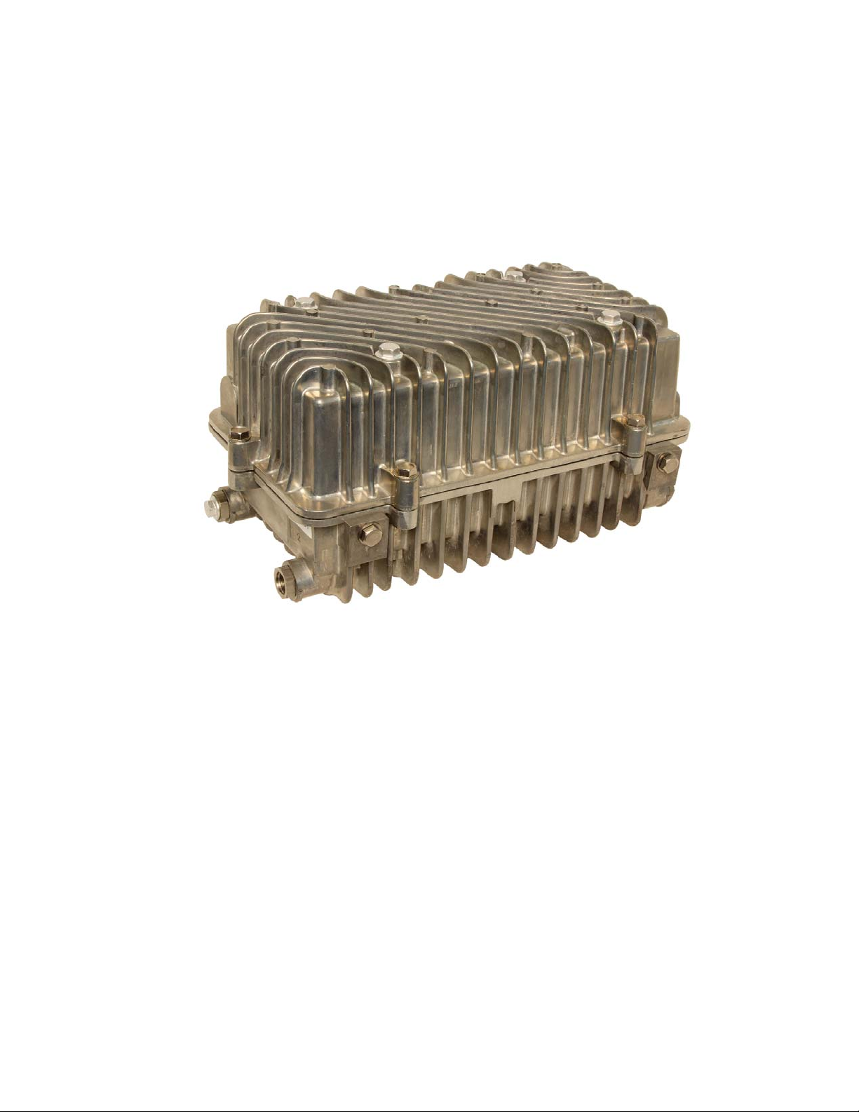
1.1 Introduction
The Alpha Power Booster (APB) was created to improve network effi ciency and reduce life
cycle cost by eliminating lightly loaded power supplies at the end of long amplifi er cascades.
The voltage booster accomplishes this by boosting end-of-line voltages. The voltage boost
allows deeper penetration of the HFC network and eliminates the need for power supplies
and batteries near the end of the HFC network.
016-559-B0-001 Rev. A
Fig. 1-1, APB Voltage Booster
7
Page 8
1.0 System Overview, continued
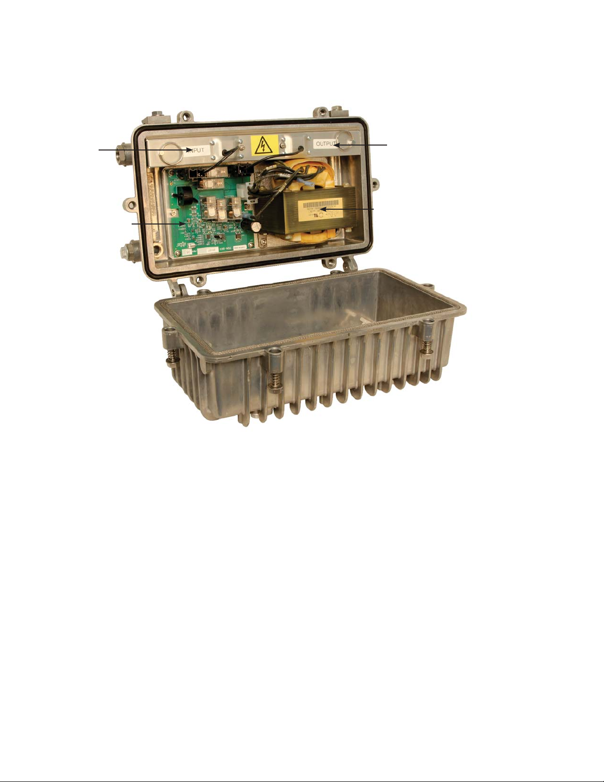
1.2 Internal Components
Input
Tap-switch PCBA
RF Module with
Input and Output Connectors
Output
Step-up Autotransformer
Fig. 1-2, APB Internal Components
8
016-559-B0-001 Rev. A
Page 9

2.0 Installation
2.1 Enclosure Installation
2.1.1 Strand Mounting
Tools Required:
• 1/2” Socket
• 0-100 in-lb torque wrench
Procedure:
1. Loosen the two strand clamps on the enclosure. Ensure that the side labeled "INPUT" is facing the
correct direction.
2. Place the strand wire under the clamp plates and torque the bolts to 75 in-lbs.
3. Ensure that the output voltage is confi gured properly. Refer to section 2.2 if the output voltage requires
changing.
4. Prepare the coaxial connector(s) as outlined in Section 2.3, "Cable Preparation". Install the
connector(s) and tighten to proper torque supplied by the manufacturer.
Strand Wire
Side View
Strand Clamps Strand Clamps
Top View
016-559-B0-001 Rev. A
9
Page 10

2.0 Installation, continued
2.1 Enclosure Installation, continued
2.1.2 Surface Mounting
Tools Required:
• 1/2” Socket
• 0-100 in-lb torque wrench
• Drill
• 3/8” drill bit
Procedure:
1. Loosen the two strand clamps on the enclosure. Ensure that the side labeled "INPUT" is
facing the correct direction.
2. Verify that the mounting surface is fl at between the mounting locations prior to drilling.
3. Drill two 3/8” holes that are 10” apart.
4. The threaded holes in the enclosure are 1/2” deep. Verify the bolts extend no more than 3/8”
through the mounting surface. Use 5/16-18 threaded bolts.
5. Tighten the mounting bolts to 90 in-lbs.
6. Tighten the coaxial connector(s) to proper torque provided by the manufacturer.
Mounting Surface
Mounting
Holes
5/16"-18
Mounting
Bolts
10
016-559-B0-001 Rev. A
Page 11

2.0 Installation, continued
2.2 Output Voltage Confi guration
Tools Required:
• True RMS Volt Meter
• Clamp-On Amp Meter
1. Note the factory confi gured output voltage by reading the label on the side of the housing. The
label has a fi eld named FACTORY CONFIG that will be fi lled with either 63Vac or 87Vac.
Fig. 2-1, Label with Factory Confi g Field
2. If the factory confi guration must be changed, unplug the quick connects and attach the connector
labelled LOG87 (for 90V plant) or LOG63 (for 60V plant) to the “Confi guration” male quick
connect. The unused wire should be attached to P4 to prevent arcing to the power supply
housing.
016-559-B0-001 Rev. A
Fig. 2-2, Confi guration Connect
11
Page 12

2.0 Installation, continued
2.3 Cable Preparation
Tools Required:
• Wire Cutters
• Open-End wrenches (refer to manufacturer’s assembly instructions)
WARNING!
Coaxial cables may carry AC power. To avoid possible shock or damage to the
equipment, always handle coaxial cables with extreme caution. Always install coaxial
connectors with the RF module removed from the enclosure.
NOTE:
This section is for reference only; follow instructions provided by the connector’s manufacturer.
Procedure:
1. Assemble coaxial connectors with no more than 13 inches between ends.
2. Cut the pin length as shown on the following page.
1-7/16"
to
1-5/8"
Fig. 2-3, Coaxial Cable Connector
12
016-559-B0-001 Rev. A
Page 13

2.0 Installation, continued
2.3 Cable Preparation, continued
Installation is complete. Go to Power Up and Test (Section 2.7, Power Up and Test).
3. Locate the measuring gauge near port number 1 or 2.
4. Place the connector’s collar against the edge of the
measuring gauge molded into the enclosure.
5. Using heavy duty wire cutters, clip the pin as close to the
016-559-B0-001 Rev. A
line as possible.
13
Page 14

2.0 Installation, continued
2.4 RF Module Removal
Tools Required:
• No. 2 Flat head screwdriver
Procedure:
1. Disconnect the two Molex connectors (Output, J4, Input, J5).
2. Loosen the two captive screws near the center of the module.
3. Grasp the pull rings with your index fi ngers and pull fi rmly away from the enclosure.
Pull Ring
Disconnect per step 1
Captive Screws
Pull Ring
14
Disconnect per step 1
Fig. 2-4, RF Module Removal
Fig. 2-5, RF Module Removed
016-559-B0-001 Rev. A
Page 15

2.0 Installation, continued
2.5 Coaxial Cable Attachment
Tools Required:
• 5/8” socket wrench with 6” extension
• 20-200 in-lb torque wrench
Procedure:
1. Remove the two seizure connectors from
the enclosure.
NOTE:
Verify center conductor is centered in the groove in
the plastic base.
2. Insert the prepared coaxial connector into
the desired port (1-input; 2-output) and
torque to 180 in-lbs.
3. Replace the seizure connectors and
torque to 90 in-lbs.
Fig. 2-6, Seizure Connector
Fig. 2-7, Visible Center Conductor of Installed
Connector
016-559-B0-001 Rev. A
15
Page 16

2.0 Installation, continued
2.6 RF Module Reinstallation
Tools Required:
• No. 2. Flat head screwdriver
• Torque screwdriver
Procedure:
1. Firmly seat the module over the seizure connectors, with the open side facing AWAY from
the circuit board.
2. Tighten the captive screws to 18 in-lbs.
WARNING!
The enclosure may become electrifi ed if mis-wired or in the event of an internal short.
Measure the voltage between the enclosure and earth ground before touching with bare
hands.
3. Connect the Molex connectors (Output, J4, Input, J5). Ensure that the output connector is
plugged into J4 and the input connector is plugged into J5.
Reconnect per step 3
Fig. 2-8, RF Module Installation
Captive Screws
Reconnect per step 3
16
016-559-B0-001 Rev. A
Page 17

2.0 Installation, continued
2.7 Power Up and Test
2.7.1 Initial Power Up
Tools Required:
• True RMS Volt Meter
• Clamp-On Amp Meter
WARNING!
There will be up to 90Vac present on the PCB when a live connector is plugged into the
input or output connectors.
Procedure:
1. Plug the Output Connector from the RF Module
into the J4 Output Connector (item 1) of the PCB.
2. Plug the Input Connector from the RF Module into
the J5 Input Connector (item 2) of the PCB. Verify
the GREEN LED (item 3) on PCB is lit.
3. Using the volt meter, measure the output voltage
between TP13 and the enclosure chassis. The
voltage should be approximately 87Vac for the
87Vac confi guration or 63Vac for the 63Vac
confi guration.
3
TP13
2
1
016-559-B0-001 Rev. A
4. Place a Clamp-on amp meter over the output wire
coming from the Output connector J4 on the PCB
and the RF Module. The current must be less than
8A RMS. If the current exceeds 8A RMS, resolve
the cause of the short-circuit or overload condition.
17
Page 18

2.0 Installation, continued
2.8 Final Assembly
Tools Required:
• 1/2” Socket
• 0-100 in-lb torque wrench
Procedure:
1. Close the cover of the enclosure, making sure no wires are being pinched. Tighten all bolts
fi nger tight.
2. Tighten the enclosure cover bolts to 30 in-lbs, in the sequence shown. Repeat the procedure,
tightening the bolts to 70 in-lbs.
6
4
2
1
3
18
5
Fig. 2-9, Cover Bolts
016-559-B0-001 Rev. A
Page 19

2.0 Installation, continued
2.9 Specifi cations
Specifi cations
Electrical
Input Voltage 45-65Vac 60Hz / 65-90Vac 60 Hz
Input Current 10 Amps RMS (max)
Output Voltage 63Vac 60Hz / 87Vac 60Hz
Output Current <8 Amps RMS (max)
Output Rating 650 VA (max)
Overload Protections 115% for 27 minutes
Short Circuit Bypass mode, automatic recovery
Overload Recovery Automatic
Surge Resistance 6kV/3000A (IEEE C61.45 part 15)
Effi ciency >96% at 25 to 100 percent load
RF Freq Range 5MHz to 1000MHz
RF Insertion Loss
Maximum
Flatness ±0.25 dB (5MHz to 50MHz)
RF Slope Maximum 0.80dB (5MHz to 50MHz)
Hum Modulation
Return Loss Minimum 17 dB (5MHz to 1000MHz)
Electrical Egress <-120dBm (45MHz to 870MHz)
Isolation Neutral carries through
Environmental
Operating Temperature -40°F to 149°F (-40°C to 65°C)
Storage Temperature -58°F to 158°F (-50°C to 70°C)
Outdoor Rating Type 4 Enclosure
Standard Compliance
Safety CSA (C/US)
Standard Features
High-effi ciency autotransformer
Intelligent overload protection
Water-tight enclosure; wall or strand mounted
1.2 dB (5MHz to 50MHz)
1.2 dB (50MHz to 870MHz)
1.6 dB (870MHz to 1000MHz)
±0.35 dB (50MHz to 870MHz)
±0.50 dB (870MHz to 1000MHz)
-1.0dB (50MHz to 870MHz), -1.25dB (870MHz to 1000MHz)
< -68 dB (5MHz to 1000MHz)(< -82 dB freq. domain)
CAN/CSA C22.2 No. 60950-1-07
UL 60950-1, 2nd Edition
016-559-B0-001 Rev. A
19
Page 20

2.0 Installation, continued
2.10 Troubleshooting
Troubleshooting Guide
Symptom Probable Cause and Solution
No Output No Input Voltage
63Vac Confi g: Verify that no less than 45Vac is present on
the input connector.
87Vac Confi g: Verify that no less than 65Vac is present on
the input connector.
RF Module Not Fully Seated
Ensure the RF Module is fully seated and the captive screws
are tight. Module should be fl ush with the rim of the lower
half of the enclosure. Check connections from RF Module to
power supply.
PCBA Connectors Not Fully Seated
Ensure the RF Module connectors are fully seated to the
PCBA at J4 & J5, and that the transformer connector is fully
seated at J1.
Overload Relay Open
If the unit is overloaded it will open a relay to protect vital
components and cease output. A solid green LED will light up
on the PCBA if the unit is functional, but overloaded. In this
situation the unit must be repositioned in the network where
the input current is less than 10A.
Output Voltage Low Input Voltage Below 45/65Vac
Inspect input connections and upstream power supplies,
verify no less than 45Vac (63Vac Confi g) or 65Vac (87Vac
Confi g) is present at the input port (measure voltage from
TP14 to the enclosure).
Input and Output Coax Connectors Reversed
Verify the Coax Input Connector is connected to Port 1.
Output Voltage High Input Voltage Above 63/90Vac
Inspect input connections and upstream power supplies,
verify no greater than 63Vac (63Vac Confi g) or 90Vac (87Vac
Confi g) is present at the input port (measure voltage from
TP14 to the enclosure).
20
Table 2-1, Troubleshooting Guide
016-559-B0-001 Rev. A
Page 21

2.0 Installation, continued
2.11 Voltage Booster Service
Tools Required:
• No. 2 Phillips head screwdriver
WARNING!
There will be up to 90Vac present on the PCB when a live connector is plugged into the
input or output connectors.
2.11.1 PCB Replacement Procedure
1. Unplug Input Connector from J5 of the PCB.
2. Unplug Output Connector from J4 of the PCB.
3. Unplug XFMR Connector from J1 of the PCB.
4. Loosen captive bracket screws at "4" (2 places).
5. Remove assembly.
6. Install new assembly and tighten the captive bracket screws at "4" (2 places).
7. Plug XFMR Connector into J1 of the PCB.
8. Plug Output Connector into J4 of the PCB.
9. Plug Input Connector into J5 of the PCB.
10. Perform power up test (section 2.7.1), and fi nal assembly (section 2.8).
2
1
4
2
3
4
016-559-B0-001 Rev. A
21
Page 22

2.0 Installation, continued
2.11 Voltage Booster Service, continued
Tools Required:
• 11/32 Nutdriver
WARNING!
There will be up to 90Vac present on the PCB when a live connector is plugged into the
input or output connectors.
2.11.2 Transformer Replacement Procedure
1. Unplug transformer connector from J1 of the PCB.
2. Unplug transformer quick connects from Confi guration (P1) and P4 of the PCB. Note which
connector is attached to the Confi guration male connector (LOG63 or LOG87).
3. Remove nuts at "3" (4 places).
4. Remove transformer.
5. Install new transformer with nuts at "3" (4 places).
6. Plug the connector from step 2 into the Confi guration male connector (P1). Plug the other
unused connector into P4.
7. Plug the transformer connector into J1 of the PCB.
3
1
2
3 3
3
22
016-559-B0-001 Rev. A
Page 23

this page intentionally blank
Page 24

Alpha Technologies Inc.
3767 Alpha Way
Bellingham, WA 98226
United States
Tel: +1 360 647 2360
Fax: +1 360 671 4936
Alpha Technologies Ltd.
7700 Riverfront Gate
Burnaby, BC V5J 5M4
Canada
Tel: +1 604 436 5900
Fax: +1 604 436 1233
Toll Free: +1 800 667 8743
Alpha Industrial Power Inc.
1075 Satellite Blvd NW,
Suite 400
Suwanee, GA 30024
United States
Tel: +1 678 475 3995
Fax: +1 678 584 9259
Alpha Energy
1628 W Williams Drive
Phoenix, AZ 85027
United States
Tel: +1 623 251 3000
Fax: +1 623 249 7833
Alpha Technologies Europe Ltd.
Twyford House Thorley
Bishop’s Stortford
Hertfordshire, CM22 7PA
United Kingdom
Tel: +44 1279 501110
Fax: +44 1279 659870
Alpha Technologies
Unit 504, 5/F,
Fourseas Building
No 208-212 Nathan Road
Kowloon, Hong Kong
Tel: +852 2736 8663
Fax: +852 2199 7988
Alpha Technologies GmbH
Hansastrasse 8
D-91126
Schwabach, Germany
Tel: +49 9122 79889 0
Fax: +49 9122 79889 21
Alphatec Ltd.
339 St. Andrews St.
Suite 101 Andrea Chambers
P.O. Box 56468
3307 Limassol, Cyprus
Tel: +357 25 375 675
Fax: +357 25 359 595
Alpha Innovations Brasil
Avenida Ibirapuera,
2120 – Cj 76
Moema - 04028-001
Santos SP, Brazil
Tel: +55 11 2476 0150
Fax: +55 11 2476 0150
T echnologies Argus
First de Mexico
Anatole France Num. 17
Colonia Polanco
11560, México D.F.
Tel: +52 55 5280 6990
Alpha TEK ooo
Khokhlovskiy Pereulok 16
Stroenie 1, Offi ce 403
Moscow, 109028
Russia
Tel: +7 495 916 1854
Fax: +7 495 916 1349
Alphatec Baltic
S. Konarskio Street 49-201
Vilnius, LT-03123
Lithuania
Tel: +370 5 210 5291
Fax: +370 5 210 5292
Visit us at www.alpha.com
Due to continuing product development, Alpha Technologies reserves the right to change specifi cations without notice.
Copyright © 2011 Alpha Technologies. All Rights Reserved. Alpha
®
is a registered trademark of Alpha Technologies. 016-559-B0-001 Rev. A
 Loading...