

Page 1
Alpha Modular Power System 24 HP
Installation & Operation Manual
Part # 0260011-J0
Effective: 03/2012
member of The Group
™
Your Power Solutions Partner
Page 2

Page 3

Alpha Modular Power System 24 HP
Installation & Operation Manual
NOTE:
Photographs contained in this manual are for illustrative purposes only. These photographs
may not match your installation.
NOTE:
Operator is cautioned to review the drawings and illustrations contained in this manual
before proceeding. If there are questions regarding the safe operation of this powering system, contact Alpha Technologies or your nearest Alpha representative.
NOTE:
Alpha shall not be held liable for any damage or injury involving its enclosures, power supplies, generators, batteries, or other hardware if used or operated in any manner or subject
to any condition not consistent with its intended purpose, or is installed or operated in an
unapproved manner, or improperly maintained.
For technical support, contact Alpha Technologies:
Copyright
Copyright © 2012 Alpha Technologies Ltd. All rights reserved. Alpha is a registered trademark of
Alpha Technologies.
No part of this documentation shall be reproduced, stored in a retrieval system, translated,
transcribed, or transmitted in any form or by any means manual, electric, electronic,
electromechanical, chemical, optical, or otherwise without prior explicit written permission from
Alpha Technologies.
This documentation, the software it describes, and the information and know-how they contain
constitute the proprietary, confidential and valuable trade secret information of Alpha Technologies,
and may not be used for any unauthorized purpose, or disclosed to others without the prior written
permission of Alpha Technologies.
The material contained in this document is for information only and is subject to change without
notice. While reasonable efforts have been made in the preparation of this document to assure
its accuracy, Alpha Technologies assumes no liability resulting from errors or omissions in this
document, or from the use of the information contained herein. Alpha Technologies reserves the right
to make changes in the product design without reservation and without notification to its users.
Canada and USA: 1-888-462-7487
International: +1-604-436-5547
Email: support@alpha.ca
Page 4

Table of Contents
1. Safety .............................................................................................................................. 6
1.1 Safety Symbols ............................................................................................................................. 6
1.2 General Safety .............................................................................................................................. 7
1.3 External Battery Safety ................................................................................................................. 8
1.4 Utility Power Connection ............................................................................................................... 8
1.5 Equipment Grounding ................................................................................................................... 9
2. Product Description....................................................................................................... 10
2.1 Theory of Operation .................................................................................................................... 10
2.2 System Components ................................................................................................................... 12
2.3 Rear Components ....................................................................................................................... 13
2.4 Low Voltage Battery Disconnect (Optional) ................................................................................ 15
2.5 Battery Temperature Probes ....................................................................................................... 16
2.6 Network Requirements ............................................................................................................... 17
3. Power Congurations.................................................................................................... 19
3.1 Power System Conguration Terminology .................................................................................. 19
3.2 4i Shelf Systems (No Battery Charger) ....................................................................................... 20
3.3 3i+1R Shelf Systems (Integrated Battery Charger) .................................................................... 20
3.4 System Spares ............................................................................................................................ 20
3.5 120V Single Phase Systems ....................................................................................................... 21
3.6 120V/240V Split Phase or 120/208V 2-Pole Systems ................................................................ 24
3.7 120V/208V 3-Phase Systems ..................................................................................................... 27
3.8 AMPS24 HP - Recommended DC Breaker and Wire Sizes ....................................................... 29
3.9 How to Congure Inverters in AC Input Groups, AC Output Groups and DC Input Groups ....... 30
4. System Pre-Installation ................................................................................................. 32
4.1 Site Selection .............................................................................................................................. 32
4.2 Recommended Installation Layout .............................................................................................. 32
4.3 Transporting the Cabinet ............................................................................................................. 33
4.4 Unpacking Instructions ................................................................................................................ 34
5. Installation ..................................................................................................................... 35
5.1 Input/Output Cabling ................................................................................................................... 35
5.2 AC Wiring .................................................................................................................................... 37
2
Doc. #: 0260011-J0 Rev B
Page 5

5.3 DC Battery and Ground Cabling ................................................................................................. 38
5.4 DC Ground .................................................................................................................................. 41
5.5 AMPS24 HP with External Maintenance Bypass Switch ............................................................ 42
5.6 Generator Automatic Transfer Switch ......................................................................................... 42
5.7 Commissioning the System for the First Time ............................................................................ 43
6. System Operation ......................................................................................................... 52
6.1 CXCU Controller Operation ........................................................................................................ 52
6.2 Inverter monitoring and control ................................................................................................... 55
6.3 Inverter Module Indicators .......................................................................................................... 62
6.4 Rectier Module .......................................................................................................................... 63
7. Preventive Maintenance ............................................................................................... 67
7.1 Recommended maintenance schedule ....................................................................................... 67
7.2 Tools and Equipment .................................................................................................................. 67
7.3 Spare Parts ................................................................................................................................. 68
7.4 Replacing a Rectier ................................................................................................................... 69
7.5 Replacing a Defective Fan—Inverter or Rectier ........................................................................ 69
7.6 Removing the CXCU Controller .................................................................................................. 69
7.7 Replacing the Surge Suppression Module .................................................................................. 70
7.8 Fuse Replacement ...................................................................................................................... 71
7.9 Synchronization with a Maintenance Bypass Switch (MBS) ....................................................... 73
8. Troubleshooting ............................................................................................................ 74
8.1 Non Recoverable Error ............................................................................................................... 74
8.2 Recoverable Error ....................................................................................................................... 74
9. System Specications ................................................................................................... 84
9.1 Power De-rating Due To Altitude ................................................................................................. 84
9.2 Power De-rating Due To Temperature ........................................................................................ 84
9.3 System Specications ................................................................................................................. 85
9.4 Specications for AIM 1500 Module ............................................................................................ 86
9.5 Specications for 48-1.8 kW Rectier (P/N 010-621-20-040) ..................................................... 87
10. Conguration Parameters ........................................................................................... 88
10.1 Transferring Inverter Settings to Another System ..................................................................... 88
10.2 Examples of Modications to Conguration Parameters .......................................................... 88
10.3 Global Settings (ID 1 – 50) ........................................................................................................ 90
Doc. #: 0260011-J0 Rev B
3
Page 6

10.4 Inverter Parameters (ID 51 – 550) ............................................................................................ 91
10.5 Alarm Settings (ID 551-950) ...................................................................................................... 97
11. Warranty ...................................................................................................................... 99
11.1 Battery Warranty ....................................................................................................................... 99
12. Certication ............................................................................................................... 100
List of Figures
Figure 1 — AMPS24 HP System Components .................................................................................. 13
Figure 2 — Surge Suppression Modules ........................................................................................... 14
Figure 3 — AMPS24 HP rear view (with protective covers removed) ................................................ 14
Figure 4 — Eight-pin terminal strip and 40-pin connector pin locations ............................................. 15
Figure 5 — LVD wiring ....................................................................................................................... 16
Figure 7 — Batteries > Congure Batteries ....................................................................................... 17
Figure 6 — Battery temperature probes ............................................................................................ 17
Figure 8 — Cable connection to CXCU for graphic display ............................................................... 18
Figure 9 — Single network connection to CXCU ............................................................................... 18
Figure 10 — Multiple network connections to the CXCU ................................................................... 19
Figure 11 — Split Phase from a Single phase supply ........................................................................ 20
Figure 12 — 2-Pole from a 3-phase supply ...................................................................................... 20
Figure 13 — Monitoring AC Input Groups, AC Output Groups and DC Input Groups ....................... 31
Figure 14 — DC input breakers ......................................................................................................... 32
Figure 15 — Shipping dimensions (in inches) ................................................................................... 34
Figure 16 — AMPS24 Power and Battery Connections ..................................................................... 37
Figure 17 — AC Wiring connections diagram .................................................................................... 38
Figure 18 — AC Wiring (shown for 3-phase) ..................................................................................... 38
Figure 19 — Single feed, parallel battery strings ............................................................................... 39
Figure 20 — Dual feed, two battery strings in parallel ....................................................................... 40
Figure 21 — DC battery wiring with independent dual A/B feed ........................................................ 41
Figure 22 — DC ground, inverter only systems ................................................................................. 42
Figure 23 — Representative system wiring for AMPS24 HP system with MBS ................................ 43
Figure 24 — Controller ....................................................................................................................... 45
4
Doc. #: 0260011-J0 Rev B
Page 7

Figure 25 — Controller default home screen ..................................................................................... 45
Figure 26 — Placement of initial inverters (shown for split phase system) ........................................ 46
Figure 27 — Inverter module showing AC input LED ........................................................................ 46
Figure 28 — Unlocking and locking an inverter module for removal or insertion ............................... 47
Figure 29 — Inserting and removing an inverter module ................................................................... 47
Figure 30 — Inverters > View Live Status.......................................................................................... 48
Figure 31 — Matching AC Input Groups to AC Output Groups ......................................................... 49
Figure 32 — Set Output (Split Phase System) .................................................................................. 50
Figure 33 — Inserting blanks in open slots ........................................................................................ 51
Figure 34 — CXCU system controller home screen .......................................................................... 53
Figure 35 — CXCU controller ............................................................................................................ 54
Figure 36 — Editing the user interface text. ....................................................................................... 55
Figure 37 — Inverters > View Live Status interface ........................................................................... 56
Figure 38 — Set Output window ........................................................................................................ 57
Figure 39 — Group Mapping window (shown for a two phase system) ............................................. 58
Figure 40 — Group Status window .................................................................................................... 58
Figure 41 — Set Input window .......................................................................................................... 59
Figure 42 — General Settings window .............................................................................................. 59
Figure 43 — Congure alarms window ............................................................................................. 60
Figure 44 — T2S alarms in event logs ............................................................................................... 61
Figure 45 — Retrieve alarm history le .............................................................................................. 61
Figure 46 — Signals (inverters) window ........................................................................................... 62
Figure 47 — Auto DC Priority ............................................................................................................. 62
Figure 48 — Inverter module status, power LEDs ............................................................................. 63
Figure 49 — Output power indicator LEDs ........................................................................................ 63
Figure 50 — Cordex 48-1.8kW .......................................................................................................... 64
Figure 51 — Surge Suppression Modules ......................................................................................... 71
Figure 52 — Rectier fuses (behind back top panel) ......................................................................... 72
Figure 53 — Fuse location for LCD touch screen .............................................................................. 73
Figure 54 — Maintenance Bypass Switch ......................................................................................... 74
Figure 55 — Manage Cong File window .......................................................................................... 89
Doc. #: 0260011-J0 Rev B
5
Page 8

List of Tables
Table A — Eight-pin Terminal Strip from AMPS 24 ............................................................................ 15
Table B — Pinouts for 40 Pin Connector Interface to CXCR ............................................................. 16
Table C — 10.5kVA, 9kVA and 4.5kVA, 120V Single Phase 3i+1R Shelf Systems ........................... 23
Table D — 12kVA and 6kVA, 120V Single Phase, 4i Shelf Systems ................................................. 24
Table E — 21kVA, 18kVA, & 9.0kVA 120/240V Split Phase or 120/208 2-Pole 3i+1R Shelf ............. 26
Table F — 24kVA & 12KVA 120/240V Split Phase or 120/208 2-Pole 4i shelf Systems .................... 27
Table G — 18kVA and 13.5kVA, 120V/208V 3-Phase Systems ........................................................ 29
Table H — DC Input Groups .............................................................................................................. 32
Table I — Tools .................................................................................................................................. 68
Table J — Spare Parts ....................................................................................................................... 69
Table K — Inverter Alarm Codes ........................................................................................................ 78
6
Doc. #: 0260011-J0 Rev B
Page 9
1. Safety
SAVE THESE INSTRUCTIONS: This manual contains important safety
instructions that must be followed during the installation, servicing, and maintenance of the product.
Keep it in a safe place. Review the drawings and illustrations contained in this manual before proceeding.
If there are any questions regarding the safe installation or operation of this product, contact Alpha
Technologies or the nearest Alpha representative. Save this document for future reference.
1.1 Safety Symbols
To reduce the risk of injury or death, and to ensure the continued safe operation of this product, the
following symbols have been placed throughout this manual. Where these symbols appear, use extra
care and attention.
The use of ATTENTION indicates specic regulatory/code requirements that may affect the
placement of equipment and /or installation procedures.
NOTE:
A NOTE provides additional information to help complete a specic task or procedure. Notes
are designated with a checkmark, the word NOTE, and a rule beneath which the information
appears.
CAUTION!
CAUTION indicates safety information intended to PREVENT DAMAGE to material or equipment. Cautions are designated with a yellow warning triangle, the word CAUTION, and a rule
beneath which the information appears.
WARNING!
WARNING presents safety information to PREVENT INJURY OR DEATH to personnel. Warnings are indicated by a shock hazard icon, the word WARNING, and a rule beneath which the
information appears.
HOT!
The use of HOT presents safety information to PREVENT BURNS to the technician or user.
Doc. #: 0260011-J0 Rev B
7
Page 10

1.2 General Safety
• Only qualified personnel shall install, operate, and service the power system and components.
• Observe all applicable national and local electrical and building codes during installation.
• Mount the AMPS24 HP system in a rack that is securely bolted to the floor.
• Always assume electrical connections and/or conductors are live.
• Turn off all circuit breakers and double-check potentially charged components with a voltmeter
before performing installation or maintenance.
• Before installation, verify that the input voltage and current requirements of the load are within
the specifications of the power system. Refer to the product nameplate label.
• Keep tools away from walk areas to prevent personnel from tripping over the tools.
• Wear safety glasses when working under any conditions that may be hazardous to your eyes.
• Do not work on the power system, or connect or disconnect cables, during atmospheric lightning
activity.
• Do not let water enter the enclosure as this can cause electrical shorts, shocks, or electrocutions.
• Do not remove the covers of electrical components as this can cause electrical shorts, shocks or
electrocutions. There are no user serviceable parts inside.
• The power system is certified for use in restricted access locations only.
• All operators must be trained to perform the emergency shutdown procedure.
• For 3i+1R shelf models containing rectifiers, see section 7.8 to replace internal fuses.
• The power system must be connected only to a dedicated branch circuit.
• Equip the utility service panel with a circuit breaker of appropriate rating.
• Do not exceed the output rating of the system when connecting the load.
• External metal surface temperatures on the rear of the AMPS24 HP system can exceed 70°C.
Use caution when working around the equipment while it is in operation.
• Always use proper lifting techniques when handling units, modules, or batteries.
• The power system contains more than one live circuit. Voltage may still be present at the output
even when the input voltage is disconnected.
• Minimize the risk of sparks and wear on the connectors. Always switch off the inverter’s battery
circuit breaker before connecting or disconnecting the battery pack.
• In the event of a short-circuit, batteries present a risk of electrical shock and burns from high
currents. Observe proper safety precautions.
• Always wear protective clothing, such as insulated gloves, and safety glasses or a face shield
when working with batteries.
• Carry a supply of water, such as a water jug, to wash eyes or skin in case of exposure to battery
electrolyte.
• Do not allow live battery wires to contact the enclosure chassis. Shorting battery wires can result
in a fire or possible explosion.
• Replace batteries with those of an identical type and rating. Never install old or untested batteries.
• Only use insulated tools when handling batteries or working inside the enclosure.
• Remove all rings, watches and other jewelry before servicing batteries.
• Recycle used batteries. Spent or damaged batteries are environmentally unsafe. Refer to local
codes for the proper disposal of batteries.
8
Doc. #: 0260011-J0 Rev B
Page 11

• A disconnect switch shall be provided by others for the AC input and AC output circuits.
• Risk of Electric Shock and Fire Hazard: replace fuse with the same type and rating.
1.3 External Battery Safety
• The power system requires an over-current protection device for the external batteries. The
maximum allowable current is typically 450A but can be less depending on the model. Follow
the local electrical codes.
• Ensure that the external battery connection is equipped with a disconnect.
• If the batteries are stored for extended periods before the installation, charge the batteries at
least once every three months to ensure optimum performance and maximum battery service
life.
• Refer to the battery manufacturer’s recommendation to select the correct float and equalize
charge voltage settings. Failure to do so can damage the batteries. Verify that the battery charger’s float and equalize settings are correct.
• The batteries are temperature sensitive. During extremely cold conditions, a battery’s charge
acceptance is reduced and requires a higher charge voltage. During extremely hot conditions,
a battery’s charge acceptance is increased and requires a lower charge voltage. To allow for
changes in temperature, the battery charger must be equipped with a temperature compensating system. For 3i+1R shelf systems, refer to the rectifier manual for information about temperature compensation.
• If the batteries appear to be overcharged or undercharged, first check for defective batteries
and then verify that the charger voltage settings are correct.
• To ensure optimal performance, inspect the batteries according to the battery manufacturers
recommendations. Check for signs of cracking, leaking, or unusual swelling. Some swelling is
normal.
• Check the battery terminals and connecting wires. Periodically clean the battery terminal con-
nectors and retighten them to the battery manufacturer's torque specifications. Spray the terminals with an approved battery terminal coating such as NCP-2 or No-Ox.
• Verify that the polarity of the cables are correct before connecting the batteries to the power
module. The polarity is clearly marked on the batteries. The battery breaker will trip and the rectifiers may be damaged if the cables are connected with the wrong polarity.
1.4 Utility Power Connection
Connecting to the utility must be performed by qualified service personnel only and must comply
with local electrical codes. The utility power connection must be approved by the local utility before
the installation.
Doc. #: 0260011-J0 Rev B
9
Page 12

1.5 Equipment Grounding
To provide a ready, reliable source of backup power, the power system must be connected to an
effective grounding and earthing system. The grounding system must be designed to protect both
personnel and equipment.
WARNING!
Low impedance grounding is mandatory for personnel safety, critical for the proper operation of the system, and must be in place and connected to the system before the supply
cables are connected.
1.5.1 Safety Ground
The safety ground is a two-part system – the utility service ground and the power system ground.
Utility Service Ground
As a minimum requirement for the protection of equipment, the local utility service must provide a
low-impedance path for fault current return to Earth. This must meet or exceed the requirements of
the US National Electrical Code or the Canadian Electrical Code.
Power System Ground
The power system ground consists of a low-impedance connection between the enclosure and an
Earth Ground, which must be located at least six feet away from the utility earth connection.
1.5.2 Lightning Strike Ground
Lightning strikes, grid switching, or other power surges on the power line and/or communications
cable can cause high-energy transients that can damage the power or communications systems.
Without a low-impedance path to the ground, the current will travel through wires of varying
impedance, which can produce damaging high voltages. The best method to protect the system
from damage is to divert these unwanted high-energy transients along a low-impedance path to the
ground.
See section "2.2 System Components" on page 13 for a description of the surge suppression modules
installed in the AMPS24 HP.
10
Doc. #: 0260011-J0 Rev B
Page 13
2. Product Description
The Alpha Modular Power System 24 HP (AMPS24 HP) is a unique, high performance AC power
system that is designed to provide highly reliable back-up power to cable headend, telecom or
server room facilities.
The AMPS24 HP features hot swappable 1.5 kVA/1.2 kW AC power modules and optional 1.8
kW rectifier modules that are the building blocks of a highly reliable power system with 99.999%
availability, 93% efficiency, and high power density. A smart, unified controller with an integrated
Ethernet/SNMP monitors and manages both AC power modules and rectifier modules through
a remote web-based GUI. The AMPS24 HP is designed for installation in a climate-controlled
environment where ambient temperatures are between 0°C to 50°C (32 to 122°F).
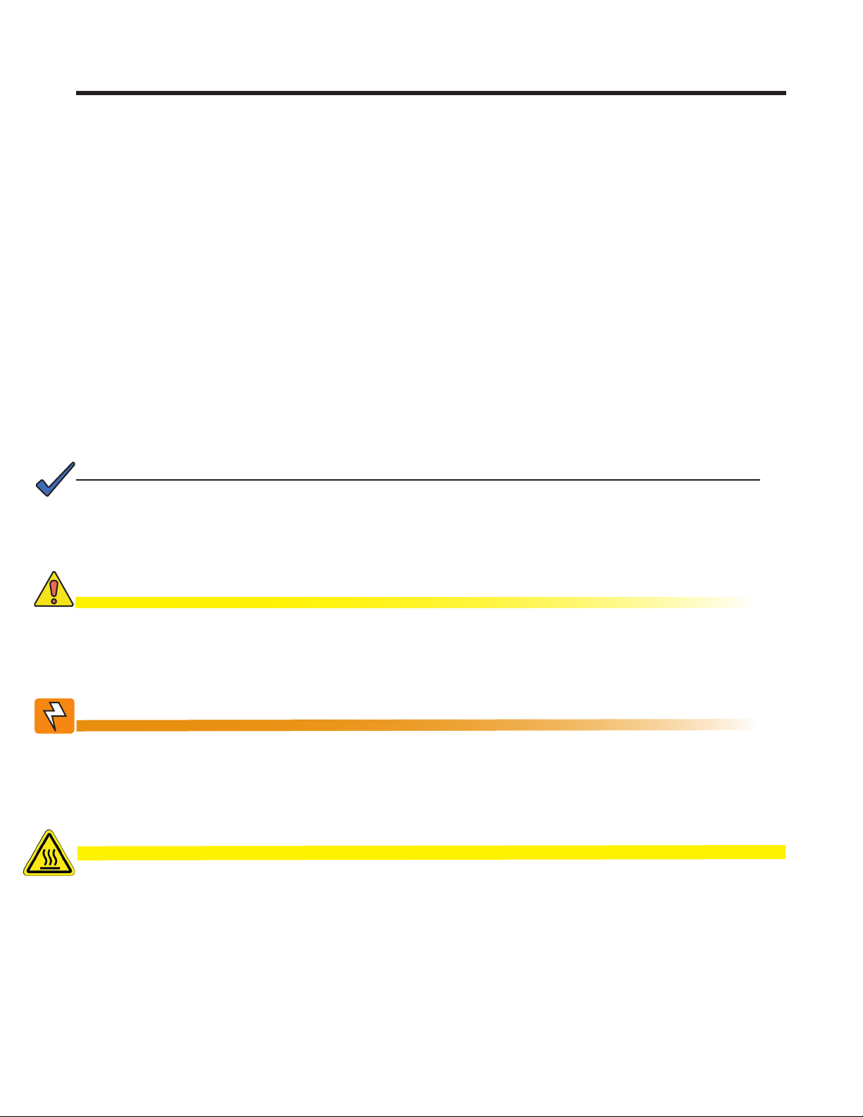
2.1 Theory of Operation
AMPS modules feature a revolutionary high performance technology that combines the high reliability
of a telecom-grade inverter system with the high efficiency of a UPS.
Each AMPS module includes a reliable 48VDC-to-120VAC inverter as well as an AC-to-DC rectifier.
When AC Mains is available, AC power is converted to a high voltage DC bus, which is then
converted back to AC. In this high performance (HP) mode, AMPS delivers fully conditioned, lineregulated telecom-grade AC power with 93% system efficiency.
AC
Mains
DC In
CAN bus external
communication
When AC Mains is unavailable, DC battery power is converted to AC with zero transfer time. An
intelligent high voltage DC bus decides when to draw power, and how much power to draw, from AC
or DC source. During AC input brownout condition, output power is supplemented by battery power.
In case of a fault, advanced DSP controls allow the AMPS module to isolate itself, while the rest of the
system continues to power the load (with reduced output).
DSP
Dual redundant
communication and
synchronization
between modules
Telecom Grade
AC Output
Doc. #: 0260011-J0 Rev B
11
Page 14
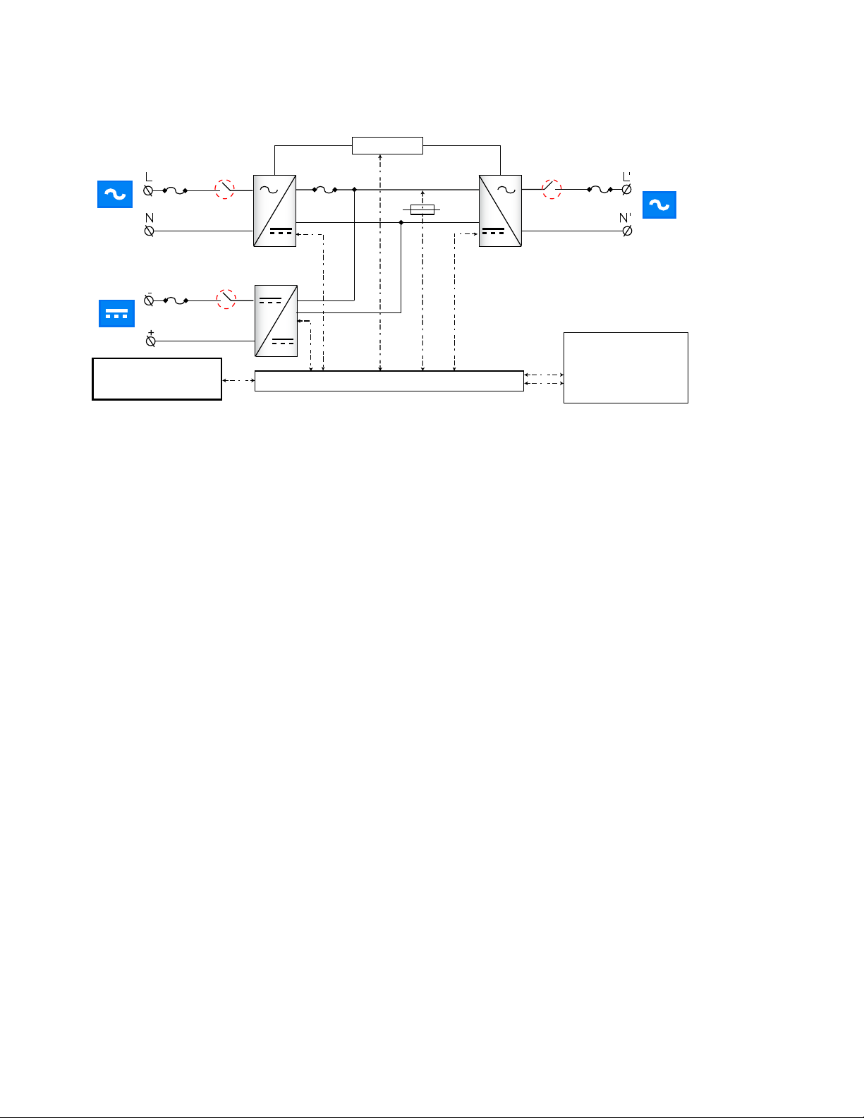
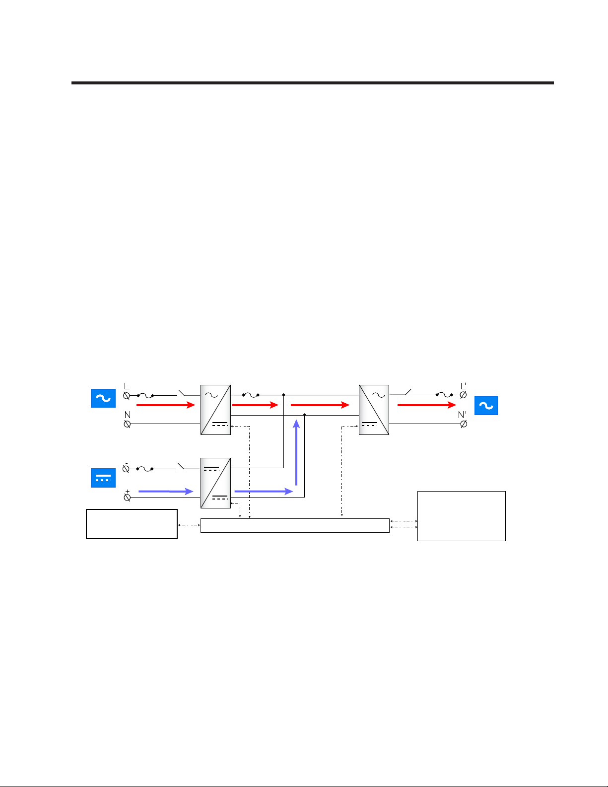
Boost
AC
Mains
DC In
CAN bus external
communication
AMPS modules also have a ‘Boost’ over-current feature with 10 times the rated current capacity
for 20ms, allowing it to trip breakers downstream, thus protecting the load.
2.1.1 AC or DC input priority
The user can choose either AC or DC input priority. If AC priority is chosen, the AMPS24 HP acts
more like an on-line, double conversion UPS. If AC commercial power is available, this power is
filtered twice and passed to the AC output. If the AC commercial power fails, the DC converter
simply takes over and supplies the power from the batteries.
DSP
400 Vdc
Telecom Grade
AC Output
Dual redundant
communication and
synchronization
between modules
12
If DC priority is chosen, AMPS24 HP acts more like an Inverter with AC bypass function.
Normally, power is drawn from the batteries. If DC power fails, the AC-DC converter takes over,
still providing regulated and filtered power to the load.
Doc. #: 0260011-J0 Rev B
Page 15
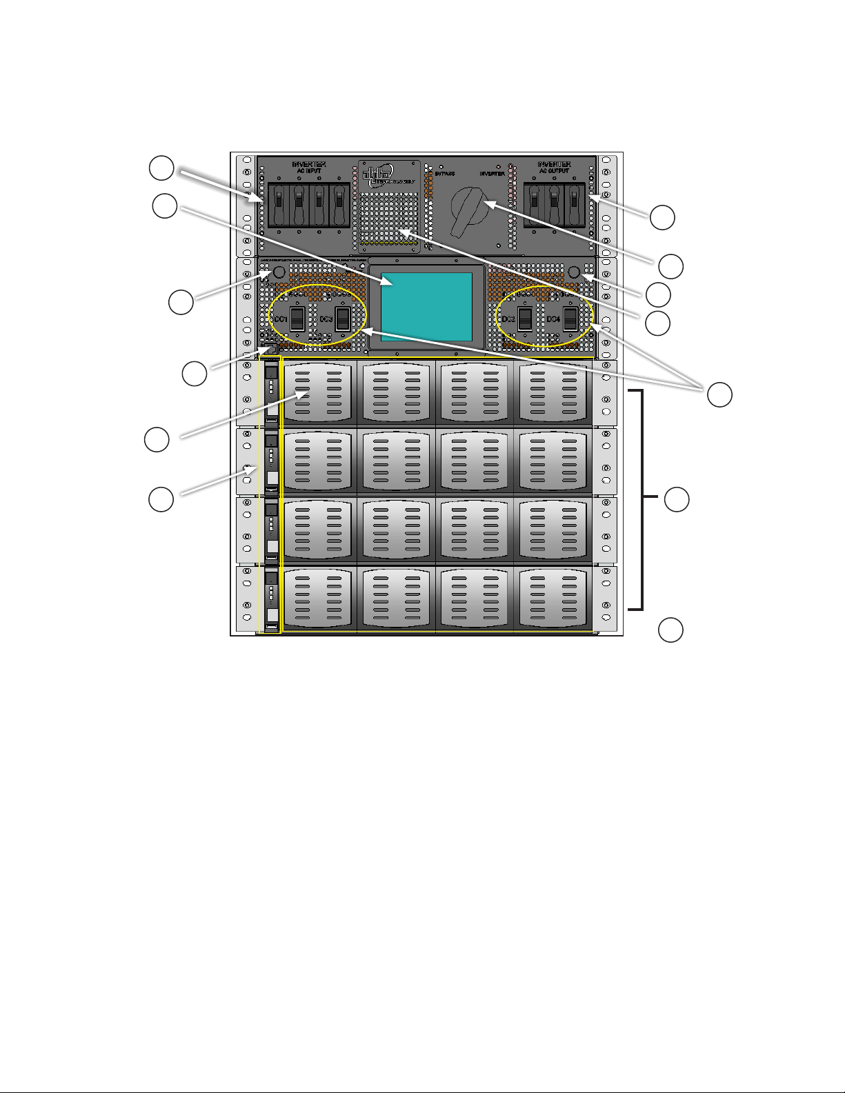
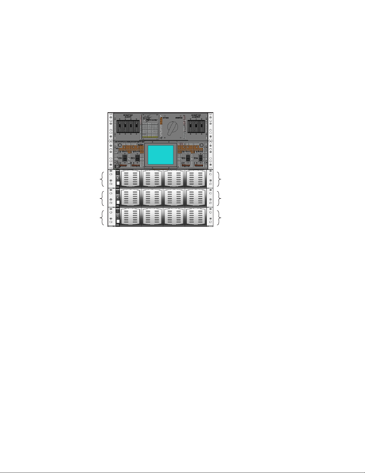
2.2 System Components
The AMPS24 HP is made up of a number of individual subsystems designed to work together to
provide highly reliable, filtered power in support of the load. A typical system contains the following:
1
10
4
11
5
6
3
2
12
13
7
8
9
Figure 1 — AMPS24 HP System Components
1. Inverter AC Input Breaker: Main disconnect for AC input
2. Internal Maintenance B ypass Switch (MBS) (optional): Can be used to route power directly
from the AC input to the AC output, bypassing the inverter modules.
3. Inverter AC Output Breaker: Serves as the main disconnect for the inverter AC outputs.
4. Graphic display touch screen: Connected to the CXCU controller by cable (see figure)
5. RJ45 cable connector: Front panel connection for cable from the CXCU to the Graphic display
6. CXCU Unified System Controller with integrated Ethernet / SNMP: Monitors and manages
both inverter and rectifier modules through a web-based GUI (only 1 per unit).
7. DC Input Breakers: Individual DC input breakers for each shelf.
8. 4i or 3i+1R shelves: Up to four shelves for installing up to four hot-swappable AIM 1500
modules OR three AIM 1500 modules plus one 1800W rectifier per shelf.
9. AIM 1500 Modules: Up to 4 AIM 1500 per 4i (4 x inverter modules) shelf or up to 3 AIM 1500
per 3i+1R (3 x inverter modules and 1 x rectifier module) shelf.
Doc. #: 0260011-J0 Rev B
13
Page 16
10. Rectifier Modules (opt ional): Up to one rectifier per
shelf. The rectifiers are used as the charging component
of a 3i+1R shelf system.
11. Fuse for the graphic display for the CXCU, and V+/ V- to
the controller
12. Fuse for customer use 2A load, pins #5 and #6 on 8-pin
terminal strip—see section 2.3.1 on page 15.
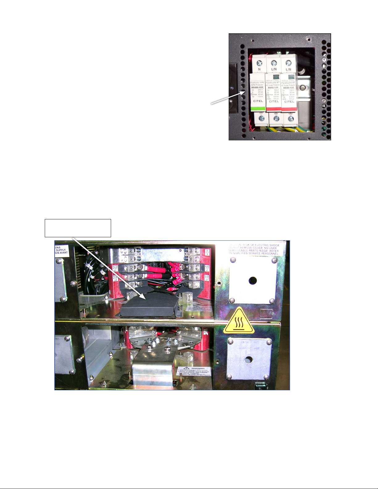
13. Surge Suppression Modules (behind removable
panel) built into the power distribution panel to protect
equipment from damage caused by surges and high
transient voltages. The surge suppression modules,
shown in Figure 2, short to ground any unwanted
voltages above a safe threshold.
2.3 Rear Components
AC and DC wiring are accessed from the rear of the unit. See Chapter 5 for details.
A 3i+1R shelf system (one rectifier and three AIM1500 modules) has AC rectifier fuses that protect
the system from a wiring fault. Remove the back cover of the AC Wiring panel to access the fuses.
Figure 2 — Surge Suppression Modules
Remove grey cover to
change rectier fuses
Figure 3 — AMPS24 HP rear view (with protective covers removed)
AC distribution
panel
DC distribution
panel
14
Doc. #: 0260011-J0 Rev B
Page 17
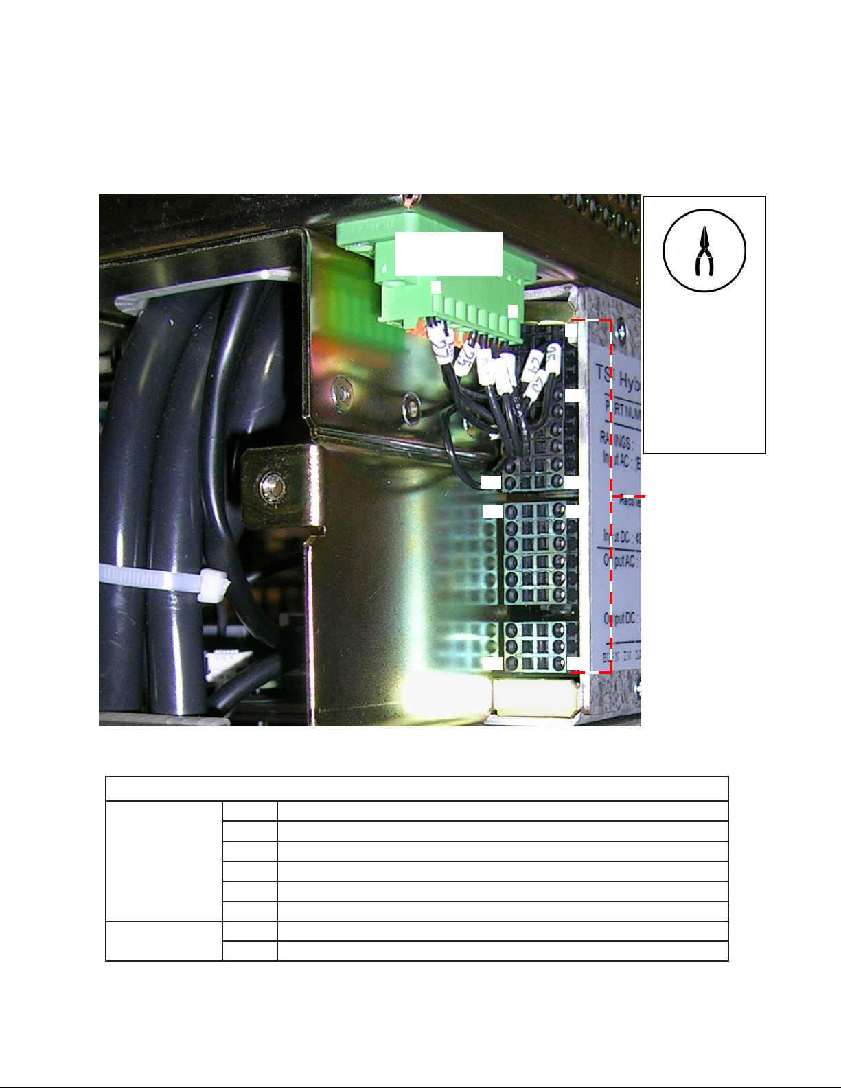
2.3.1 User Interface
On the side of the unit are two connectors. The eight-pin terminal strip is an interface to the AMPS24
with the pinouts listed in Table A. The 40-pin connector is an interface to the CXCR controller with the
pinouts listed in Table B. Some pins are available for customer use.
8-pin
terminal strip
8
19
21
39
1
2
10
20
22
To install wires
in the 40-pin
connector, use
needle-nose pliers
to remove the ter-
minal blocks in the
40-pin connector.
40 pin
connector
40
Figure 4 — Eight-pin terminal strip and 40-pin connector pin locations
Table A — Eight-pin Terminal Strip from AMPS 24
1 TVSS2 alarm
2 Input circuit breaker (CB6) alarm
Factory installed
wiring
Customer
Doc. #: 0260011-J0 Rev B
3 Maintenance bypass switch alarm
4 Output circuit breaker (CB5) alarm
7 Fused DC-: 3A, CXCU LCD, V- to controller (fuse location shown in Figure 1)
8 DC+: CXCU LCD, V+ to controller
5 Fused DC-: up to 2A load, (fuse location shown in Figure 1)
6 DC+
15
Page 18
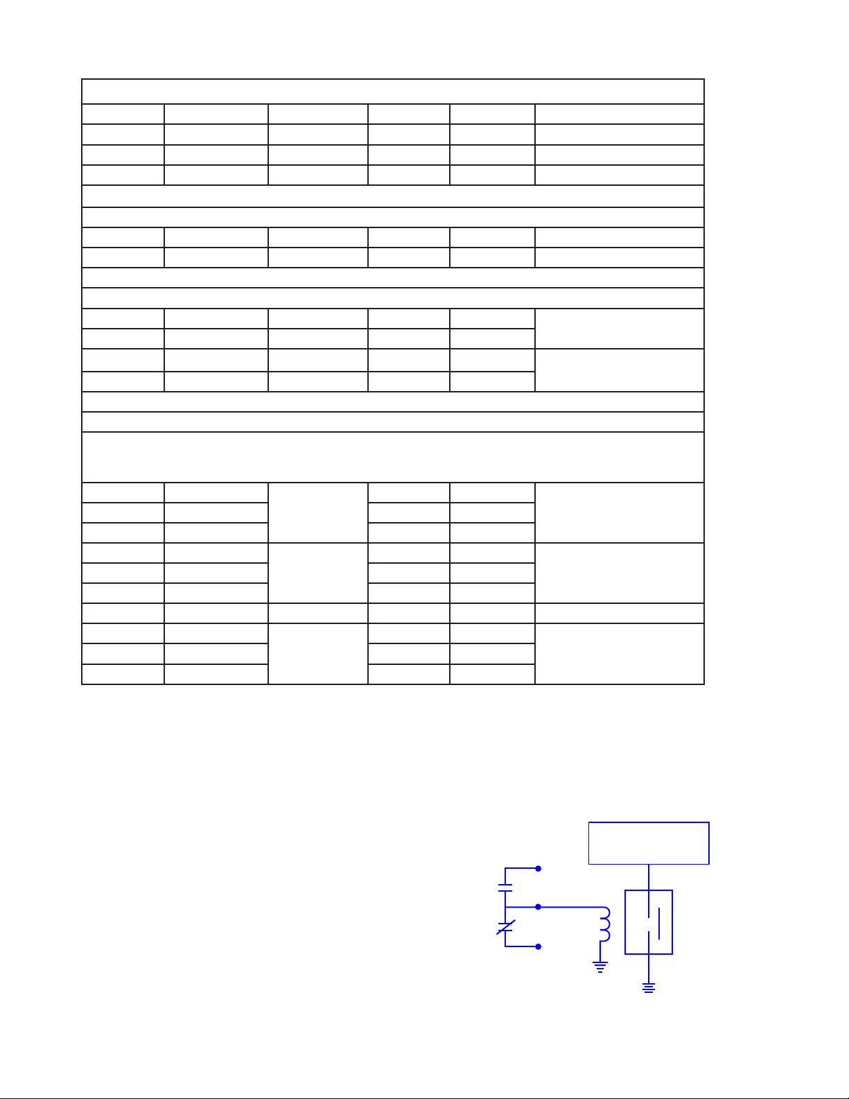
Table B — Pinouts for 40 Pin Connector Interface to CXCR
1 DIN1 2 DIN2 Output circuit breaker CB5
3 D_COM Fused DC- 4 DIN3 MBS
5 DIN4 6 DIN5 Input circuit breaker CB6
7 D_COM Fused DC- 8 DIN6 TVSS
Not Used
9 N/A 10 N/A
11 N/A 12 N/A
Analog Inputs
13 V1+ 14 T1+
15 V1- 16 T1-
17 I1+ 18 T2+
19 I1- 20 T2-
Relay Contacts (rated at 60VDC or 42V AC, 0.5A)
From the factory, the Cordex controller is congured with the relay assignments shown below. The relays can
be unassigned from their factory conguration and remapped. For example Relay 2, K2, can be unassigned
from LVD #2 then remapped as an alarm relay. Refer to the Cordex controller manual for details.
21 K1_NO
LVD #1
25 K1_COM 26 K2_COM
27 K3_NO
LVD #3
31 K3_COM 32 K4_COM
33 Not installed 34 Not installed
35 K5_NO
Power System
Major alarm
39 K5_COM 40 K6_COM
22 K2_NO
28 K4_NO
36 K6_NO
Battery temperature probe
(Figure 6)
Battery temperature probe
(Figure 6)
LVD #223 K1_NC 24 K2_NC
Power System Minor alarm29 K3_NC 30 K4_NC
AC Mains High/Low alarm37 K5_NC 38 K6_NC
2.4 Low Voltage Battery Disconnect (Optional)
A built-in AMPS24 shutdown cuts off the load
during a lengthy power outage.
Installing an LVD (Alpha part number 020615-20), between the AMPS24 HP and the
batteries, disconnects the AMPS24 HP from
the batteries to prevent further drain of the
batteries during a lengthy power outage.
The controller is configured with a relay
assigned to LVD #1. Figure 5 shows how to
wire the normally closed contacts of the LVD
#1 relay to activate the LVD. The activation
value is set in the Controls >LVD Control
menu—see the controller software manual.
16
Pinouts available at the AMPS24 40 pin connector
– see Figure 4 and (Table B.
LVD#1
K1 Relay
-48V@Pin 3
AMPS24 HP
Pin 21
Pin 25
LVD
Pin 23
Batteries
Figure 5 — LVD wiring
Doc. #: 0260011-J0 Rev B
Page 19
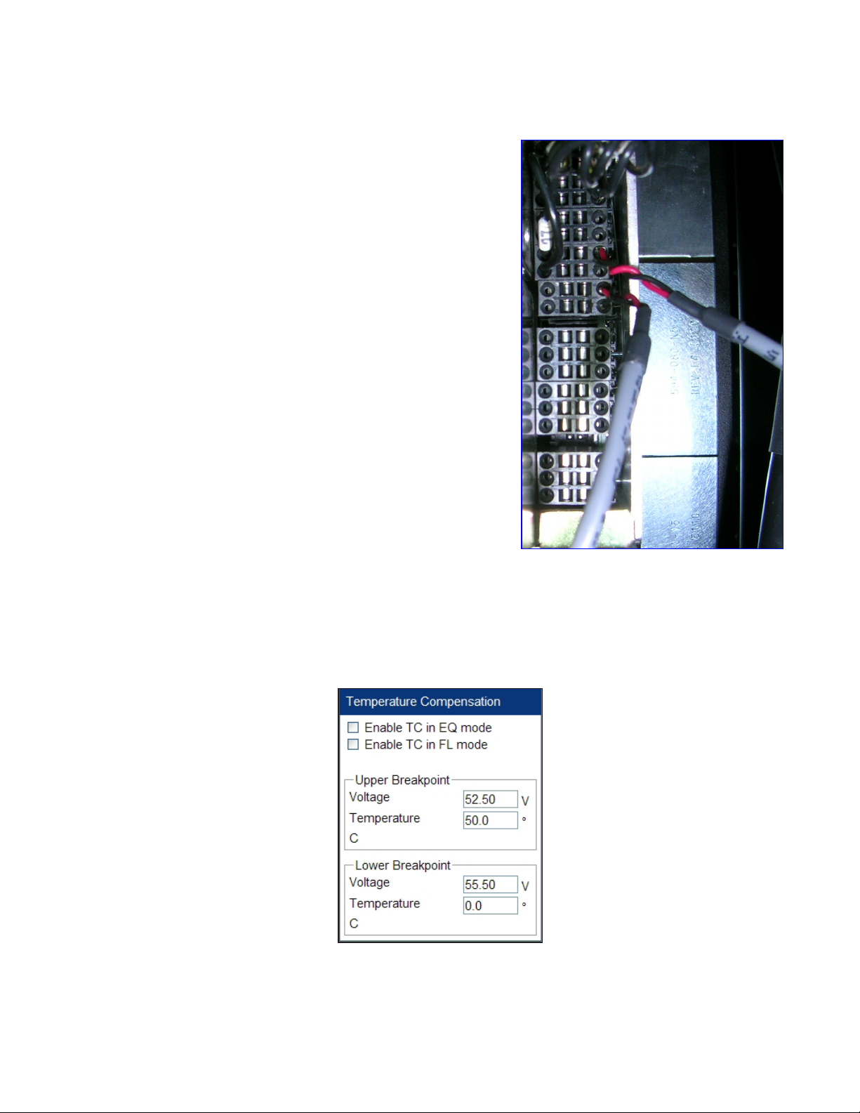
2.5 Battery Temperature Probes
Adjusting the battery’s float or equalize voltage to
correspond with temperature fluctuations ensures
maximum battery performance and life expectancy.
The CXC’s built-in automatic temperature
compensation function adjusts the system every ten
minutes as the temperature changes and changes the
voltage by a maximum of 0.1 V during this interval.
A battery probe from a single string can be connected
to pins #18 and #20 of the AMPS24 HP 40-pin
connector. Figure 6 shows the connection of two
battery probes where pins #14 and #16 are used for
the second probe.
Connection Procedure
1. Use needle nose pliers to remove the terminal
block.
2. Connect the battery temperature probes,
3. To calibrate the temperature probes, refer to
Analog Signal Calibration in the CXCU manual or
to the alpha website (www.alpha.ca): Technical
Documentation > Method of Procedures
> Cordex > Controller > Calibration –
Temperature (web interface).
4. Complete the Batteries > Battery Properties
parameters to enable the Temperature
Compensation feature. The Battery Properties window contains information provided by the
battery manufacturer.
Figure 6 — Battery temperature probes
5. Set up temperature compensation in Batteries > Configure Batteries—see Figure 7.
Doc. #: 0260011-J0 Rev B
Figure 7 — Batteries > Configure Batteries
17
Page 20
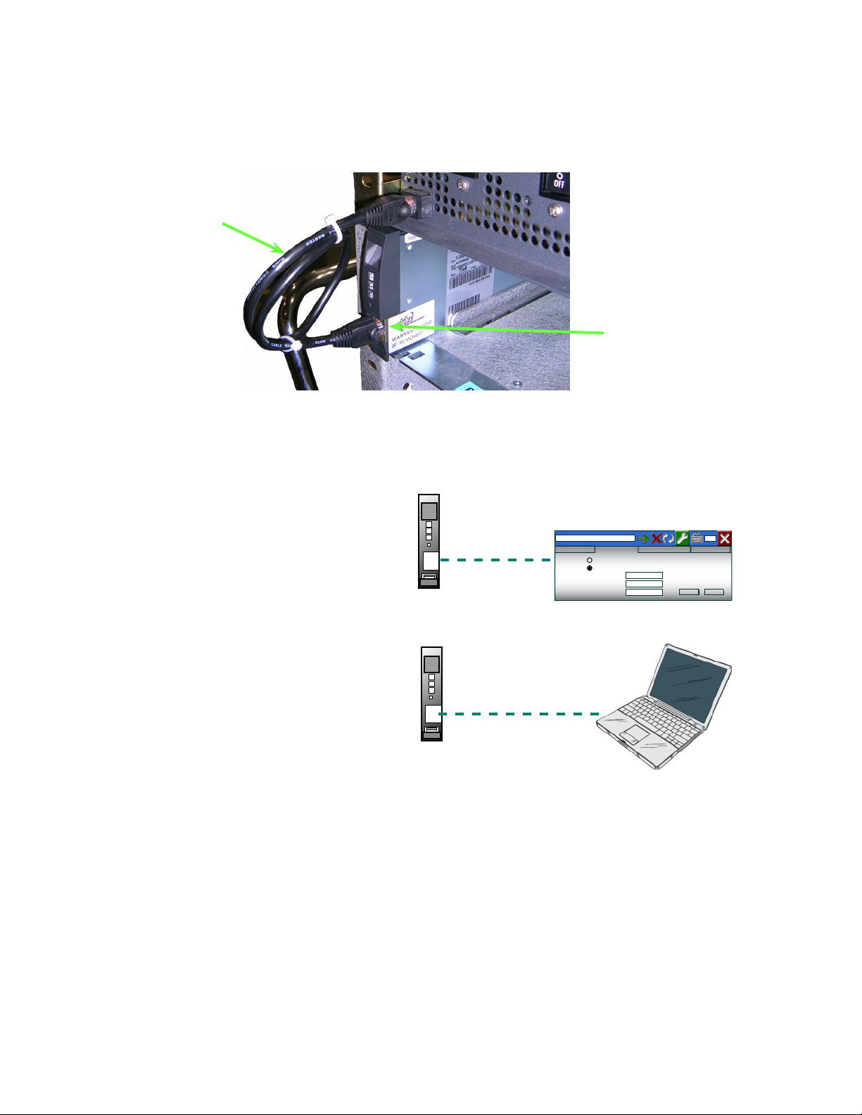
2.6 Network Requirements
The CXCU has a single Ethernet port on its front panel for communication with either the graphic
display or a laptop.
Cable that connects
the CXCU to the
graphic display
Figure 8 — Cable connection to CXCU for graphic display
CXCU RJ45
connection
2.6.1 Single Connection
The graphic display, which
uses a browser to launch CXC
web pages, is installed in
the DC distribution shelf (see
Figure 1). This display connects
to the Ethernet port on the front
of the CXCU.
To use a laptop to configure the
system, disconnect the graphic
display cable from the RJ45
jack on the CXCU (Figure 8).
Connect the laptop to the RJ45
jack with an Ethernet crossover
cable.
CXCU installed
in AMPS24 HP shelf
Ethernet
connector
Ethernet
connector
Figure 9 — Single network connection to CXCU
OR
Graphic Display
http://10.10.10.201/
Obtain an IP Address Using DHCP
Use the following IP Address
IP Address:
10. 10. 10. 202
Subnet Mask:
255. 255. 255. 0
Default Gateway:
PC running IE8.0
or Firefox
Application SettingsCXC Connection SettingsIP Protocol SettingsConnection Status
Cancel Apply
18
Doc. #: 0260011-J0 Rev B
Page 21
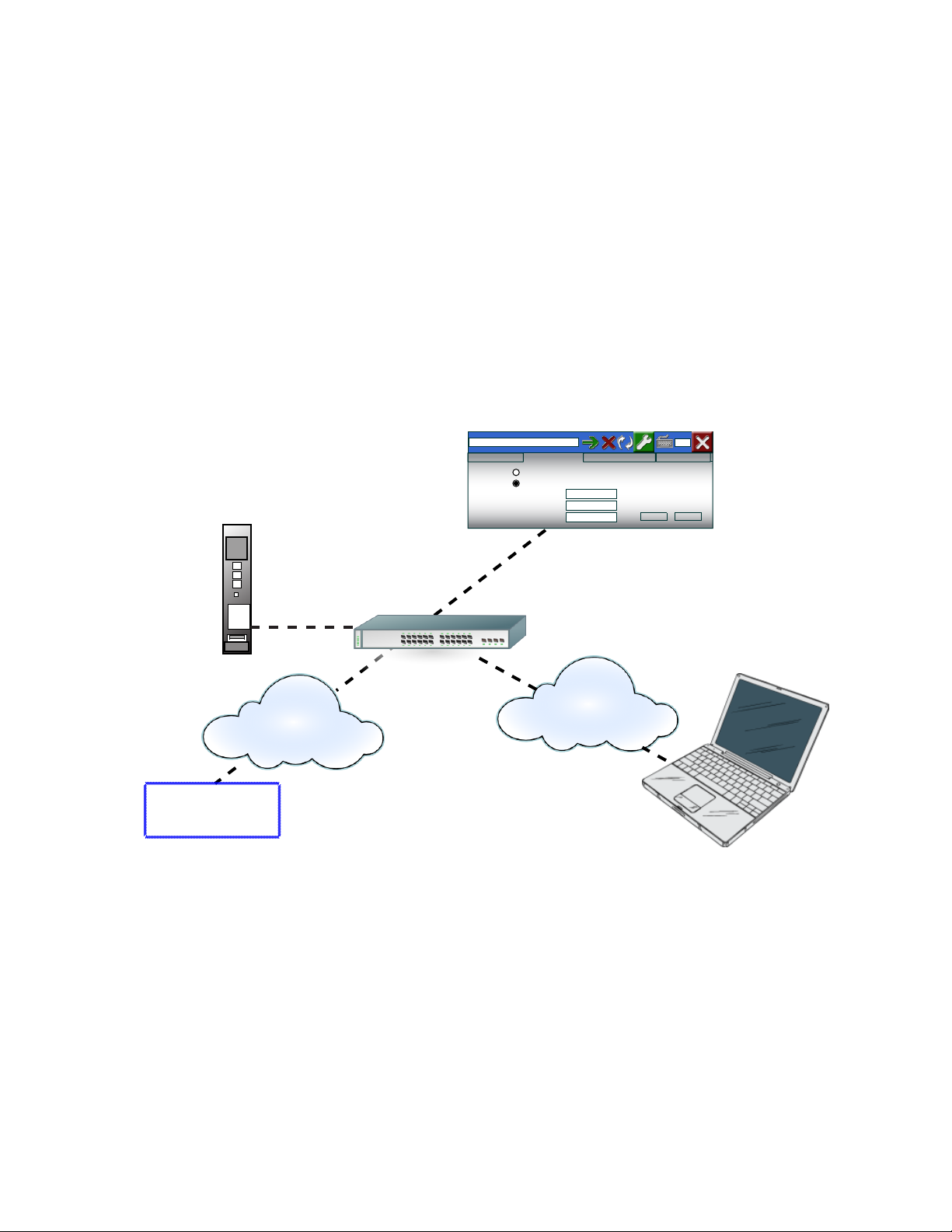
2.6.2 Multiple Connections
Since the CXCU controller only has one port, a switch must be used for the following requirements:
• Simultaneous display at the graphic display and a local laptop
• Local display at the graphic display and remote Simple Network Management Protocol (SNMP) /
Ethernet functionality
Alpha Technologies has tested the Netgear JFS516 network switch, but network switches with the following
functionality will work:
• Network Interface: RJ-45 connector for 10BASE-T or 100BASE-TX Ethernet interface
• Meets IEEE 802.3i 10BASE-T Ethernet, IEEE 802.3u,100BASE-TX Fast Ethernet
• Meets IEEE 802.3x Flow Control; compatible with Windows®
Graphic Display
http://10.10.10.201/
Obtain an IP Address Using DHCP
Use the following IP Address
IP Address:
10. 10. 10. 202
Subnet Mask:
255. 255. 255. 0
Default Gateway:
Application SettingsCXC Connection SettingsIP Protocol SettingsConnection Status
Cancel Apply
CXCU
Ethernet
connector
Remote Network
Access
PC running
IE7.0 or greater
or Firefox
Router or switch
Ethernet
Ethernet
PC running IE8.0
or Firefox
Figure 10 — Multiple network connections to the CXCU
Doc. #: 0260011-J0 Rev B
19
Page 22
3. Power Configurations
This section lists the power configurations available with the AMPS24 system and defines the
terminology used throughout this manual.
3.1 Power System Configuration Terminology
3.1.1 120Vac Single Phase
A single phase system is 120Vac from L1 to N (neutral).
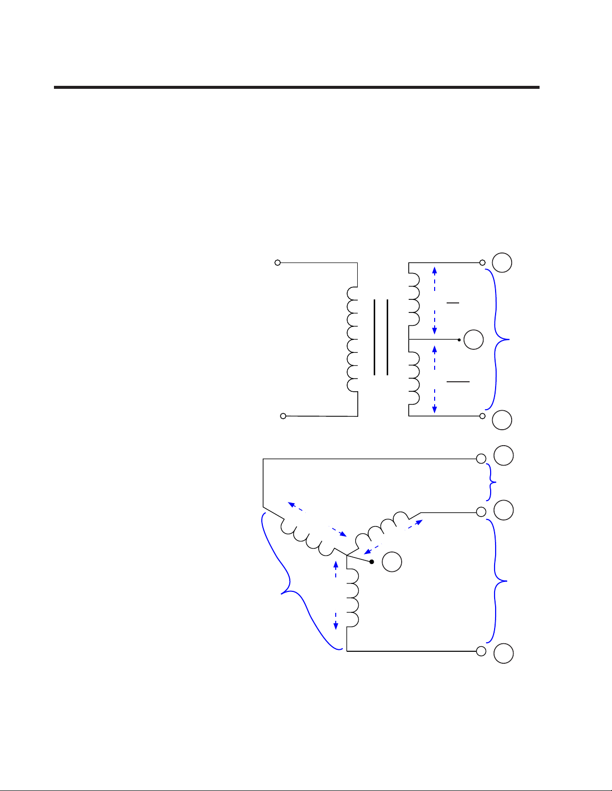
3.1.3 120/240Vac Split Phase
The term 120/240Vac SPLIT PHASE
is used throughout this manual to
identify the “3-wire/ 2 legs from a
single phase supply” configuration
shown in Figure 11.
3.1.2 120/208Vac 2-Pole
The term 120/208 2-POLE is used
throughout this manual to identify
the “2-pole from a 3-phase supply”
configuration such as L2 to L3 shown
in Figure 12.
120V /0°
N
120V /180°
Figure 11 — Split Phase from a Single phase supply
120V
120V
L1
240V
L2
L1
208V
L2
3.1.4 120/208Vac 3-Phase
Each phase conductor is 120 degrees out of phase with the other, as shown in Figure 12. All three
phases (3-pole) plus the neutral are used.
20
N
208V
Figure 12 — 2-Pole from a 3-phase supply
120V
208V
L3
Doc. #: 0260011-J0 Rev B
Page 23
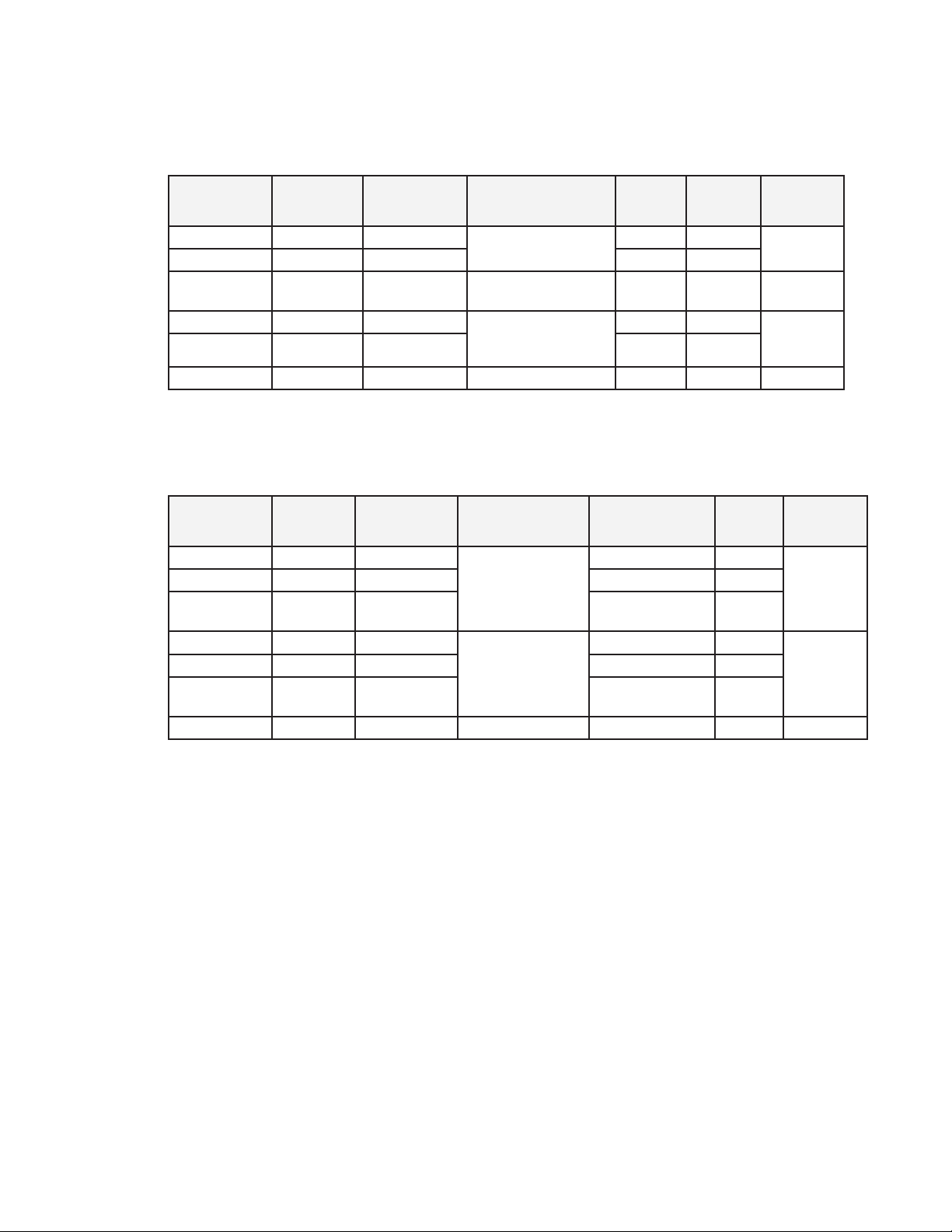
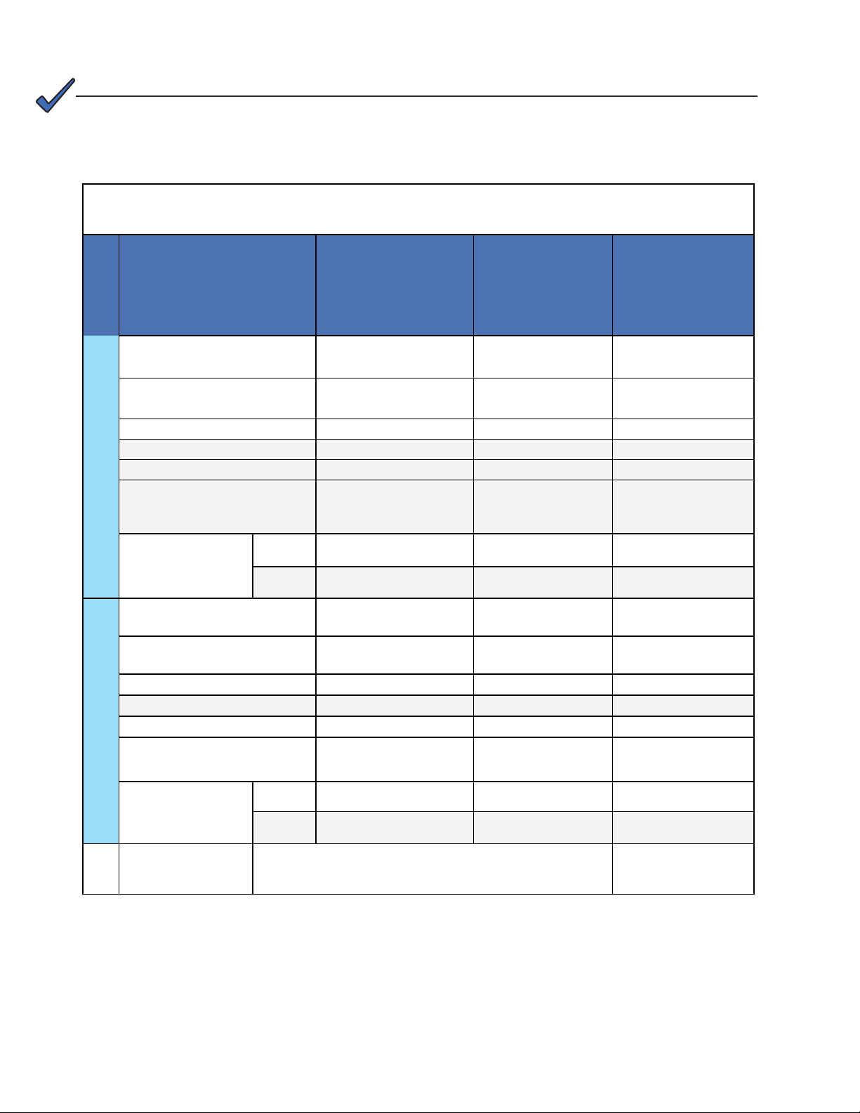
3.2 4i Shelf Systems (No Battery Charger)
The 4i systems, with up to 4 AIM1500 modules per shelf, do not have an integrated 48V charger. The
following table shows available configurations: refer to the section in the last column for more details.
System Part
Number
0260012-201 6kVA 4.8 kW
0260012-203 12kVA 9.6 kW 2 8
0260012-202
(no LCD)
0260012-204 12kVA 9.6 kW 120/208 V 2-phase
0260012-206 24kVA 19.2 kW 4 16
0260012-205 18kVA 14.4 kW 120/208 V 3-phase 3 12 Section 3.7
Max AC
output VA
" " " " " "
Max AC
output power
AC Input and
Output voltage
120 V single phase
or
120/240 V split phase
# of 4
Inverter
shelves
1 4
2 8
Max # of
AIM1500
modules
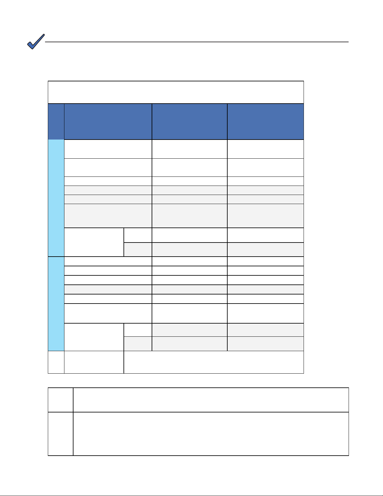
3.3 3i+1R Shelf Systems (Integrated Battery Charger)
3i+1R Shelf Systems have 1 rectifier per shelf and up to 3 inverters per shelf.
System Part
Number
0260011-101 4.5kVA 3.6 kW
0260011-102 9kVA 7.2 kW 2 x 3i+1R shelves 6
0260011-104
0260011-103
0260011-106 18kVA 14.4 kW 4 x 3i+1R shelves 12
0260011-107
0260011-105 13.5kVA 10.8 kW 120/208 V 3-phase 3 x 3i+1R shelves 9 Section 3.7
Max AC
output VA
10.5kVA 8.4 kW 1 x 3i+1R shelf
9kVA 7.2 kW
21kVA 16.8 kW 2 x 3i+1R shelf
Max AC
output power
AC Input and
Output voltage
120 V single phase
120/208 V 2-pole
or
120/240 V split
phase
# of 3i+1R
shelves
1 x 3i+1R shelf 3
plus 1 x 4i shelf
2 x 3i+1R shelves 6
plus 2 x 4i shelf
Max # of
AIM1500
modules
14
Reference
Section 3.5
Section 3.6
Reference
Section 3.5
7
Section 3.6
3.4 System Spares
See "Table J — Spare Parts" on page 69.
Doc. #: 0260011-J0 Rev B
21
Page 24
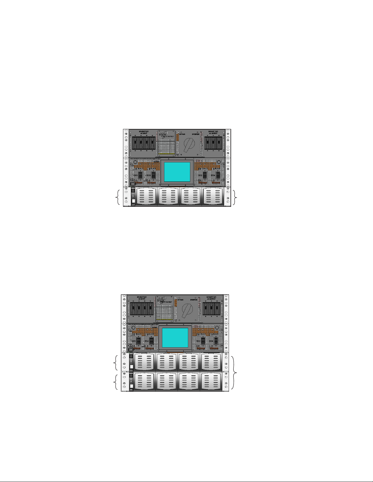
3.5 120V Single Phase Systems
See the facility planning data sheets for the two configurations shown below:
• "Table C — 10.5kVA, 9kVA and 4.5kVA, 120V Single Phase 3i+1R Shelf Systems" on page 23
• "Table D — 12kVA and 6kVA, 120V Single Phase, 4i Shelf Systems" on page 24
Configurations for a Single Shelf
• 4i shelf
• 3i+1R shelf
DC 1
Configurations for Two Shelves
• two 4i shelves
• two 3i+1R shelves
• one 3i+1R shelf and one 4i shelf
DC 1
DC 2
Phase 1
Phase 1
22
Doc. #: 0260011-J0 Rev B
Page 25
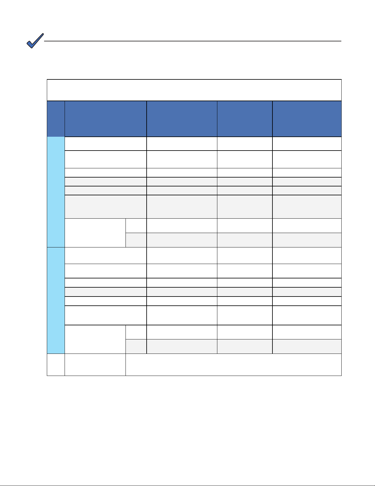
NOTE:
The recommendations in Table C are for reference only. A registered professional engineer
must review and approve or modify these recommendations in compliance with applicable
national and local electrical and building codes.
Table C — 10.5kVA, 9kVA and 4.5kVA, 120V Single Phase 3i+1R Shelf
Systems
Models
AC Input Voltage 120V 120V 120V
Full Load AC Input Current
(per phase)
AC Input poles & wiring 2w +G 2w + G 2w + G
Wiring 1 pole 1 pole 1 pole
SCCR 2100A 2100A 1600A
Recommended
AC Input
AC input Breaker/fuse
(Note: 2)
Recommended
AC Input Wire size,
90ºC copper (Note 1)
Total AC Output (Max)
AC Output Voltage 120V 120V 120V
AC Output poles & wiring 2w +G 2w +G 2w +G
Wiring 1 pole 1 pole 1 pole
AC Output Current (per Phase) 87.5A 75A 37.5A
NEC
50ºC
CEC
50ºC
AMPS24-1-10.5-H1-i1
#0260011-104
108A 108A 54A
125A 120A 70A
1 1/0 6
1/0 1/0 4
10.5kVA/
8.4kW
AMPS24-1-9-H2
#0260011-102
9kVA/7.2kW 4.5kVA/3.6kW
AMPS24-1-4.5-H1
#0260011-101
Installed Inverter Output
Circuit Breaker 100% rated
AC Output
Recommended
AC Input Wire size,
90ºC copper (Note 1)
AC Input & Output
connection terminals
Doc. #: 0260011-J0 Rev B
100A 100A 70A
NEC
50ºC
CEC
50ºC
Box lugs are rated for both Aluminum and Copper wire, #2/0 to #6 AWG. Fasten
clamping screw to 120 in-lbs (14 N-m)
1 1 6
1/0 1/0 4
23
Page 26

NOTE:
The recommendations in Table D are for reference only. A registered professional engineer
must review and approve or modify these recommendations in compliance with applicable
national and local electrical and building codes.
Table D — 12kVA and 6kVA, 120V Single Phase, 4i Shelf
Systems
Models
AMPS24-2-12-i2
#0260012-203/202
AC Input Voltage 120V 120V
Full Load AC Input Current
(per phase)
AC Input poles & wiring 2w +G 2w +G
Wiring 1 pole 1 pole
SCCR 2100A 1600A
Recommended
AC Input
AC input Breaker/fuse
(Note: 2)
Recommended
AC Input Wire size,
90ºC copper (Note 1)
Total AC Output (Max)
AC Output Voltage 120V 120V
AC Output poles & wiring 2w +G 2w +G
Wiring 1 pole 1 pole
AC Output Current (per Phase) 100A 50A
NEC 50ºC
CEC 50ºC
106A 53A
150A 70A
1 6
1/0 4
12kVA/
9.6kW
AMPS24-1-6-i1
#0260012-201
6kVA/
4.8kW
24
Installed Inverter Output
Circuit Breaker 100% rated
AC Output
Recommended
AC Input Wire size,
90ºC copper (Note 1)
AC Input & Output
connection terminals
Note 1:
Note 2:
Inverter AC Input & AC Output connections: Calculations based on full load and charging current, 0.8
derating with 5 current carrying conductors, (L1,L2,L3,2xN) due to possible high harmonic content load.
Temperature correction factor for 50C applied.
Maximum AC Utility Service protection feeding the AMPS24 is 150A. Actual supply circuit breaker must
be sized appropriately for the supply wire used. Consult your local and national electrical codes. Double
neutral is strongly recommended for AC output wiring (and AC input wiring to the MBS) for 3Ф systems with
signicant non-linear (ie rectied capacitive) loads. Since the AC input to systems without MBS is power
factor corrected, AC wiring to systems without MBS does not require double neutral wiring.
100A 70A
NEC 50ºC
CEC 50ºC
Box lugs are rated for both Aluminum and Copper wire, #2/0 to #6
AWG. Fasten clamping screw to 120 in-lbs (14 N-m)
1 6
1/0 4
Doc. #: 0260011-J0 Rev B
Page 27
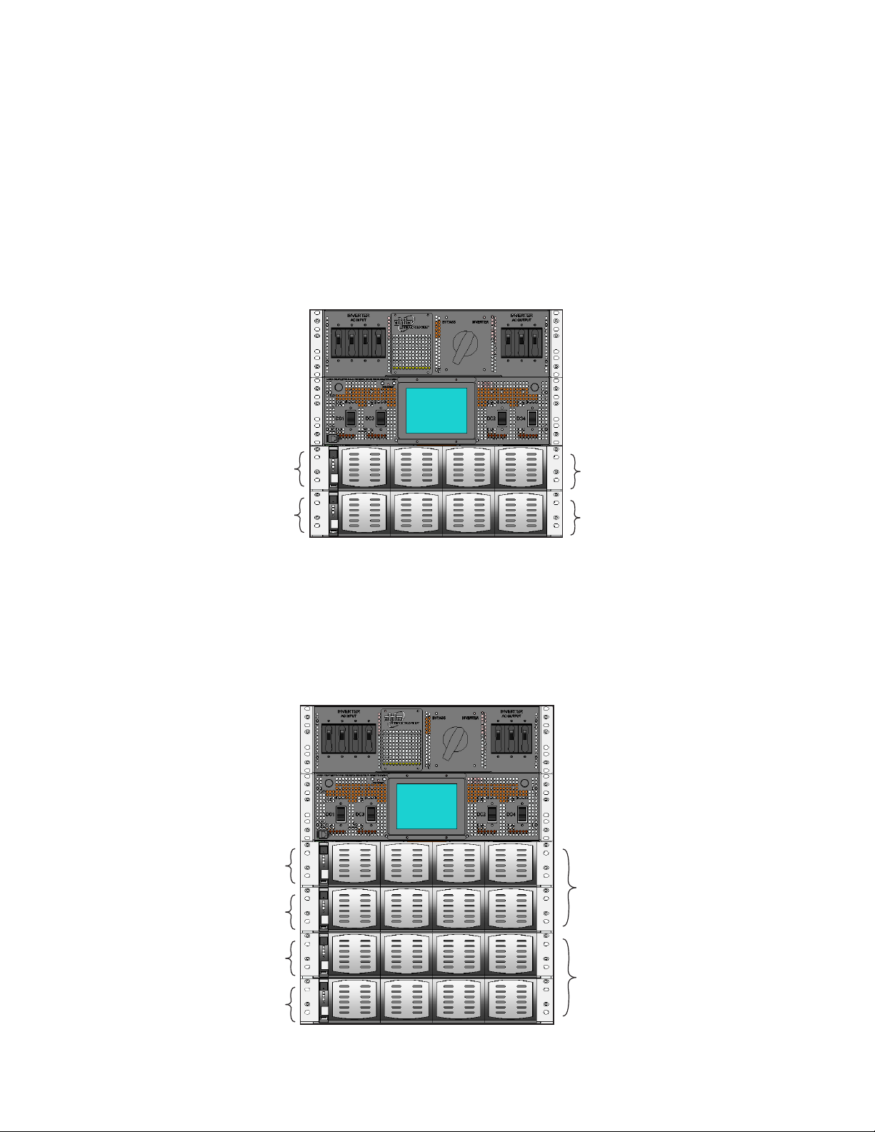
3.6 120V/240V Split Phase or 120/208V 2-Pole Systems
For facility planning data sheets, see
• "Table E — 21kVA, 18kVA, & 9.0kVA 120/240V Split Phase or 120/208 2-Pole 3i+1R Shelf Systems" on page
26 and
• "Table F — 24kVA & 12KVA 120/240V Split Phase or 120/208 2-Pole 4i shelf Systems" on page 27
Configurations for Two Shelves
• two 4i shelves (AMPS24-2-12-i2)
• two 3i+1R shelves (AMPS24-2-9-H2)
DC 1
DC 2
Configurations for Four Shelves
• four 4i shelves (AMPS24-2-24-i4)
• four 3i+1R shelves (AMPS24-2-18-H4)
• two 3i+1R shelves and two 4i shelves (AMPS24-2-21-H2-i2)
DC 1
Phase 1
Phase 2
Phase 1
DC2
DC 3
DC 4
Doc. #: 0260011-J0 Rev B
Phase 2
25
Page 28
NOTE:
The recommendations in Table E are for reference only. A registered professional engineer
must review and approve or modify these recommendations in compliance with applicable
national and local electrical and building codes.
Table E — 21kVA, 18kVA, & 9.0kVA 120/240V Split Phase or 120/208
2-Pole 3i+1R Shelf Systems
Models
AC Input Voltage 120/208V or 120/240V 120/208V or 120/240V 120/208V or 120/240V
Full Load AC Input Current
(per phase)
AC Input poles & wiring 3w + G 3w + G 3w + G
Wiring 2 pole 2 pole 1 pole
SCCR 2100A 2100A 1600A
Recommended
AC Input
AC input Breaker/fuse
(Note: 2)
Recommended
AC Input Wire size,
90ºC copper (Note 1)
Total AC Output (Max)
AC Output Voltage 120/208V or 120/240V 120/208V or 120/240V 120/208V or 120/240V
NEC 50ºC
CEC 50ºC
AMPS24-2-21-H2-i2
0260011-107
118A 121A 61A
150A 150A 80A
2/0 2/0 3
2/0 2/0 3
21kVA/
16.8kW
AMPS24-2-18-H4
0260011-106
18kVA/
14.4kW
AMPS24-2-9-H2
0260011-103
9kVA/
7.2kW
26
AC Output poles & wiring 3w + G 3w + G 3w + G
Wiring 2 pole 2 pole 1 pole
AC Output Current (per Phase) 87.5A 75A 37.5A
Installed Inverter Output
Circuit Breaker 100% rated
AC Output
Recommended
AC Input Wire size,
90ºC copper (Note 1)
AC Input & Output
connection terminals
NEC 50ºC
CEC 50ºC
Box lugs are rated for both Aluminum or Copper wire, #2/0 to
#6 AWG. Fasten clamping screw to 120 in-lbs (14 N-m)
100A 100A 70A
2/0 2/0 3
2/0 2/0 3
Doc. #: 0260011-J0 Rev B
Page 29
NOTE:
The recommendations in Table F are for reference only. A registered professional engineer
must review and approve or modify these recommendations in compliance with applicable
national and local electrical and building codes.
Table F — 24kVA & 12KVA 120/240V Split Phase or 120/208
2-Pole 4i shelf Systems
Models
AC Input Voltage 120/208V or 120/240V 120/208V or 120/240V
Full Load AC Input Current
(per phase)
AC Input poles & wiring 3w + G 3w + G
Wiring 2 pole 2 pole
SCCR 2100A 1600A
Recommended
AC Input
AC input Breaker/fuse
(Note: 2)
Recommended
AC Input Wire size,
90ºC copper (Note 1)
Total AC Output (Max) 24kVA/19.2kW 12kVA/9.6kW
AC Output Voltage 120/208V or 120/240V 120/208V or 120/240V
AC Output poles & wiring 3w + G 3w + G
Wiring 2 pole 2 pole
AC Output Current (per Phase) 100A 50A
NEC 50ºC
CEC 50ºC
AMPS24-2-24-i4
0260012-206
106A 53A
150A 70A
2/0 4
2/0 4
AMPS24-2-12-i2
0260012-204
Installed Inverter Output
Circuit Breaker 100% rated
AC Output
Recommended
AC Input Wire size,
90ºC copper (Note 1)
AC Input & Output
connection terminals
Note 1:
Note 2:
Doc. #: 0260011-J0 Rev B
Inverter AC Input & AC Output connections: Calculations based on full load and charging current, 0.8
derating with 5 current carrying conductors, (L1,L2,L3,2XN) due to possible high harmonic content load.
Temperature correction factor for 50C applied.
Maximum AC Utility Service protection feeding the AMPS24 is 150A. Actual supply circuit breaker must
be sized appropriately for the supply wire used. Consult your local and national electrical codes. Double
neutral is strongly recommended for AC output wiring (and AC input wiring to the MBS) for 3Ф systems with
signicant non-linear (ie rectied capacitive) loads. Since the AC input to systems without MBS is power
factor corrected, AC wiring to systems without MBS does not require double neutral wiring.
100A 70A
NEC 50ºC
CEC 50ºC
Box lugs are rated for both Aluminum and Copper wire, #2/0 to #6
AWG. Fasten clamping screw to 120 in-lbs (14 N-m)
2/0 4
2/0 4
27
Page 30
3.7 120V/208V 3-Phase Systems
For facility planning data sheet, see "Table G — 18kVA and 13.5kVA, 120V/208V 3-Phase Systems"
on page 29.
Configurations for 3-Phase Three Shelf
• three 4i shelves (AMPS24-3-18-i3)
• three 3i+1R shelves (AMPS24-3-13.5-H3)
DC 1
DC 2
DC 3
Phase 1
Phase 2
Phase 3
28
Doc. #: 0260011-J0 Rev B
Page 31

NOTE:
The recommendations in Table G are for reference only. A registered professional engineer
must review and approve or modify these recommendations in compliance with applicable
national and local electrical and building codes.
Table G — 18kVA and 13.5kVA, 120V/208V 3-Phase
Systems
Models
AMPS24-3-18-i3
(4i Shelf)
0260012-205
AC Input Voltage 120/208V 120/208V
Full Load AC Input Current
(per phase)
AC Input poles & wiring 4 w + G 4 w + G
Wiring 3Ф Wye 3Ф Wye
SCCR 1600A 1600A
Recommended
AC Input
AC input Breaker/fuse
(Note: 2)
Recommended
AC Input Wire size,
90ºC copper (Note 1)
Total AC Output (Max) 18 kVA/ 14.4kW 13.5 kVA/ 10.8kW
AC Output Voltage 120/208V 120/208V
AC Output poles & wiring 4 w + G 4 w + G
Wiring
AC Output Current (per Phase) 50A 37.5A
NEC 50ºC
CEC 50ºC
56A 59A
80A 80A
4 4
3 3
3Ф Wye 3Ф Wye
AMPS24-3-13.5-H3
(3i+1R Shelf)
0260011-105
Installed Inverter Output
Circuit Breaker 100% rated
AC Output
Recommended
AC Input Wire size,
90ºC copper (Note 1)
AC Input & Output
connection terminals
Note 1:
Note 2:
Doc. #: 0260011-J0 Rev B
Inverter AC Input & AC Output connections: Calculations based on full load and charging current, 0.8
derating with 5 current carrying conductors, (L1,L2,L3,2XN) due to possible high harmonic content
load. Temperature correction factor for 50C applied.
Maximum AC Utility Service protection feeding the AMPS24 is 150A. Actual supply circuit breaker
must be sized appropriately for the supply wire used. Consult your local and national electrical
codes. Double neutral is strongly recommended for AC output wiring (and AC input wiring to the
MBS) for 3Ф systems with signicant non-linear (ie rectied capacitive) loads. Since the AC input to
systems without MBS is power factor corrected, AC wiring to systems without MBS does not require
double neutral wiring.
70A 70A
NEC 50ºC
CEC 50ºC
Box lugs are rated for both aluminum or copper wire, #2/0 to #6
AWG. Fasten clamping screw to 120 in-lbs (14 N-m)
4 4
3 3
29
Page 32

3.8 AMPS24 HP - Recommended DC Breaker and Wire Sizes
NOTE:
The recommendations in this table are for reference only. A registered professional engineer must review and approve or modify these recommendations in compliance with applicable national and local electrical and building codes.
Maximum wire gauge size is 350 kcmil; 4/ 0 or smaller is recommended, 90°C or better copper only.
Model Recommended minimum DC Breaker
rating (100% rated per feed),
Single DC feed Dual DC feed
AMPS24-2-24 x 300 21.4 kW 480 A
AMPS24-2-21 x 250 18.7 kW 406 A
AMPS24-2-18 x 225 16 kW 333 A
AMPS24-2-9 250 125 8 kW 166 A
AMPS24-2-12 300 150 10.7 kW 240 A
AMPS24-3-18 x 225 16 kW 350 A
AMPS24-3-13.5 350 175 15 kW 250 A
AMPS24-1-10.5 250 125 9.4 kW 203 A
AMPS24-1-12 300 150 10.7 kW 240 A
AMPS24-1-9 250 125 8 kW 166 A
AMPS24-1-6 150 75 5.4 kW 120 A
AMPS24-1-4.5 120 60 4 kW 83 A
Maximum DC Input
Wattage
Maximum DC
Input Current @
48Vdc, full load
Torque specifications for DC wiring (3/8" bolts that attach the DC lugs at the back of the DC
distribution box) are as follows:
• Imperial: 190 – 240 inch/lbs
• Metric: 21.5 – 27.1 N-m
30
Doc. #: 0260011-J0 Rev B
Page 33

3.9 How to Configure Inverters in AC Input Groups, AC Output
Groups and DC Input Groups
The following sections show how to distribute the inverters among the phases and also suggests how
to distribute the DC input to the inverters.
NOTE:
The groups in the software settings generally correspond to the AC phases or DC inputs.
3.9.1 AC Input Groups/ AC Output Groups
The CXCU System Controller
provides an interface to
assign inverters to phases
(Inverters > Group Mapp ing).
The logical approach is to
match the configuration of
inverters in the AC Input
Group to the configuration
of inverters in the AC Output
Group as shown.
green
black
red
orange
These groups of inverters can then be monitored as a unit in the View Group Status screen.
Figure 13 — Monitoring AC Input Groups, AC Output Groups and DC Input Groups
Doc. #: 0260011-J0 Rev B
31
Page 34

3.9.2 DC Input Groups
DC feed from the batteries to the inverters is protected by input breakers. The numbering of each DC
input breaker corresponds to the shelf it protects: DC3 input breaker, for example, protects shelf 3.
shows a four shelf, split phase system with the breakers and corresponding shelves labeled.
DC3 breaker
DC1 breaker
DC2 breaker
DC4 breaker
DC 1
Phase 1
DC2
DC 3
Phase 2
DC 4
Figure 14 — DC input breakers
Configuration of the DC input
The configuration of the DC input to the inverters provides several different ways to monitor DC input
power and input current. Table H provides possible configurations.
Table H — DC Input Groups
Monitoring DC Source
32
Bulk Assign all inverters to DC Input Group 1.
Shelf Assign Shelf 1 inverters to DC Input Group 1
Assign Shelf 2 inverters to DC Input Group 2
Assign Shelf 3 inverters to DC Input Group 3
Assign Shelf 4 inverters to DC Input Group 4
Dual Input If the system has two battery strings and makes use of the dual input feature (see 5.3.3):
• Battery 1 string is fed to the inverters through breakers DC1 (shelf 1) & DC3 (shelf 3)
• Battery 2 string is fed to the inverters through breakers DC2 (shelf 2) & DC4. (shelf 4)
To monitor Battery String 1, assign all the inverters in shelves 1 & 3 to DC Input Group 1.
To monitor Battery String 2, assign all the inverters in shelves 2 & 4 to DC Input Group 2.
The number of DC Input
Groups (maximum eight) is
set in the Inverters > Group
Mapping screen and monitored
as a unit in the View Group
Status screen.
Doc. #: 0260011-J0 Rev B
Page 35

4. System Pre-Installation
4.1 Site Selection
The power system must be mounted in a clean and dry environment.
Consider both the floor loading and the physical space required for the AMPS24 HP power system
and the batteries.
4.1.1 Floor Plan Layout
Sufficient free space must be provided at the front and rear of the power system to meet the cooling
requirements of the power system and to allow easy access to the power system components.
Consider the following before selecting a location for the AMPS24 HP power system
• Structure of building able to support the additional weight
• Enough space to meet requirements for access
• Enough space to meet cooling requirements
• Adequate space to do the install
• Route that equipment will take through the building to reach the site
• Check and record distances to load
• Check and record distances to AC power source
• Check and record distances to batteries/DC power source
• Understand the full load on the DC system
• Window for working hours and other similar restrictions
• How much and what kind of prep work can be done in advance
x Reinforce floors
x Install distribution panels
x Install cable racks
x Run wiring
x Minimize cable lengths (cost)
x Minimize cable flow and congestion
4.2 Recommended Installation Layout
• Minimum clearance front and back for installation and maintenance is 3ft (1m
• Minimum clearance front and back for for air flow is 1 foot
• Sides, top, bottom: no clearance required
Mount the AMPS24 HP system in 19" or 23" rack that is securely bolted to the floor.
Doc. #: 0260011-J0 Rev B
33
Page 36

4.3 Transporting the Cabinet
The cabinet is shipped upright on a 99 cm x 99 cm (39" x 39") pallet.
The height of the rack, including pallet and shipping material is 31" (78.7 cm).
The maximum weight of the AMPS24 rack is 123 kg/ 270 lb (4-shelf fully loaded AMPS24 modules
included).
34
Figure 15 — Shipping dimensions (in inches)
Doc. #: 0260011-J0 Rev B
Page 37

4.4 Unpacking Instructions
1. Remove 4 front screws.
2. Remove the screws that are holding the
AMPS24 against the inner frame of the
packaging (the # of screws varies depending
on the size of the AMPS24 unit, i.e. 1 shelf vs.
4 shelves).
3. Remove the 6 nails that hold
the entire packaging down
on the skid (3 nails on each
side of the box).
4. Remove entire wooden box up and over the AMPS24.
Doc. #: 0260011-J0 Rev B
35
Page 38

5. Installation
The AMPS24 is designed for installation in a controlled environment, sheltered from rain, excessive
moisture, dust and other contaminants. Mount the AMPS24 HP system in 19" or 23" rack – front or
mid-mount – that is securely bolted to the floor.
The system arrives pre-wired, and the installer is responsible for connecting the following:
• Utility input to the system (120 V line to neutral)
• Chassis and battery return to the reference ground
• Battery strings
• System to the load
5.1 Input/Output Cabling
The illustrations in the following sections show the locations of the AC input and output, and DC
connection points:
• Connection points are accessed from the back of the system.
• AC wires enter the cabinet through the AC box at the back (section 5.2).
• DC wires enter the cabinet through the DC box at the back (5.3).
Reference Notes:
The AMPS24 HP system is pre-configured from the factory for a single AC feed per phase for
inverters, an internal maintenance bypass switch, and rectifiers if present.
• If the AC input neutral is connected, remove the neutral to ground bonding wire. The neutral to
ground wire is provided for systems without AC input connections in which case the inverter
output is considered a separately derived source and the AC output neutral must be connected
to earth ground.
• In a 3-phase system equipped with an internal maintenance bypass switch and a load with a
significant distortion power factor, it is strongly recommended to provide the AC input and AC
output connection with a double neutral feed. Non-power factor corrected IT power supplies with
rectified-capacitive loads can contain high levels of 3rd harmonics, created in such 3-phase systems. The current in the neutral line can easily be twice the current in the line currents.
The required gauge of the AC input, DC+/DC- input and AC output cabling is determined by the
current rating, circuit breaker rating, typical ambient temperatures and the applicable local electrical
codes. Typically the AC input and standard AC output is 6 wires (L1, L2, and L3, N, N, G) up to
2/0 THHW or RW90 type cable that connects to the AMPS24 HP system with trade size up to 2.5"
conduit.
Refer to the appropriate model in the following sections for specific AC input and output connection
terminal torque specifications.
• Section "3.5 120V Single Phase Systems" on page 22
• Section "3.6 120V/240V Split Phase or 120/208V 2-Pole Systems" on page 25
• Section "3.7 120V/208V 3-Phase Systems" on page 28
36
Doc. #: 0260011-J0 Rev B
Page 39

Carefully review the following schematic and notes 1 through 7 before beginning the AC input and
output, and DC wiring.
Notes
1. All wiring must be in accordance with applicable electrical codes.
2. A low voltage battery disconnect (LVBD) should be provided with the battery system.
3. Inverter main input must always include a neutral connection.
4. Power and control cables must be in separate conduits.
5. N-G shorting jumper is factory installed for inverter systems only. Remove if AC input neutral is
connected. (Refer to note in Figure 16.)
6. L3 is only used with 3-phase systems.
7. Two independent battery strings can be connected. Tie bars are provided for single or dual DC
feed. (Refer to note in Figure 16.)
Doc. #: 0260011-J0 Rev B
Figure 16 — AMPS24 Power and Battery Connections
37
Page 40

5.2 AC Wiring
The two figures below provide both a representation of the AC wiring connections (Figure 17) as well
as an actual unit wired for 3-phase AC power (Figure 18).
N out N in
L1 out
L2 out
L3 out
GND out
Figure 17 — AC Wiring connections diagram
Customer connections
GND in
L1 in
L2 in
L3 in
38
Figure 18 — AC Wiring (shown for 3-phase)
Doc. #: 0260011-J0 Rev B
Page 41

5.3 DC Battery and Ground Cabling
5.3.1 Hardware and Torque Specifications
The DC wiring is attached with 3/8” hardware (1” bolt, washer, spring washer) and 8 are provided
with each AMPS24 system (2 per each of the 4 bolting locations). However, the crimp or lug is not
provided.
The crimp/lug can either be on 1” centers with 3/8” or ½” holes, or 1.75” centers with ½” holes only.
Bus bar tie kits for DC- are included to give the installer the option to make a single battery
connection or two separate battery connections (A/B feeds).
Torque specifications for DC wiring (3/8" bolts that attach the DC lugs at the back of the DC
distribution box) are as follows:
• Imperial: 190 – 240 inch/lbs
• Metric: 21.5 – 27.1 N-m
5.3.2 DC Battery Wiring – Single Feed
The following figures show a unit wired for single feed with two battery strings in parallel.
DC minusTie Bar
NOTE: the
wire lugs
shown are
for illustration
only. They
are not supplied with the
equipment.
DC plus
GND
To MGB
+
+
–
–
GND
AC
Doc. #: 0260011-J0 Rev B
AMPS24 HP
Figure 19 — Single feed, parallel battery strings
39
Page 42

5.3.3 DC Wiring Dual Feed – with Tie Bar
The following figure shows a unit wired for dual feed with two battery strings in parallel.
NOTE: the
wire lugs
shown are
for illustration
only. They
are not supplied with the
equipment.
Tie Bar
DC minus
Feed 1
DC minus
Feed 2
DC plus
Feed 1
DC plus
Feed 2
Ground
40
+
+
To
MGB
–
–
AMPS24 HP
Figure 20 — Dual feed, two battery strings in parallel
AC
Doc. #: 0260011-J0 Rev B
Page 43

5.3.4 DC Battery Wiring with Independent Dual A/B Feed
CAUTION!
Dual feed provides capacity sharing, but NO REDUNDANCY. The loss of one battery string
will result in the loss of half the inverters.
DC minus
Feed 2
DC plus
Feed 2
DC minus
Feed 1
DC plus
Feed 1
GND GND
Doc. #: 0260011-J0 Rev B
+
+
To
MGB
–
–
AMPS24 HP
Figure 21 — DC battery wiring with independent dual A/B feed
AC
41
Page 44

5.4 DC Ground
5.4.1 Inverter Only Systems
Ground reference is at the DC source, as shown in Figure 22
– –
AC
DC Plant
+
MGB
Figure 22 — DC ground, inverter only systems
5.4.2 Inverter plus Rectifier System
Refer to Figure 19 and Figure 20.
+
AMPS24 HP
AC
42
Doc. #: 0260011-J0 Rev B
Page 45

5.5 AMPS24 HP with External Maintenance Bypass Switch
An external MBS switch allows the entire AMPS24HP system to be taken offline for maintenance.
Figure 23 shows the logical interconnections. It is not a detailed representation of the actual system
wiring.
AC
24
Figure 23 — Representative system wiring for AMPS24 HP system with MBS
5.5.1 External MBS Installation
Install and test the MBS before beginning installation of the AMPS24 HP system.
1. Install the MBS according to the instructions in the MBS installation manual.
2. Place the bypass switch in both BYPASS and UPS and test the continuity at the dedicated AC
distribution panel (see Figure 23).
5.6 Generator Automatic Transfer Switch
An on-site Automatic Transfer Switch (ATS) for a generator (see Figure 23) must meet either of the
following requirements:
• Uses an open-transition transfer switch that has a minimum open time of one second for a re-
transfer from generator to utility or from utility to generator testing, or
• If the transfer is less than one second, then ATS monitors phase angle and will only initiate a
transfer if the two sources are within +/-30 degrees of synchronization.
Doc. #: 0260011-J0 Rev B
43
Page 46

5.7 Commissioning the System for the First Time
Tools Required
The following tools are required to commission the AMPS24 HP system for the first time:
• Medium flat screwdriver with approximately 3/8" (5 mm) blade width
• True RMS digital multimeter
• Computer with Ethernet port and Internet Explorer 7 or later
• Crossover Ethernet cable if a computer is directly connected to the CXCU controller
• Straight through Ethernet cable if the network connections are made through a router or hub
• Torque wrench
• 3/8" hex driver
WARNING!
The AMPS24 HP must have no power (utility breaker OFF and locked out) and no modules
installed prior to start-up.
Before you begin:
1. Verify that the AMPS24 HP system is mechanically secured to the rack or other structure.
2. Verify that the clearances around the AMPS24 system meet the minimum requirements (see 4.1).
3. Ohm-test the AC and DC bus bars to check for any shorts caused by cut wires, loose bolts,
washers and other conductive material. If possible do Megger testing.
4. Verify that the AMPS24 HP system is correctly and securely grounded to the building grounding
system.
5. Verify that the AMPS24 HP system is correctly and securely connected to the utility and batteries:
a. For the battery connections, follow the manufacturer's recommendations and record the
torques.
b. For the AC connections, torque 2/0 to 14 AWG wire to 120 in-lbs (14 N-m).
c. Triple check the polarity of the battery connections.
6. If this is a 3i+1R shelf system that includes rectifiers for charging, verify that all rectifier modules
are removed.
7. Verify that all breakers at the external load distribution box are switched OFF.
8. Refer to "Figure 1 — AMPS24 HP System Components" and verify that the following breakers are
OFF
• AC Input circuit breaker
• Inverter AC Output circuit breaker
• DC breakers
44
9. Place the internal maintenance bypass switch (MBS) in INVERTER mode.
10. If a Generator is installed, verify that the transfer switch has a minimum 1 second switching delay
or that the transfer is always in phase (+/- 30 deg). (After the installation is complete, see 10.2.3
to set the configuration parameter for Walk-in mode.)
Doc. #: 0260011-J0 Rev B
Page 47

Starting-up the system
11. Switch on the AC mains/utility power.
12. Refer to illustration "AC Wiring" on page 38 and verify the AC input
voltages at the AC wiring terminals:
System Voltage Value
ALL Neutral to Earth Ground ~0V
3 phase L1 to L2, L2 to L3, L3 to L1 ~208V
Neutral to L1 / L2 / L3 ~120V
2-pole L1 to L2 ~208V
Neutral to L1 / L2 ~120V
Split Phase L1 to L2 ~240V
Neutral to L1 / L2 ~120V
13. Check that the battery polarity is correct.
14. Turn on the AMPS24 DC Input breakers for each installed shelf.
15. Switch on the external battery breakers or complete the fuse circuit.
16. Verify that the system starts up and that the controller switches on:
the controller display initializes with three LEDs blinking while a selftest runs for 15 seconds. (Ignore any alarm conditions indicated by
the bottom two LEDs.)
Figure 24 — Controller
The graphic display shows the correct DC voltage.
Figure 25 — Controller default home screen
Doc. #: 0260011-J0 Rev B
45
Page 48

Connecting a laptop
17. If you prefer to use a laptop to connect to the CXCU controller, refer to section 2.6.1 in this manual
and “Establishing a Network Connection via a Crossover Cable” section in the Cordex Controller
Software manual.
Installing One Seed Module per Phase
You are now going to configure the system with just one inverter per phase. Position each inverter in
the same shelf position per phase.
Phase 1
Phase 2
Figure 26 — Placement of initial inverters (shown for split phase system)
18. Install only one inverter "seed module" per phase according to the instructions in Figure 28 and
Figure 29 on page 47.
19. Switch on the inverter AC input breaker on the AMPS24 HP front panel.
20. Verify that the AC input LEDs turn on for each module. The LEDs may flash in different colors but
this behavior is not a cause for concern.
AC input LED
Install ONLY ONE INVERTER
PER PHASE. Position it in
the right most slot of the top
shelf for each phase.
46
Figure 27 — Inverter module showing AC input LED
Doc. #: 0260011-J0 Rev B
Page 49

Insertion/ Removal instructions for Inverter Modules
See below for detailed module insertion/removal instructions. You may not want to close/lock the
grill at this time because the module may have to be removed at a later stage.
CAUTION!
Improper installation or removal of modules can break latching components.
Unlock
Insert a at head screw driver into the center ap
notch and pry open the center ap. Then pull out the
module by pulling on the center ap with both hands.
Figure 28 — Unlocking and locking an inverter module for removal or insertion
Lock
Leave the module plastic front grill in the open/unlocked position, then slide/push the module all the
way into the module slot, and then close the ap.
1. Place module into shelf.
Doc. #: 0260011-J0 Rev B
2. Press module into place and
ensure connection is engaged.
Figure 29 — Inserting and removing an inverter module
3. Close cover and snap
module into place. If the
cover does not close
easily, repeat Step 2.
47
Page 50

21. Use the CXCU GUI as follows to verify that the modules are recognized and the voltages and
currents of the modules are displayed. (Ignore any alarms at this point. The current readings at
no load are not very precise.)
a. Select Inverters > View Live Status.
b. In the Inverter Report screen, locate the module for AC phase 1 by clicking each row until
the LEDs of the inverter, in the first phase 1 shelf, flash for a few seconds.
c. Using the pull down box in the Module Number column, set the module number to 1 to
correspond to AC phase 1.
d. If this is a multiple phase system,locate the module for AC phase 2 by clicking each row in
the Inverter Report screen until the LEDs of the inverter, in the first phase 2 shelf, flash for a
few seconds.
e. Use the pull down box to set the module number to 2 to correspond to AC phase 2 (for split
phase, 2-pole and 3 phase systems).
f. Repeat for a third module (select 3 to correspond to AC phase 3) if the system is 3 phase.
step
step
step
a
b
c
48
step
step
d
e
Figure 30 — Inverters > View Live Status
Doc. #: 0260011-J0 Rev B
Page 51

22. Now that the inverter modules in each shelf have a number, use the controller to place one
module in each of the AC input and output groups:
a. Select Main Menu > Inverters > Group Mapping.
b. Turn the inverter modules OFF by clicking the power icon Turn All Modules Off. The green
power icons turn black in a few seconds.
c. Match AC Input Groups to AC Output Groups by configuring the modules to the groups as
shown in Figure 31.
d. DO NOT TURN THE INVERTERS BACK ON. PROCEED WITH T HE NEXT STEP.
Conguration Setting
Single Phase
Split Phase
(120/240V)
OR
2-Pole (120/208V)
3-Phase
Figure 31 — Matching AC Input Groups to AC Output Groups
Doc. #: 0260011-J0 Rev B
49
Page 52

23. Select Inverters -> Set Output to set the
number of inverters in each phase of your
system. Match the AC input phase to the
corresponding AC output phase.
a. Number of Modules: Enter the total
number of inverter modules that will be
installed for that phase.
b. Redundancy: Enter the number of
inverter modules that will provide
redundant power for that phase (used to
provide system warnings).
c. Phase Shift: Enter the phase shift for each output group in your system configuration
Single phase ° 0 N/A N/A
Split phase (120/240 V) ° 0 180 N/A
2-pole (120/208) ° 0 120 N/A
3-phase (120/208 V) ° 0 120 240
d. Nominal Output Voltage: Enter 120 for all phases.
e. Press Submit.
CAUTION!
Figure 32 — Set Output (Split Phase System)
1 2 3
The value entered in the Nominal Output Voltage eld can change the actual AC output
voltage of the inverters. Setting this value to anything other than 120 V will render the UL/
CSA approval invalid.
24. DO NOT PROCEED if there are alarms (Inverters > View Live Status).
Alarm code (41) PHASE NOT READY and/or (175) AC OUT NOT SYNCHRONIZED indicate that
the phase rotation of the AC Input is not correct. (The inverters will not start until the phase and
rotation are correct.)
To remove the alarm, return to Inverters -> Set Output and correct the phases as shown:
1 2 3
2-pole (120/208 V) ° 0 240 N/A
3-phase (120/208 V) ° 0 240 120
25. If the alarms do not clear, go back to step 20 and repeat all steps.
Validating the inverter configuration
26. Select Main Menu > Inverters > Group Mapping.
27. Turn the inverters on by clicking the power icon Turn All Modules On (see Figure 31).
28. Switch on the Inverter AC output breaker on the front panel of the AMPS24 HP.
29. Check the actual Inverter AC Output by measuring voltages on the AC Output terminal block in
the AMPS24 HP wiring compartment:
50
a. The voltage from Neutral to L1 / L2 / L3 is approximately 124 V. At no load, the inverter output
voltage is slightly higher than nominal.
b. The voltage from L1 to L2 is approximately 240 V for a split phase system, 208 V for 2-pole,
or the voltage from L1 to L2, L2 to L3, L3 to L1 is approximately 208 V for a 3 phase system.
c. The voltage from AC Input L1 to AC Output L1 is less than 30 V. Similarly, the voltage
between L2 input and output and L3 input and output should be less than 30 V.
Doc. #: 0260011-J0 Rev B
Page 53

WARNING!
Use blanks to cover any open module slots. Do not leave any module slots open.
Safe solution. Blanks must be used to cover any
open module slots.
Figure 33 — Inserting blanks in open slots
Installing remaining inverters and rectifiers
30. Install the remaining inverters. The newly installed inverter modules will clone themselves to be
identical to the initial modules that were installed and set up.
31. Select: Inverters > V iew Live Status at the CXCU GUI, and verify that all inverters are
recognized as follows:
a. At this point the inverter module numbers are likely random, with the largest possible inverter
number being 32 corresponding to the total number of inverter slots.
Renumber the inverter modules in some logical pattern, such as from the bottom shelf up,
using Inverters > View Live Status to locate and number each module (see Figure 30).
9 10 11 12
5 6 7 8
1 2 3 4
b. We recommend that you identify each physical inverter model with its corresponding inverter
number. To help identify a specific Inverter, click on the inverter row in the View Live Stat us
screen and the LEDs of that inverter will flash for a few seconds.
Unsafe solution. Do not leave any module slots open.
c. Select: Inver ters > Group Mapping and verify that all inverters are mapped to the correct
AC Input Group and AC Output Group. If necessary, match the AC Input Group to the AC
Output Group, as shown in Figure 31.
d. Map inverters to DC Input Groups as discussed in section 3.6.2.
32. If the system includes the rectifier option:
a. Install one rectifier module per shelf (see Figure 1 for location) according to the instructions
in the rectifier shelf manual that ships with the unit.
b. Select: Rectifiers > View Live Status and verify that all rectifiers are recognized.
33. Use blank housings to fill slots without modules. See Figure 33.
Doc. #: 0260011-J0 Rev B
51
Page 54

Final configuration and test
34. Using the CXCU controller web interface, configure any other parameters as required. Typical
changes could include battery and charging values for the rectifiers in a 3i+1R shelf AMPS24 HP
system or changing the low and high voltage AC and DC warning and cutout limits.
35. At this point there should be no alarms present. Investigate and correct any alarm issues.
a. You will see a “communication” alarm if the number of installed inverters does not match the
number of modules set in the Inverters > Set Output screen.
b. Refer to the Troubleshooting Chapter 8 for other alarms.
36. Test the functionality of various module alarms and controls as follows:
Test Expected result
Turn the bypass switch to BYPASS.
Turn off the Inverter AC Input breaker.
Turn off the Inverter AC Output breaker.
Verify the number of modules is correct
in Inverters -> Set Output.
Pull out one inverter module.
37. Perform a system load test. Power up the equipment, one at a time. If possible, add heater or
light bulb loads to increase the load temporarily.
Bypass Mode Active alarm.
Inverter AC Input Breaker alarm and no change in AC output
voltage
Inverter AC Output Breaker Off alarm and power to loads is off
Inverter Comms Lost alarm
38. Turn off the inverter AC input breaker to perform a full load test from DC power.
WARNING!
To prevent electrical hazards such as short circuits, ensure that the system is free of debris
such as metal lings, screws, etc., after the installation is complete.
52
Doc. #: 0260011-J0 Rev B
Page 55

6. System Operation
6.1 CXCU Controller Operation
The CXCU software controls the DC + AC power system. The following sections provides a brief
overview of the controller with respect to operation of the AMPS24 HP; in-depth information can be
found in the current operations manual for the Cordex Controller Software.
6.1.1 Human Interface
The graphical user interface (GUI) is available through a remote web interface or directly at the unit if
a graphic display is installed. Refer to section 2.6 for network options. Refer to the software manual to
set up network connections.
6.1.2 Startup
When the CXCU is powered-up or reset, it first performs a 15 second self-test as it boots up. The
scrolling pattern of the three front-panel LEDs indicate start-up is in progress.
When the self-test is finished, the LEDs extinguish and Controller home screen (Figure 34) appears.
Inverters >
View Live
Status
Number of Acquired
Rectiers
Rectiers >
View Live
Status
Inverter Mode
= DC to AC
conversion
Figure 34 — CXCU system controller home screen
Number of
Acquired
Inverters
Doc. #: 0260011-J0 Rev B
53
Page 56

6.1.3 Menu Navigation
Clicking any of the Home Screen icons results in a login screen.
Login with your own name.
Anyone denied access will
know you’re logged on. The
time you spent logged in will
also show up in the events log.
Use one of the default
passwords shown to the
right. Refer to the software
user manual for permissions
associated with each password.
6.1.4 Resetting the Controller
From the main menu
Default Passwords:
Viewer 0000
User 5678
Supervisor 1234
To reset the controller, select Controller > Reset from the main
menu and follow the instructions on screen.
From the controller front panel
The controller front panel has two reset buttons – both are
recessed and require a stylus or pen to press the initiate the
reset.
The upper reset button has two modes of operation. When
pressed momentarily, the unit beeps twice and then the
microprocessor resets. The LEDs flash as the CXC performs
a selftest before returning to normal operating mode. To reset
the IP address, press and hold the front panel reset button
for three seconds. The unit will beep three times, reset the IP
address to 10.10.10.201 and disable DHCP. The settings are
saved and the unit resets.
If the controller is hung up, a hard reset can be initiated by
pressing the lower reset button.
Soft reset
button
Hard reset
button
Figure 35 — CXCU controller
54
Doc. #: 0260011-J0 Rev B
Page 57

6.1.5 Customizing the User Interface
To customize alarm, signal and relay labels for your specific application, select Logs and Files >
Manage Editable Text Files to change the text strings.
The following example shows how to revise a text string on the Home page; in this example, the
string Load Current is changed to Inverter DC Input Current.
Choose the label
category from the
1
drop-down menu.
Locate the text string on the left
2
and edit it in the box on the right.
Figure 36 — Editing the user interface text.
3
Doc. #: 0260011-J0 Rev B
55
Page 58

6.2 Inverter monitoring and control
The Inverter menu category consists of inverter alarms, signals and settings. Parameters can be
accessed such as the number of acquired inverters, output voltage/power, and source position.
Other features include: input source, inventory update,inverter locate, group assignment, inverter
firmware upgrade, major and minor alarms.
6.1.6 View Live Status inverter report
The menu category View Live Status generates a report of all acquired inverters in the system.
Selecting a row sends a locate command. The LEDs of the selected inverter will blink momentarily.
Figure 37 — Inverters > View Live Status interface
A pull down menu allows re-assignment of the inverter module number in the report: to correspond with its
physical location on the shelf, for example.
Selecting a module number that is already used will swap the numbering of the two modules.
56
Doc. #: 0260011-J0 Rev B
Page 59

6.2.1 Set Output
Verify that the Phase Shift is set correctly before
mapping inverters in the new groups and turning
them on.
Figure 38 — Set Output window
CAUTION!
The value entered in the Nominal Output Voltage eld can change the actual AC output
voltage of the inverters. Setting this value to anything other than 120 V will render the UL/
CSA approval invalid.
Number of
modules:
Amount of
Redundancy:
Phase shift:
The value is the number to be acquired by the CXCU. An invalid setting will result in an
alarm condition: Inverter Comms Lost; i.e., the number of modules must agree with the
actual number of inverters mapped to that particular group.
Number of inverters considered redundant
Assign a phase shift (in degrees) to the AC output group
1 2 3
Single phase 0 N/A N/A
Split phase (120/240 V) 0 180 N/A
2-pole (120/208 V) 0 120 N/A
3-phase (120/208 V) 0 120 240
If the actual phase rotation of the AC Input is not 1 – 2 – 3 (i.e. it may be 1 – 3 – 2),
alarms will result. See NOTE below.
Nominal Output
Voltage
Sets the target output AC voltage and must be used with caution; the devices
connected to the inverters could sustain damage due to irregular AC voltage.
NOTE:
Alarm code (41) PHASE NOT READY and/or (175) AC OUT NOT SYNCHRONIZED indicate that the phase
rotation of the AC Input is not correct. (The inverters will not start until the phase and rotation are correct.)
To remove the alarm, return to Inverters -> Set Output and correct the phases as shown:
1 2 3
2-pole (120/208 V) ° 0 240 N/A
3-phase (120/208 V) ° 0 240 120
Doc. #: 0260011-J0 Rev B
57
Page 60

6.2.3 Group Mapping
Ensure phases are configured correctly in the Set Output menu before mapping inverters into groups
and turning them on.
All inverters must be turned OFF to enable the AC Output Groups radio buttons.
Power Buttons –
Use with caution.
Shown turned off (black) to
congure inverters for AC
Output Groups,
Figure 39 — Group Mapping window (shown for a two phase system)
Changing the radio style buttons (rows) will take time to apply changes; for example, approximately
two seconds for one inverter and up to ten seconds for the maximum number of inverters (32).
6.2.2 View Group Status
Displays the operating parameters per group – AC Input, AC Output, and DC Input – that are set in
Inverters > Group Mapping.
58
Figure 40 — Group Status window
Doc. #: 0260011-J0 Rev B
Page 61

6.2.4 Set Inputs
Figure 41 shows the default configuration input parameters
Figure 41 — Set Input window
6.2.5 General Settings
This submenu of the inverter category provides setting for the following parameters:
Doc. #: 0260011-J0 Rev B
Figure 42 — General Settings window
59
Page 62

6.2.6 Manage Config File
The inverter settings have their own configuration and are not part of the full site configuration file.
Refer to Chapter 10 for a list of the configuration file parameters and steps to save the file and upload
it to another system.
6.2.7 Alarms
Standard Inverter Alarms
Alarms for the following conditions can be configured from the Alarms > Configure Alarms menu
category (refer to the controller software manual for more details on alarm configuration):
Alarm Name Alarm Condition
Inverter Major Fail Count Number of failed Inverters equals or exceeds a user congured threshold
Inverter Minor Fail Count Number of failed Inverters equals or exceeds a user congurable
threshold
Inverter Comms Lost Controller loses communications with any one inverter. The number of
inverters must be correctly identied in the Inverters > Set Output menu.
Inverter AC Input Fail Main AC input of the inverter is lost
Inverter Alarm Any individual or system alarm is detected
60
Figure 43 — Configure alarms window
Custom Inverter Alarms—Mapping Alarms to Relays
Custom inverter alarms can be mapped through the digital inputs to available relays. Refer to the
latest version of the CXCU Controller software manual.
Doc. #: 0260011-J0 Rev B
Page 63

Alarms reported by T2S are reported in the event logs.
Figure 44 — T2S alarms in event logs
6.2.8 Retrieve Inverter History File
A new submenu Retrieve History File under Inverters opens a page with a Save Inverter History File
button to download the inverter alarm history le to local disc. These history les can be used by
service people to troubleshoot inverter alarms.
Figure 45 — Retrieve alarm history file
Doc. #: 0260011-J0 Rev B
61
Page 64

6.2.9 Signals
The Inverter Signals category (under Main Menu > Signal > View Live Status ) displays inverter signals
for all of the acquired inverters in the system. These signals can be used for logging and equation
building.
6.2.10 Auto DC Priority
Figure 46 — Signals (inverters) window
The inverters can be configured to switch to DC Priority mode when a custom alarm is tripped. The
alarm can be triggered by a digital input such as a signal from an alternative energy source – a fuel
cell perhaps that has just switched on. (Custom alarms are configured from Alarms-> Configure
Alarms—see section 6.2.7.)
When the custom alarm activates, the CXC automatically switches the inverters to draw from DC
power as much as possible. When the alarm is deactivated, the command is sent to return to AC
Priority.
Figure 47 — Auto DC Priority
62
Doc. #: 0260011-J0 Rev B
Page 65

6.3 Inverter Module Indicators
AC output
DC input
AC input
Output power
Status LEDs
Figure 48 — Inverter module status, power LEDs
6.3.1 St atus LEDs
Inverter Status LED Description Remedial action
OFF No power or forced stop Check AC input
Permanent green Input OK, normal operation None required
Flashing green Inverter OK but conditions are not
within normal parameters
Flashing green/orange alternating Recovery mode after boost
(10 In short circuit condition)
Permanent orange Starting-up mode Wait
Flashing orange Modules cannot start Insert CXCU
Flashing red Recoverable fault Wait or attempt to clear fault condition by
Permanent red Non recoverable fault • Attempt to clear fault condition by
Check upstream and surrounding
equipment
Wait for a while
removing and reinserting the module
removing and reinserting the module
• Download CXCU inverter alarm logs
(see section 10.1)
• Record the alarm(s)
• Send module back for repair
indicator LEDs
Output Power (redundancy not counted)
The output power LEDs (located on the right side of the module’s front panel indicate the amount of
power (percentage of rated power) provided by the module. The number of bars that are illuminated
combined with whether or not they are on steady or flashing indicate the output power level or
overload condition as shown in Figure 49.
Load:
< 5%
Flashing
Doc. #: 0260011-J0 Rev B
5% to 40%
On steady
40% to 70%
On steady
Figure 49 — Output power indicator LEDs
80% to 95%
On steady
100%
On steady
100% Overload
Flashing
63
Page 66

6.4 Rectifier Module
Figure 50 shows the Cordex 48-1.8kW can be used in the AMS24 HP systems to provide battery charging
thumbscrew latch that secures the rectifier into the shelf. During normal operation the rectifier is
locked into position. A handle (or grip) is incorporated into the front panel to facilitate the removal of
the rectifier from the shelf. No special tools are required.
LEDs
Handle
Figure 50 — Cordex 48-1.8kW
6.4.1 Front Panel LEDs
Rectifier status summary
The three LEDs on the front panel show the rectifier alarm, communication fail, and rectifier on/off
status.
AC ON The top green LED illuminates when the AC input voltage is within its allowable range. The LED ashes
(~2Hz) when input voltage is outside the allowable range. The AC input voltage is invalid if the AC Mains
Low or AC Mains High alarm is active. The LED extinguishes if the AC input fails.
DC ON The middle green LED illuminates when the rectier is delivering power to the load. The LED ashes
when communication is lost. The LED extinguishes when the rectier is off, e.g., when commanded by
the CXC.
ALARM The bottom red LED illuminates during an active Module Fail alarm if the module is unable to source
power as a result of any of the following conditions:
Output fuse blown AC mains input fail Module fail (ramp test fail)
High voltage (OVP) shutdown Thermal shutdown Local shutdown
UPF fail No output power Fan fail
Thumbscrew
Latch
64
Doc. #: 0260011-J0 Rev B
Page 67

The LED ashes (~2Hz) when a minor alarm is detected if the module's output capability has been
reduced or a minor component failure is detected during the following conditions:
VAC meter fail AC foldback Remote equalize
Fan fail Low output voltage High output voltage
Current limit (programmable
option)
Temperature sense fail Soft start operation Communications lost
The LED remains extinguished in the absence of an alarm. If the unit output is not connected to a
battery or parallel rectier, the LED extinguishes if no AC power is present.
Power limit
(programmable option)
High temperature foldback
LED Activity During Software Upload
When a rectifier software upload is in progress, the LEDs behave in a distinctly different way to indicate
that new rectifier software is being transferred from the CXC.
When a rectifier data transfer is in progress, all three LEDs flash in a sequence lasting 1.5 seconds. After
the last LED has illuminated, the sequence will repeat starting with the first LED.
LED Activity During Locate Module Command from CXC
When the Locate Module command has been received from the CXC, the LEDs behave in another
distinct fashion that allows the rectifier to be easily identified among adjacent rectifiers.
This state is entered when commanded by the CXC. The LEDs flash in a ping-pong pattern, repeating
every two seconds. During a ping-pong pattern, each LED illuminates sequentially. After the last LED is
illuminated, each LED is illuminated in a reverse sequence. When the first LED is illuminated, the pattern
repeats. This effect makes it appear that the light bounces between the first and last LED.
6.4.2 True Module Fail Alarm
The power modules have a “true” fail alarm that provides a true indication of the ability of the power
module to source current. When the module’s output current drops below 2.5% of the rated output, a
low output current condition is detected and the Module Fail detection circuit is activated. This circuit
momentarily ramps up the output voltage to determine if the module will source current.
If no increase in current is detected, the Module Fail alarm is activated. The module will test once every
60 seconds for the condition until a current is detected. The output voltage ramping will cease upon
detection of current. A minimum 2.5% load is required to avoid the Ramp Test Fail alarm. This can be
provided with the parallel system battery. Activation of this alarm could indicate a failed module or a failed
load.
NOTE:
IF operating the system without batteries (or with a very light load; below 2.5% of rated output)
it is recommended that the ramp test be disabled to avoid nuisance alarms. The Ramp Test
feature is enabled/disabled in the Rectiers > Congure Settings menu item.
6.4.3 Heat Dissipation
Each rectifier module is equipped with one front-mounted fan. The fan runs when temperature is above
0ºC (32ºF). The air flow is front-to-rear with the exhaust air exiting at the back. The fan is variable speed.
The speed is determined by the heatsink temperature and the load.
Doc. #: 0260011-J0 Rev B
65
Page 68

6.4.4 Over Temperature Protection
Each rectifier module is protected against an excessive increase in temperature caused by a component
failure or a cooling airflow blockage. During over-temperature conditions, the rectifier limits the output
power and the output current. If the temperature continues to increase, a shutdown of the rectifier is
initiated. The rectifier restarts automatically when the temperature returns to a safe level.
6.4.5 Wide AC Range
A minor alarm is generated when the AC input voltage drops below its allowable limit. The rectifier output
power is reduced linearly between 187 Vac and 90 Vac. At 90 Vac, the unit delivers derated output power
that is more than 33% of the rated output power.
Below 90 Vac, the module shuts down and restarts only when the AC voltage is greater than 95 Vac.
The actualrestart voltage depends on the load current. A reduced load current may allow a restart input
voltage as low as 100 Vac.
For voltages above 277 Vac, the power factor and total harmonic distortion may be derated. Up to 312
Vac (320 Vac for the 1.8 rectifier), the rectifier is operational and will not suffer any damage.
6.4.6 AC Inrush/Transient Suppression
To prevent a surge on the AC input line, the inrush current of a rectifier module is limited to the full
load steady state line current. Modules are also protected from input lightning and transient surges in
accordance with IEEE/ANSI C62.41 Category B3 standards.
6.4.7 Soft Start
A soft start feature is used to eliminate an instantaneous demand on the AC power source. A soft start,
sometimes referred to as a “current walk-in”, works by gradually (up to five seconds) ramping up the
current limit from zero to the actual or defined customer setting. The rectifier output voltage is ramped
from the minimum voltage to the float voltage.
6.4.8 Start Delay
The rectifier modules are equipped with a delay timer to stagger-start a series of modules to prevent
excessive loading of generators upon start up. The built-in timer delays the switching on of the module by
an interval (up to 120 seconds), which is set in the CXC. A minimum one-second delay is preset to allow
the input capacitors to charge.
6.4.9 Current Limit/Short Circuit Protection
The current limit function determines the maximum output current limit of the rectifier module, regardless
of the output voltage or power. The maximum output current is limited to a constant value down to a short
circuit condition. Current limiting can be used to mate the rectifier output current ampacity to the needs of
the load and parallel battery to minimize excessive battery recharge currents.
The rectifier will sustain a short circuit at the output terminals indefinitely. The maximum short circuit
current will not exceed 105% of the rated full load current.
66
Doc. #: 0260011-J0 Rev B
Page 69

6.4.10 Power Limiting
Each rectifier module is designed to limit the power output to the module specification. This enables
more current to be supplied at lower output voltages, and allows matching the output power to the
demands of constant-power loads often seen in telecom equipment.
This feature may also be used for a faster recharge of flooded batteries paralleled with the load.
NOTE:
The current limiting feature overrides the power-limiting feature.
6.4.11 High Voltage Shutdown (HVSD)
This feature protects the load from over-voltages originating in the rectifiers. The offending rectifier
module is shut down when a high output voltage condition occurs. The red Alarm (Module Fail) LED
illuminates. The module restarts automatically; however, if more than three over-voltage conditions occur
within one minute, the module will latch off and remain shut down until it is reset by restarting the rectifier
via the CXC.
Doc. #: 0260011-J0 Rev B
67
Page 70

7. Preventive Maintenance
This equipment requires regular maintenance. Maintenance must be performed by qualified service
personnel only. Contact Alpha Technologies at 1-888-462-7487 for any assistance with maintenance.
WARNING!
WARNING: HIGH VOLTAGE AND SHOCK HAZARD Use extreme care when working inside the enclosure/shelf while the system is energized. Do not make contact with live components or parts. Static electricity may damage circuit boards, including RAM chips. Always
wear a grounded wrist strap when handling or installing circuit boards. Ensure redundant
modules or batteries are used to eliminate the threat of service interruptions while performing maintenance on the system’s alarms and control settings.
7.1 Recommended maintenance schedule
Task: Interval
Clean ventilation openings 1-6 month
Inspect all cable connections, re-torque if necessary 1 year
Verify alarm/control settings 1 year
Verify alarm relay operation 1 year
Verify circuit breaker operation 1 year
Battery maintenance 3 months
7.2 Tools and Equipment
Table I — Tools
Required Service /Maintenance Commissioning
Torque wrench X X
#2 Philips screw driver X X
#2 at head screw driver (3/16") width head X
#1 at head screw driver (1/8") width head X
Small at head screw driver (1/16") width head X X
9/16" hex driver X
3/8" hex driver X
7/16" combo wrench X
7/16" at gear ratchet X
9/16" combo wrench X
9/16" at gear ratchet X
11/16" combo wrench X
11/16" at gear ratchet X
6" ratchet extension X
3" ratchet extension X
3/8" ratchet socket X
68
Doc. #: 0260011-J0 Rev B
Page 71

Table I — Tools
Required Service /Maintenance Commissioning
7/16" ratchet socket X
7/16" ratchet socket extended neck X
9/16" ratchet socket X
9/16" ratchet socket extended neck X
5/8" ratchet socket X
5/8" ratchet socket extended neck X
10 mm combo wrench X
10 mm at gear ratchet X
3/8" Allen key on a 3/8" ratchet socket X X
3/16" Allen key on a 3/8" ratchet socket X X
Flash light or trouble light X X
Crossover Ethernet cable X X
Straight through Ethernet cable X X
Computer with Ethernet port and Internet Explorer 7 or > X X
True RMS digital multimeter X X
Other Recommended Tools Service /Maintenance Commissioning
Needle nose pliers X
Side cutters X
Wire stripper 10 AWG to 20 AWG X
Exacto knife X
Measuring tape with inches and cm X
Scissors X
Rubber mallet 1-1/4" diameter X
7.3 Spare Parts
Table J — Spare Parts
P/N Part Description
0140004 AIM1500 inverter module, 1500VA/ 1200W, 120VAC
010-621-20-040 1.8kW rectier module for AMPS24 shelf (de-rated to 1150kW for single phase)
741-032-21 Blanking module for inverter or rectier slot
7400026 Inverter fan
747-362-20-000 Rectier fan
018-599-20-040 Cordex Controller CXCU
7400134-001 LCD Touchscreen Display kit w/ Power Supply
7050051-001 LCD Power Supply
543-027-19 CanBus Connector Cable
545-596-10 CAT5 Ethernet Connector Cable
5450196 Connector, Male, 3.81mm pitch, 8pin, Spring loaded, Screw terminals (rear DC wiring panel)
4600050 Rectier Fuse 1/4"x1-1/4",25A, 500Vac, Fast Acting
4600049 LCD Fuse,1/4"x1-1/4", 3A, 250V, Fast Acting, 10kAIC
162-600-19 Surge suppression replacement module, red stripe, Line-Ground, 40kA rating
Doc. #: 0260011-J0 Rev B
69
Page 72

Table J — Spare Parts
P/N Part Description
162-601-19 Surge suppression replacement module, green stripe, Neutral-Ground, 40kA rating
0190017 Netgear JFS516 network switch
7.4 Replacing a Rectifier
The Cordex Converter (CXD) Rectifier (CXR) series modules are plug and play. When a rectifier
module is added to the system, the CXC will detect and update the inventory automatically.
Replacing an installed rectifier, however, requires a manual Inventory Update at the controller to clear
the removed rectifier from its current list of rectifiers.
1. To remove a module, rotate the thumbscrew latch 1/4 turn as indicated on the bottom of the
faceplate. Grasp handle and pull out, sliding the module away from the rear connectors and out
of the shelf.
2. At the controller, initiate an inventory update: Main Menu > Rectifiers > Inventory Update. The
remaining rectifiers are re-acquired.
3. Insert a new rectifier by placing the module on the shelf bottom and sliding the module into the
rear connectors (inside of the shelf). Apply pressure on the handles to engage the rear connector
in the shelf receptacle.
4. Rotate the thumbscrew latch 1/4 turn as indicated on the bottom of the faceplate to secure the
module to the shelf.
The CXC will automatically detect and update the inventory with the new rectifier
7.5 Replacing a Defective Fan—Inverter or Rectifier
Rectifiers and inverter modules have internal fans. Failure of a fan generates a Fan Fail alarm.
1. Shut off the unit and unlock the power module.
2. Slide the module out of the shelf.
3. Wait two minutes for the module capacitors to discharge.
4. Disconnect the fan power wires from the module.
5. Note the direction of the airflow and remove the fan from the front panel.
6. Install the replacement fan following the preceding steps in reverse order.
7.6 Removing the CXCU Controller
1. To release the CXCU from the shelf, insert a small flat screwdriver in the
square hole under the USB port and lift up the lock pin.
70
2. Pull out the module.
Screwdriver lifting
up lock pin.
Doc. #: 0260011-J0 Rev B
Page 73

7.7 Replacing the Surge Suppression Module
WARNING!
There may still be live parts inside the system and shock hazards may be present throughout this procedure.
At the AMPS24 front panel,
1. Turn off the Inverter AC Input breaker.
2. Remove the wiring access panel.
3. Pull out the surge suppression module.
4. Replace the module with one of the same type.
Green stripe = N-G and Red stripe = L-G
Figure 51 — Surge Suppression Modules
Replacement Module Part Numbers
Alpha Part Number Description
162-600-19 Surge suppression replacement module, red stripe, Line-Ground, 40 kA rating
162-601-19 Surge suppression replacement module, green stripe, Neutral-Ground, 40 kA rating
Doc. #: 0260011-J0 Rev B
71
Page 74

7.8 Fuse Replacement
CAUTION!
Risk of Electric Shock and Fire Hazard: replace fuse with the same type and rating.
7.8.1 Rectifier Fuse Replacement
WARNING!
Remove all input AC and DC power to the AMPS24 HP before starting this procedure: set
an external bypass switch to BYPASS mode or turn off the AC mains. Disconnect battery
feeds.
Refer to "Table J — Spare Parts" on page 69 for the part number of the fuse.
3i+1R shelf systems equipped with rectifiers, are protected with fuses that are sized to blow if there is
a wiring fault in the system. These fuses (one per 3i+1R shelf) are accessed from the back of the unit,
behind the back top panel (see photo in Figure 52). These fuses must be replaced by a qualified
service person.
1. Turn off the Inverter AC Input breakers.
2. Disconnect the battery feeds to the AMPS unit.
3. Remove the top back panel.
4. Remove the grey cover, shown in Figure 52. to access the fuses.
5. Replace the fuse with a fuse of the same rating and type (Alpha part #4600050):
Turn off the Inverter
AC Input breakers
to remove power
from here.
Turn off AC Mains
breaker to remove
power from here.
72
4 x rectier fuses
on this board
Figure 52 — Rectifier fuses (behind back top panel)
Grey cover
Doc. #: 0260011-J0 Rev B
Page 75

7.8.2 Replacing the Fuse for the LCD touch screen (for the CXCU)
Refer to "Table J — Spare Parts" on page 69 for the part number of the fuse.
The fuse for the LCD touch screen is located on the front of the DC distribution panel (see Figure 53.
1. Push and turn simultaneously to release the fuse.
2. Replace with fuse listed in Table J on page 69.
Fuse
Figure 53 — Fuse location for LCD touch screen
Doc. #: 0260011-J0 Rev B
73
Page 76

7.9 Synchronization with a Maintenance Bypass Switch (MBS)
7.9.1 Internal Maintenance Bypass Switch
Implement the following sequence before switching the unit from bypass mode to inverter mode.
Switching from Bypass Mode to Inverter (On-line)
1. Switch on the Inverter AC Input breaker.
2. Wait for the inverters to synchronize to the line—all status LEDs on the inverters will turn green.
3. Switch on the Inverter AC Output breaker.
4. Smoothly rotate the maintenance bypass switch in a clockwise rotation from BYPASS to
INVERTER.
Figure 54 — Maintenance Bypass Switch
7.9.2 External Maintenance Bypass Switch
Before switching an external MBS from UTILITY mode to UPS mode:
1. Switch on the AMPS24 HP inverter input breaker. Wait for the inverters to synchronize to the line,
and for all status LEDs on the inverter modules to turn green.
2. Switch on the AMPS24 HP inverter output breaker.
3. Follow the steps in the external MBS user manual to switch the MBS bypass switch to UPS.
74
Doc. #: 0260011-J0 Rev B
Page 77

8. Troubleshooting
8.1 Non Recoverable Error
Inverter status LEDs
8.1.1 Inverter
The status LEDs illuminate solid red when a non recoverable error occurs. As a result of its double
input port, the AMPS24 HP inverter module will stop when either the output stage is non-recoverable
or when both input stages are faulty.
• Attempt to clear fault condition by removing and reinserting the module
• Download CXCU inverter alarm logs (see section 10.1)
• Record the alarm(s)
• Send module back for repair
Output power
status LEDs
8.2 Recoverable Error
A recoverable error is a kind of protection that acts when some parameters temporarily deviate from
their acceptable operating range. Stopping the module or removing it from its slot and plugging it
back in may solve the problem.
Use the graphic display or web interface to view the inverter alarms: Inverters > View Live Status.
Doc. #: 0260011-J0 Rev B
75
Page 78

All alarm codes are listed in Table K including the following codes. They are listed here to provide
further information.
No Ethernet Communication
For a direct connection to the CXCU, verify the following:
• A cross-over cable is installed
• Wireless connection is turned off
Verify the settings of the local area network connection as follows:
1. In Windows®, select the Start menu, Control Panel, and then select Network Connections.
2. Right-click on the icon for the Local Area Connection (to be used by the laptop computer) and
then select Properties.
3. Make sure Internet Protocol (TCP/IP) is checked; highlight it and then select Properties.
4. In the Internet Protocol (TCP/IP) Properties screen, check the radio button beside Use the
Following IP Address and enter or verify the following information:
• IP address: 10.10.10.202
• Subnet mask: 255.255.255.0
5. Click OK to close each window opened thus far.
6. At the CXCU GUI, reset the CXCU by selecting Main Menu > Controller > Reset.
7. Click OK when the reset warning pop-up window appears.
Phase Not Ready (Alarm Code 41)
Phase Not Ready alarm happens when the inverter thinks it should be in a certain phase and the
input to it is another phase. This can be corrected either by changing the input wiring to the AMPS24
HP or by changing the phase in the group mapping settings screen (see section "6.2.1 Set Output"
on page 57).
System Saturated (231)
The System Saturated alarm defaults to 80% load on the non-redundant inverters. To remove this
alarm, add more inverters or reduce the number of redundant units in Inverters > Set Output.
AC Mains Lost (232)
The AC Mains Lost happens when the AC input does not meet the correct voltage, phase, or
frequency. When the AC main is lost the UPS goes into inverter mode. This alarm sometimes is
accompanied by other alarms.
AC Secondary Source Lost (233)
The AC Secondary Source Lost alarm appears for either of the following events:
• Removal of DC from the system
• Incorrect settings in the group mapping screen
76
Refer to sections 6.2.2 and 6.2.3 to view and modify the group mapping.
Doc. #: 0260011-J0 Rev B
Page 79

Manually Off (83)
The Manually Off alarm occurs when one or more inverters have been turned off in the Group
Mapping screen.
Black indicates the
inverter is off.
Doc. #: 0260011-J0 Rev B
77
Page 80

Table K — Inverter Alarm Codes
Alarm Type Description Cause Solution
Error Not Recoverable
0 NO ERROR No error present on the
system
1 FAN FAILURE Failed fan or speed
inappropriate
2 TEMP TOO LOW Measured temperature
inside the module is below
-20°C
3 FLASH FAILURE Internal software is
corrupted
4 Vref FAILURE Internal voltage reference is
out of range
5 ALIM AUX1 FAIL Internal 15V supply is out of
range
6 ALIM AUX2 FAIL Internal -15V supply is out
of range
7 TOO MANY
STARTS
8 OVERCURRENT
OUT
9 Vint TOO LOW Intermediate voltage has
10 Vint TOO HIGH Intermediate voltage has
11 Vout PI2 ERROR Error in the self-test during
12 Vout MPI2
ERROR
Too many starts in 1 minute
( 10 times in 1 minute)
The AC output current has
been too high for too long
been too low
been too high
the starting process
Error in the self-test during
the starting process
N/A N/A
Dust on FAN or FAN failure Replace fan or clean it
The temperature sensor Replace the module. Wait for
temperature to increase
Replace the module
Replace the module
Replace the module
Replace the module
This problem usually
happens when the input
source is not powerful
enough to supply the load.
The inverter has a correct
DC voltage and starts. After it
has started, the power taken
on the input source is too
important and the DC voltage
falls under the minimum and
the inverter stops. After 10
attempts to start, the inverter
stops. The aim of this error is
to avoid a situation in which
the inverter keeps starting
and stopping.
Problem with IGBTs or
current sensor or output
stage. This can also
happen in very harsh surge
conditions.
Many causes Reset the module and try
The most likely cause is that
energy has been reinjected
into the module (by the load,
if the Acout has been shortcircuited with the grid)
This can be caused by a
problem on the IGBTs
This can be caused by a
problem on the IGBTs
Correct the problem : increase
the input power, reduce the
load, increase the voltage
hysteresis… Then, turn the
module OFF to clear the error
and back ON (or, if you have
no access to the supervision,
unplug and replug the module)
Reset the module and try
again. If the problem persists,
replace the module
again. If the problem persists,
replace the module.
Check if there is a problem
around the module which
could explain the error. Then,
reset the module and try
again. If the problem persists,
replace the module.
Reset the module and try
again. If the problem persists,
replace the module..
Reset the module and try
again. If the problem persists,
replace the module.
78
Doc. #: 0260011-J0 Rev B
Page 81

Table K — Inverter Alarm Codes
Alarm Type Description Cause Solution
13 Vout INVERSE Error in the self-test during
the starting process
14 OVRLOAD TOO
LONG
15 OUT FUSE
FAILURE
16 VoutIout TOO
LOW
18 VoutPout TOO
LOW
19 RAM FAILURE Values in the RAM are
33 OUT OF SYNC Inverter is not synchronised
34 TEMP TOO
HIGH
35 COM BUS
FAILURE
36 COM BUS
CONFLICT
37 NO POWER
SOURCE
38 COM BUS
FAILURE
39 PARAM QUERY Inverter is updating his
40 PARAM
MISMATCH
41 PHASE NOT
READY
42 STATUS 42
43 INV MISMATCH Inverter incompatible with
Output voltage too low due
overload for a long time
Module is delivering no
power to the load while the
other module on the same
phase does.
Output voltage is too low
while the output current is in
an acceptable range
Output voltage is too low
while the output power is in
an acceptable range
corrupt
on other inverters
Temperature on heat sink
too high
The inverter doesn't see
itself on the bus
2 TSI have same ADX Will self repair
No input AC and DC
available on inverter
TSI must have a T2S to
start
parameters
Conguration le
incompatible with TSI
inverter
The phase inverter is not
congured for this phase (
multiple phase system)
inverter installed in system
This error happens if the
module is not congured on
the correct output phase
Load too higher for the
inverter quantity operational
on system.
Output fuse open / problem
in the connection of ACout
Problem inside the module. Reset the module and try
Problem inside the module. Reset the module and try
Error recoverable
Problem on the
communication bus
Problem inside the module Replace the module
Temperature too high in the
room, cooling insufcient, or
inverter component defective
Problem on bus or internal
problem
No supply voltage Check AC input voltage at AC
Circuit Breaker open Check Circuit breakers
Wiring fault Check input voltage at
No T2S in the system Add a T2S
Part of starting process Nothing to do
Problem with parameters Check conguration le and
AC not present, or phase not
congured
Inverter for pack solution.
Limitation to 6 inverter on the
same BUS
Verify the phase conguration
of the modules. Then, reset
the module and try again. If
the problems still happens,
replace the module
Reduce load or add inverter
on the system.
Check if the problem can be
caused by something external
to the module. If not, replace
the module
again. If the problems still
happens, replace the module
again. If the problems still
happens, replace the module
Replace the module
Check bus.
Check temperature inside
inverter. Check room
temperature. Replace FAN.
Replace inverter
Check bus / replace module
input and DC input terminals
re-send it
Reconnect AC IN, congure
the inverter phase
Remove incompatible inverter
Doc. #: 0260011-J0 Rev B
79
Page 82

Table K — Inverter Alarm Codes
Alarm Type Description Cause Solution
44 BACKFEED
ERROR
45 Vint TOO HIGH Same as error 10 but
65 TSI COM BUS
FAIL
66 T2S COM BUS
FAIL
67 TSI COM BUS
FAIL
68 T2S COM BUS
FAIL
69 LOADSHARING
LOW
70 LOADSHARING
HIGH
71 VOUT
CHANGING
72 OVERLOAD
CURRENT
73 COM BUS
MISMATCH
74 IMMINENT
START
75 BOOSTER NOT
READY
76 OVERLOAD
NOT READY
ACin is supplied by the
ACout of the module
recoverable
The inverter doesn't see
itself on the bus TSI
The inverter doesn't see
itself on the bus T2S
No synch top received on
TSI BUS
No sync top received on
T2S BUS
The inverter gives less
power than other inverters
in parallel
The inverter gives more
power than other inverter in
parallel
Output voltage is changing
its nominal value
The load current is greater
than the current available
from inverter
The modules seen on bus
A are different that modules
see on bus B
Reported from a stopped
module 10 seconds before it
is going to start
The boost function is not
allowed at this time
The overload function is not
allowed at this time
Grid is not present and there
is a short circuit between
ACin and ACout
Communication problem Hardware problem. Replace
inverter
Communication problem Hardware problem. Replace
inverter
No Sync top from TSI inverter Hardware problem. Replace
inverter
No sync top from T2S
inverter
Happens when there is a
cong change to the voltagelasts 1 min for a change from
100V to 120V
NEVER INSERT A NEW
MODULE WHILE THIS IS IN
PROGRESS!
Load too high or some
inverters are failing.
Alarm- triggered when it sees
more or less modules on bus
A vs bus B - used to identify
a module problem while the
module is still running
Start up procedure N/A
Less than 60 second, after
previous boost action
Less than 55 second, after
previous overload status
Hardware problem. Replace
inverter.
This alarm should disappear
by itself. If it remains
permanent, the module
probably has a problem.
This alarm should disappear
by itself. If it remains
permanent, the module
probably has a problem.
N/A
Reduce load or add inverter to
the system.
Hardware problem. Replace
inverter
Wait 1 minute to recover from
the situation
Wait 1 minute to recover from
the situation
77 TEMP
78 OVERLOAD
79 EEPROM
80
DERATING
POWER
DEFECT
Temperature measured
from the heat sink - 88C
for AIM2500 and 70C for
AIM2500
The load power is greater
than the power available
from inverter
The EEPROM has a
problem
Heat sink temperature over
rating
Requested power greater
than available power
Check temperature inside
inverter. Check room
temperature. Replace FAN.
Replace inverter
Reduce load or add inverter
on the system.
Replace Inverter
Doc. #: 0260011-J0 Rev B
Page 83

Table K — Inverter Alarm Codes
Alarm Type Description Cause Solution
80 BROWNOUT
DERATING
81 FAN LIFE
ELAPSED
82 REMOTE OFF Inverters are set to OFF
83 MANUALLY OFF The inverter are manually
160 ACin OK The grid AC is coming back
161 Vac_in too low The input grid is below the
162 Vac_in too high The input grid is upper the
163 ACin IMP too
high
164 STATUS 164
165 Vac_in too LOW The input grid is below the
166 Vac_in too HIGH The input grid is above the
167 ACin NOT
CONFORM
168 ACin NOT
CONFORM
169 ACin NOT
CONFORM
170 STATUS 170
171 ACin NOT
CONFORM
172 ACin THD too
high
173 STATUS 173
174 STATUS 174
175 ACout NOT
SYNC
176 INV NOT SYNC The AC out is not
177 SYNC FAILURE Inverter not synchronized Check synchronization
The nominal power is not
available from the AC
Grid. The inverter could
compensate from DC
source.
Fan running time has exceeded preset value to advise fan
replacement
remotely
set to OFF.
inside the preset range
preset range
preset range
This status appears during
the starting procedure of the
ACinput stage
preset range
preset range
ACin is outside the range AC voltage outside the range
ACin is outside the range AC voltage outside the range
ACin is outside the range AC voltage outside the range
ACin is outside the range AC voltage outside the range
THD grid is outside the
allowed value
The AC out is not
synchronized with grid
synchronized with grid
AC in below 100V - reduce
power from the AC input and
pull power from the DC input
Inverter are switch OFF by
remote function
Inverter are switched OFF
by the OFF function in
Hyperterminal
Status AC on Inverter
AC voltage coming back
inside the range
AC voltage outside the range Check AC grid and
AC voltage outside the range Check AC grid and
The module can stay in this
status if it can't start. This
happens if the power of the
AC supply is too low
AC voltage outside the range
(RMS value)
AC voltage outside the range
(RMS value)
(instantaneous value)
(instantaneous value)
(instantaneous value)
(instantaneous value)
THD AC voltage outside the
range
Check synchronization
between AC in and AC out
Check synchronization
between AC in and AC out
between AC in and AC out
Check AC grid and
conguration
Replace FAN and reset the
counter time
Replace FAN and actualize
the counter time
Start inverter by REM ON/
OFF terminal
Start inverter through the
Hyperterminal
Nothing to do
conguration
conguration
Check AC grid and
conguration
Check AC grid and
conguration
Check AC grid and
conguration
Check AC grid and
conguration
Check AC grid and
conguration
Check AC grid and
conguration
Check AC grid THD
Check AC grid and
conguration
Check AC grid and
conguration
Check AC grid and
conguration
Doc. #: 0260011-J0 Rev B
81
Page 84

Table K — Inverter Alarm Codes
Alarm Type Description Cause Solution
178 STATUS 178
179 Vac_in TOO
LOW
180 Vac_in TOO
HIGH
181 Fac_in TOO
LOW
182 Fac_in TOO
HIGH
183 PHASE NOT
READY
184 BACKFEED
ERROR
189 OVERCURRENT
ACin
191 SCN FAILURE Short-circuit Booster failure The booster (which allows
193 DCin OK Input DC voltage inside the
194 Vdc_in TOO
LOW
195 Vdc_in TOO
HIGH
202 Vdc_in TOO
LOW
203 Vdc_in TOO
LOW
204 Vdc_in TOO
HIGH
210 Vdc_in TOO
LOW
211 Vdc_in TOO
HIGH
The input grid is below the
preset range
The input grid is above the
preset range
Input frequency is lower
than the preset value
Input frequency is higher of
the preseted value
Inverter not ready to
delivery power on the phase
Same as 44
ACinput Current is too high Surge / hardware problem on
range
Input DC voltage lower than
the preset value.
Input DC voltage higher
than the preset value.
Input DC voltage lower than
the preset value.
Input DC voltage lower than
the preset value.
Input DC voltage higher
than the preset value.
Input DC voltage lower than
the preset value.
Input DC voltage higher
than the preset value.
Check AC In conguration
and live value
Check AC In conguration
and live value
Check AC In conguration
and live value
Check AC In conguration
and live value
Inverter not congured on the
phase
ACinput stage
10 Iin on short circuits) has a
problem
Status DC on Inverter
Check VDC parameter and
live value
Check VDC parameter and
live value
Check VDC parameter and
live value
Check VDC parameter and
live value
Check VDC parameter and
live value
Check VDC parameter and
live value
Check VDC parameter and
live value
Check AC grid and
conguration
Check AC grid and
conguration
Check AC grid and
conguration
Check AC grid and
conguration
Reconnect AC IN, congure
the inverter phase
Retry / replace module if the
problem still happens
Replace inverter
Nothing to do
Check DC from battery and
conguration
Check DC from battery and
conguration
Check DC from battery and
conguration
Check DC from battery and
conguration
Check DC from battery and
conguration
Check DC from battery and
conguration
Check DC from battery and
conguration
226 NO
227 DIG INP1
228 DIG INP2
82
TRANSMISSION
FAILURE
FAILURE
Write "No Transmission"
event in log le when the
inverter is no longer seen by
the T2S.
Generate alarm code 227
and appropriate text when
digital input 1 changes state
Generate alarm code 228
and appropriate text when
digital input 2 changes state
T2S Event
Alarm from the T2S - does
not see any TSI- all modules
- system alarm or when the
T2S does not see one of the
modules
Digital input has changed
status
Digital input has changed
status
Replace defective inverter or
adapt conguration
Check device connected on
input digital
Check device connected on
input digital
Doc. #: 0260011-J0 Rev B
Page 85

Table K — Inverter Alarm Codes
Alarm Type Description Cause Solution
229 REDUNDANCY
LOST
230 REDUND + 1
LOST
231 SYS
SATURATED
232 MAIN SOURCE
LOST
233 SEC SOURCE
LOST
234 T2S BUS FAIL Generate alarm code 234
235 T2S FAILURE Generate alarm code 235
236 T2S STARTED Write event "T2S Started" in
237 LOG CLEARED Write event "Log Cleared"
238 CONFIG
MODIFIED
239 NEW MOD
DETECTED
240 DATE & TIME
MOD
241 CFG READ IN
MOD
242 LOG NEARLY
FULL
229 and text "Redundancy
Lost" when the condition is
true
Generate alarm code 230
and text "Redundancy + 1
Lost" when the condition is
true
Generate alarm code 231
and text "Sys Saturated"
when the condition is true
Generate alarm code 232
and text "Mains source lost"
when the condition is true
Generate alarm code 233
and "Sec Source Lost"
when the condition is true
and "T2S Bus Fail" when
the condition is true
and text "T2S Failure" when
the condition is true
log le when T2S is started
(powered up)
in log le when the log is
cleared
Write event "Cong
Modied" in log le when
conguration is modied.
Write event "New Mod
Detected" in log le when
new module is seen by T2S
Write event "Date & Time
Mod" in log le when date
and/or time are modied
Write event "Cfg Read In
Mod" in log le when T2S
had read the conguration
le from TSI inverter.
Tipically after insterting new
T2S on live system.
Generate alarm code 242
and text "Log Nearly full"
when the condition is true
Lost of inverter redundancy Replace defective inverter or
adapt conguration
Lost of inverter redundancy +
1 inverter
Load of system greater than
the preset value
Priority source lost (depends
on the conguration AC/AC
or Online)
Secondary source
lost (depends on the
conguration AC/AC or
Online)
The communication bus to
T2S has failed
T2S has failed Hard ware problem. Replace
T2S has started
T2S has cleared the log
Conguration is modied
One more module is plugged
Date and time are modied
T2S has read the CFG
This item will be set as, No
alarm, Minor or major alarm.
(see conguration le)
Replace defective inverter(s)
or adapt conguration
Reduce load or add inverter
on the system, or change the
alarm level trigger.
1) In AC/AC conguration:
Reconnect AC IN or check
conguration or check
live value. 2) In Online
conguration: Reconnect
DC or check conguration or
check level voltage
1) In ONLINE conguration:
Reconnect AC IN or check
conguration or check
live value. 2) In AC/AC
conguration: Reconnect
DC or check conguration or
check level voltage
Hardware problem. Replace
T2S
T2S
Clear log le
Doc. #: 0260011-J0 Rev B
83
Page 86

Table K — Inverter Alarm Codes
Alarm Type Description Cause Solution
243 T2S FLASH
ERROR
Flash of T2S is corrupt and
has failed
T2S failure Hardware problem. Replace
T2S
84
Doc. #: 0260011-J0 Rev B
Page 87

9. System Specifications
0
20
40
60
80
100
120
25 30
35 40 45 50 55 60
% VA Load
Ambient Temperature (C)
DC mode Derating
9.1 Power De-rating Due To Altitude
The AMPS24 HP runs at full power up to an altitude of 1500 m, then derates by 8% for every 1000 m
of elevation increase. The AMPS24 HP is not designed to operate at elevations above 5000 m.
9.2 Power De-rating Due To Temperature
Doc. #: 0260011-J0 Rev B
Derating alarm
triggered
Actual system
derating occurs
85
Page 88

9.3 System Specifications
System AC Input (P/N 0140004)
Nominal Voltage (AC) 120 V
Input Power Factor >99%
Frequency 60 Hz
Synchronization Range 57-63 Hz
System DC Input
Nominal Voltage 48 Vdc
Voltage Range (max) 40-60 Vdc (user adjustable)
Max DC input current @ 48 Vdc 389 A
Max DC input current @ 40 Vdc 467 A
Unied System Controller with SNMP
Control & Monitoring Congure, control and monitor Inverter & Rectier modules
via Internet Explorer 7 and onwards
Display LCD Touchscreen display
OK / Major / Minor 3-color LED display
Web-based GUI via Ethernet
Communication Ports RJ45 Ethernet Port
Controller I/O
Voltage Inputs 0
Temperature Inputs 2
Current Inputs 1
Bivoltage Inputs 0
Digital Inputs 2
Relay Outputs 6
Environmental Specications
Operating Temperature (full load) -20° to 50°C (-4° to 122°F)
Storage Temperature -40° to 70°C (-40° to 158°F)
Relative Humidity Up to 95%, non-condensing
Operating Altitude Up to 1,500 m (4,900 ft) above sea level
Heat Dissipation Per Module 286 BTU/hr in AC-to-AC mode
410 BTU/hr in DC-to-AC mode
Mechanical Specications
No of shelves System Dimensions H x W* x D
mm (in)
4
3
2
1
*Width with mounting ears
19" rack mount option: 492.8mm/ 19.4"
23" rack mount option: 584.2mm/ 23"
622 x 443 x 432 (24.5 x 17.44 x 17) 52 (115)
533 x 443 x 432 (21 x 17.44 x 17) 45 (100)
444.5 x 443 x 432 (21 x 17.44 x 17) 39 (85)
355.6 x 443 x 432 (21 x 17.44 x 17) 32 (70)
System Weight -- without modules
kg (lb)
Agency Compliance
CSA C22.2 107.3-05
UL UL1778; Issue 4
(shelves and modules)
EMC FCC CFR47 Part 15 Class A; ICES-003
86
Doc. #: 0260011-J0 Rev B
Page 89

9.4 Specifications for AIM 1500 Module
General specications:
EMC (immunity) EN 61000-4
EMC (emission) EN55022 (Class A), FCC 47 VFR Part 15, class A
Safety IEC 60950, UL 1778 Issue 4
Cooling Forced Air
MTBF 240000 hrs
Efciency (typical)
AC Input Mode 93%
DC Input Mode 90%
AC Output Power
Nominal 1500 VA
Resistive Load 1200 W
Overload Capacity (short) 150% @ 5 sec
Overload Capacity (permanent) 110%
Nominal 48 V
Range (Vdc) 40 to 60 V
Nominal Current (@40 Vdc) 33 A
Max input current (5 s) 50 A
Voltage Ripple 2 mV
AC Input Specications
Nominal voltage (AC) 120 Vac
Voltage range (AC) 83 to 140 Vac
Power factor > 99%
Frequency range (selectable) 60 Hz
Frequency Tolerance ± 3 Hz (Adjustable)
AC Output
Nominal (AC)* 120 Vac Accuracy 2%
Frequency 60 Hz (Same as input frequency in AC/AC mode)
Frequency accuracy 0.03%
Transient load recovery time 0.4 ms
Transfer Performance
Maximum Voltage interruption 0 sec
Total Transient voltage duration 0 sec
Environmental
Operating Temperature: -20° to +50°C
Storage Temperature: -20 to +70°C
Humidity: Up to 95% non-condensing
Elevation: <1500M
Mechanical
Dimensions H x W x D mm (in): 90 x 101.6 x 317.5 (3.5 x 4 x 12.5)
Weight kg (lb): 2.4 (5.3)
Doc. #: 0260011-J0 Rev B
87
Page 90

9.5 Specifications for 48-1.8 kW Rectifier (P/N 010-621-20-040)
Rectier Module Input Voltage, Output Current, Power
AC Input Voltage 3i+1R shelves Max # of Rectier
Modules
120 4 4 150 Adc
120/240 Vac 4 4 150 Adc
Power Module Output
Voltage 42 to 60 Vdc within rated limits
Current 37.5 A maximum @ 48 Vdc (nominal input)
~24 A @ 48 Vdc (115 Vac input)
Power 1800 W maximum @ nominal input
~1150 W @ 115 Vac input (de-rated linearly to 900 W @ 90 Vac)
Static Load Regulation Better than ±0.5% for any load change within rated limits
Dynamic Load Regulation Better than ±2% for 40% – 90% – 40% (50% load step)
[output shall recover to static limits within 10 ms]
Static Line Regulation Better than ±0.1% for any change in input voltage within rated limits
Max DC output
Current (Adc)
Dynamic Line Regulation Better than ±1% for any change in input voltage within rated limits (output voltage
shall recover to static limits within 2ms)
Hold-up Time: >10 ms
Time Stability: =0.2% per year
Temperature Stability: <170 ppm/°C over the operating range
Heat Dissipation: <607 BTU per hour (per rectier module)
Electrical Noise: <32 dBrnC (voice band)
<30 mVrms 10 kHz to 10 MHz (wideband)
<150 mVp-p 10 kHz to 100 MHz
<1 mV (psophometric)
Acoustic Noise: <60 dBa @ 1 m (3 ft.) @ 30°C (86°F)
EMI: FCC Part 15, Class B:
Environmental
Operating Temperature: -40 to +65°C (power de-rated up to 75°C)
(-40 to 149°F) [power de-rated up to 167°F]
Storage Temperature: -40 to +85°C (-40 to 185°F)
Humidity: 0 to 95% non-condensing
Elevation: -500 to +2800 m; to 4000 m with temperature derated to 40°C
(-1640 feet to 9186 feet; to 13124 feet with temperature derated to 104°F)
Mechanical
Dimensions H x W x D mm (in) 90 x 101.6 x 317.5 (3.5 x 4 x 12.5)
Weight kg (lb) 2.8 (6.2)
88
Doc. #: 0260011-J0 Rev B
Page 91

10. Configuration Parameters
The inverter settings have their own configuration file which is not part of the full site configuration
file. The default configuration settings, described in the following sections, are presented in a logical
manner, but in reality they are one contiguous file. All available parameters are described in this
section, though not all are used in a basic installation.
CAUTION!
Congure parameters with care as mistakes will shut the system down with resulting power
loss to the load. Modifying the conguration settings, using a text editor, can have dire consequences and should be undertaken by advanced users only.
10.1 Transferring Inverter Settings to Another System
1. To transfer inverter settings to another system, first save the inverter configuration file to a local
disc (Main Menu > Inverters > Manage Config File).
2. Then browse to locate the file and upload it to the system at another site.
1
2
Figure 55 — Manage Config File window
10.2 Examples of Modifications to Configuration Parameters
10.2.1 Changing the Saturation Level Alarm
The saturation alarm threshold is the level of load that generates an alarm indicating there is a risk
of overload. This parameter takes into account the redundancy already defined. For example, if a
system has 4 modules and 1 is redundant –> 80 % of 3 modules.
1. Save the inverter configuration file to a local disk (Main Menu > Inverters > Manage Config File).
2. Open the file with a text editor.
3. Scroll down to the saturation alarm threshold:
;556; ;Saturation alarm threshold; ;100; ;%;
4. Change the default to desired value in the range 80 to 100%.
5. Save the file to the local disk.
6. Upload to the inverter system.
7. Save inverter configuration file to the local disk with a different name than before.
Doc. #: 0260011-J0 Rev B
89
Page 92

10.2.2 Changing the Synchronization Tracking Speed Operation
This parameter sets the speed with which the module tries to synchronize ACout.
1. Save the inverter configuration file to a local disk (Main Menu > Inverters > Manage Config File).
2. Open the file with a text editor.
3. Scroll down to Synchronization Tracking Speed
;100; ;Synchronization Tracking Speed; ;0; ; ;
4. Change the default to one of the values from the following table:
Value Tracking speed, Hz/sec
-2 2
-1 1
0 0.5
+1 0.25
+2 0.1
5. Save the file to the local disk.
6. Upload to the inverter system.
7. Save the inverter configuration file to the local disk with a different name than before.
10.2.3 Changing the Walk-in Mode for Generator Operation
Walk-in mode needs to be set if a generator is used in bypass mode. Walk in mode stops the
oscillation that causes DC mode to activate. It allows a progressive comeback, slowly removing DC
power while slowly increasing AC power.
1. Save the inverter configuration file to a local disk (Main Menu > Inverters > Manage Config File).
2. Open the file with a text editor.
3. Scroll down to Walk-in Mode
;62; ;Walk-in Mode (0 : No, 1 : Yes); ;0; ; ;
4. Set the parameter to 1.
5. Save the file to the local disk.
6. Upload to the inverter system.
7. Save the inverter configuration file to the local disk with a different name than before.
90
Doc. #: 0260011-J0 Rev B
Page 93

10.3 Global Settings (ID 1 – 50)
;1; ;Number of inverter modules in phase 1; ;4;
;2; ;Number of inverter modules in phase 2; ;4;
;3; ;Number of inverter modules in phase 3; ;4;
x Number of inverters present (Here shown as 4 modules) in each phase
x Range: 0 - 32, Default: 1
x min:0 1 32
x (same value for ACin and AC
;21; ;Amount of redundancy in phase 1; ;1;
;22; ;Amount of redundancy in phase 2; ;1;
;23; ;Amount of redundancy in phase 3; ;1;
x Number of redundant inverters in each phase (Here shown as 1 module)
x Range: 0 - 32, Default: 0
x When no inverter failed = no alarm
x When # of inverters failed ≤ redundancy (if different than 0) = Minor alarm (non urgent)
x When # of inverters failed > redundancy = Major alarm (urgent)
out
)
;40; ;Number of DC input groups; ;1;
x Number of DC input groups
x Range: 1 - 8, Default: 1
x Allows inverters groups to be supplied from sets of batteries that are physically separated
;41; ;Number of AC input groups; ;1;
x Number of AC input groups
x Range: 1 - 4, Default: 1
Doc. #: 0260011-J0 Rev B
91
Page 94

10.4 Inverter Parameters (ID 51 – 550)
;60; ;Input Source (AC : 0, DC : 100); ;0; ;%;
x Record of priority source
x 0 –> Priority feed from ACin (converter AC/AC - AC/AC mode), Default setting
x 100 –> Priority feed from DC (converter DC/AC - On Line mode)
;61; ;ACin Mode (0 : normal, 1 : Safe); ;0; ; ;
x Opens the ACin inlet relay
x 0 –> Normal running in AC/AC mode, Default setting
x 1 –> ACin inlet relay is open and so the system is insulated from the Mains
;62; ;Walk-in Mode (0 : No, 1 : Yes) ; ;1; ; ;
x Walk-in mode allows a progressive comeback, slowly removing DC power while slowly
increasing AC power
x 0 –> no progressive switching
x 1 –> progressive switching at 10% per second
;70; ;Number of phases ; ;3; ; ;
x Record of number of phases : 1 (Single phase), 2 (2 phase), 3 (3 phase)
x Range: 0 - 8, Default: 1
;71; ;Mode (0 star; 1 Delta) ; ;1; ; ;
x Record of the protection for working on Delta load
x The mode, star or delta, allows configuration of automatic protection when the load is a
delta connection (an engine for instance). This protects the load when 1 phase is lost. The
protection consists of switching off all inverters.
x 0 –> no delta load protection, Default setting
x 1 –> Delta load protection available
;75; ;Free running Frequency ; ;50.0; ;Hz;
x Record of the Inverters system frequency, 50 or 60 (default)
92
Doc. #: 0260011-J0 Rev B
Page 95

;80; ;Short Circuit Voltage Threshold; ;80; ;V;
x Minimum Voltage Threshold where module considers that outlet is in short circuit
x Adjustable from 20 to 100 Vac, default: 80 Vac
;81; ;Short Circuit Hold Time; ;60.0; ; sec;
x Time Duration when the module tries to eliminate the short-circuit existing on the outlet
x When this time expires and the voltage is less than the value on line 80, the module stops.
x Adjustable from 0.1 to 600 sec, default: 60 sec
;82; ;Booster 10 x Iin (0 : OFF, 1 : ON) ; ;1; ; ;
x Turns off the Booster option which generates a current of 10 x Iin for 20ms in case of short-
circuit.
;90; ;Max current (as percentage of nominal current); ;110; ;%;
x Maximum Current that module can supply.
x Adjustable from 100 to 110 % for AIM2500
;91; ;Max power (as percentage of of nominal power) ; ;110; ;%;
x Maximum Power that the module can supply.
x ALWAYS RECORD THE SAME VALUES for 90 and 91
;92; ;Max Overload Duration); ;15; ;sec;
x Maximum Time Duration when module can run with overload.
x Adjustable from 0 to 15 sec, default: 15 sec
;100; ;Synchronization Tracking Speed; ;0; ; ;
x Speed with which the module tries to synchronize AC
out
x Possible values:
Speed Value Frequency (Hz/sec)
very fast -2 2.5
fast -1 1.25
normal (default) 0 0.5
slow 1 0.25
very slow 2 0.1
Doc. #: 0260011-J0 Rev B
93
Page 96

;101; ;Remote OFF disable ACin Power; ;0; ; ;
x 0 –> Normal mode, default
x 1 –> ACin power is de-activated
;102; ;Negative Power (0 : OFF, 1 : ON); ;1; ; ;
x 1 –> ON, default
;103; ;External clock (0 : OFF, 1 : ON); ;0; ; ;
x 0 no in service protection
x 1 in service protection
;160; ;OUT 1 : phase shift (-180 to 360, default 0); ;0; ;deg;
;161; ;OUT 1 : Nominal Output Voltage (100 to 140); ;120; ;V;
x Record of the phase shift and nominal Outlet voltage.
x Phase shift range: -180 to 360, default: 0 deg
x Nominal output voltage range: 100 to 140, default: 120 V
;170; ;OUT 2 : phase shift; ;120; ;deg;
;171; ;OUT 2 : Nominal Output Voltage; ;120; ;V;
x Record the phase shift and the nominal Outlet voltage.
x Range and defaults same as OUT 1
;180; ;OUT 3 : phase shift; ;240; ;deg;
;181; ;OUT 3 : Nominal Output Voltage; ;120; ;V;
x Record the phase shift and the nominal Outlet voltage.
x Range and defaults same as OUT 1
Parameters for DC Groups
;260; ;DC 1 : Vdc_in Low Start; ;49; ;V;
x Low DC Voltage – a higher value causes the converter DC/AC to re-start
x Range: 39 to 61, default: 49 V
94
Doc. #: 0260011-J0 Rev B
Page 97

;261; ;DC 1 : Vdc_in Low Transfer; ;42; ;V;
x Low DC Voltage – a lower value transfers the load from DC/AC to AC/AC converter.
x Range: 39 to 61, default: 42 V
;262; ;DC 1 : Vdc_in Low Stop; ;42; ;V;
x Low DC Voltage – a lower value causes the DC/AC converter to stop.
x Range: 39 to 61, default: 42 V
;263; ;DC 1 : Vdc_in High Start; ;58; ;V;
x High DC voltage – a higher value re-starts the DC/AC converter
x Range: 39 to 61, default: 58 V
;264; ;DC 1 : Vdc_in High Transfer; ;61; ;V;
x High DC Voltage – a higher value transfers the load from DC/AC to AC/AC converter
x Range: 39 to 61, default: 61 V
;265; ;DC 1 : Vdc_in High Stop; ;61; ;V;
x High DC voltage – a higher value stops the DC/AC converter.
x Range: 39 to 61, default: 61 V
;270; ;DC 2 : Vdc_in Low Start; ;49; ;V;
;271; ;DC 2 : Vdc_in Low Transfer; ;42; ;V;
;272; ;DC 2 : Vdc_in Low Stop; ;42; ;V;
;273; ;DC 2 : Vdc_in High Start; ;58; ;V;
;274; ;DC 2 : Vdc_in High Transfer; ;61; ;V;
;275; ;DC 2 : Vdc_in High Stop; ;61; ;V;
x The same as Group DC 1
;280; ;DC 3 : Vdc_in Low Start; ;49; ;V;
;281; ;DC 3 : Vdc_in Low Transfer; ;42; ;V;
;282; ;DC 3 : Vdc_in Low Stop; ;42; ;V;
;283; ;DC 3 : Vdc_in High Start; ;58; ;V;
;284; ;DC 3 : Vdc_in High Transfer; ;61; ;V;
;285; ;DC 3 : Vdc_in High Stop; ;61; ;V;
x The same as Group DC 1
Doc. #: 0260011-J0 Rev B
95
Page 98

;290; ;DC 4 : Vdc_in Low Start; ;49; ;V;
;291; ;DC 4 : Vdc_in Low Transfer; ;42; ;V;
;292; ;DC 4 : Vdc_in Low Stop; ;42; ;V;
;293; ;DC 4 : Vdc_in High Start; ;58; ;V;
;294; ;DC 4 : Vdc_in High Transfer; ;61; ;V;
;295; ;DC 4 : Vdc_in High Stop; ;61; ;V;
x The same as Group DC 1
;300; ;DC 5 : Vdc_in Low Start; ;49; ;V;
;301; ;DC 5 : Vdc_in Low Transfer; ;42; ;V;
;302; ;DC 5 : Vdc_in Low Stop; ;42; ;V;
;303; ;DC 5 : Vdc_in High Start; ;58; ;V;
;304; ;DC 5 : Vdc_in High Transfer; ;61; ;V;
;305; ;DC 5 : Vdc_in High Stop; ;61; ;V;
x The same as Group DC 1
Synchronization with ACin source
;370; ;AC : Fac_in Low Start; ; 57.3; ;Hz;
x Below this value and above parameter 371, the inverters will try to synchronize with the
ACin frequency
;371; ;AC : Fac_in Low Stop; ;57.0; ;Hz;
x Below this value the inverters will stop trying to synchronize with the ACin frequency
;372; ;AC : Fac_in High Start; ;62.7; ;Hz;
x Above this value and less than parameter 375, the inverters will try to synchronize with the
ACin frequency
;375; ;AC : Fac_in High Stop; ;63; ;Hz;
x Above this value, the inverters will trying stop to synchronize with ACin
Parameters for AC Groups
;380; ;AC 1 : Vac_in Low Start; ;91.5; ;V;
96
x ACin Voltage where a higher value causes the converter AC/AC to start
x Range: 83 to 143, default: 91.5 V
Doc. #: 0260011-J0 Rev B
Page 99

;381; ;AC 1 : Vac_in Low Transfer; ;81.5; ;V;
x ACin Voltage where a lower value transfers the load from the AC/AC converter to the DC/
AC converter
x Range: 80 to 143, default: 81.5 V
;382; ;AC 1 : Vac_in Low Stop; ; 81.5; ;V;
x ACin Voltage where a lower value causes the AC/AC converter to stop
x It is possible to step down to 150 Vac. In this case, the AC/DC converter runs at a lower
power. The DC/DC converter supplies the rest (ONLY if DC is available, if not, there is a
derating)
;383; ;AC 1 : Vac_in High Start; ; 140; ;V;
x ACin Voltage where a lower value causes the AC/AC converter to re-start
;384; ;AC 1 : Vac_in High Transfer; ;143; ;V;
x ACin Voltage where a higher value transfers the load of the charge from the converter AC/
AC to the DC/AC converter
;385; ;AC 1 : Vac_in High Stop; ;143; ;V;
x ACin Voltage where a higher value causes the AC/AC converter to stop
;390; ;AC 2 : Vac_in Low Start; ;91.5 ;V;
;391; ;AC 2 : Vac_in Low Transfer; ;81.5; ;V;
;392; ;AC 2 : Vac_in Low Stop; ;81.5; ;V;
;393; ;AC 2 : Vac_in High Start; ;140; ;V;
;394; ;AC 2 : Vac_in High Transfer; ;143; ;V;
;395; ;AC 2 : Vac_in High Stop; ;143; ;V;
x The same for Group AC 1
;400; ;AC 3 : Vac_in Low Start; ;91.5 ;V;
;401; ;AC 3 : Vac_in Low Transfer; ;81.5; ;V;
;402; ;AC 3 : Vac_in Low Stop; ;81.5; ;V;
;403; ;AC 3 : Vac_in High Start; ;140; ;V;
;404; ;AC 3 : Vac_in High Transfer; ;143; ;V;
;405; ;AC 3 : Vac_in High Stop; ;143; ;V;
x The same for Group AC 1
Doc. #: 0260011-J0 Rev B
97
Page 100

10.5 Alarm Settings (ID 551-950)
Global Parameters (ID: 551-600)
;551; ;Alarm on prog. relay (255 is NU); ;255; ; ;
x Replace 255 by the Alarm Code you wish for programming the relay user selectable 3
x See previous codes for the T2S and Enclosed list for the TSI.
;553;; ;MAJ relay temporization; ;60; ;sec;
x Temporization of Urgent alarm (from 0 to 65536 sec)
;554; ;MIN relay temporization; ;30; ;sec;
x High DC voltage – a higher value re-starts the DC/AC converter
;556; ;Saturation alarm threshold; ;100; ;%;
x Level of load that generates an alarm indicating there is a risk of overload.
x This parameter takes into account the redundancy defined previously
x I.e. P ex : system with 4 modules with 1 redundant –> 80 % of 3 modules
;558; ;ACin is present (1:true 0:false); ;1; ; ;
x Allow to inhibit the alarm when ACin not Present
x 1 –> gives alarm when main Network is not Present
x 0 –> no alarm when main Network is not Present (AC in not available or Regular inverter)
;570; ;Log near. full thresh. (100-200); ;180; ; ;
x Number of messages in the Logfile. It is from the Logfile that alarm is generated when the
Logfile is about completed.
Configuration o f types of Alarms
- Alarm Type (ID : 601 - 900) : Minor(1) - Major(2) - No Alarm(0)
x Choice for type of alarms as detailed hereafter
x No Alarm = 0 / Minor = 1 / Major = 2
;828; ;227.DIG INP1 FAILURE; ;0; ; ;
98
x Type of alarms for Digital inlet 1 (Inlet to be configured by user)
Doc. #: 0260011-J0 Rev B
 Loading...