

Page 1
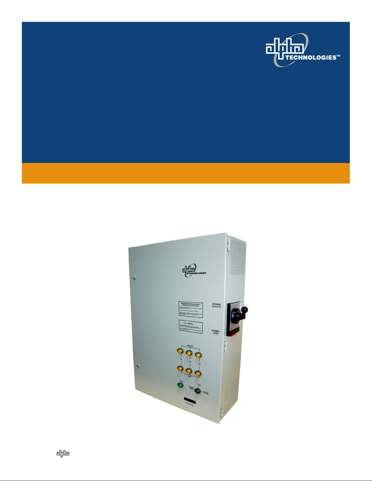
Alpha 255A External Maintenance Bypass Switch
for Uninterruptible Power Supply Systems
Installation & Operation Manual
Part # 0200018-J0
Effective: 01/2012
member of The Group
™
Your Power Solutions Partner
Page 2

Page 3

Alpha 255A External Maintenance Bypass Switch
for Uninterruptible Power Supply Systems
NOTE:
Photographs contained in this manual are for illustrative purposes only. These photographs may not match your installation.
NOTE:
Operator is cautioned to review the drawings and illustrations contained in this manual
before proceeding. If there are questions regarding the safe operation of this powering
system, contact Alpha Technologies or your nearest Alpha representative.
NOTE:
Alpha shall not be held liable for any damage or injury involving its enclosures, power
supplies, generators, batteries, or other hardware if used or operated in any manner or
subject to any condition inconsistent with its intended purpose, or if installed or operated in an unapproved manner, or improperly maintained.
For technical support, contact Alpha Technologies:
Copyright
Copyright © 2012 Alpha Technologies Ltd. All rights reserved. Alpha is a registered trademark of Alpha
Technologies.
No part of this documentation shall be reproduced, stored in a retrieval system, translated, transcribed, or
transmitted in any form or by any means manual, electric, electronic, electromechanical, chemical, optical, or otherwise without prior explicit written permission from Alpha Technologies.
This document, the software it describes, and the information and know-how they contain constitute the
proprietary, confidential and valuable trade secret information of Alpha Technologies, and may not be
used for any unauthorized purpose, or disclosed to others without the prior written permission of Alpha
Technologies.
The material contained in this document is for information only and is subject to change without notice.
While reasonable efforts have been made in the preparation of this document to assure its accuracy,
Alpha Technologies assumes no liability resulting from errors or omissions in this document, or from the
use of the information contained herein. Alpha Technologies reserves the right to make changes in the
product design without reservation and without notification to its users.
Canada and USA: 1-888-462-7487
International: +1-604-436-5547
Email: support@alpha.ca
Page 4

Table of Contents
1. Product Safety Information ...................................................................................................3
1.1 Safety Symbols .......................................................................................................................... 3
1.2 General Warning and Cautions .................................................................................................. 4
1.3 Certications and Compliances ................................................................................................. 4
2. Introduction ...........................................................................................................................5
2.1 What this Manual Covers ........................................................................................................... 5
2.2 Who Should Read this Manual .................................................................................................. 5
2.3 How to Use this Manual ............................................................................................................. 5
2.4 Symbols Used on the Product ................................................................................................... 5
2.5 Related Documents ................................................................................................................... 5
3. Features ................................................................................................................................6
3.1 Phase Detector with Lock-out .................................................................................................... 6
3.2 Auxiliary Contacts for Remote Monitoring .................................................................................. 7
3.3 Lockout with a Padlock .............................................................................................................. 8
4. Pre-Installation ......................................................................................................................9
4.1 Unpacking .................................................................................................................................. 9
4.2 Site Planning ............................................................................................................................ 10
5. Installation ........................................................................................................................... 11
5.1 Installing the Manual Bypass Handle ........................................................................................11
5.2 Wiring the Alpha MBS .............................................................................................................. 12
6. System Schematic ..............................................................................................................14
7. Operations ..........................................................................................................................15
8. Troubleshooting ..................................................................................................................16
8.1 Manual Release of Bypass Switch Solenoid ............................................................................ 16
9. Specications ......................................................................................................................17
10. Warranty ...........................................................................................................................18
2
0200018-J0 Rev C
Page 5

1. Product Safety Information
SAVE THESE INSTRUCTIONS: This manual contains important safety instruc-
tions that must be followed during the installation, servicing, and maintenance of the product. Keep it in a
safe place. Review the drawings and illustrations contained in this manual before proceeding. If there are
any questions regarding the safe installation or operation of this product, contact Alpha Technologies or
the nearest Alpha representative.
1.1 Safety Symbols
To reduce the risk of injury or death, and to ensure the continued safe operation of this product, the following symbols have been placed throughout this manual. Where these symbols appear, use extra care
and attention.
The use of ATTENTION indicates specic regulatory/code requirements that may affect the
placement of equipment and /or installation procedures.
NOTE:
A NOTE provides additional information to help complete a specic task or procedure.
Notes are designated with a check mark, the word NOTE, and a rule beneath which the
information appears.
CAUTION!
CAUTION indicates safety information intended to PREVENT DAMAGE to material or
equipment. Cautions are designated with a yellow warning triangle, the word CAUTION,
and a rule beneath which the information appears.
WARNING!
WARNING presents safety information to PREVENT INJURY OR DEATH to personnel.
Warnings are indicated by a shock hazard icon, the word WARNING, and a rule beneath
which the information appears.
0200018-J0 Rev C
3
Page 6

1.2 General Warning and Cautions
WARNING!
You must read and understand the following warnings before installing the Alpha MBS
and its components. Failure to do so could result in personal injury or death.
• Read and follow all instructions included in this manual.
• Do not work alone under hazardous conditions.
• Only qualified personnel are allowed to install, operate and service this system and its components.
• Before proceeding, read this manual and be sure you understand its intent.
• Always assume electrical connections or conductors are live. Turn off all circuit breakers and double-check with a voltmeter before performing installation or maintenance.
• Keep tools away from walk areas where you or others could fall over them.
• Wear safety glasses when working under any conditions that might be hazardous to your eyes.
• Do not work on the system, or connect, or disconnect cables during periods of lightning activity.
• If you have an installation configuration that is not described in this manual contact Alpha for assistance.
1.3 Certifications and Compliances
The Alpha MBS has been designed, manufactured, and tested to the requirements of the following national and international safety standards:
; UL 508
4
0200018-J0 Rev C
Page 7

2. Introduction
2.1 What this Manual Covers
This manual provides full procedures for the safe and proper installation and operation of the Alpha External Maintenance Bypass Switch (Alpha MBS) with meter controlled solenoid lockout.
2.2 Who Should Read this Manual
This manual is intended for qualified installers – trained electricians or technicians who are fully educated
on the hazards of installing electrical equipment such as uninterruptible power supplies and their associated batteries and accessories. The Product Safety Information chapter is intended for anyone who will
be operating the Alpha MBS as a non-technical user.
2.3 How to Use this Manual
Before you begin installing the Alpha MBS, read all the warnings and cautions described in Chapter 1.
Once you are aware of all safety issues, start planning the installation by reading Chapter "4. Pre-Installation" and Chapter "7. Operations".
2.4 Symbols Used on the Product
Risk of electric shock
2.5 Related Documents
• Local electrical codes (e.g. National Electrical Code, or NFPA 70 in the United States, Canadian
Electrical Code or CSA C22.1 in Canada)
0200018-J0 Rev C
5
Page 8
3. Features
The Alpha MBS is a manually operated mechanical switch for use with the Alpha series of Uninterruptible
Power Supplies (UPS). It provides a simple and effective means for bypassing uninterruptible power supplies (UPS) while maintaining continuity of power to critical loads. (A schematic at the end of the manual
shows the MBS with the Alpha AMPS80 HP power system.)
Normally the output to the critical load is powered by the UPS with the bypass switch in the NORMAL
(UPS) position. Before the UPS is taken off-line for service or maintenance, the bypass switch can be
switched to the BYPASS position and the critical loads then receive power directly from the utility supply.
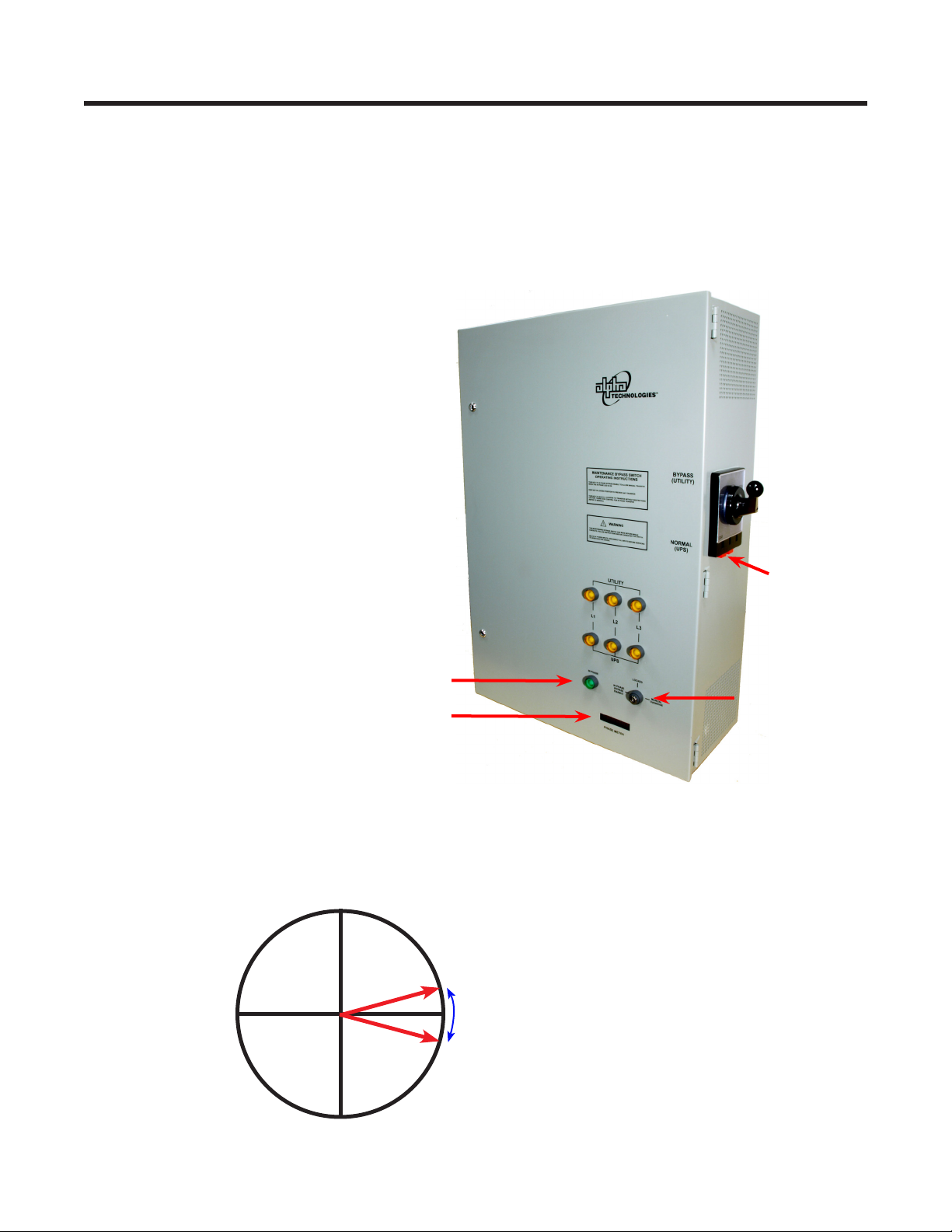
The Alpha MBS includes the following safety features:
• Phase detector with lock out
• Safe-to-switch (IN PHASE) lamp
• Electromechanical manual override
• Auxiliary contacts for remote monitoring
• Padlock bar for lockout
Manual switch
IN PHASE lamp
Phase meter
3.1 Phase Detector with Lock-out
Bypass mode is enabled when UTILITY IN is within plus or minus 15 degrees of UPS OUT. The phase
difference is displayed in the phase meter at the bottom of the front panel in the range 0-360°.
Bar for lockout
with a padlock
Electro-mechanical
key-operated switch
15°
In Phase Bypass Enabled
345°
6
0200018-J0 Rev C
Page 9

R
E
D
3.2 Auxiliary Contacts for Remote Monitoring
The operation of the Alpha MBS is "make-before-break". The auxiliary contacts are available to generate
an alarm if a "caught in transition" condition occurs.
The auxiliary switch contacts are located below TB3 in the interior of the Alpha MBS – see Figure 1.
Table A shows the condition of these contacts for all possible states of the bypass switch.
The System Schematic is shown in Chapter 6 on page 14.
A
R
Y
A
U
X
A
A
1
A
3
A
5
A
7
1
1
B
Y
P
A
3
3
N
O
R
M
4
A
5
5
*
A
7
C
L
O
*
P
O
*
7
D
B
E
T
W
S
E
IO
S
I
T
E
N
S
S
W
I
L
I
2
6
8
N
E
I
A
2
A
4
A
6
A
8
#
1
4
A
Table A — Auxiliary switch truth table
MBS Function
BYPASS A1-A2 (BYP) Closed
UPS A3-A4 (UPS) Closed
CAUGHT IN
TRANSITION
A5-A6 Closed between positions
A7-A8 Closed between positions
Figure 1 — Auxiliary contacts
H
T
C
A
2
A
4
A
6
A
8
G
W
Table B — Auxiliary Contacts – Electrical Ratings
Voltage Rating
Current Rating
0200018-J0 Rev C
250 Vac (max)
15 A
7
Page 10

3.3 Lockout with a Padlock
When someone is working on the UPS, they may want to padlock the handle in the BYPASS position to
prevent anyone changing the handle position while the work is in progress.
A padlock can be attached to the red bar at the bottom of the manual switch. Push the red bar in, and
route a padlock (or lockout bar) through the openings on the face, down toward the bottom of the legend
(Figure 2).
Figure 2 — Lockout with a padlock
8
0200018-J0 Rev C
Page 11

4. Pre-Installation
4.1 Unpacking
Before unpacking the product, note any damage to the shipping container. Unpack the product and
inspect the exterior for damage. If any damage is observed, contact the carrier immediately.
Continue the inspection for any internal damage. In the unlikely event of internal damage, inform the carrier and contact Alpha Technologies for advice on the impact of any damage:
1 888 462-7487
4.1.1 Returns for Service
Save the original shipping container. If the product needs to be returned for service, it should be packaged in its original shipping container. If the original container is unavailable, make sure that the product
is packed with at least three inches of shock-absorbing material to prevent shipping damage.
Alpha Technologies is not responsible for damage caused by improper packaging of returned products.
WARNING!
Branch Circuit Protection: The utility line connected to the input of the Alpha MBS
MUST be protected by an over-current, current limiting device that limits the short circuit current to under 5kA. The device must be certied for this use in accordance with
the local electrical code.
NOTE:
Note on Grounding: The Alpha MBS is suitable both for installation as part of the Common Bonding Network and the Isolated Bonding Network.
NOTE:
The Alpha MBS is suitable for installations in Network Telecommunication Facilities and
locations where the National Electrical Code applies.
0200018-J0 Rev C
9
Page 12

4.2 Site Planning
4.2.1 Mounting
Consult local electrical codes to determine a suitable location for mounting the Alpha MBS.
Use the dimensions in Figure 3 to wall mount the Alpha MBS with adequate clearance from the adjoining
wall.
0.50in 12.7mm X4
MOUNTING HOLES
0.75in
19.1mm
36.00in 914.4mm
609.6mm24.00in
0.75in 19.1mm
Alpha MBS Front View
0.75in
19.1mm
12.00in 304.8mm
DISTANCE TO WALL
OR EQUIPMENT
4.2.2 Wiring
10
0.75in
19.1mm
Figure 3 — Alpha MBS mounting diagram
The terminal blocks in the Alpha MBS are suitable for a single #6 AWG and up to 350 kcmil wire (minimum 75 ºC rated).
0200018-J0 Rev C
Page 13

5. Installation
WARNING!
Make sure that you have read and understood all the information given in "Product
Safety Information" on page 3.
CAUTION!
Always operate the switch with a quick continuous motion, do not hold it in mid-position.
CAUTION!
DO NOT operate the bypass switch while the UPS is in inverter mode (front display on
the UPS shows INVERTER).
CAUTION!
Operating with the inputs out of phase could cause damage to the critical loads.
5.1 Installing the Manual Bypass Handle
The unit ships with the handle sitting in the NORMAL position but
not installed (Figure 4.)
Install the handle as shown in Figure 6. The collet, the segmented
sleeve that fits around the shaft, is keyed to the shaft (Figure 5.
Take care not to rotate the handle in relation to the collet. The collet
slides on the shaft with little resistance when aligned correctly.
A raised line on the
plastic is the key
Shaft key is
corner notched
Figure 5 — Shaft and collet keying
indicator on the
collet.
Figure 4 — Shipping position
Figure 6 — Handle install sequence
0200018-J0 Rev C
11
Page 14

5.2 Wiring the Alpha MBS
WARNING!
Ensure the wire size, circuit breakers, and fuses are sized according to the applicable
electrical code and LIMIT THE SHORT CIRCUIT CURRENT TO 5000A.
WARNING!
Use minimum 75 ºC rated wire.
CAUTION!
The terminal blocks in the Alpha MBS are suitable for a single #6 AWG wire and up to
350 kcmil wire.
Alpha MBS
Utility
Utility
Over Current
current limiting
device
Over Current
current limiting
device
Disconnect
switch with
pass- through
UPS
System
UPS
System
TB2
TB1
Critical
Loads
TB3
Torque the terminal blocks to 31 N-m (275 in-lbs).
Alpha MBS
TB2
TB1
Critical
Loads
12
TB3
Figure 7 — Typical MBS wiring diagrams
0200018-J0 Rev C
Page 15

NOTE:
Phase detection is measured between TB2-L1 and TB3-L1. See the "System Schematic"
on page 14.
For a single-phase installation, ALWAYS USE L1 on all terminal blocks (TB1, TB2, TB3).
For a 2-pole installation, use L1 for one line on all terminal blocks.
Procedure
Figure 7 shows two typical configurations for wiring the Alpha MBS into an UPS system.
1. Use a #6 AWG wire and up to 350 kcmil wire (minimum 75 ºC rating) to connect the Alpha MBS and
UPS to the utility line. Refer to typical wiring diagrams in Figure 7.
2. Torque the terminal blocks to 31 N-m (275 in-lbs).
0200018-J0 Rev C
13
Page 16

6. System Schematic
2
H
C
T
I
W
S
Y
R
A
I
L
I
X
U
A
D
A
O
L
L
A
C
I
:
T
I
1
R
B
C
T
2
1
L
L
3
2
1
L
3
K
C
A
L
B
G
W
A
1
#
S
S
A
P
Y
B
M
R
O
N
1
K
L
C
1
A
L
B
G
W
A
1
#
)
A
0
z
6
H
2
0
(
6
/
M
G
0
C
5
W
M
,
A
0
D
0
1
N
5
#
U
#
C
N
I
O
A
R
V
R
W
O
0
G
T
F
:
:
4
2
:
+
R
D
/
E
E
0
E
E
L
2
Z
R
W
I
B
1
I
O
S
-
A
W
P
C
S
C
4
L
L
G
A
,
A
A
V
N
E
I
N
8
N
S
I
0
M
R
A
M
2
O
/
E
H
R
0
T
C
P
E
2
N
N
T
I
1
3
I
:
2
.
2
B
T
L
L
3
3
2
8
4
M
R
O
N
3
1
L
S
P
U
1
M
M
R
R
O
O
N
N
1
7
1
3
2
L
L
1
1
2
L
D
N
U
O
R
G
3
N
L
.
1
1
L
2
2
/
Y
:
"
3
3
L
L
P
Y
T
I
L
I
T
U
"
Y
:
"
2
2
L
L
P
Y
T
I
L
I
T
U
"
Y
"
:
1
1
L
L
P
Y
T
I
L
I
T
U
"
2
/
A
1
L
2
A
C
/
A
2
1
C
/
.
-
U
1
L
R
:
Q
-
C
3
E
Q
F
E
N
R
S
F
O
U
2
/
A
1
L
2
A
C
/
A
2
1
C
/
.
-
U
1
L
R
:
Q
-
C
2
E
Q
F
E
N
R
S
F
O
U
2
A
L
2
A
C
-
A
2
C
R
.
:
U
-
L
1
Q
Q
F
C
E
N
E
F
R
S
O
U
3
N
L
A
1
L
2
A
C
/
A
2
1
/
.C
-
U
1
L
R
:
Q
-
6
C
E
Q
F
E
N
R
S
F
O
U
2
/
A
1
L
2
A
C
/
A
2
1
C
/
.
-
U
1
L
R
:
Q
-
C
5
E
Q
F
E
N
R
S
F
O
U
2
A
L
2
A
C
-
A
2
C
R
.
:
U
-
L
4
Q
Q
F
C
E
N
E
F
R
S
O
U
:
"
Y
6
3
L
L
P
S
P
U
"
:
Y
"
5
2
L
L
P
S
P
U
"
"
Y
:
1
4
L
L
P
S
P
U
"
:
3
B
T
4
A
A
2
4
M
P
R
Y
O
B
N
1
3
1
3
A
A
2
P
Y
B
1
Y
T
I
L
I
T
U
0
6
1
P
P
Y
Y
B
B
5
9
3
2
L
L
2
2
2
1
L
3
L
L
,
D
I
2
L
1
L
S
N
C
L
E
A
6
8
A
A
G
D
W
E
A
4
R
1
#
N
E
8
6
*
5
5
A
E
W
T
E
*
S
B
N
D
O
I
E
T
I
S
7
S
O
L
O
P
C
*
7
A
N
"
R
E
F
S
N
A
R
T
G
O
T
Y
A
K
O
"
:
7
L
P
T
T
U
U
O
O
K
K
C
C
O
O
L
L
B
E
T
I
H
W
A
3
1
1
R
4
1
A
V
V
I
IN
0
G
2
M
1
L
R
:
A
E
E
N
T
T
G
O
I
O
T
S
N
2
R
R
)
O
D
T
L
E
C
E
Y
E
S
E
L
K
(
E
S
R
E
E
D
I
V
R
O
E
L
.
B
P
0
A
Y
0
B
N
E
X
O
D
N
E
S
L
K
O
C
S
O
L
S
E
N
Z
U
I
G
H
R
IC
E
H
N
W
E
3
1
4
1
D
E
R
2
1
.
E
D
D
I
K
E
Z
C
O
I
N
O
G
L
E
R
L
S
E
I
O
.
N
S
H
H
E
-
C
C
N
E
T
T
E
I
I
D
H
W
W
S
I
W
S
S
ID
C
O
D
N
V
E
0
L
2
1
O
S
A
1
:
F
.
N
R
4
G
3
X
0
0
2
R
:
S
R
E
P
M
U
J
L
E
N
N
A
H
C
L
A
U
D
R
E
e
e
e
T
n
n
n
E
o
o
o
M
E
S
A
H
P
b
n
n
n
a
4
3
2
1
0
B
B
B
/B
/
/
/
/B
4
3
2
1
0
A
A
A
A
A
2
6
3
4
5
P
S
L
D
A
L
E
N
A
I
S
R
M
S
T
R
U
U
E
B
E
T
N
S
I
T
A
N
D
N
U
O
R
G
5
1
R
1
9
D
E
R
2
3
1
M
P
P
1
5
3
2
P
1
1
:
R
.
P
U
.
P
D
A
6
4
2
L
1
L
o
t
3
3
1
-
L
1
P
:
o
.
d
t
e
C
6
-
g
S
4
n
a
E
d
h
n
D
a
C
:
1
1
E
/
4
T
2
/
A
3
D
0
:
A
.
.
V
V
E
E
R
R
.
.
.
U
.
D
t
n
e
m
e
g
n
a
r
s
r
r
a
ie
l
if
e
t
n
n
a
e
p
id
k
c
B
a
b
T
d
h
e
c
t
g
a
n
a
m
h
o
t
C
1
/1
5
/2
3
0
:
B
.
V
E
R
.
.
.
U
U
U
U
U
.
.
.
.
.
D
D
D
D
n
io
t
ip
r
c
s
.
e
N
d
/
e
P
g
a
a
lt
h
o
lp
v
A
d
t
d
e
il
g
te
u
n
a
b
a
d
s
h
p
A
C
U
1
1
1
1
1
1
/
/
/
9
9
5
2
0
/2
/
/
4
3
7
0
0
0
:
:
:
E
D
C
.
.
.
V
V
V
E
E
E
R
R
R
1
D
1
3
0
S
2
s
0
r
-
e
1
b
N
m
S
u
P
n
3
-
e
5
ir
5
d
2
l w
e
o
M
r
is
t
P
v
n
e
B
o
r
c
.
g
d
o
e
r
v
p
o
r
e
m
t
e
e
R
M
1
1
:
1
1
/
/
O
8
2
N
0
/
/1
2
0
G
1
1
N
:
:
I
F
G
W
.
.
A
V
V
E
R
E
R
R
D
1
1
/
4
/0
3
0
:
E
T
A
D
5
D
E
.
9
8
1
0
0
0
2
0
N
R
E
B
M
.
d
U
b
.
N
r
T
w
p
R
A
in
a
P
m
n
"
o
L
A
a
r
M
e
R
p
O
m
N
ju
"
e
E
v
"
o
H
K
T
m
A
e
E
N
I
R
R
N
D
I
B
-
E
D
E
S
E
R
O
S
O
L
O
F
C
B
L
E
E
C
B
-
R
E
E
A
R
K
"
A
A
M
"
M
R
P
"
6
O
Y
E
R
E
E
S
T
A
E
H
P
M
4
A
B
N
R
"
"
A
D
D
S
E
E
T
K
K
C
R
R
A
A
A
T
M
M
N
S
S
.
O
T
T
N
C
C
C
O
I
H
A
A
T
T
T
C
I
T
N
N
S
I
O
O
O
W
C
P
C
S
:
1
#
E
T
O
N
1
:
S
E
T
O
N
B
B
M
P
3
,
A
5
5
2
,
C
A
V
8
0
2
L
E
N
A
P
S
S
A
P
Y
B
D
R
A
D
N
A
T
S
N
O
I
T
N
C
O
E
I
T
T
O
P
I
R
R
P
C
T
I
S
U
E
C
D
R
I
C
H
C
N
A
R
.
B
N
D
S
IO
N
T
R
A
I
E
S
T
H
O
C
T
P
E
O
"
N
S
Y
N
S
B
O
A
D
C
P
E
S
Y
I
B
ID
D
"
V
N
E
I
O
H
A
R
P
M
T
:
2
#
E
T
O
N
2
T
U
A
.
T
R
D
O
U
P
O
R
K
O
:
C
C
N
I
L
O
L
L
A
A
V
D
N
I
O
I
O
O
T
R
A
N
N
E
P
R
L
P
E
O
T
A
N
S
I
S
D
E
E
H
L
m
C
L
o
T
I
c
.
O
s
W
e
R
S
h
T
L
1
itc
O
N
1
w
/
R
O
ls
4
T
o
0
N
r
/
t
C
O
n
3
R
o
C
0
c
.
E
y
w
T
b
w
:
S
E
w
E
I
E
M
G
T
O
H
A
L
5
1
IT
O
D
8
N
0
W
H
9
C
A
E
C
T
,
h
A
c
H
N
a
P
e
F
L
B
A
g
M
n
R
:
o
O
L
Y
.
F
e
D
B
v
E
A
R
r
N
U
a
T
M
W
C
a
A
A
ir
F
R
U
M
5
N
D
2
A
4
M
2
14
0200018-J0 Rev C
Page 17

7. Operations
CAUTION!
The NORMAL/ BYPASS switch position cannot be changed if power is not present from
either power source. The Alpha MBS operates normally if at least one power source is
present. See Table A.
CAUTION!
The MANUAL OVERRIDE key can be used to change the source selection of the Alpha
MBS even when the inputs are out-of-phase condition. Operating with the inputs out of
phase could cause damage to the critical loads.
1. To allow manual transfer, turn the lockout-key to IN PHASE BYPASS ENABLE
IN PHASE lamp
Figure 8 — In phase bypass enable
2. When the green IN PHASE lamp is illuminated, turn the
switch on the side panel (Figure 8) to BYPASS.
3. Turn the lockout-key to LOCKED to prevent inadvertent
transfer.
NOTE:
Electro-mechanical
key-operated switch
Figure 9 — Side panel NORMAL/BYPASS switch
Refer to section 3.3 to lockout the manual switch with a padlock.
0200018-J0 Rev C
15
Page 18

8. Troubleshooting
8.1 Manual Release of Bypass Switch Solenoid
WARNING!
Do NOT perform this procedure if power is present at the switch.
The NORMAL/ BYPASS switch position cannot be changed if power is not present from either power
source. Use the following procedure to release the bypass switch solenoid if a situation arises where all
power is lost and it is necessary to change the position of the switch.
1. Release the solenoid by inserting a non-conductive device (plastic pen, e.g ), into the hole in the
bottom of the switch mount.
2. Listen for the audible click of the solenoid as it releases.
3. Reposition the switch.
16
Hole in the
bottom of the
switch mount
Pen or
other nonconducting
device
Figure 10 — Manual release of bypass switch solenoid
0200018-J0 Rev C
Page 19

9. Specifications
Alpha MBS Specifications and Approvals
Model Number 0200018
Alpha MBS – Mechanical Specifications
Dimensions, cm (in)
H x W x D
Weight, kg (lb) 79.5 (175)
Color Grey
Humidity Operating (non-condensing): Up to 95%
Cooling Not applicable (no heat generating
Sound Power Level Not applicable
Temperature Range °C (°F) Operating: -20 (-4) to 40 (104)
Altitude m (ft) Operating: Up to 3658 (12,000)
91 x 61 x 28 (36 x 24 x 11)
Storage: Up to 95%
components inside)
Storage: -40 (-40) to 75 (167)
Storage: Up to 4572 (15,000)
Alpha MBS – Electrical Specifications
Voltage Rating 120/ 208 and 120/240 Vac (nominal)
Current Rating 255 A
Short Circuit Current
Rating
Current vs Temp
5kA
Current (A) Ambient Temperature
255 40°C
210 45°C
170 50°C
Alpha MBS – Auxiliary Contacts Ratings
Voltage Rating
Current Rating 20 A
Alpha MBS – Approvals
Electrical Safety
0200018-J0 Rev C
120 Vac (max)
This product is provided with the following
Product Certification marking:
UL / cUL 508 Listing Mark
17
Page 20

10. Warranty
Alpha Technologies Ltd. warrants all equipment manufactured by it to be free from defects in parts and
labor, for a period of two years from the date of shipment from the factory. The warranty provides for
repairing, replacing or issuing credit (at Alpha’s discretion) for any equipment manufactured by it and
returned by the customer to the factory or other authorized location during the warranty period. There are
limitations to this warranty coverage. The warranty does not provide to the customer or other parties any
remedies other than the above. It does not provide coverage for any loss of profits, loss of use, costs for
removal or installation of defective equipment, damages or consequential damages based upon equipment failure during or after the warranty period. No other obligations are expressed or implied. Warranty
also does not cover damage or equipment failure due to cause(s) external to the unit including, but not
limited to, environmental conditions, water damage, power surges or any other external influence.
The customer is responsible for all shipping and handling charges. Where products are covered under
warranty Alpha will pay the cost of shipping the repaired or replacement unit back to the customer.
18
0200018-J0 Rev C
Page 21

Page 22

CSA/NRTL — MARKS — BACKGROUND
What are the CSA and NRTL?
CSA (Canadian Standards Association also known as CSA International) was established in 1919 as
an independent testing laboratory in Canada. CSA received its recognition as an NRTL (Nationally
Recognized Testing Laboratory) in 1992 from OSHA (Occupational Safety and Health Administration) in
the United States of America (Docket No. NRTL-2-92). This was expanded and renewed in 1997, 1999,
and 2001. The specific notifications were posted on OSHA’s official website as follows:
Federal Register #: 59:40602 - 40609 [08/09/1994]
Federal Register #: 64:60240 - 60241 [11/04/1999]
Federal Register #: 66:35271 - 35278 [07/03/2001]
When these marks appear with the indicator “C and US” or “NRTL/C” it means that the product is
certified for both the US and Canadian markets, to the applicable US and Canadian standards. (1)
Alpha rectifier and power system products, bearing the aforementioned CSA marks, are
certified to CSA C22.2 No. 950 and UL 1950, or CSA/UL 60950.
Alpha UPS products, bearing the aforementioned CSA marks, are certified to CSA C22.2 No.
107.3 and UL 1778.
As part of the reciprocal, US/Canada agreement regarding testing laboratories, the Standards Council
of Canada (Canada’s national accreditation body) granted Underwriters Laboratories (UL) authority to
certify products for sale in Canada. (2)
Only Underwriters Laboratories may grant a licence for the use of this mark, which indicates compliance
with both Canadian and US requirements. (3)
What are NRTLs and what do they do?
NRTLs are third party organizations recognized by OSHA, US Department of Labor, under the NRTL
program.
The testing and certifications are based on product safety standards developed by US based standards
developing organizations and are often issued by the American National Standards Institute (ANSI). (4)
The NRTL determines that a product meets the requirements of an appropriate consensus-based
product safety standard either by successfully testing the product itself, or by verifying that a contract
laboratory has done so, and the NRTL certifies that the product meets the requirements of the product
safety standard. (4)
The product on which either of these marks appear
has been certified by CSA as meeting applicable
Canada/US standards.
The product on which this mark
appears has been certified by UL
as meeting applicable Canada/US
standards.
When was the NRTL started and who governs it?
In 1983, in a suit brought on by an independent testing laboratory, OSHA was court ordered to remove
specific references to UL (Underwriters Laboratories) and FMRC (Factory Mutual Research Corporation)
from its regulations.
In 1988, OSHA revised its regulations to remove those references and the NRTL program was
established.
The NRTL Program is both national and international in scope with foreign labs permitted.
References:
Information in this document has been developed from the official websites of the respective
organizations.
(1) www.csa-international.org
(2) www.scc.ca
(3) www.ulc.ca
(4) www.osha.gov
www.alpha.ca
048-554-10-I1 Rev D (2011/03)
Page 23

Page 24

Alpha Technologies Ltd.
7700 Riverfront Gate
Burnaby, BC V5J 5M4
Canada
Tel: +1 604 436 5900
Fax: +1 604 436 1233
Toll Free: +1 800 667 8743
Alpha Technologies Inc.
3767 Alpha Way
Bellingham, WA 98226
United States
Tel: +1 360 647 2360
Fax: +1 360 671 4936
Alpha Industrial Power Inc.
1075 Satellite Blvd NW,
Suite 400
Suwanee, GA 30024
United States
Tel: +1 678 475 3995
Fax: +1 678 584 9259
Alpha Energy
1628 W Williams Drive
Phoenix, AZ 85027
United States
Tel: +1 602 997 1007
Fax: +1 623 249 7833
Alpha Technologies Europe Ltd.
Twyford House Thorley
Bishop’s Stortford
Hertfordshire, CM22 7PA
United Kingdom
Tel: +44 1279 501110
Fax: +44 1279 659870
Alpha Technologies
Unit 504, 5/F,
Fourseas Building
No 208-212 Nathan Road
Kowloon, Hong Kong
Tel: +852 2736 8663
Fax: +852 2199 7988
Alpha Technologies GmbH
Hansastrasse 8
D-91126
Schwabach, Germany
Tel: +49 9122 79889 0
Fax: +49 9122 79889 21
Alphatec Ltd.
339 St. Andrews St.
Suite 101 Andrea Chambers
P.O. Box 56468
3307 Limassol, Cyprus
Tel: +357 25 375 675
Fax: +357 25 359 595
Alpha Innovations Brasil
Rua Manuel Augusto
de Alvarenga, 155
São Paulo, SP - Brasil
Tel: +55 11 2476 0150
Fax: +55 11 2476 0150
For technical support, contact Alpha Technologies:
Canada and USA: 1-888-462-7487
International: +1-604-436-5547
Technologies Argus
First de Mexico
Anatole France Num. 17
Colonia Polanco
11560, México D.F.
Tel: +52 55 5280 6990
Alpha TEK ooo
Khokhlovskiy Pereulok 16
Stroenie 1, Office 403
Moscow, 109028
Russia
Tel: +7 495 916 1854
Fax: +7 495 916 1349
Alphatec Baltic
S. Konarskio Street 49-201
Vilnius, LT-03123
Lithuania
Tel: +370 5 210 5291
Fax: +370 5 210 5292
Visit us at www.alpha.ca
Due to continuing product development, Alpha Technologies reserves the right to change specifications without notice.
Copyright © 2012 Alpha Technologies. All Rights Reserved. Alpha® is a registered trademark of Alpha Technologies.
 Loading...