

Page 1
Alpha Continuity: 6K / 10K
Indoor Double Conversion Online UPS
User Manual
Effective: 03/2011
member of The Group
™
Your Power Solutions Partner
Page 2

Page 3

Alpha Continuity: 6K / 10K
Indoor Double Conversion Online UPS
NOTE:
Photographs contained in this manual are for illustrative purposes only. These photographs may not match your installation.
NOTE:
Operator is cautioned to review the drawings and illustrations contained in this manual
before proceeding. If there are questions regarding the safe operation of this powering
system, contact Alpha Technologies or your nearest Alpha representative.
NOTE:
Alpha shall not be held liable for any damage or injury involving its enclosures, power
supplies, generators, batteries, or other hardware if used or operated in any manner or
subject to any condition inconsistent with its intended purpose, or if installed or operated in an unapproved manner, or improperly maintained.
For technical support, contact Alpha Technologies:
Copyright
Copyright © 2011 Alpha Technologies Ltd. All rights reserved. Alpha is a registered trademark of Alpha
Technologies.
No part of this documentation shall be reproduced, stored in a retrieval system, translated, transcribed, or
transmitted in any form or by any means manual, electric, electronic, electromechanical, chemical, optical, or otherwise without prior explicit written permission from Alpha Technologies.
This document, the software it describes, and the information and know-how they contain constitute the
proprietary, confidential and valuable trade secret information of Alpha Technologies, and may not be
used for any unauthorized purpose, or disclosed to others without the prior written permission of Alpha
Technologies.
The material contained in this document is for information only and is subject to change without notice.
While reasonable efforts have been made in the preparation of this document to assure its accuracy,
Alpha Technologies assumes no liability resulting from errors or omissions in this document, or from the
use of the information contained herein. Alpha Technologies reserves the right to make changes in the
product design without reservation and without notification to its users.
Canada and USA: 1-888-462-7487
International: +1-604-436-5547
Email: support@alpha.ca
Page 4

Table of Contents
1. Important Safety Instructions ................................................................................................3
1.1 Important Information ........................................................................................................... 3
1.2 Storage Instruction ............................................................................................................... 4
2. Introduction ...........................................................................................................................5
2.1 General Characteristics ........................................................................................................ 5
2.2 Optional Congurations ........................................................................................................ 6
2.3 System Block Diagram ......................................................................................................... 6
2.4 Symbols on the LCD Display Panel .................................................................................... 7
2.5 Front and Rear Panels ......................................................................................................... 9
2.6 Communication Ports ..........................................................................................................11
3. Installation and Operation ...................................................................................................12
3.1 Unpacking .......................................................................................................................... 12
3.2 Selecting Installation Position ........................................................................................... 13
3.3 Installation of the Accessory kits ........................................................................................ 14
3.4 Terminal Block Wiring ......................................................................................................... 15
3.5 Operation Test and Installation Instruction ......................................................................... 17
4. Troubleshooting Guide ........................................................................................................27
5. Bundled Software Installation Guide ...................................................................................28
5.1 Hardware Installation ......................................................................................................... 28
5.2 Software Installation ........................................................................................................... 28
6. Optional Communication Cards ..........................................................................................29
6.1 R2E (2nd RS-232 ) Card .................................................................................................... 29
6.3 RSE (RS-485) Card ........................................................................................................... 29
6.2 USE (USB) Card ................................................................................................................ 29
6.4 DCE (Dry Contact) -B Card ................................................................................................ 30
6.5 SNMP Cards ...................................................................................................................... 30
6.6 Interface Card Installation .................................................................................................. 31
7. Specications ......................................................................................................................32
8. Warranty and Service Information ......................................................................................34
Appendix A - Transformer Installation ........................................................................................35
Appendix B - Parallel Installation ...............................................................................................41
2
0170012-J0 Rev A
Page 5

1. Important Safety Instructions
1.1 Important Information
SAVE THESE INSTRUCTIONS – This manual contains important instructions that must be followed during
the installation and maintenance of the UPS and batteries.
• The UPS has its own external energy source (battery). A voltage may be present at the output
terminals even when no AC input power is available.
• This UPS is equipped with an EMI filter. To prevent potential leakage current hazard, ensure that the
AC main supply is securely grounded.
• Make sure that the AC utility outlet is correctly grounded.
• Make sure that the input voltage to the UPS matches the rating on its name plate. Use a certified
input power cable with the correct plugs and sockets for the appropriate voltage system.
• Install the UPS indoors only as it is not designed for outdoor use. Install in a temperature-controlled
indoor area free of conductive contaminants
• To prevent the UPS from overheating, keep all ventilation openings unobstructed. Do not place
anything on top of the UPS. Keep the UPS rear panel at least 20 cm away from the wall or other
objects.
• Units are considered acceptable for use in a maximum ambient of 40°C. Make sure the UPS is installed in an appropriate environment—0 to 40ºC (32 to 104ºF) ambient temperature, and 30 to 90%
relative humidity (non-condensing).
• Do not install the UPS in direct sunlight. Failure of the batteries under these conditions may void the
warranty.
• Do not install in a inflammable or hazardous environment.
• Dusty, corrosive, or salty environments can damage the UPS.
• Install the UPS away from objects that give off excessive heat and areas that are excessively wet.
• Do not install the UPS in an environment with sparks, smoke or gas. Not for use in a computer room
as defined in the Standard for the Protection of Electronic Computer/Data processing Equipment,
ANSI/NFPA 75.
• The entrance of liquids or foreign objects into the UPS will void the warranty.
• The external battery will gradually discharge if the system is unused for extended periods.
• If unused, recharge the external battery pack every 2 to 3 months. Neglecting to do so will void the
warranty. The batteries charge automatically and are kept in good condition if the UPS is installed
and used.
• A battery can present a risk of electrical shock and high short circuit current. Observe the following
precautions when working on batteries:
a. Remove watches, rings, or other metal objects.
b. Use tools with insulated handles.
c. Wear rubber gloves and boots.
d. Do not lay tools or metal parts on top of batteries.
e. Disconnect charging source prior to connecting or disconnecting battery terminals.
f. Determine if the battery is inadvertently grounded. If inadvertently grounded, remove source from
ground. Contact with any part of a grounded battery can result in electrical shock. The likelihood
of such shock can be reduced if such grounds are removed during installation and maintenance
(applicable to equipment and remote battery supplies not having a grounded supply circuit).
0170012-J0 Rev A
3
Page 6

• There is a risk of explosion if a battery is replaced by an incorrect type.
• Do not dispose of batteries in a fire—the batteries may explode. Dispose of used batteries according to the battery manufacturer's instructions.
• Do not open or mutilate batteries. Released electrolyte is harmful to the skin and eyes. It may be
toxic.
• This UPS supports electronic equipment in offices, telecommunications, process control, medical
and security applications. Only authorized personnel must install the UPS in the following locations:
a. Medical applications directly related to human life
b. Elevators, metro (subway) system or any other equipment related to human safety
c. Public security system or critical computer systems
• Always switch off the UPS and disconnect the batteries before relocating the UPS. It may cause
electrical shocks if the output is not completely switched off.
• Do not open the UPS—there are no serviceable parts inside. Opening the UPS will void the warranty.
• Do not repair the UPS yourself Contact your local supplier. Opening the UPS will void the warranty.
• The UPS can be equipped with an optional Maintenance Bypass Switch. Follow the procedures
strictly to switch on/off the Maintenance Bypass Switch.
• The UPS offers CVCF (Constant Voltage Constant Frequency) setting function.
a. For correct setting and wiring, contact the Alpha technical service team (see chapter 8).
b. Do not do it yourself; otherwise, your warranty will be void.
• This UPS has been designed and constructed to protect your assets from the wide range of power
aberrations experienced on Utility power lines today. It is your insurance for reliable, clean and
stable voltage supply. It is worth taking care to install the system correctly and to have it maintained
correctly by your regional Alpha service center (see chapter 8).
CAUTION!
Disconnection Device - The customer must provide a disconnect switch for the AC
output circuit. To reduce the risk of re, connect only to a circuit provided with branch
circuit over-current protection of 30 amperes for 6KVA and 40 amperes for 10KVA rating
in accordance with the National Electric Code, ANSI/NFPA 70. (See details in the following table.)
CAUTION!
To reduce the risk of re, connect the unit input only to a circuit provided with branch
circuit over-current protection of 40A for 6KVA and 65A for 10KVA amperes rating in accordance with the National Electric Code, ANSI/NFPA 70.
1.2 Storage Instruction
Store the UPS in a location where the temperature ranges between -15ºC (+5ºF) to 40ºC (104ºF).
For extended storage in moderate climates, charge the external battery pack for 12 hours every 3
months. Repeat every 2 months if the ambient storage temperature is above 30ºC (86ºF).
4
0170012-J0 Rev A
Page 7

2. Introduction
2.1 General Characteristics
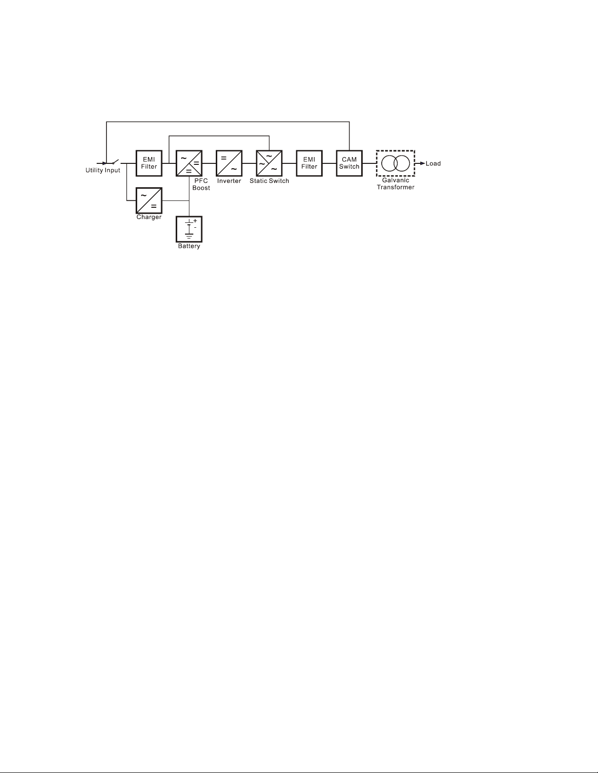
• The UPS continuously supplies your critical device with stable, regulated, transient-free pure sine
wave AC power.
• High-efficiency 20 kHz pulse-width modulation (PWM) sine-wave topology yields an excellent overall
performance. The output is capable of handling high crest factor and high inrush current loads.
• A multi-functional LCD/LED panel displays the status of the UPS. The LED display shows the UPS
working status, utility power status, and abnormal UPS status. The LCD display shows the input/output voltage, frequency, load status, inner cabinet temperature, and abnormal conditions.
• Automatic overload protection switches the output from inverter mode to bypass mode if the load
increases to between 105 and 120% of full load for 30 seconds and automatically enables inverter
mode when the overload condition is removed. If the load reaches 150% of the rated capacity, the
UPS switches to the bypass mode immediately.
• If the output is short-circuited, the UPS locks automatically, provides visual & audible alarms and
cuts the output supply until the short circuit situation is resolved.
• If the unit overheats, the internal thermal switch detects the temperature and switches to bypass
mode. It switches back to the inverter mode once the temperature drops to a predetermined value.
• This UPS is equipped with fully digitized control logic for greater functionality and an enhanced high
level of power protection. Digital signal processing (DSP) enhances the UPS communication capability by providing the flexibility for easy remote control and monitoring.
• A maintenance-free, sealed-type battery minimizes after-sales service.
• An optional maintenance bypass switch provides easy and safe troubleshooting or maintenance
when the utility power is normal.
• Four different working modes are provided that can be used for a variety of applications:
a. Normal (On-line mode)
b. ECO (Economic mode)
c. CF50 (50Hz Frequency Converter mode)
d. CF60 (60Hz Frequency Converter mode)
• When the UPS is operated in the CF50 or CF60 mode, the recommended load must be 75% of the
rated capacity if the input voltage is 176 to 280 VAC, and 50% of the rated capacity if the input voltage is 160 to 280 VAC.
• A DC-start function ensures that the UPS starts up during power outages.
• Revolutionary battery management circuit analyzes battery discharging status to adjust the battery
cut-off point and extend the batteries’ life span.
• An intelligent temperature-controlled fan extends the life of the fan, and also reduces annoying noise
caused by the sudden acceleration of the fan.
• If the UPS is out of order, a fault message will be displayed on the LCD screen.
0170012-J0 Rev A
5
Page 8
2.2 Optional Configurations
The Continuity 6K / 10K UPS can be installed with a transformer—see Appendix A.
It can also be installed in the parallel configuration—see Appendix B.
2.3 System Block Diagram
6
0170012-J0 Rev A
Page 9
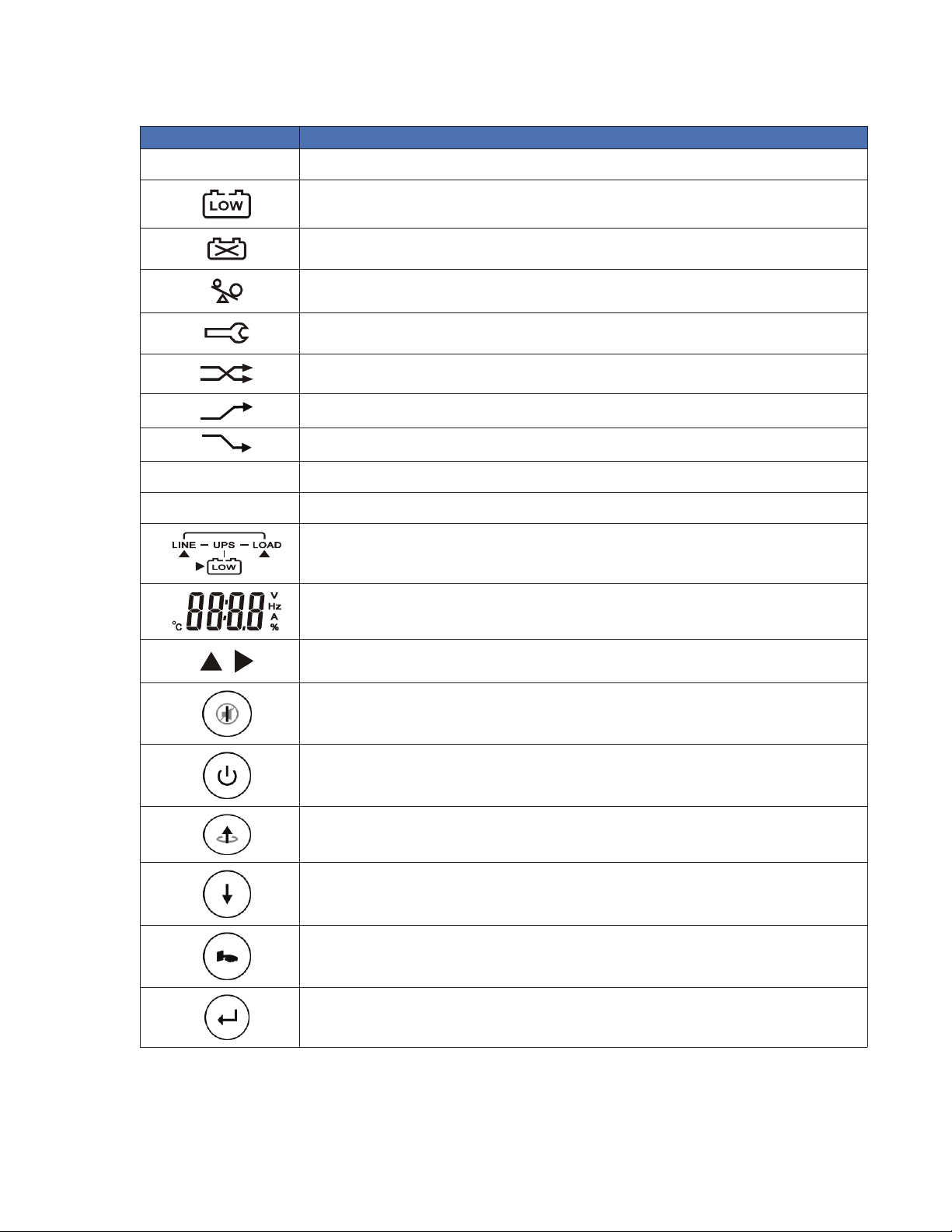
2.4 Symbols on the LCD Display Panel
Symbols Description
LINE
Utility or bypass source
OFF
FAIL
Battery low
Battery abnormal
UPS overload
UPS working in specied mode*
A blackout transfer occurred in UPS output
Bypass input abnormal. UPS fails to transfer to bypass. Bypass abnormal at ECO mode
Utility input abnormal
UPS shutoff
UPS abnormal lock
UPS ow chart
4 digit display
Indicates the desired item to be measured
UPS ON switch or alarm silence
UPS OFF switch
Previous page or setting change
Next page
Special function log in /out
Enter or reconrm
0170012-J0 Rev A
7
Page 10

Symbols Description
Utility input normal LED
Bypass input normal LED
UPS under redundancy mode
UPS under ECO mode
UPS fault or abnormal warning LED
EPO
Er05
Er06
Er10
Er11
Er12
Er14
Er15
Er16
Er17
Er21
Er24
Er27
Er28
Er31
Emergency power off
Battery weak or dead
Output short circuit
Inverter over-current
UPS overheating
UPS output overload
Fan error
Wrong procedure to enter maintenance mode
Output parameters set error in parallel system
ID numbers in conict in parallel system or ID number error in single unit
Parallel communication error. Communication wire disconnected or failure to nd ID1
UPS) in parallel system.
CVCF mode with bypass input.
The UPS must be operated in normal mode in parallel system.
Bypass overload time out and cut off output
The settings of the control board and driver board do not match.
Er33
Er**
*The specified modes include Normal mode, ECO mode, CVCF mode, etc.
8
Isolated transformer overheat
Other error code
0170012-J0 Rev A
Page 11
2.5 Front and Rear Panels
1
3 4 2 11 12
5
9
1078
6
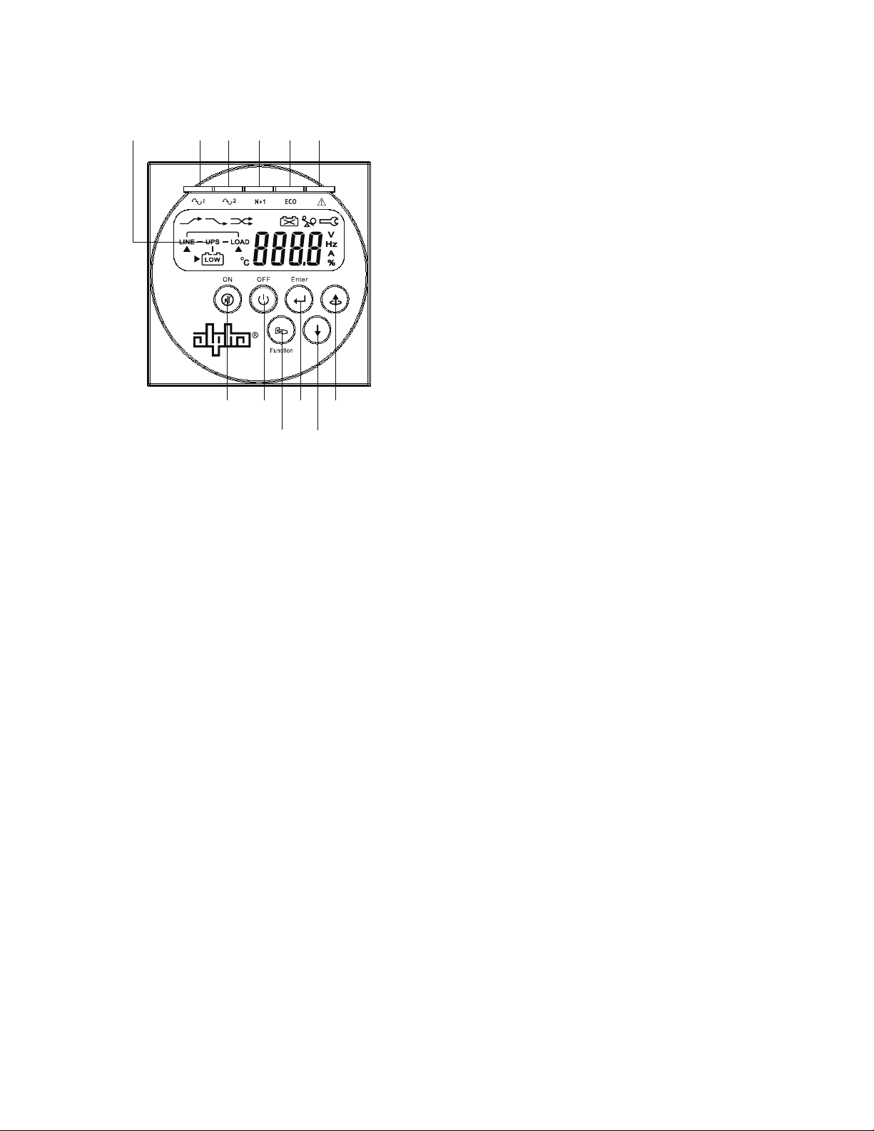
2.5.1 Front Panel Functions
1. LCD display
2. Green LED illuminates to indicate that the UPS has the capability to run under the redundancy mode.
3. Green LED illuminates to indicate that the utility input voltage is within the acceptable range.
4. Green LED illuminates to indicate the bypass input is normal.
5. UPS ON/Alarm Silence
6. Go to previous page or change the settings of the UPS
7. Re-confirm the change of UPS Setting
8. Go to the next page
9. UPS OFF switch
10. Special functions log in/out
11. UPS is working in the ECO (economic) mode
12. UPS fault or abnormal condition
0170012-J0 Rev A
9
Page 12
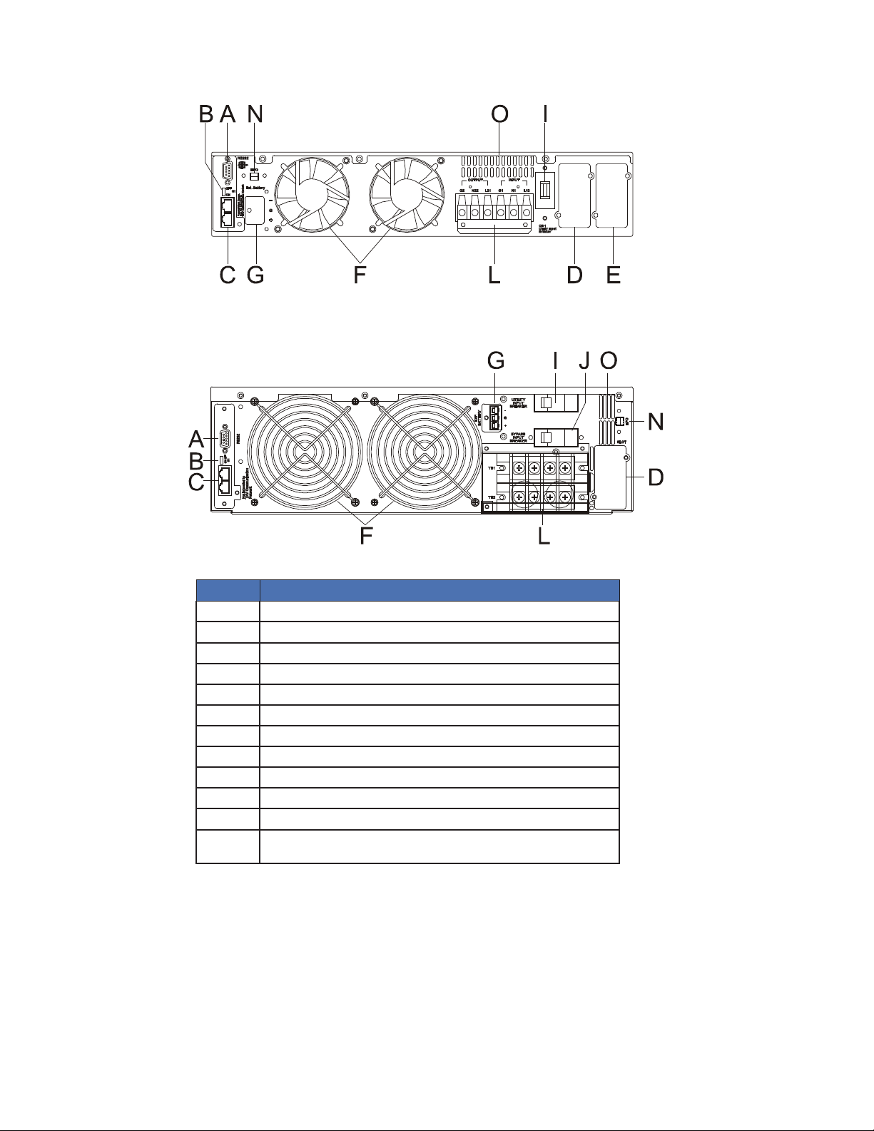
2.5.2 Rear Panel Functions
Continuity 6K
Continuity 10K
Item
A RS232 port
B Terminal resistor for parallel function
C CAN bus connection port for parallel system
D Customer options – Slot 1
E Customer options – Slot 2
F Cooling fan
G External battery connector
I Utility input breaker CB1
J Bypass input breaker CB2 for dual input model only
L Input/output terminal block
N EPO emergency power off → short to enable the function
O Thermal breaker for the protection of load during abnormal
conditions: CB3
Figure 1 — Rear Panel Components
Description
10
0170012-J0 Rev A
Page 13

2.6 Communication Ports
The UPS is equipped with a remote emergency power off (REPO) dry contact input, true RS232 and
USB communication ports to provide communication with bundled UPS monitoring software for remote
monitoring of UPS status via a PC.
Four optional interface cards are available to meet various communication needs (refer to Section 6):
• DCE (dry contact relay card)
• RS232
• USB
• SNMP/WEB card
The bundled software of the UPS is compatible with many operating systems such as Windows 98, 2000,
ME, NT and XP.
All communication ports (including optional cards) can be active simultaneously to monitor the UPS status. However only 1 communication interface can be active at any one time. The interface with the highest priority controls the UPS. The priority of these communication interfaces are as follows from highest to
lowest priority:
• REPO input port
• Optional Interface card
• USB
• RS232
The communication port on the UPS provides true RS232 type communication with the UPS software.
This is used for remote monitoring the power and UPS status.
Optional interfaces cards include R2E (2nd RS232), RSE (RS485), USE (USB), DCE (dry contact), and
SNMP/. These can be combined according to your requirements. However, the R2E, RSE, and USE card
cannot be used simultaneously.
The bundled software of the UPS is compatible with many operating systems such as Windows 98, &
2000, ME, NT and XP. For other applications like Novell, NetWare, Unix, Linux, contact your local distributor for advice.
When optional interface cards are used together with the onboard RS232 port for communications. The
REPO signals have the highest control command priority followed by the SNMP/WEB card, the shutdown
command at the DCE card and the R2E, RSE and USE cards. The onboard RS232 port has the lowest
priority.
2.6.1 True RS232 Port Settings
The RS232 interface should be set as follows:
Baud Rate: 2400 bps
Data Length: 8 bits
Stop Bit: 1 bit
Parity: None
2.6.2 USB Port Settings
The USB communication protocol definition complies with:
• USB version 1.0, 1.5 Mbps
• USB HID Version 1.0
0170012-J0 Rev A
11
Page 14
3. Installation and Operation
Read Section 1 (Important Safety Instructions) before installing the UPS
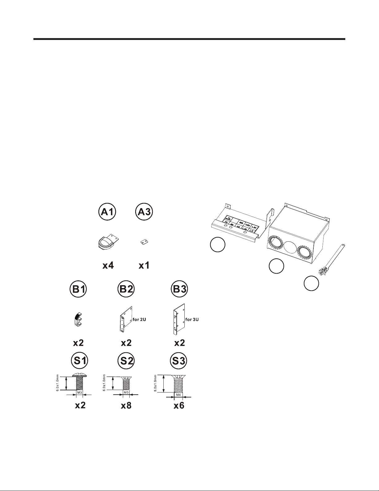
3.1 Unpacking
Inspect the UPS upon receipt. The manufacturer has designed robust packaging for your product, but
accidents and damage can occur during shipment. Notify the shipper and dealer if there is damage.
The packaging is recyclable; save it for reuse or dispose of it properly.
Remove the UPS from the cardboard box. Check that the following standard contents are included:
• One (1) user manual
• UPS communication software CD with RS232 cable
• Accessories shown below for Continuity 6K or Continuity 10K model
• Additional 1 piece of wire for a UPS with dual input but no isolation transformer (#8 for 6kVA and #6
for 10kVA).
(Note: Wire is used at the input/output terminal block of the UPS.
All Continuity models
Continuity 10K only
X1A1
X1A2
X2A3
12
(10K x 5)
0170012-J0 Rev A
Page 15
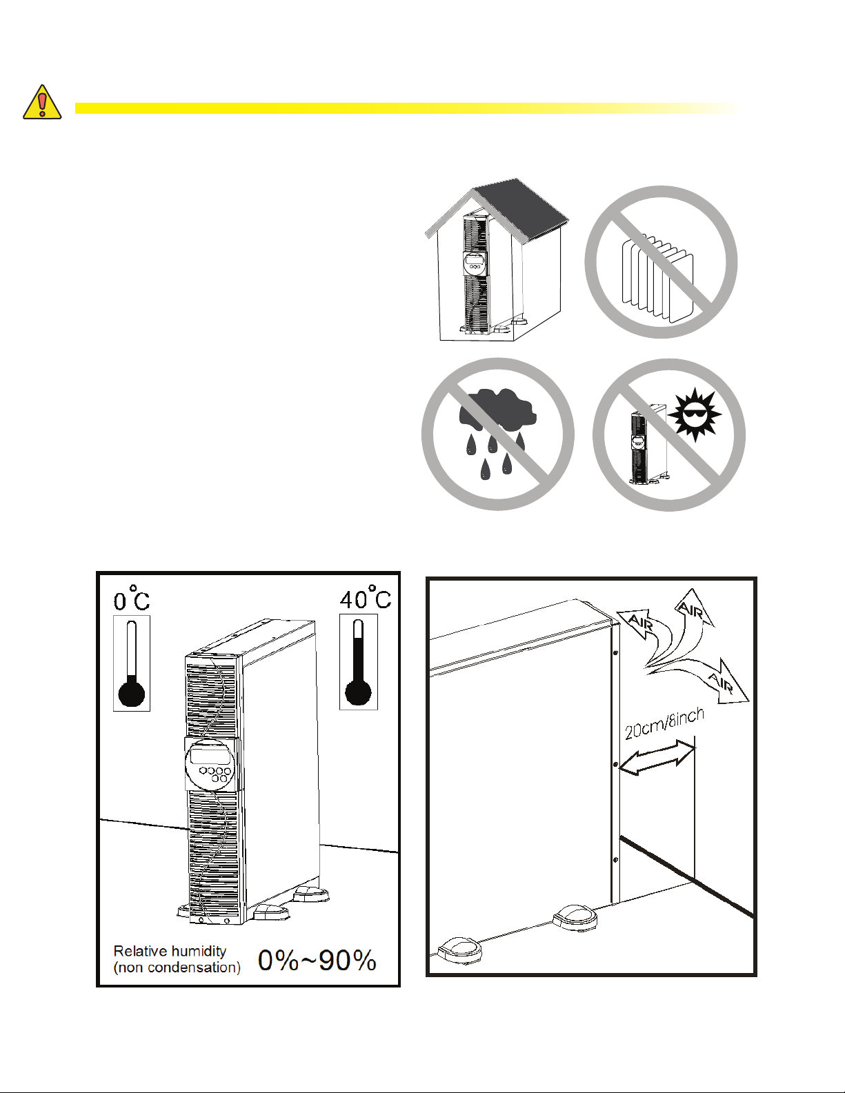
3.2 Selecting Installation Position
WARNING!
The UPS is heavy. Select a location that is structurally strong enough to withstand the
UPS weight.
To ensure proper operation and a long
operating life, position the UPS according
to the following requirements:
1. Ensure that there is a minimum of 30 cm
(12 inches) of clearance behind the rear
panel of the UPS.
2. Do not block the air-flow to the ventilation
louvers of the unit.
3. Ensure that the installation site is free
from excessive dust and that the ambient
temperature and humidity are within the
specified limits.
4. Do not place the UPS in a dusty or
corrosive environment or near flammable
objects.
5. This UPS is not designed for outdoor use.
0170012-J0 Rev A
13
Page 16
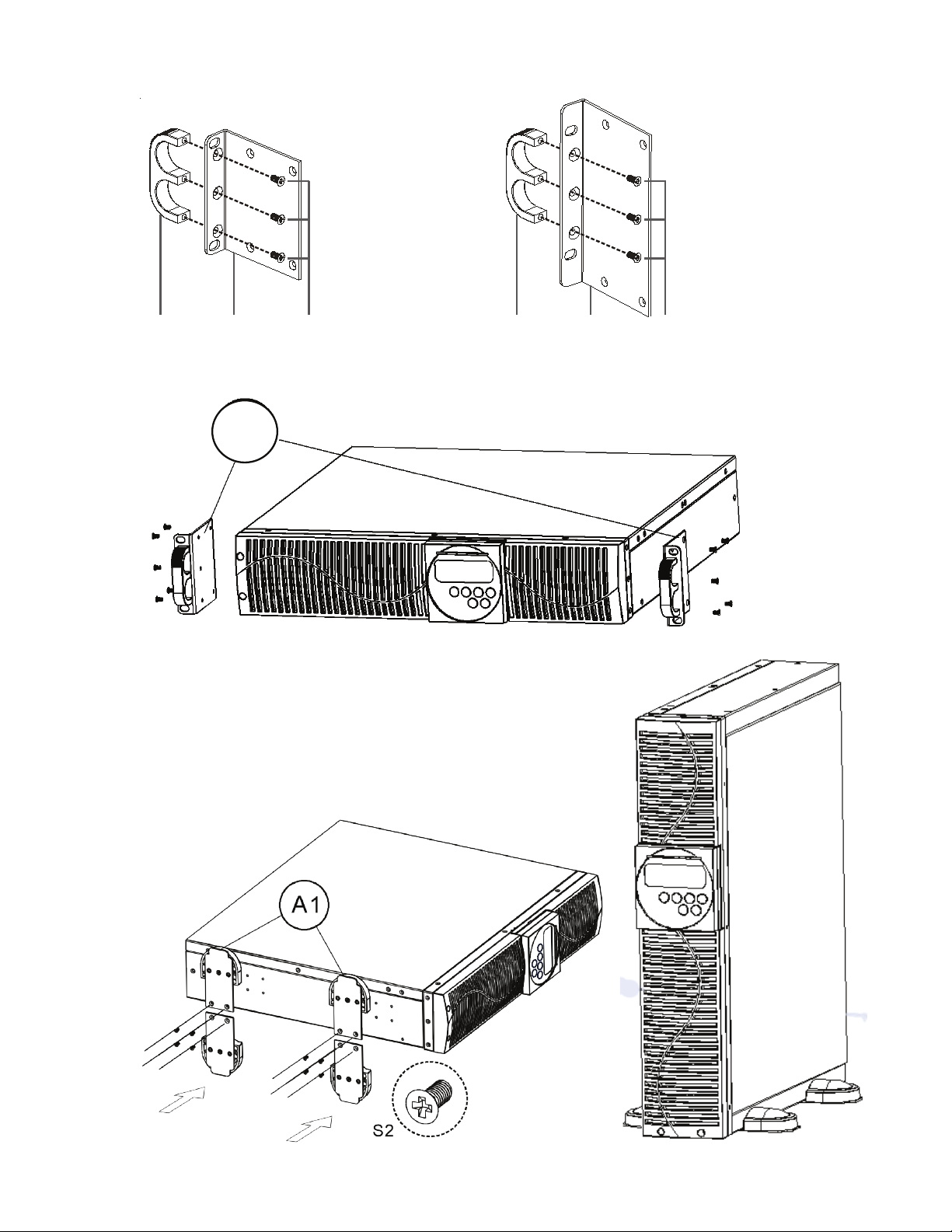
3.3 Installation of the Accessory kits
B1 B2 S3 B1 B2 S3
B2
S2
S2
14
0170012-J0 Rev A
Page 17

3.4 Terminal Block Wiring
Continuity 6K model
Continuity 10K model
TB1
TB2
Figure 2 — 1-phase terminal block wiring
L11-N1:
L12-N1
G1:
L21 ~ N22:
G2:
Terminals for bypass input that provides power to the
loads when the UPS is working in the bypass mode.
Terminals for the utility input that provides power to the
loads when the UPS is in the Utility mode.
Terminal for the UPS input ground.
Terminals for the UPS output.
Terminal for the UPS output ground.
Remarks:
• The maximum output current for each terminal is 30 Amps for the 6 kVA model and 50 Amps for the
10 kVA model.
• If the UPS is a DIM (dual input mode) type whose utility and bypass sources are the same, L11 and
L12 must to be shorted for 1-phase input models.
• If the UPS is a SIM (single input mode) type, only the AC source can be hooked up to the UPS via
the L12-N1 terminal for a 1-phase input model.
• Use cable ties to secure the cables.
0170012-J0 Rev A
15
Page 18

Continuity 6K model
Continuity 10K model
16
Refer to the table below for input current, output current, and recommended conductors specifications:
• AC input and output (75°C minimum copper wire)
Model Maximum current Conductor section Torque
6 kVA 33 A AWG #8
10 kVA 54.3 A AWG #6 23 in-lb
• Battery input
Model Maximum current Conductor section
6 kVA 25 A AWG #8
10 kVA 41 A AWG #6
0170012-J0 Rev A
Page 19

3.5 Operation Test and Installation Instruction
3.5.1 Start Up in Normal Mode
1. Open the terminal block cover on the rear panel (refer to Section 3.4). Make sure the grounding is
properly connected.
2. Make sure the utility breaker, UPS utility breaker, and Bypass breaker are in the Off position.
3. Make sure the utility voltage is within the allowable input voltage range of the UPS.
4. Connect the utility power separately to the terminal blocks of the UPS utility input and the bypass input.
5. Switch on the distribution panel breaker and the UPS utility and bypass input breakers.
6. The UPS starts up.
The green
LCD display, with parallel function, scrolls from Screen A1 to Screen B. Otherwise the LCD display scrolls
from Screen A2 to Screen B.
7. The UPS is in the bypass mode and automatically runs a self-test. If no fault messages appear, the prestartup of the UPS has been successful and the charger starts charging the batteries.
Screen A1
and LEDs illuminate indicating that the utility and bypass inputs are normal. The
Screen A2
Screen B
0170012-J0 Rev A
17
Page 20

8. Press and hold the UPS On button for approximately 3 seconds. The buzzer sounds twice and the
LCD display scrolls from Screen B to Screen C.
Screen C
9. The UPS is in self-test mode again. The LCD display scrolls from Screen C to Screen D and remains in
the battery mode for approximately 4 seconds. The display scrolls from Screen E1 to Screen F if the selftest is successful.
Screen D
Test
Screen E1
Screen E2
Screen F
OK in self test
If the self-test fails, the LCD
display scrolls from Screen D to
Screen E2. An error code or status is shown on the screen
220 VAC in utility input
18
10. The UPS start-up operation is now complete. Charge the batteries for at least 8 hours to ensure they are
fully charged.
0170012-J0 Rev A
Page 21

3.5.2 Start-up in Battery Mode (Cold Start)
1. Make sure the UPS has at least 1 set (20 pcs) of 12 V / 7 Ah batteries installed.
2. Press and hold the UPS On
display scrolls from Screen A to Screen G.
3. Press and hold the UPS On
Screen G to Screen H. The UPS is in the self-test mode and can supply power to the output after about a
minute. The LCD display will scroll to Screen I.
If a failure occurs within 15 seconds of pushing the UPS On button, the UPS will automatically switch off.
Screen G
Screen H1
button for approximately 5 seconds. The buzzer sounds twice. The LCD
button again for about 3 seconds until the LCD display scrolls from
Off means the UPS pre-start has
been successful.
Utility input is 0 and abnormal.
Screen H2
0170012-J0 Rev A
19
Page 22

3.5.3 Check Measured Values & Figures detected by UPS
Use the and keys to check the measured values and figures detected by the UPS. The LCD
display will scroll through the following screens: Screen C (Voltage from Utility Input) → Screen I (Voltage from Bypass Input) → Screen J (Frequency from Utility Input) → Screen K (Frequency from Bypass
Input) → Screen L (UPS Output Voltage) → Screen M(UPS Output Frequency) → Screen N (UPS Output
Load %) → Screen O (UPS Battery Voltage) → Screen P (UPS Inner Temperature).
Screen I
Voltage from bypass input
Screen J
Frequency from utility input.
Screen K
Screen L
Screen M
Frequency from bypass input.
UPS output voltage.
UPS output frequency.
20
0170012-J0 Rev A
Page 23

Screen N
Screen O
Screen P
Output load level (%).
Battery voltage.
UPS inner temperature.
3.5.4 UPS Default Data and Special Function Execution
1. To run a self test or check default data, press the Special function key to scroll to Screen Q1.
Screen Q1
Buzzer on.
Screen Q2
0170012-J0 Rev A
Buzzer off.
21
Page 24

2. Press the key to scroll through the UPS settings. The LCD display will sequentially show Screen Q1
(buzzer) → Screen R1 (self-test) → Screen S1 (bypass voltage ranges) → Screen T (output frequency
synchronization range) → Screen U (Inverter output voltage) → Screen V1 (UPS operation mode) →
Screen W (output voltage micro tune value) → Screen X (UPS Id) → Screen Y (parallel function status).
Screen R1
Self-test is NOT on.
Screen R2
Self-test is on.
Screen S1
Screen S2
Bypass voltage is adjusted
to a narrow range.
Bypass voltage is adjusted to a
wider range.
22
0170012-J0 Rev A
Page 25

Screen T
Screen U
Screen V1
Frequency range is +/-3 Hz.
Inverter output voltage.
UPS is in normal mode.
Screen V2
Screen V3
Screen V4
UPS is operated in Eco mode.
UPS is operated in CVCF 50 Hz mode.
0170012-J0 Rev A
UPS is operated in CVCF 60 Hz mode.
23
Page 26

Screen W
Screen X
Screen Y
Output voltage adjustment %
from 0% to 3% or -0% to -3%.
Identification number.
UPS is in the Number 1
parallel system.
3. Press the key to execute special functions. The functions include Screen Q1 (buzzer ON), Screen Q2,
alarm silence for UPS warning (buzzer OFF), Screen R1 (self-test OFF), Screen R2 (self-test ON). The
UPS will execute a battery test for 10 seconds. Screen E1 will be displayed if the self-test is successful. If
the self-test fails, Screen E2 and an error message will be displayed.
24
0170012-J0 Rev A
Page 27

3.5.5 UPS Default Settings and Alternatives
1. Press and hold the OFF button for 5 seconds. The inverter output switches off and the output load is
then supplied by the bypass loop. The LCD displays Screen B.
2. Simultaneously press and hold the ON
seconds. The buzzer sounds twice and the LCD display shows Screen Q1.
The UPS is now in setup mode. Except for the buzzer (screens Q1 and Q2) and self-test (screens R1 and R2)
settings, all default settings can be changed by pressing the Scroll Up
3. Screens S1 and S2 show the acceptable range for the input bypass voltage. Acceptable values are 184
to 260 VAC or 195 to 260 VAC.
4. Screen T shows the bypass frequency range of the inverter output. Acceptable values are ±3 Hz or ±1
Hz.
5. Screen U shows acceptable inverter output voltages. The voltage can be set to 200, 208, 220, 230, or
240 VAC.
6. Screen V1, V2, V3 and V4 show the operation modes of the UPS. The available modes are: (1) Online, (2)
Eco (Economic), (3) Fixed 50Hz Output, and (4) Fixed 60Hz Output.
7. Screen W shows the inverter output settings, which can be set to 0%, +1%, -1%, +2%, -2%, +3%, or
-3%.
8. Screen X shows the address and position of the UPS when the UPS is in the parallel mode. The values
can be set from 1st to 4th. The value must be set to 1st if the UPS is not in parallel.
9. Screen Y shows the parallel function status. P 01 means the parallel function disabled and P 02 means
the parallel function is enabled.
button and the Scroll Down key for approximately 3
key.
10. When all the changes have been completed, scroll to Screen Z and press Enter
changes. The LCD display will scroll to Screen AA, which means that the setting changes have been
completed. To cancel all the changes, press OFF
Screen AA, indicating that all the changes are invalid.
Screen Z
Screen AA
11. Switch the UPS OFF and ON (with utility input breaker CB1—Figure 1) to exit Configuration mode after all
settings are complete.
for 5 seconds. The LCD display will scroll directly to
Press Enter to save data.
UPS is locked.
to save all the
12. Your setting changes are now complete.
0170012-J0 Rev A
25
Page 28

3.5.6 Troubleshooting a UPS that is Off for an Unknown Reasons
1. If a serious abnormal condition has occurred, the UPS will lock into the OFF position. The LCD displays
Screen AA and an error message.
2. After 3 seconds, all messages are blocked except the bypass indicators: LED
utility voltage is outside the normal range after the UPS is locked, the LED
LCD
3. Unlock the UPS as follows:
will be shown on the LCD.
a. Check all the recorded error messages.
b. Check the table in Section 2.2 to troubleshoot the problem. If this is unsuccessful, consult your
local distributor for service.
c. Press and hold the OFF
d. Switch off the utility input power breaker.
e. The UPS is now unlocked, but you may want to contact your local distributor to make sure the
underlying fault has been solved.
button for 5 seconds. The buzzer sounds twice.
and LCD
will extinguish and the
3.5.7 Shutting Off the UPS
1. Press and hold the OFF button for 5 seconds. The inverter output switches off. The output load is
then supplied via the bypass loop. The LCD displays Screen B.
2. Switch off the utility input power breaker and the bypass input power breaker.
3. The UPS is now completely shut off.
. If the
3.5.8 Maintenance Bypass Mode - for Optional Maintenance Bypass Switch
The maintenance bypass mode is for UPS maintenance only. Only authorized technicians should implement this procedure. Your warranty will be void if the UPS is damaged by unauthorized repairs.
CAUTION!
Complete Step 1 before proceeding to Step 2. Otherwise the UPS will go through a 10
second warning procedure to alert you that the procedure is not being followed, which
can damage the UPS because of the uncertain utility status. The UPS will switch back to
inverter mode immediately if the CAM switch is turned back to the UPS position.
1. Press and hold the OFF
the bypass mode.
2. Remove the cover of the maintenance bypass switch (CAM switch). Turn the CAM switch to the Bypass
mode. The upper right-hand corner of the LCD display screen shows .
3. Switch off the utility input power breaker and the bypass input power breaker (see Figure 1). The UPS
can now be serviced or repaired.
4. When the repair is complete, switch on the utility input power breaker and the bypass input power
breaker.
5. The UPS starts up in the bypass mode and automatically runs a self-test. If no fault messages appear,
the pre-startup of the UPS has been successful and the charger starts charging the batteries.
button for 5 seconds. The LCD displays Screen B and the UPS output is in
6. Turn the CAM switch back to the INV/UPS position and replace the maintenance bypass switch cover.
7. Complete Steps 8 and 9 of section 3.5.1. The UPS start-up operation is now complete.
26
0170012-J0 Rev A
Page 29

4. Troubleshooting Guide
Check the following if the UPS malfunctions during operation:
• Are the input and output cables correctly connected?
• Is the utility input voltage within the allowable limits?
If the problems or symptoms persist, follow the instructions in the table below. If necessary, contact your
local distributor for help.
Problem
UPS Red Fault LED
illuminates.
UPS fails to provide
battery backup or
the back up time is
shorter than its design
performance.
UPS locks itself and
cannot be turned off.
Check Items Solution
Check that the batteries are properly connected, re-charge
Er05,
Er06, Er10, Er12, Er28,
EPO Remove the short circuit that occurred at the EPO terminal.
Er11, Er33 Remove objects that block the ventilation holes.
Er14
Er15
Er16, Er27
Er21 Reconnect the RJ-45 wire or set the UPS to ID=1.
Er24
Other error codes Consult your local dealer for assistance.
and
the batteries for 8 hours, and then check if the UPS backs
up normally. If necessary, contact your local dealer for
assistance.
If the CB3 is tripped, switch off the UPS completely. Keep the
CAM switch at the INV position and then press CB3. Remove
one non-critical UPS output load. If the coating of the AC
power cord is damaged, replace it with a new one.
Check that the cooling fans on the rear panel are working
normally.
Make sure the UPS is in the normal mode. If it is running in
the CVCF mode, switch the UPS off and then on again.
All of the settings except the ID Number must be the same in
the parallel UPS. Refer to chapter 3.5.5 to reset the values.
When the UPS is on the CVCF mode, do not activate the
bypass input. Switch off the UPS, bypass the input, and restart the UPS.
If the backup time remains non-satisfactory after 4 hours of
charging, contact your local dealer for battery replacements.
Refer to chapter 3.5.6 to troubleshoot the problem. If
necessary, contact your local dealer for assistance.
0170012-J0 Rev A
27
Page 30

5. Bundled Software Installation Guide
5.1 Hardware Installation
1. Connect the male connector of RS232 cable to the UPS communication port.
2. Connect the female connector of the RS232 cable to a dedicated RS232 port on the computer.
3. For optional interface card installation, refer to Chapter 6.
5.2 Software Installation
Refer to the software user’s manual on the CD for installation.
28
0170012-J0 Rev A
Page 31

6. Optional Communication Cards
CN2
CN3
6.1 R2E (2nd RS-232 ) Card
• CN1 is for RS232 DB9.
• For the communication protocol,
refer to section 2.6.1 on page 11.
• Installation position → Slot 1 (CHA -
CN4) or Slot 2 (CHB - CN5).
6.3 RSE (RS-485) Card
• CN1 is for the function of the terminal resistor. Short Pin 1-2 to enable the function and short Pin 2-3
to disable it.
• CN2 for RS485 and CN3 for remote power
• Specification:
1 → Ground
2 → A/Data+
1 2
3
3 → B/Data-
1 2
• Installation position → Slot 1
6.2 USE (USB) Card
• CN1 for USB.
• Specification:
a. Comply with USB version 1.0, 1.5
Mbps
b. Comply with USB HID Version 1.0.
c. The pin assignments of the USE
card:
1 → AC+
2 → AC-
1 → VCC
(+5 V)
2 → D-
3 → D+
4 → Ground
• Installation position → Slot 1 (CHA - CN3) or Slot 2 (CHB - CN4)
0170012-J0 Rev A
29
Page 32

6.4 DCE (Dry Contact) -B Card
6.4.1 The pin assignments of 10-pin terminal
1 2 3 4 4 5 6 7 8 9 10
1. UPS in bypass mode (bypass).
2. Utility normal (normally closed contact).
3. Utility normal (normally open contact).
4. Inverter on.
5. Battery low.
6. Battery bad or abnormal.
7. UPS alarm.
8. Common.
9. Shutdown UPS positive(+) signal.
10. Shutdown UPS negative(-) signal.
• The shutdown function is activated when +6 to +25 Vdc is applied between Pin 9 and Pin 10 for 5
seconds.
• The capacity of each relay contact is 40 Vdc / 25 mA.
• Installation position → optional slot.
• Flexible signal output for NC (normally closed) or NO (normally open) contact is provided by short-
ing Pin 1-2 or Pin 2-3 from JP 1-5.
• The shutdown function is activated 1 minute after a power outage occurs if Pin 1-2 of both CN1 and
CN6 are shorted by a cap. The shutdown function can also be activated by Pin 9-10 of CN3 if Pin
2-3 of both CN1 and CN6 are shorted by a cap.
6.5 SNMP Cards
• For installation, refer to the
user manual attached to the
card.
• Installation position → Slot 2
(CHB).
Insert
to UPS
30
0170012-J0 Rev A
Page 33

6.6 Interface Card Installation
Step 1
Step 2
Step 3
0170012-J0 Rev A
31
Page 34

7. Specifications
Model 6000 VA 10000 VA
Input
Voltage range 160 to 280 VAC (1Φ)
Frequency 45 to 65 Hz
Phase/wire Single, Line + Neutral + Ground
Power factor Up to 0.99 at 100% linear load
Current THD (100% linear load) < 6%
Output
Voltage window 208/220/230/240 VAC Selectable
Voltage adjustment ±0%; ±1%; ±2%; ±3%
Voltage regulation ±2%
Capacity 6000 VA** 10000 VA**
Rated power factor 0.9 lagging
Wave form Sine Wave, THD <3% (no load to full load)
Frequency stability ±0.2% (free running)
Frequency regulation ±1Hz; ±3Hz
Transfer time 0 ms
Crest factor 3:1 acceptable
Efciency (AC to AC, normal) Up to 91%
Efciency (AC to AC, ECO) Up to 97% Up to 93%
Autonomy ≥ 6 min. ≥ 4 min.
DC start Yes
Battery
Type
Quantity 20 pcs
Voltage 240 VDC
Recharge Time 4 hours to 90%
Sealed lead acid
maintenance free
12V / 7Ah
Sealed lead acid
maintenance free
12V / 9Ah
Display
Status on LED + LCD
Readings on LCD
Self-diagnostics Upon power-up, front panel setting and software control, 24-hour routine checking
Line Mode, Backup Mode, ECO Mode, Bypass Supply, Battery Low, Battery Bad/
Disconnect, Overload, Transferring with interruption, and UPS Fault
Input Voltage, Input Frequency, Output Voltage, Output Frequency, Load Percentage,
Battery Voltage, and Inner Temperature.
Alarms
Audible and visual Line Failure, Battery Low, Transfer to Bypass, System Fault Conditions
32
0170012-J0 Rev A
Page 35

Model 6000 VA 10000 VA
Physical
Dimensions
(W x D x H) mm
Input/Output Connection Hardwire
External battery connection Plug-in & Play
Net weight (kg), without isolation
transformer*
Without
Heat dissipation
Leakage current < 3 mA at full load
Marks** CE, cUL, UL
* Isolation transformer: net 53kgs for 6000VA, 10000VA
** This unit has been certied for a maximum load of 8.5 kW / 9.5KVA by CSA and 9 kW / 10KVA by UL
isolated
transformer at
full linear load
440 x 680 x 88 440 x 680 x 132
24 kg 26 kg
< 450W < 600 W
0170012-J0 Rev A
33
Page 36

8. Warranty and Service Information
Technical Support
Free Technical Support 24/7/365 is part of the Alpha customer satisfaction commitment. The phone numbers below can also be used to access a wide range of service solutions both at your premise and at the
Alpha facility nearest you.
In Canada and the USA, call toll free 1-888-462-7487 24 hours a day, seven days a week.
Customers outside Canada and the USA, call +1- 604-436-5 547.
Warranty
Alpha Technologies Ltd. warrants its equipment to be free of manufacturing defects in material and workmanship, for a period of 36 months from the date of shipment from the factory. The warranty provides for
repairing, replacing or issuing credit (at Alpha’s discretion) for equipment shipped by it and returned by
the customer to the factory or other authorized location during the warranty period.
There are limitations to this warranty coverage. The warranty does not provide to the customer or other
parties any remedies other than the above. It does not provide coverage for any loss of profits, loss of
use, costs for removal or installation of defective equipment, damages or consequential damages based
upon equipment failure during or after the warranty period. No other obligations are expressed or implied.
Warranty also does not cover damage or equipment failure due to cause(s) external to the unit including,
but not limited to, environmental conditions, water damage, power surges or any other external influence.
The customer is responsible for all shipping and handling charges. Where products are covered under
warranty Alpha will pay the cost of shipping the repaired or replacement unit back to the customer.
Battery Warranty
Battery warranty provided by Alpha is a three year full replacement warranty with a pro-rated warranty
for the following two years. Pro rated warranty provides a credit applicable toward the purchase of new
batteries from Alpha. The credit is calculated as the purchase price multiplied by the percentage of the
battery life that was not available (in months). Battery warranty coverage is lost where the battery charge
is not maintained for 6 months. Contact your Alpha sales representative or the Technical Support team at
the above number to understand your entitlements under Battery Warranty.
Extended Warranty
The terms of warranty can be extended in time by purchase of an Extended Warranty. Warranty extensions are available on a per year basis and can be purchased during the initial warranty period.
Return of Material
Please contact Technical Support at the number above to obtain a Service Repair Order (or Return Material Authorization) number BEFORE sending material back. This will ensure that your service needs are
handled promptly and efficiently.
On Site Services and Service Plans
A wide range of services are available at your location including installation, commissioning, preventative maintenance, remedial maintenance, battery replacement, battery delivery, etc. Preventative maintenance is recommended for Alpha products at least once per year. Customers can arrange to have these
services provided automatically with one annual payment.
Service Centers
For a list of service centers, please visit:
http://www.alpha.ca/web2/about-alpha/service-centers.html
34
0170012-J0 Rev A
Page 37

A
RJ-45 Communication port
F
Thermal breaker for the protection of the load in
an abnormal condition: CB3
B
Input & Output Terminal Block
G
Cooling Fan
C
For UPS Input
D
Maintenance Bypass Switch (optional)
E Air Ventilation Openings
TB1
TB2
Not Intended to
TNV Communication
Network
BYPASS
INV
TB1
TB2
Not Intended to
TNV Communication
Network
Appendix A Transformer Installation
A.1. Important Safety Instructions
• There is a tiny leakage current from the Transformer Module, so make sure to it is correctly grounded before
connecting to the UPS, Utility or Output Device.
• To eliminate any overheating of the unit, keep all ventilation openings free from obstruction, and do not store
anything on top of the unit. Keep the unit 30 cm away from the wall.
• Install in an environment with 5m3 (176.6 ft3) airflow per hour.
A.2. Rear Panel Description
6K
10K
A
E
B C
D
D
0170012-J0 Rev A Page 35
F
A
G
B
Page 38

A1
A2
A3
S1
S2
S3
S4
B1
B2
F1 C1
B3
x8 x6x4x2
x2
x2
x2
x2x1
x1x4x4
fo r 2U
fo r 3U
A.3. Unpacking
Check for the following parts:
• Accessory kit parts:
(C1 & F1 are for a unit with a
Maintenance Bypass Switch)
• Cables for a unit with a Maintenance Bypass switch:
12" NEMA L6-30P cable x 2 pcs
12" NEMA L6-30R cable x 1 pc
• Cables for a unit without a Maintenance Bypass switch:
10 AWG, 105℃ cable x 3pcs
0170012-J0 Rev A Page 36
Page 39

S3
UPS
GTM
BATTERY
TRANSFORMER
A.4. Installation
A.4.1. Installation as a Tower Unit
0170012-J0 Rev A Page 37
Page 40

S3
UPS
GTM
BATTERY
B1 B2
S4
B1 B3
S4
A.4.2. Installation as a Rack Unit
0170012-J0 Rev A Page 38
Page 41

Utility Input
G1:
Connect to UPS Output Terminal
Connect to UPS Output Ground Terminal
Output Terminals of the Unit
Output Ground Terminals of the Unit
L11L12N11
L1N1G1G2
TB1
TB2
L22
L2
N22
N2
G3
TR OUTPUT
TO UPS OUTPUT UTILITY INPUT
L11L12N11
G2
TB1
TB2
L22
L2
N22
N2
G3
TR OUTPUT
TO UPS OUTPUT
N/AN/AN/A
A.5. Terminal Block Description for Input, Output
A.5.1. 6K
A.5.2. 10K
L1-N1:
Input Ground
L2、N2:
G2:
L11、L12、N11,
L22、N22:
G3:
0170012-J0 Rev A Page 39
Page 42

110Vac
A.5.3. Output Wiring Description
The maximum output current for each terminal is 30A (6K) or 50A (10K).
When the wiring of the TR OUTPUT block corresponds to drawing (a) and the input of L2-N2 from the UPS
OUTPUT block is 200Vac, 220Vac, 230Vac or 240Vac, the output voltage is 100Vac, 110Vac, 115Vac or 240Vac.
If the input of L2-N2 from UPS OUTPUT block is 208Vac, the output is 120Vac.
When the wiring of the TR OUTPUT block corresponds to drawing (b) and the input of L2-N2 from the UPS
OUTPUT block is 200Vac, 220Vac, 230Vac or 240Vac, the output voltage is 200/100Vac, 220/110Vac, 230/115Vac
or 240/120Vac. If the input of L2-N2 from UPS OUTPUT block is 208Vac, the output voltage is
240Vac/208Vac/120Vac.
N22
L22 N11
6KVA (Max)
(a)
L12
L11
N22
208Vac
L22 N11
120Vac
6KVA (Max)
240Vac
6KVA (Max)
L12
120Vac
3KVA (Max)
L11
(b)
0170012-J0 Rev A Page 40
Page 43

T3
X 1
X 1C1
X 1C2
X 1F1
T2
X 4
T1
X 6
Appendix B Parallel System Installation
The Continuity 6K and 10K can be connected in parallel to provide N+1 redundancy with up to 3 units in parallel
plus one redundant.
B.1. Important Safety Instructions
• Parallel function of the UPS can only be enabled in the Normal mode operation.
• Prior to a parallel installation, ensure the tolerance of the output voltage of each UPS at zero-load condition is
less than 0.5Vac. Consult your authorized dealer if any of the UPS output voltage has a tolerance over 0.5Vac.
• Ensure the RJ45 communicating wire is connected securely during parallel mode to avoid damage to both the
UPS and the output devices.
• Ensure the terminal resistors on the rear panel of the 2 units of UPS in parallel are set to the ON position. With
3 UPS units in parallel, only UPS 1 and 3 terminal resistors are set to ON. With 4 UPS units in parallel, only
UPS 1 and 4 terminal resistors are set to ON.
• Note that only a UPS with the same rating and type can be installed in parallel. For instance, a UPS without a
galvanic transformer cannot be connected in parallel with a UPS with a galvanic transformer. While installing
these UPS, add a 40A/250VAC and 30A/250VAC NFB (Non-fuse Breaker) at the input and output of each
UPS. The NFB prevents any potential hazard when the UPS is in the maintenance mode.
B.2. Preparation for Installation
B.2.1. Unpacking
Check for the following accessories:
1 set of RJ-45 communication cables for parallel system (C1, C2)
1 set of metal brackets (F1)
1 set of cable ties (T1 or T2 and T3)
0170012-J0 Rev A Page 41
Page 44

B.2.2. Selecting an Installation Position
Air flow within the unit is from the front to back. Select an installation position that has good ventilation with at least
30 cm clearance around the equipment.
Figure 1 Installation position
B.2.3. Wiring
Refer to the following table for cable and breaker sizes:
Model Maximum
Current
AC input and Output
6KVA 33A
10KVA 54.3
Battery input
6KVA 25A
10KVA 41
Circuit
Breaker
40A
63A
30A
63A
Wire Size
AWG #8
AWG #6
AWG #10
AWG #10
0170012-J0 Rev A Page 42
Page 45

INPUT
I
O
Incorrect
Correct
A Communication or Control signal wires
B.3. Installation
Take the following steps to minimize EMI when wiring:
1. Make sure the input and output cables and the battery cables are kept separate from each other to avoid
unnecessary noise interference.
2. Keep the path of the communication cables (RJ45, RS232, RS485, USB, EPO and Shutdown) separate from
the I/O and battery cables. If unavoidable, place them at 90 degrees to each other and at least 20cm apart.
20cm
A
B
A
B
A
90°
B
B Power wires & cables
Figure 2 Cabling
3. The UPS is equipped with an EMI filter. To prevent potential current leakage hazard, ensure that the AC main
supply is securely grounded.
B.4. Start-up Procedure
1. Position the units as shown in Figure 1.
2. Use communication cables that are less than 7M long, connected as a “Ring” loop.
CONTROL CONTROL CONTROL
CONTROL
I O
0170012-J0 Rev A Page 43
I O I O
OUTPUT
1050mm RJ-45 communication connecting wire
1900mm RJ-45 communication connecting wire
Max. 25M; all Input Power cables should be the same length.
Max. 25M, all Output Power cables should be the same
Figure 3
Page 46

3. Arrange the power cables and the control signal cables as indicated in Figure 1 and Figure 2 depending on the
UPS type. Ensure all the circuit breakers at input and output ends are set to OFF position.
4. A maintenance bypass box (MTBS) is recommended for use during maintenance.
5. Only two terminal resistors of the UPS in parallel are to be set to the ON position as indicated in Figure 4. For 3
units in parallel only UPS 1 and 3 terminal resistors are ON; for 4 units in parallel, only UPS 1 and 4 terminal
resistors are ON.
6. Turn on the input breaker (CB1 and CBi) of the Utility (see Figure 4). Configure each UPS for parallel operating
mode and set the IDs (eg. UPS 1, ID=1) of the respective UPS. Ensure all parameters of each UPS are the
same.
7. If you are using the front panel for UPS parameter entry and setting, switch the UPS OFF and ON to exit
Configuration mode after all settings are complete.
8. If an external MTBS box is installed, ensure the switch is in Bypass position. Check to see if the UPS is in
Bypass mode with output voltage available.
9. Turn on the output breaker (CB2) and ensure the connected loads are supplied with power via the MTBS Box.
10. Turn on the output breaker of the UPS (CBo) and turn the switch of the MTBS Box to INV/UPS position. Now
the connected loads should be supplied with power via the UPS Bypass loop.
11. Turn on each UPS individually and make sure the UPS are in Inverter supply mode.
The installation procedures are now complete.
0170012-J0 Rev A Page 44
Page 47

CB 1
Utility Input
Breaker
L12N1G1L21N22G2
OUTPUT INPUT
ON
OFF
S1
Ext. Battery
+
-
G
Parallel Work Comm.
TNV Communication Network
Bus Not Intended to
EPO
RS232
To UPS Battery
To Extended Battery
-
G
+
-
G
+
DC Breaker
30A 250Vdc
BYPASS
INV
UPS INPUT
L1N1G1
INPUT
UTILITY
L2N2G
OUTPUT
UPS
L11N11G
OUTPUT
TR
L22N22
Sensor for MTBS
T2
T2
T2
T2
UPS
BYPASS
L1N1G1
INPUT
L2N2G2
OUTPUT
CAUTION:
BEFORE SWITCHING TO MAINTENANCE MODE,
1. MAKE SURE UTILITY INDICATOR LIGHTS UP.
PROCESS THE FOLLOWING STEPS FIRST:
2. PUSH TEST BUTTON, AND MAKE SURE
UPS SWITCHES TO BYPASS MODE.
3. TURN THE SWITCH FROM UPS TO UTILITY.
TEST
UTILITY
T2
T2
T2
T3
CBi
CBi
CB1
CB2
CBo
CBo
UTILITYLOAD
MTBS BOX
T3
To UPS Battery
To Extended Battery
-
G
+
-
G
+
DC Breaker
30A 250Vdc
BYPASS
INV
UPS INPUT
L1N1G1
INPUT
UTILITY
L2N2G
OUTPUT
UPS
L11N11G
OUTPUT
TR
L22N22
Sensor for MTBS
L12N1G1L21N22G2
OUTPUT
INPUT
ON
OFF
S1
Ext. Battery
+
-
G
Parallel Work Comm.
TNV Communication Network
Bus Not Intended to
EPO
RS232
RS232
Parallel Work Comm. Bus
ON OFF
S1
Set the two terminal resistors of two(2) or
four(4) UPS to at "On" positions.
CB 1
Utility Input
Breaker
Figure 4 Parallel UPS with Maintenance Bypass Box
0170012-J0 Rev A Page 45
Page 48

Be careful not
securing Clip
F1
to break this
0170012-J0 Rev A Page 46
Page 49

B.5. Maintenance Operation Procedure
1. Refer to the operations chapter to switch all UPS to Bypass supply mode.
2. Switch MTBS box to BYPASS position first. And then switch off all output breakers (CBo). Now the load is
supplied through MTBS box from Bypass.
3. Make sure the UPS that needs maintenance is completely shutdown first. Then switch off the output breakers
(CBo) and input breakers(CBi).
4. Proceed with maintenance.
5. Repeat the steps in section B.4 after you have completed repairing/maintaining, to ensure the load is supplied
from the UPS.
The maintenance work is complete.
0170012-J0 Rev A Page 47
Page 50

Page 51

Page 52

Alpha Technologies Ltd.
7700 Riverfront Gate
Burnaby, BC V5J 5M4
Canada
Tel: +1 604 436 5900
Fax: +1 604 436 1233
Toll Free: +1 800 667 8743
Alpha Technologies Inc.
3767 Alpha Way
Bellingham, WA 98226
United States
Tel: +1 360 647 2360
Fax: +1 360 671 4936
Alpha Industrial Power Inc.
1075 Satellite Blvd NW,
Suite 400
Suwanee, GA 30024
United States
Tel: +1 678 475 3995
Fax: +1 678 584 9259
Alpha Energy
1628 W Williams Drive
Phoenix, AZ 85027
United States
Tel: +1 602 997 1007
Fax: +1 623 249 7833
Alpha Technologies Europe Ltd.
Twyford House Thorley
Bishop’s Stortford
Hertfordshire, CM22 7PA
United Kingdom
Tel: +44 1279 501110
Fax: +44 1279 659870
Alpha Technologies
Unit 504, 5/F,
Fourseas Building
No 208-212 Nathan Road
Kowloon, Hong Kong
Tel: +852 2736 8663
Fax: +852 2199 7988
Alpha Technologies GmbH
Hansastrasse 8
D-91126
Schwabach, Germany
Tel: +49 9122 79889 0
Fax: +49 9122 79889 21
Alphatec Ltd.
339 St. Andrews St.
Suite 101 Andrea Chambers
P.O. Box 56468
3307 Limassol, Cyprus
Tel: +357 25 375 675
Fax: +357 25 359 595
Alpha Brasil Serviços
e Comércio Ltda.
Rua Manuel Augusto de Alvarenga, 155
São Paulo, SP - Brasil
Tel: +55 11 2476 0150
Fax: +55 11 2476 0150
Technologies Argus
First de Mexico
Anatole France Num. 17
Colonia Polanco
11560, México D.F.
Tel: +52 55 5280 6990
Alpha TEK ooo
Khokhlovskiy Pereulok 16
Stroenie 1, Office 403
Moscow, 109028
Russia
Tel: +7 495 916 1854
Fax: +7 495 916 1349
Alphatec Baltic
S. Konarskio Street 49-201
Vilnius, LT-03123
Lithuania
Tel: +370 5 210 5291
Fax: +370 5 210 5292
Visit us at www.alpha.ca
Due to continuing product development, Alpha Technologies reserves the right to change specifications without notice.
Copyright © 2011 Alpha Technologies. All Rights Reserved. Alpha® is a registered trademark of Alpha Technologies.
 Loading...