

Page 1
Page 2

ii
Page 3

Chapter 1: About Your USB WiGuard. . . . . . . .1
Introduction . . . . . . . . . . . . . . . . . . . . . . . . . . . . . . . . . . . .1
Features . . . . . . . . . . . . . . . . . . . . . . . . . . . . . . . . . . . . . . . .1
Out of the Box. . . . . . . . . . . . . . . . . . . . . . . . . . . . . . . . . . .2
Product Views . . . . . . . . . . . . . . . . . . . . . . . . . . . . . . . . . . 3
LED Definitions . . . . . . . . . . . . . . . . . . . . . . . . . . . . . . . . . 5
Night view support LED on Camera TX. . . . . . . . . . . 6
Chapter 2: Hardware Installation . . . . . . . . . . . .7
General Information. . . . . . . . . . . . . . . . . . . . . . . . . . . . . .7
General Requirements . . . . . . . . . . . . . . . . . . . . . . . . . . . .7
Important Installation Information . . . . . . . . . . . . . . . . .7
Determine a Location. . . . . . . . . . . . . . . . . . . . . . . . . . . . .8
Line of Sight Considerations . . . . . . . . . . . . . . . . . . . . . . .8
Camera TX Installation . . . . . . . . . . . . . . . . . . . . . . . . . . .9
Mounting Modes . . . . . . . . . . . . . . . . . . . . . . . . . . . . . . . . 9
Desktop Mounting . . . . . . . . . . . . . . . . . . . . . . . . . . . . 9
Hanging. . . . . . . . . . . . . . . . . . . . . . . . . . . . . . . . . . . . 10
Wall Mounting 1 . . . . . . . . . . . . . . . . . . . . . . . . . . . . . 11
Wall Mounting 2 . . . . . . . . . . . . . . . . . . . . . . . . . . . . . 12
Charging the Battery. . . . . . . . . . . . . . . . . . . . . . . . . . . . 12
USB RX Installation. . . . . . . . . . . . . . . . . . . . . . . . . . . . .13
Chapter 3: Installing the Software. . . . . . . . . . . 15
Introduction . . . . . . . . . . . . . . . . . . . . . . . . . . . . . . . . . . .15
System Requirements. . . . . . . . . . . . . . . . . . . . . . . . . . . .15
Installation. . . . . . . . . . . . . . . . . . . . . . . . . . . . . . . . . . . . .16
Chapter 4: Functions of the WiGuard. . . . . . . .21
Introduction . . . . . . . . . . . . . . . . . . . . . . . . . . . . . . . . . . .21
Menu Elements . . . . . . . . . . . . . . . . . . . . . . . . . . . . . . . . .21
Monitoring Screen. . . . . . . . . . . . . . . . . . . . . . . . . . . . . . 22
iii
Page 4

Channel Status . . . . . . . . . . . . . . . . . . . . . . . . . . . . . . . . 22
Option Menu . . . . . . . . . . . . . . . . . . . . . . . . . . . . . . . . . . 23
Snapshot . . . . . . . . . . . . . . . . . . . . . . . . . . . . . . . . . . 23
Detect . . . . . . . . . . . . . . . . . . . . . . . . . . . . . . . . . . . . . 23
Web Server. . . . . . . . . . . . . . . . . . . . . . . . . . . . . . . . . 23
Setup . . . . . . . . . . . . . . . . . . . . . . . . . . . . . . . . . . . . . 23
Playback. . . . . . . . . . . . . . . . . . . . . . . . . . . . . . . . . . . 24
Camera/Screen Control . . . . . . . . . . . . . . . . . . . . . . . . . 25
Channel Information. . . . . . . . . . . . . . . . . . . . . . . . . . . . 26
Chapter 5: Operation . . . . . . . . . . . . . . . . . . . . . 27
USB RX Installation. . . . . . . . . . . . . . . . . . . . . . . . . . . . .27
Pairing a USB WiGuard . . . . . . . . . . . . . . . . . . . . . . . . .27
Adjusting the Antenna on Camera TX . . . . . . . . . . . . . 29
Adjusting the Antenna on USB RX . . . . . . . . . . . . . . . . 29
System Setup . . . . . . . . . . . . . . . . . . . . . . . . . . . . . . . . . 30
Setting Up the Language Support. . . . . . . . . . . . . . 32
Setting Up the Mail Server . . . . . . . . . . . . . . . . . . . . 33
Setting Up the Startup Options . . . . . . . . . . . . . . . . 34
Setting Up the Recurring Recording. . . . . . . . . . . . 35
Setting Up the Storage Location . . . . . . . . . . . . . . . 36
Setting Up the Web Server. . . . . . . . . . . . . . . . . . . . 37
Determining the IP Address . . . . . . . . . . . . . . . . 38
Using the Web Server . . . . . . . . . . . . . . . . . . . . . 39
MSN Webcam Setup . . . . . . . . . . . . . . . . . . . . . . 41
Skype Webcam Setup . . . . . . . . . . . . . . . . . . . . . 41
MMS Setup . . . . . . . . . . . . . . . . . . . . . . . . . . . . . . 41
Camera Settings . . . . . . . . . . . . . . . . . . . . . . . . . . . . . . . 42
Basic Settings . . . . . . . . . . . . . . . . . . . . . . . . . . . . . . 42
Image Adjust . . . . . . . . . . . . . . . . . . . . . . . . . . . . . . . 43
Record Setting. . . . . . . . . . . . . . . . . . . . . . . . . . . . . . 44
Add New Schedule . . . . . . . . . . . . . . . . . . . . . . . . . . 45
Motion Detect. . . . . . . . . . . . . . . . . . . . . . . . . . . . . . . 48
Alert Setting. . . . . . . . . . . . . . . . . . . . . . . . . . . . . . . . 49
iv
Page 5

Appendix A. . . . . . . . . . . . . . . . . . . . . . . . . . . . . .51
Specifications. . . . . . . . . . . . . . . . . . . . . . . . . . . . . . . . . . .51
Certification . . . . . . . . . . . . . . . . . . . . . . . . . . . . . . . . . . .55
FCC Interference Statement. . . . . . . . . . . . . . . . . . . . . . 55
FCC Radiation Exposure Statement . . . . . . . . . . . . . . . 56
Troubleshooting . . . . . . . . . . . . . . . . . . . . . . . . . . . . . . . .57
v
Page 6

vi
Page 7

Chapter 1: About Your USB WiGuard
Introduction
Welcome to the 2.4GHz Digital Wireless NVR Camera System user manual.
Features 0
Digital wireless NVR camera with built-in rechargeable LI-MH batteries
USB powered, wireless NVR receiver
One receiver connects up to four different cameras
MPEG-4/J-MPEG dual video stream
VGA display with 640x480 resolution
Remote live surveillance through the internet
Motion detection with triggered email alerts
Real time or scheduled A/V recording
Security ID coded to provide communication privacy
Supports MMS, MSN, and Skype connection
Motion detection triggers audio alert
Outstanding 2.4 GHz digital wireless A/V transmission with up to 300M
in L-O-S (line-of-sight)
0
1
Page 8
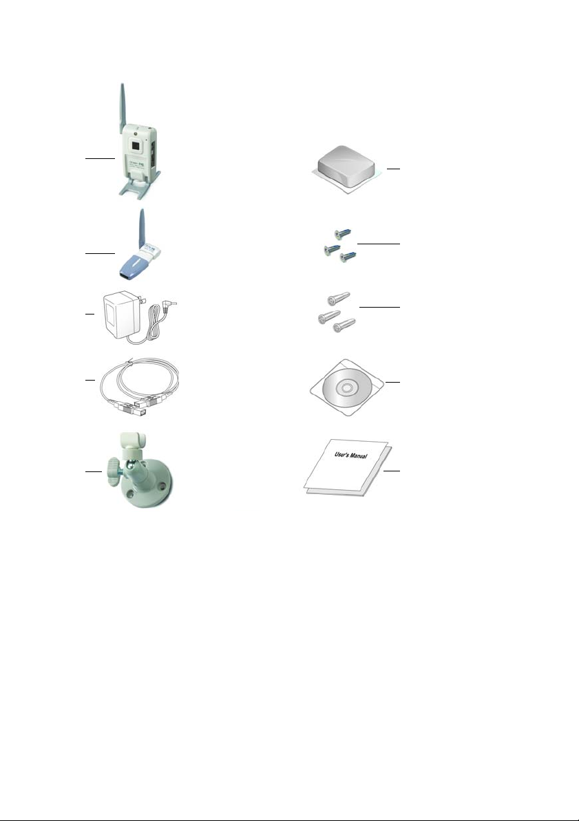
Out of the Box 0
A
B
C
D
E
Figure 1. Out of the Box
F
G
H
J
K
1 X Wireless digital camera (A)
1 X Wireless USB receiver (B)
1 X Mini USB AC adapters (C)
1 X USB cable extender (D)
1 X Wall mount (E)
1 X Tack adhesive putty (F)
3 X screws (G)
3 X screw anchor (H)
1 X Installation disk (J)
1 X User manual (K)
2
Page 9
Product Views 0
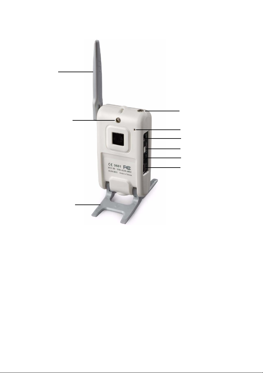
Antenna
LED Sensor
LED Support
Light
Microphone
Power Switch
Pairing Button
LED
DC IN
Camera Stand
Figure 2. Camera TX Front View
3
Page 10
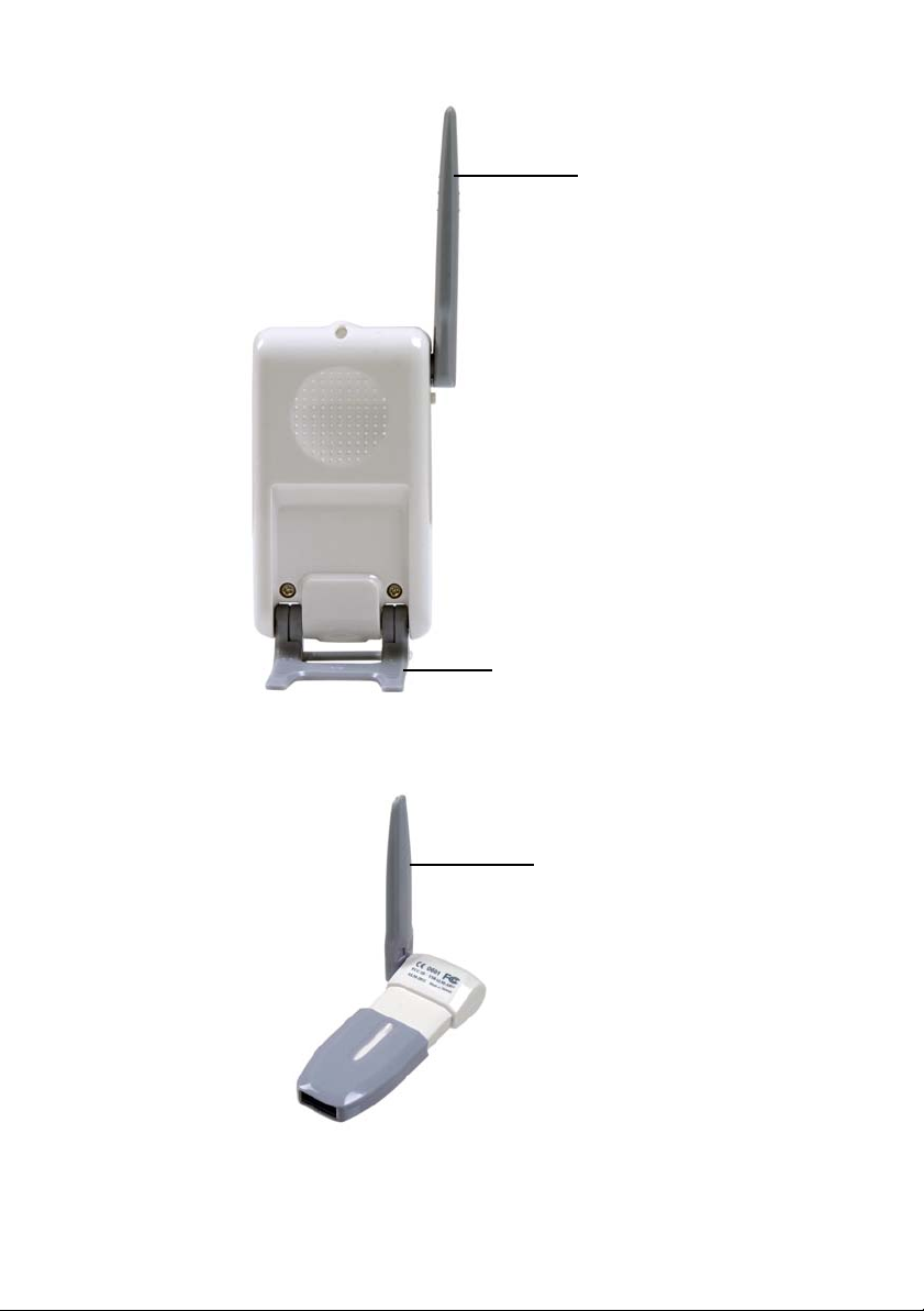
Camera Stand
Figure 3. Camera TX Rear View
Antenna
Antenna
Figure 4. USB RX
4
Page 11
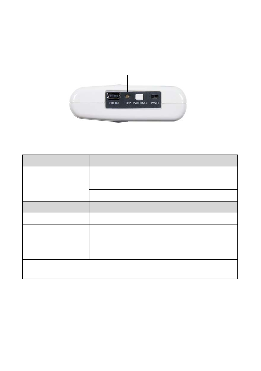
LED Definitions 0
LED
Figure 5. Camera TX LED Location
Camera TX
LED/Battery Power Definition
Green light On Power On
Green light flashing Fast: During pairing process
Slow: Paired
LED/AC Adapter Definition
Red light On When camera is plugged into the USB AC adapter
Green light On Power On
Green/ Red light
Alternating Flash
NOTE: Red light on or green/red light alternating flashing all means battery
is charging.
NOTE: When camera turned on and paired, do not press p a iring switch. On ce
pressed the device will lose connection and will need to be paired
again.
Fast: During pairing process
Slow: Paired
5
Page 12
Night view support LED on Camera TX 0
When the Camera TX and USB RX are paired and functioning, the
sensor on the Camera TX (top-right side) will automatically turn on the
LED support light (above the camera lens) when it detects the
environment is lacking light. The light will turn off automatically when
the light strong enough.
NOTE: When the Camera TX is unplugged, the LED support light will be
at half brightness.
NOTE: It is recommended to plug the Camera TX in when using it for
extended periods of time.
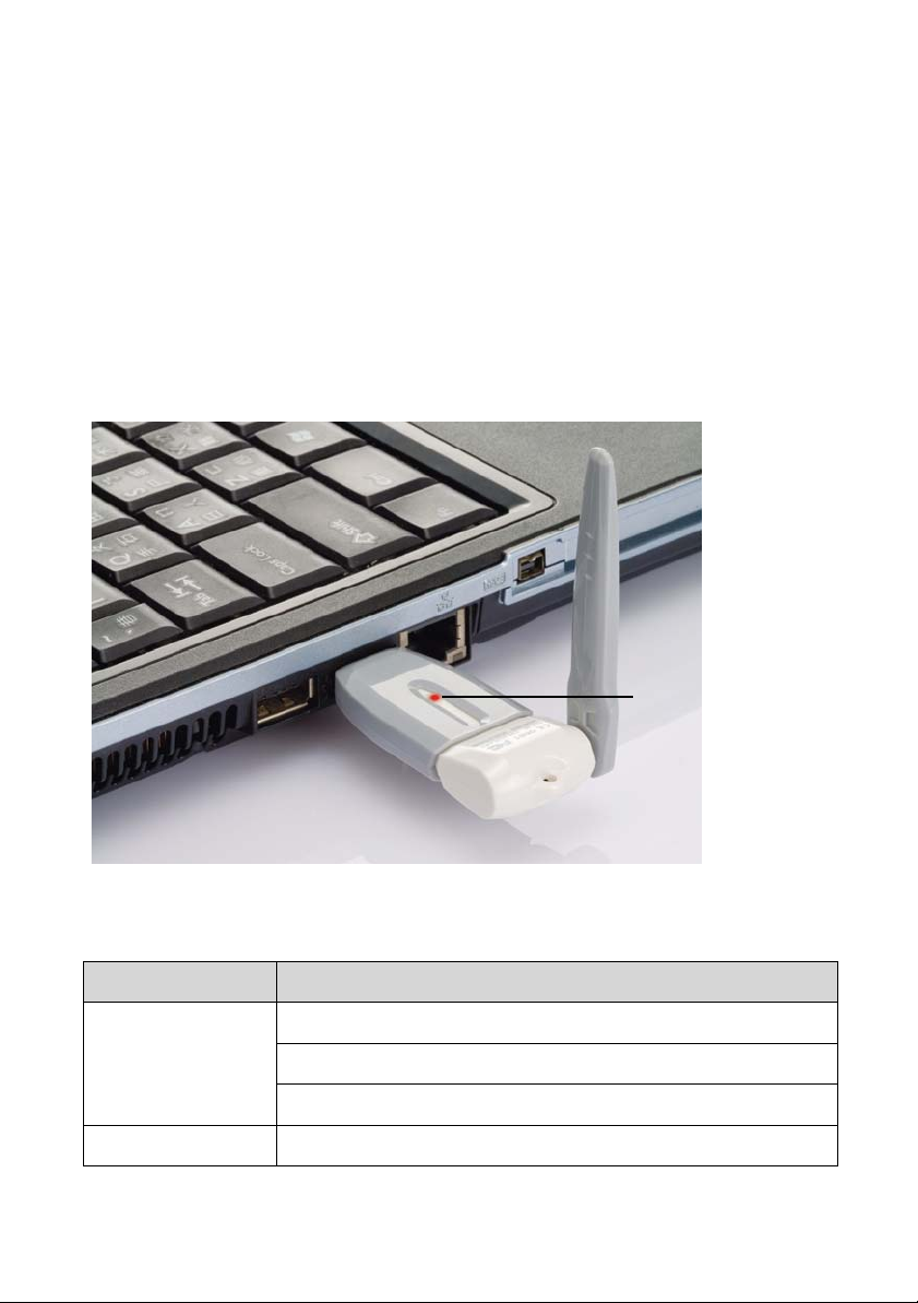
LED
Figure 6. USB RX LED Location
USB RX dongle
LED Definition
Red light on First time use or not paired with Camera TX
No connection
Camera off or out of power
Red light flashing Paired and functioning properly
6
Page 13

Chapter 2: Hardware Installation
General Information
This chapter contains step-by-step instructions for installing the USB WiGuard
hardware.
General Requirements 0
Mini network camera
USB powered wireless receiver
USB cable extender (optional)
Wall mount with screws and anchors (optional)
Phillips screwdriver (optional)
Tack adhesive putty (optional)
Important Installation Information 0
1. This product is operated under a 2.4GHz op en channel. To prevent
interference, do not install the unit close to household electronic products
such as a microwave, a 2.4GHz wireless phone, or a wireless AP.
2. Avoidi ng metal furniture or electronic equipment can extend the
transmission range and improve the signal reception. This product use s a
digital micro-wave band. For the best transmission, place the unit on a
higher position (using USB extension cord).
3. Please do not use the unit under high temperature an d humidity. This
product is not waterproof.
4. The lens of the camera sh ould always be clean. Do not touch the lens with
hands or wipe with an unknown solvent. Only wipe the lens gently with a
clean, soft cloth.
0
5. Do not try to dissemble or change the unit. Please follow troubleshooting
instructions to resolve problems.
6. The tack adhesive putty included in the package should be used for
temporary mounting. Please use the mounting kit for permanent use.
7. The attached antenna is a coaxial transmission antenna. Please do not
twist or wrench it.
8. Please keep away from infants or children under 10 years old.
7
Page 14
Determine a Location 0
Elevate the cameras and receiver to improve signal strength
Make sure the cameras and receiver are not blocked by any objects that
could weaken the signal or block the view of the camera
To prevent interference, avoid placing the camera or receiver close to
household electronic products such as a microwave, a 2.4GHz wireless
phone, or a wireless AP.
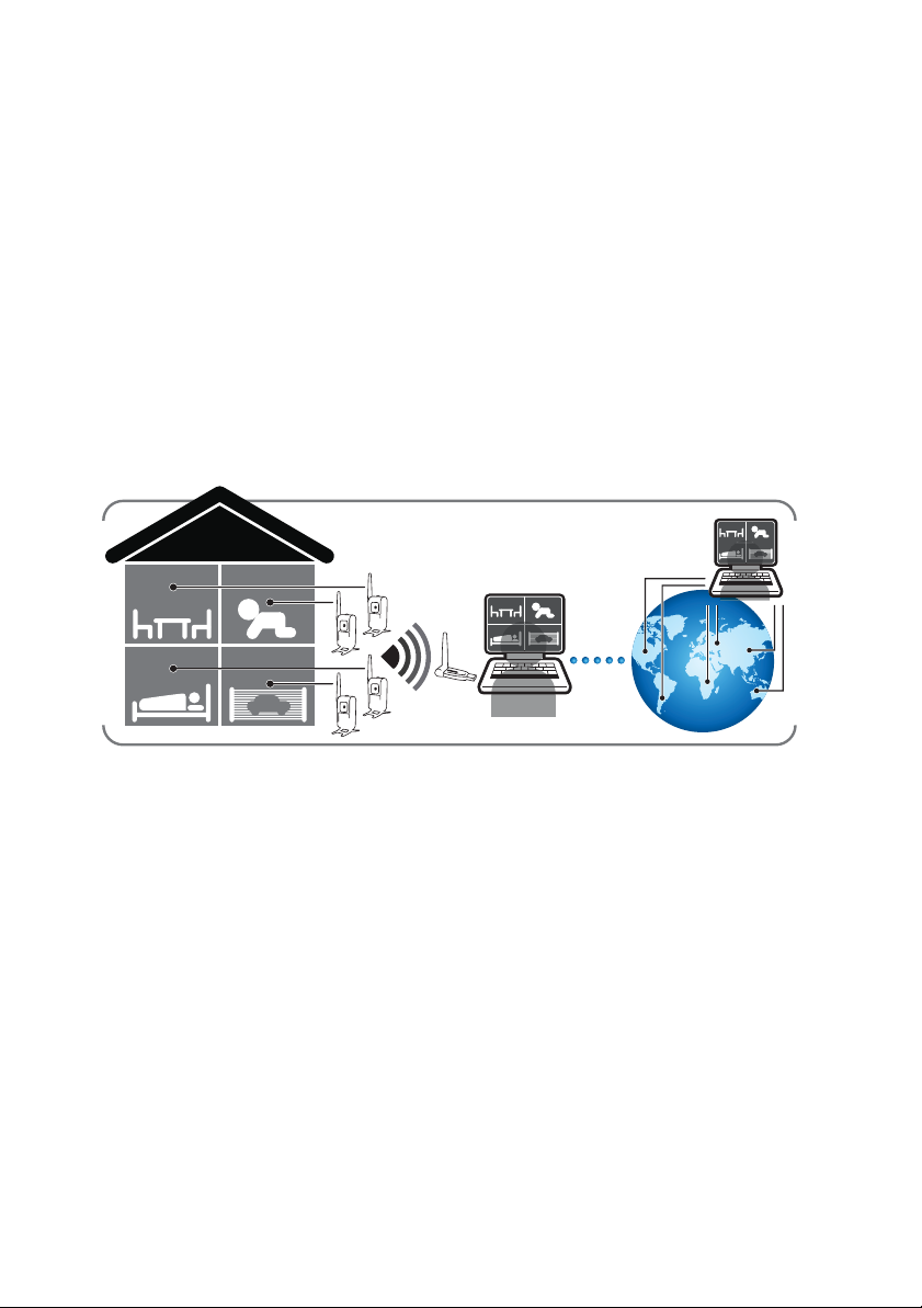
Line of Sight Considerations 0
When considering locations for the camera and receiver, the more direct the
line of sight is from the camera to the receiver, the stronger the signal will be.
Camera 1 Camera 2
Camera 3 Camera 4
Figure 7. Line of Sight
PC
300 m
Internet
PC
8
Page 15
Camera TX Installation 0
Mounting Modes 0
The camera can be mounted various ways. Users can mount the camera to
a desktop, a wall, or hang it from an object.
Desktop Mounting 0
When mounting the camera to a desktop, use the attached camera
stands.
NOTE: It is recommended to lower one stand before lowering the other.
Figure 8. Desktop Mount
9
Page 16
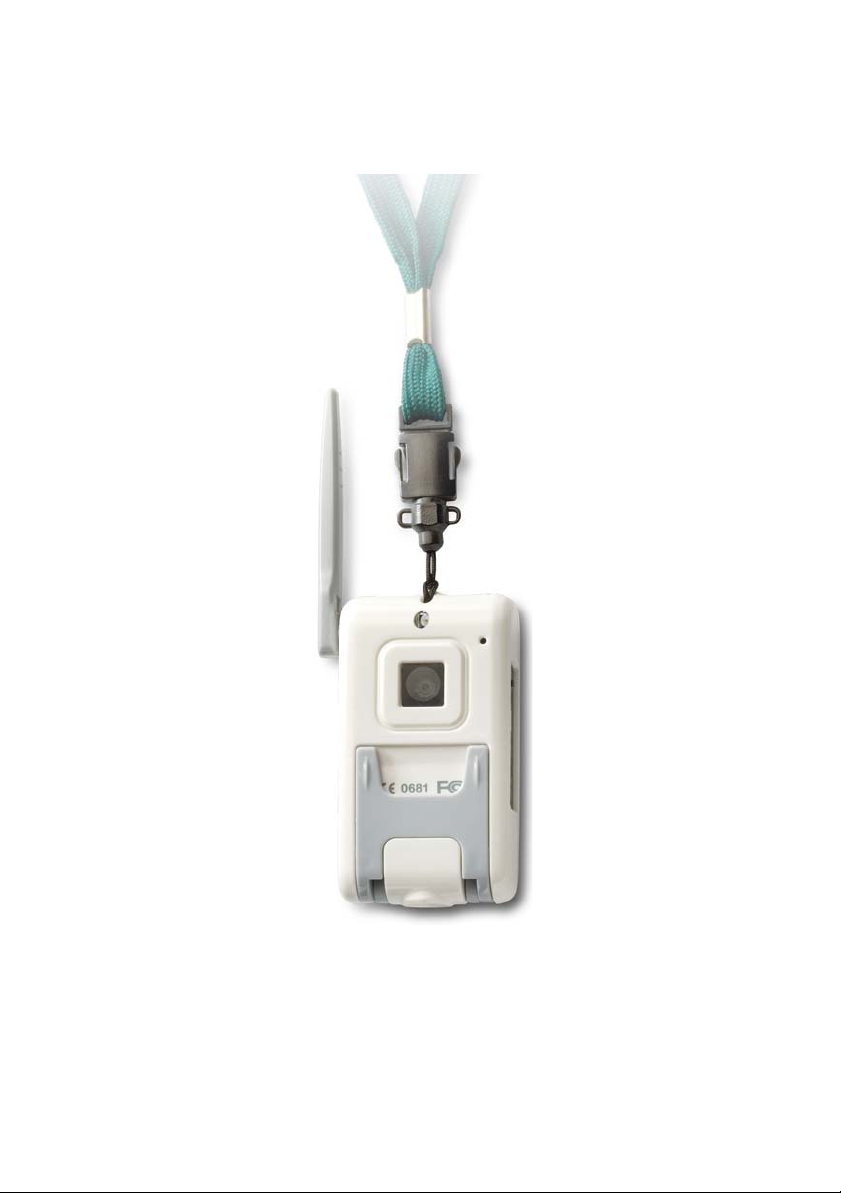
Hanging 0
When hanging the camera, use the loop hole on the top on the camera.
10
Figure 9. Hanging
Page 17
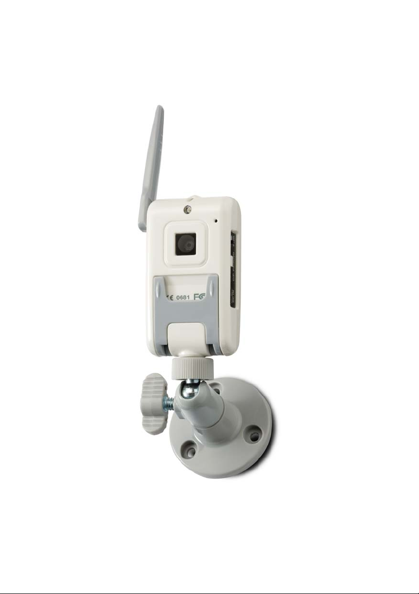
Wall Mounting 1 0
When using the wall mount, use the included screw anchors to
strengthen the connection to the wall.
Figure 10. Wall Mount 1
11
Page 18
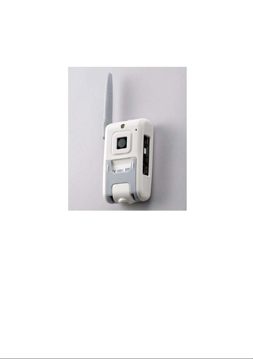
Wall Mounting 2 0
When using the tack adhesive putty, work the putty with your fingers to
make it more sticky. Also, clean the surface of where you want to place
the camera.
Figure 11. Wall Mount 2
Charging the Battery 0
Use the mini USB adapter to charge the LI-MH battery in the camera. When
the battery is charging, the LED on the camera will be red. The LED will turn
green when the battery is fully charged.
NOTE: Charge the battery for three hours before using it.
12
Page 19
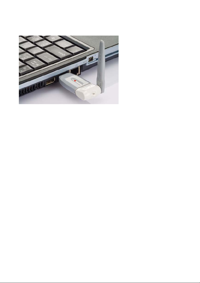
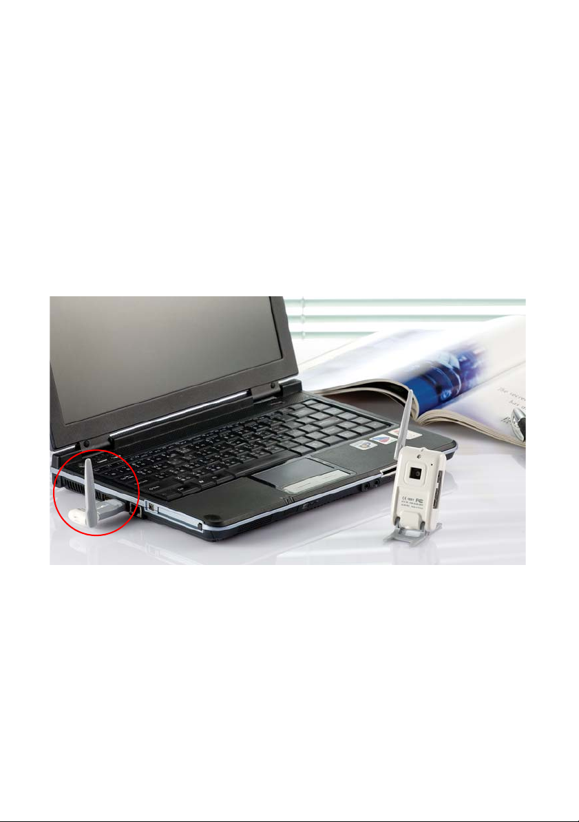
USB RX Installation 0
Figure 12. Connect to USB port
1. Install the software first.
2. Install the USB RX receiver into the USB port of your computer.
3. Please click the .exe file on the Windows desktop to start the system.
NOTE: It is recommended to use the USB cable extender and make sure
there are no objects blocking the line of sight of the dongle.
13
Page 20

14
Page 21
Chapter 3: Installing the Software
Introduction
This chapter describes the installation procedure for the USB WiGuard Software.
System Requirements 0
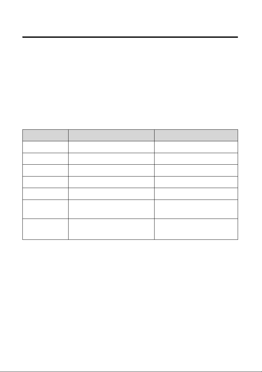
System Requirements
Device Minimum Recommended
CPU
RAM 512 MB or above 1 GB or above
Network Ethernet port Ethernet port
Resolution 800 x 600 (24 bits) 1024 x 768 (24 bits)
IP Cam 1 or more 1 or more
Operating
Software
Windows
Media Player
Pentium 4, 2.0 GHz or above Pentium 4, 3.0 GHz or above
Windows 2000
Windows Media Player 9
®
®
Windows XP® or Vista
®
Windows Media Player 9®
or above
®
0
15
Page 22
Installation 0
1. Power on your computer and make sur e no other application s are runnin g.
2. Insert the installation disc into the computer.
3.
Using Windows Explorer®, browse to your disc drive to locate the
setup_WUSB_WHQL_Driver_A1009_A1007_NVR_Big5_100917.exe
and double click on the file.
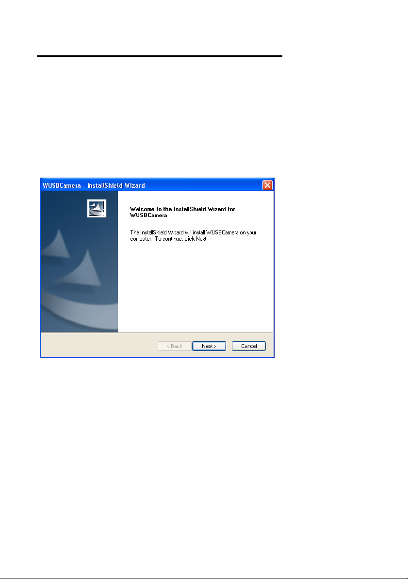
4. The install wizard for the WUSBCamera will launch. Click Next to continue
the installation.
file
Figure 13. Installation wizard
16
Page 23
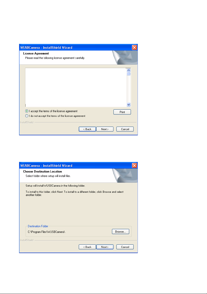
5. Read the following license agreement and select accept if you agree to the
terms and click Next. If you do not agree to the terms, click Cancel to end
the installation wizard.
Figure 14. License agreement
6.
Select the destination folder of where the files will be installed and click
Next
.
Figure 15. Destination folder
17
Page 24
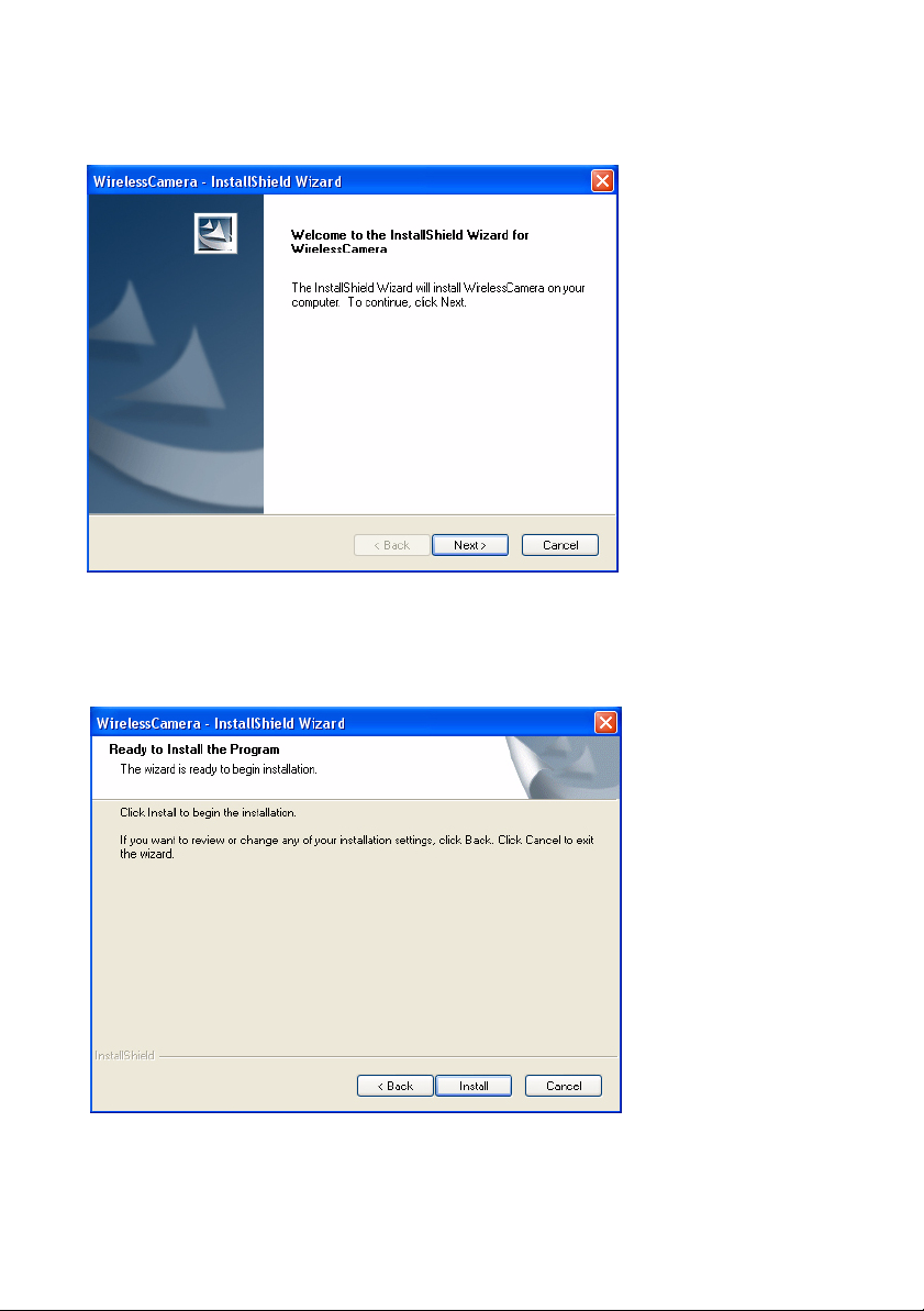
7. The install wizard for the WirelessCamera will launch. Click Next to
continue the installation.
Figure 16. Installation wizard
8. Click Install to begin the installation.
Figure 17. Launch installation
18
Page 25
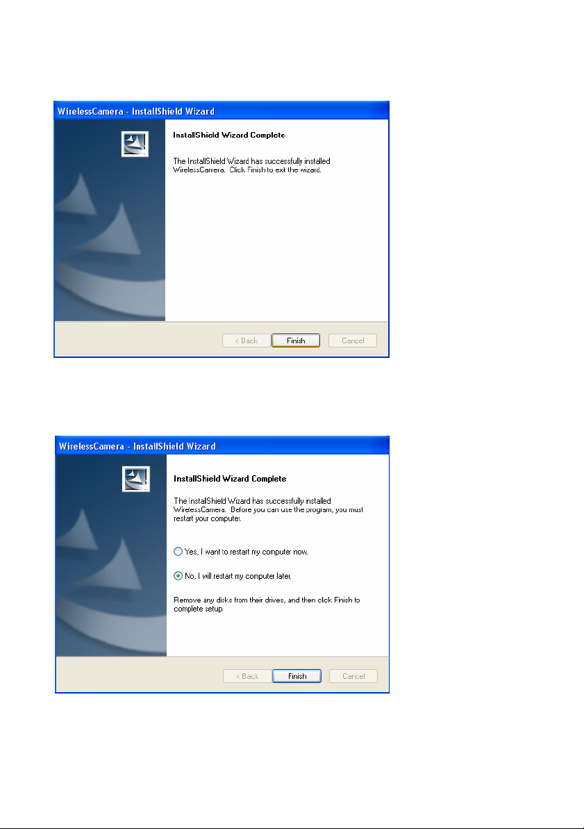
9. The wizard will confirm if the software has installed successfully. If it has
installed correctly, click Finish. If the software did not install completely ,
click Cancel and reinstall the software beginning at step 3.
Figure 18. Finish installation
10. Select option No, I will restart my computer later and click Finish.
Figure 19. Restart
NOTE: The computer does not need to be res tarted to run th e ap plication.
19
Page 26

20
Page 27
Chapter 4: Functions of the WiGuard
Introduction
This chapter describes functions of the USB WiGuard software.
Menu Elements 0
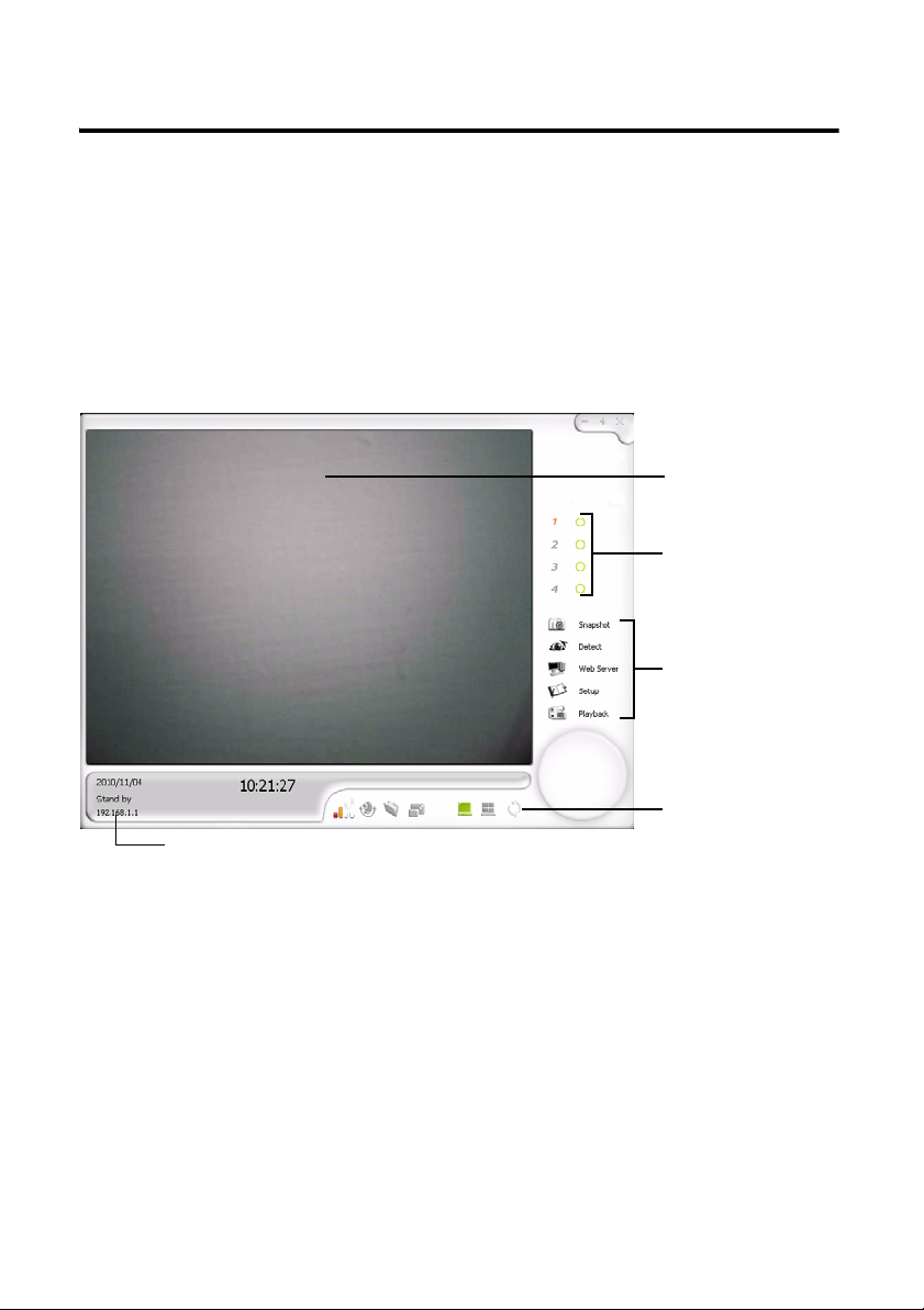
1: Monitoring
Screen
2: Channel
Status
3: Option
Menu
4: Camera and
Screen
5: Channel Information
Control
0
Figure 20. USB WiGuard Interface
21
Page 28
Monitoring Screen 0
This area will show the camera’s view . It can be customized to show one
screen or multiple screens.
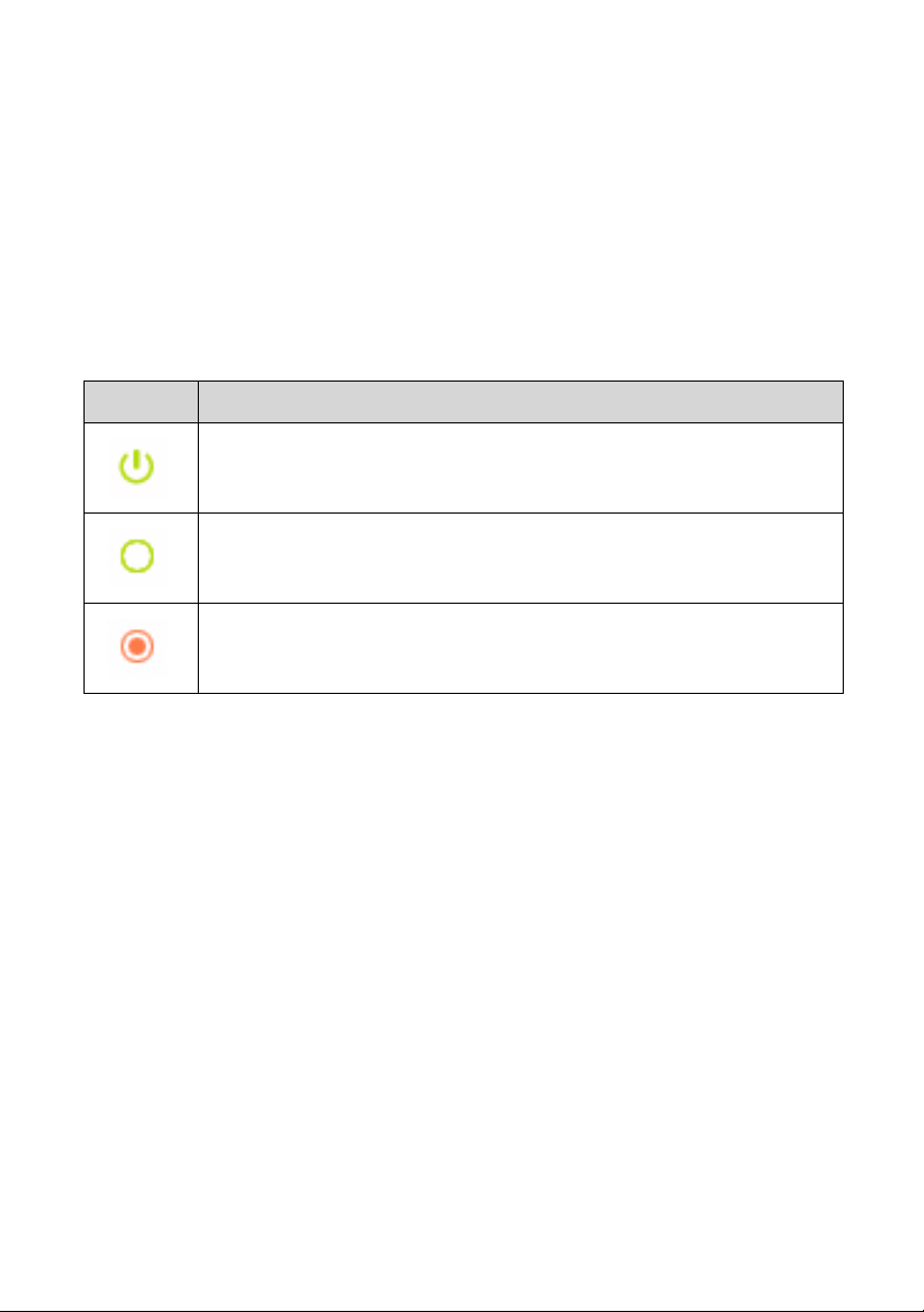
Channel Status 0
This area will show the status of individual cameras.
Channel Status
Icon Description
Indicates the camera is monitoring.
Indicates the camera is in standby mode.
Indicates the camera is recording.
22
Page 29
Option Menu 0
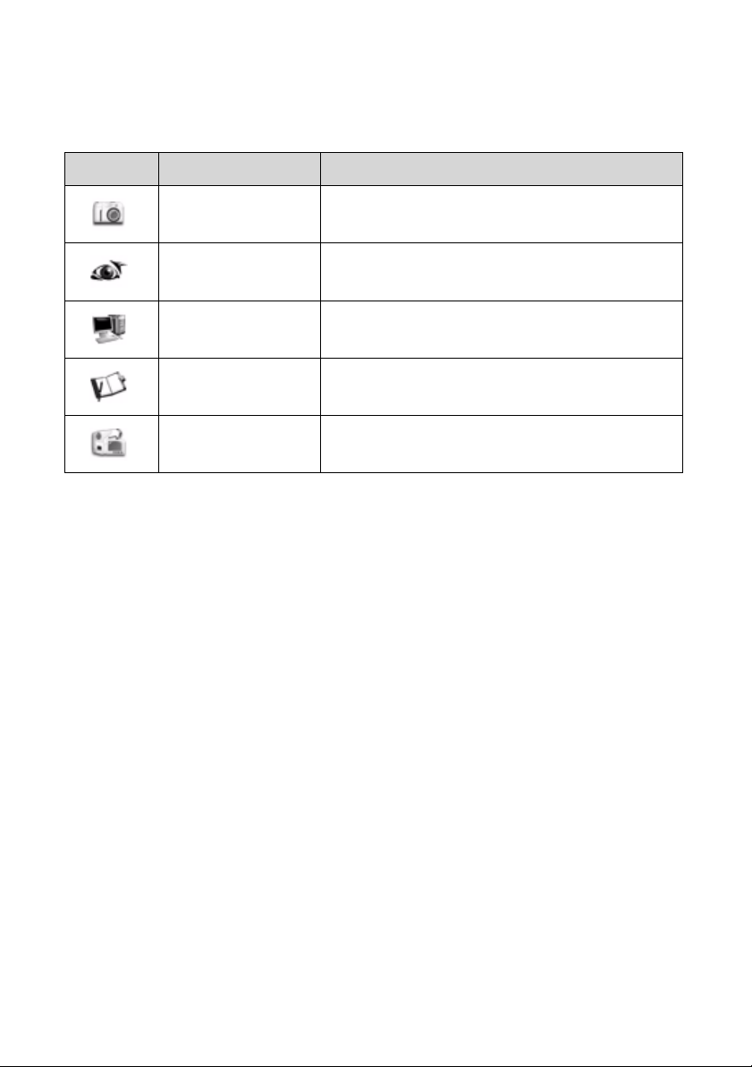
This area allows users to perform actions shown in Table .
Option Menu
Icon Item Description
Snapshot Takes a snapshot of the monitoring screen.
Detect Turns the motion detection on/off.
Web Server Turns the web server option on/off.
Setup Launches the System and Setting setup
menus.
Playback Launches the playback interface.
Snapshot 0
The snapshot function allows you to take an instant image of what is
showing on the screen. When the snapshot button is clicked, it stores a
.jpg file in the snapshot folder.
Detect 0
The detect function turns the motion detection op tion, ON or OFF. When
the image changes, the software will capture a .wmv file and save it in
the video folder.
Web Server 0
The web server function turns the web server option, ON or OFF. When
the web server option is turned on, users can log in through the internet
to view the cameras live.
NOTE: When the web server option is on, the setup option will be
locked.
Setup 0
The Setup option lets you configure the Digital Wireless NVR Camera
System to your own specifications. See “System Setup” on page 30.
23
Page 30
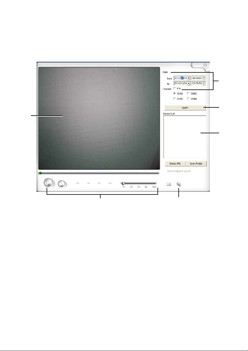
Playback 0
This section allows you to search for and playback recorded videos.
1
2
3
4
5
Figure 21. Playback
1. Main Display Screen: This area will display the video output of the
recording
2. Date and Channel selection: This filters out when and which
channels the videos within that search criteria.
3. Once the search criteria has been determined, click the Query
button to perform a search.
4. Record list: This area will show a list of videos within the search
criteria. Users have the option to delete it or open the file directory
of your videos.
24
6
Page 31

5. Playback controls: (From left to right)
Play
Stop
Previous track
Rewind
Fast forward
Next track
Playback speed (1x, 2x, 4x, 8x, 16x)
6. Capture options: Use the camera to capture a picture on the main
display screen and use the folder to access the captured picture(s)
Camera/Screen Control 0
This area allows users to perform actions shown in the Camera and Screen
Control Table .
Camera and Screen Control
Icon Item Description
Signal Strength Displays the signal strength of the wireless
camera.
Cruise Pairs cameras to camera numbers.
Pictures Opens the snapshot folder.
Screen size Adjusts the screen size on the monitoring
screen.
Single View Displays one channel on the monitoring
screen.
Tile View Displays multiple channels on the
monitoring screen.
25
Page 32
Channel Information 0
Shows the current channel information.
Channel Information
Item Description
Date Shows the current date
Camera Status Shows the status of the camera
IP Address Shows the IP address
26
Page 33
Chapter 5: Operation
USB RX Installation
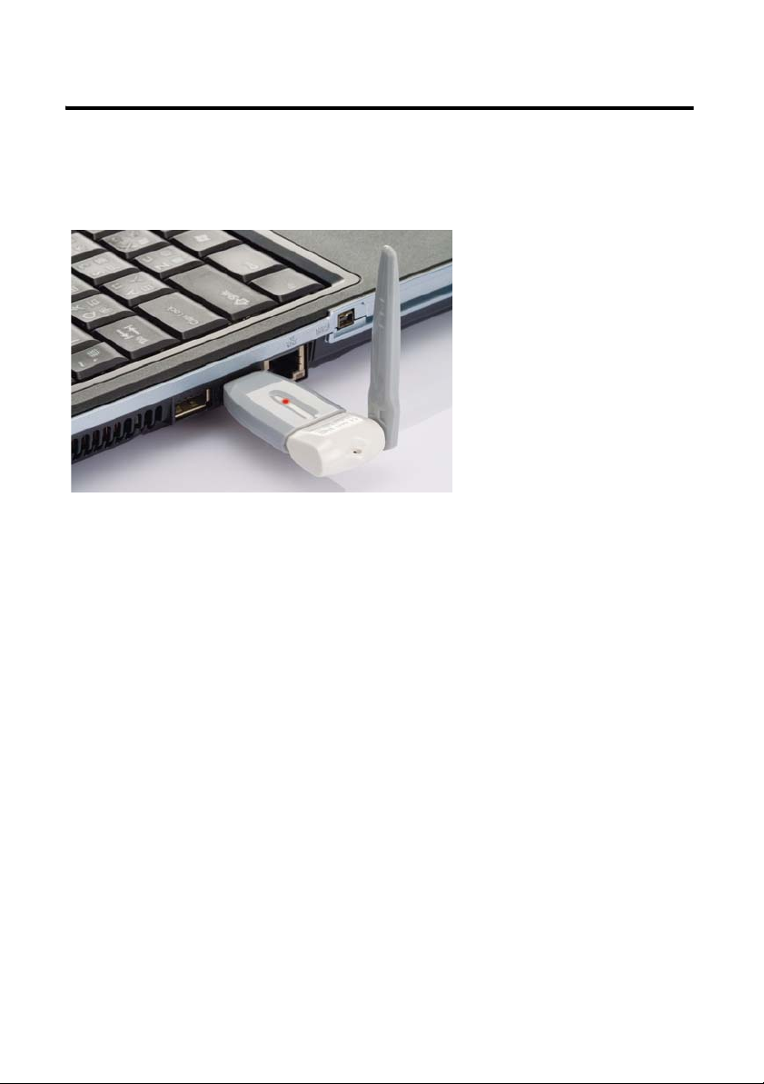
Figure 22. Connect to USB port
1. Install the software first.
2. Install the USB RX receiver into the USB port of your computer.
3. Please click the .exe file on the Windows desktop to start the system.
NOTE: It is recommended to use the USB cable extender and make sure
there are no objects blocking the line of sight of the dongle.
0
Pairing a USB WiGuard 0
1. Launch the USB WiGuard Software. Start Menu´All
Programs´Wireless Camera´WUSB Camera.
2. Click on the Cruise button in the Camera and Screen Control menu to
launch the Match Setting window.
27
Page 34
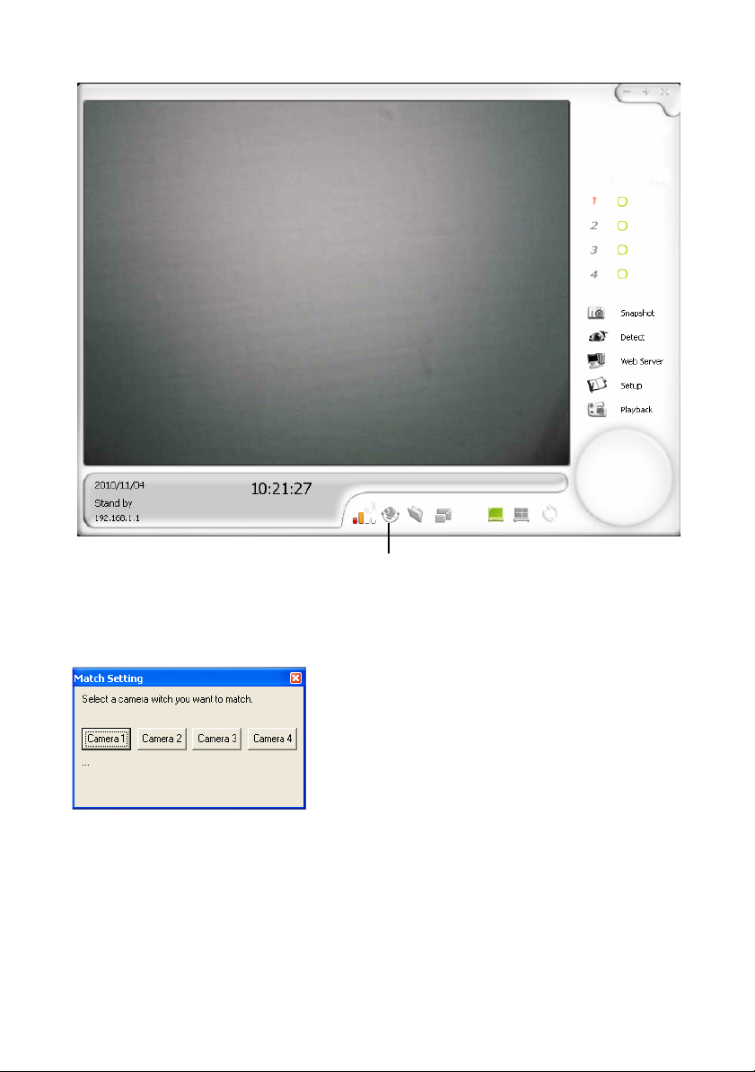
Figure 23. Cruise Button
3. Select the camera number you want to pair with a camera.
Figure 24. Match Setting
4. Within 10 seconds, turn on the camera TX and press the p airin g button on
the camera. The LED will flash quickly when pairing and slowly when
paired. The Match Setting window will also display the pairing status.
Repeat steps 3 and 4 for each camera.
NOTE: Place the camera and receiver close to each other when pairing
them.
28
Cruise
Page 35
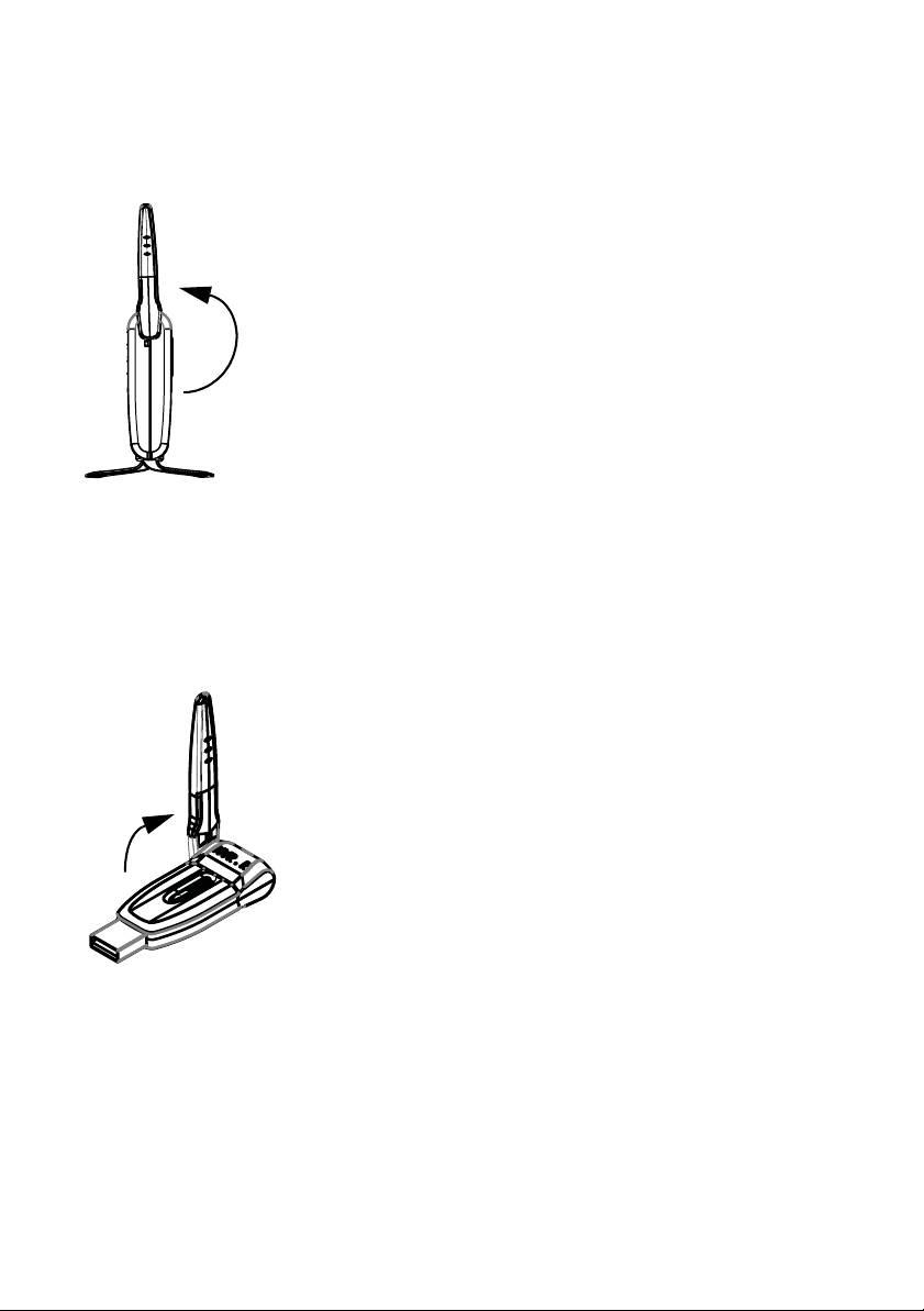
Adjusting the Antenna on Camera TX
1. Lift the antenna on the wireless camera as shown in Figure 25.
Figure 25. Camera Antenna
0
Adjusting the Antenna on USB RX
1. Lift the antenna on the USB dongle as shown in Figure 26.
Figure 26. USB RX Antenna
0
29
Page 36
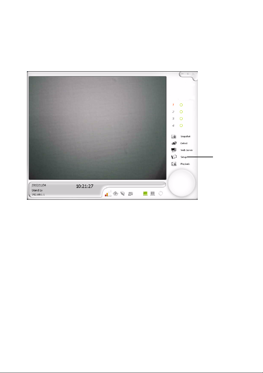
System Setup
The Setup option allows you to Set up the Digital Wireless NVR Camera
System. In the options menu, click Setup to open the System Settings
window. (Figure 27)
Setup
Figure 27. Setup Button
0
30
Page 37
1
5
2
6
3
4
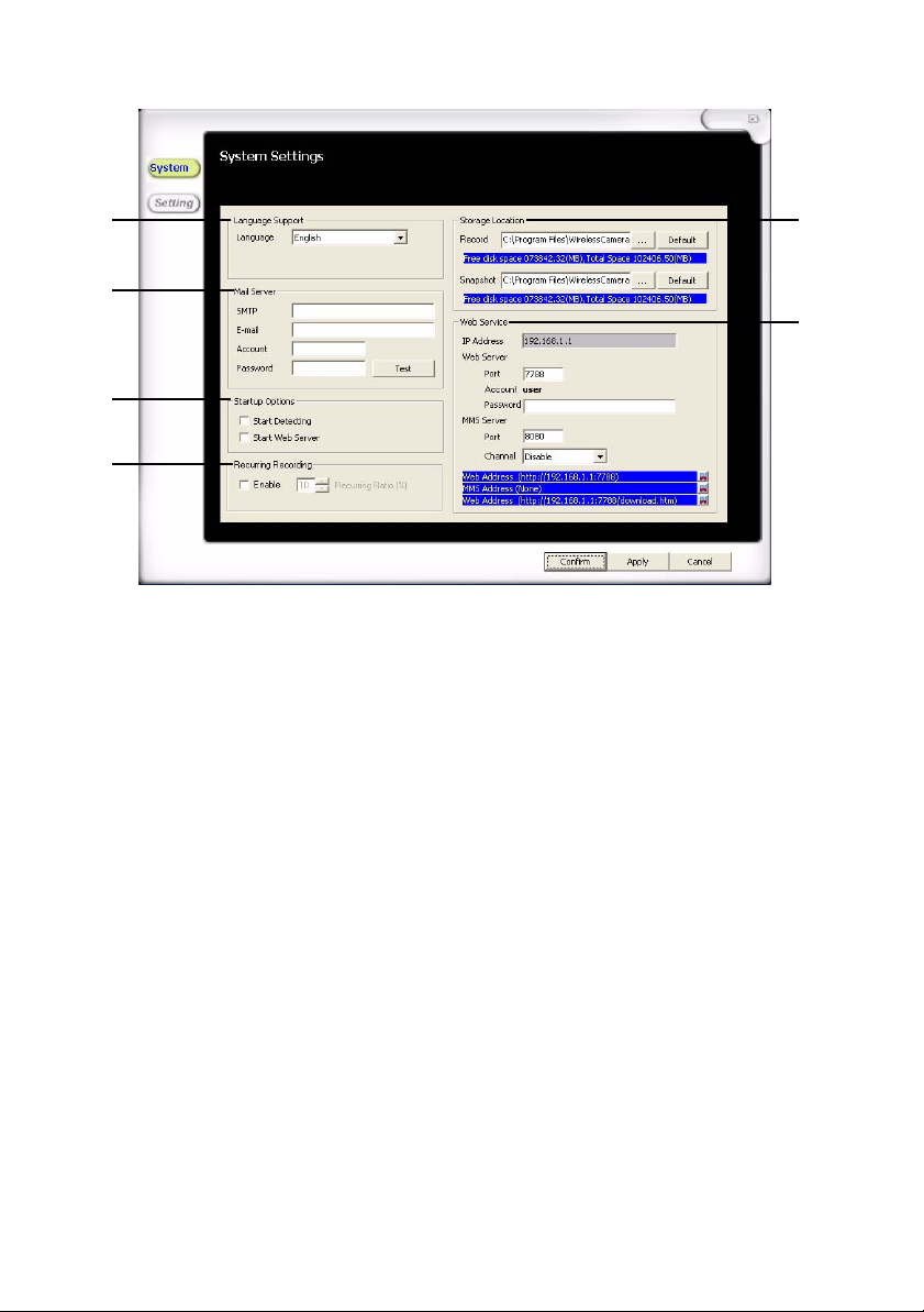
Figure 28. System Setup
1. Language Support: Sets the language used in the interface
2. Mail Server: Lets users change mail server settings for e-mail notification
when motion detection occurs
3. Startup Option s: Allows user to pre-determine start up options including:
Start Detecting: Starts the viewer in detection mode
Start Web Server: Starts the viewer web server
4.
Recurring Recording:
Records over older files to save space for the hard disk
5. Storage Location: Locations of where the files are being saved for
recorded videos and captured images
6. Web Service: Settings for the web server
IP Address: The IP address of the web service for the viewer
Web Server Port: The port for the web server is 7788
Web Server Account: Default is “user”
Web Server Password: Password for the web service
MMS Server Port: The port for the MMS server is 8080
MMS Server Channel: The channel for the MMS service
31
Page 38
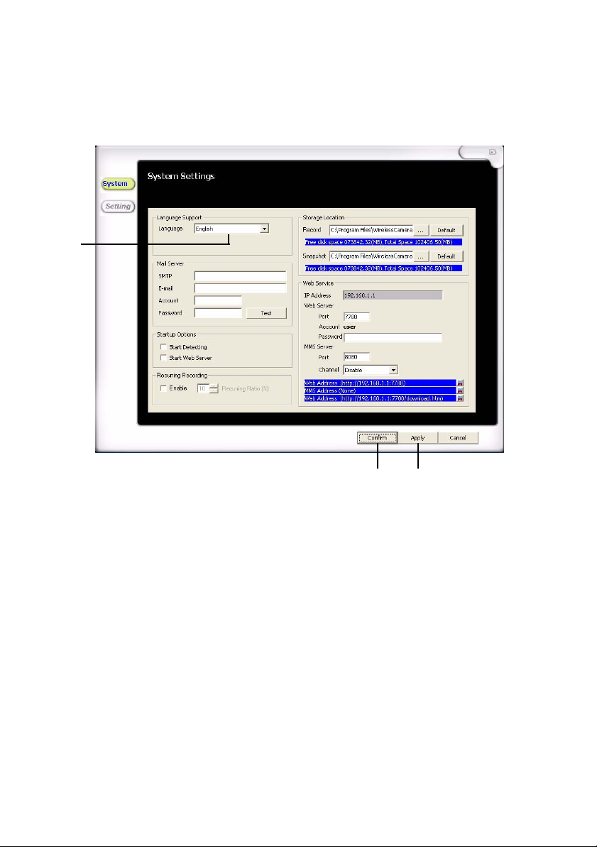
Setting Up the Language Support 0
1. In the options menu, click Setup to open the System Settings
window. (Refer to Figure 29)
2
Figure 29. Language Support
2. Select the applicable language from the drop down menu.
3. Click Apply to approve the setting.
4. Click Confirm to exit the System Settings window.
32
34
Page 39
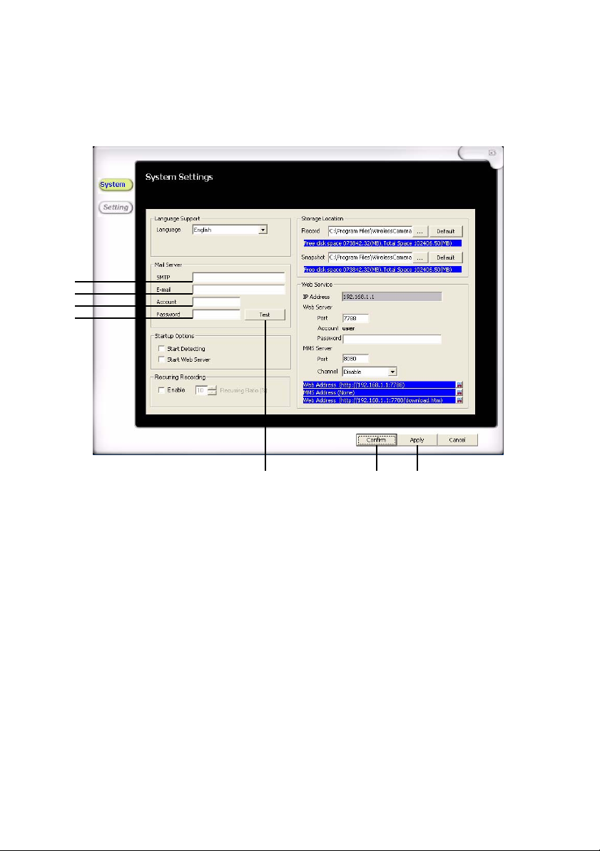
Setting Up the Mail Server 0
1. In the options menu, click Setup to open the System Settings
window. (Refer to Figure 30)
2
3
4
5
6
Figure 30. Mail Server
2. Enter the SMTP information in the SMTP field.
3. Enter the email address that will receive the notifications in the
email field.
4. Enter the account name for the email address you want to receive
the notifications in the account field.
5. Enter the password for the email address you want to receive the
notifications in the password field.
6. Click Test to make sure that the settings are working correctly . If the
test was successful, a window will pop up confirming the test and an
email will be sent to the email address.
7. Click Apply to approve the setting.
8. Click Confirm to exit the System Settings window.
78
33
Page 40
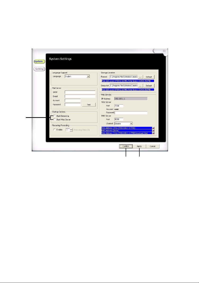
Setting Up the Startup Options 0
1. In the options menu, click Setup to open the System Settings
window. (Refer to Figure 31)
2
34
Figure 31. Startup Options
2. Put a check mark in the startup options you want to automatically
run when the software is started.
3. Click Apply to approve the setting.
4. Click Confirm to exit the System Settings window.
34
Page 41
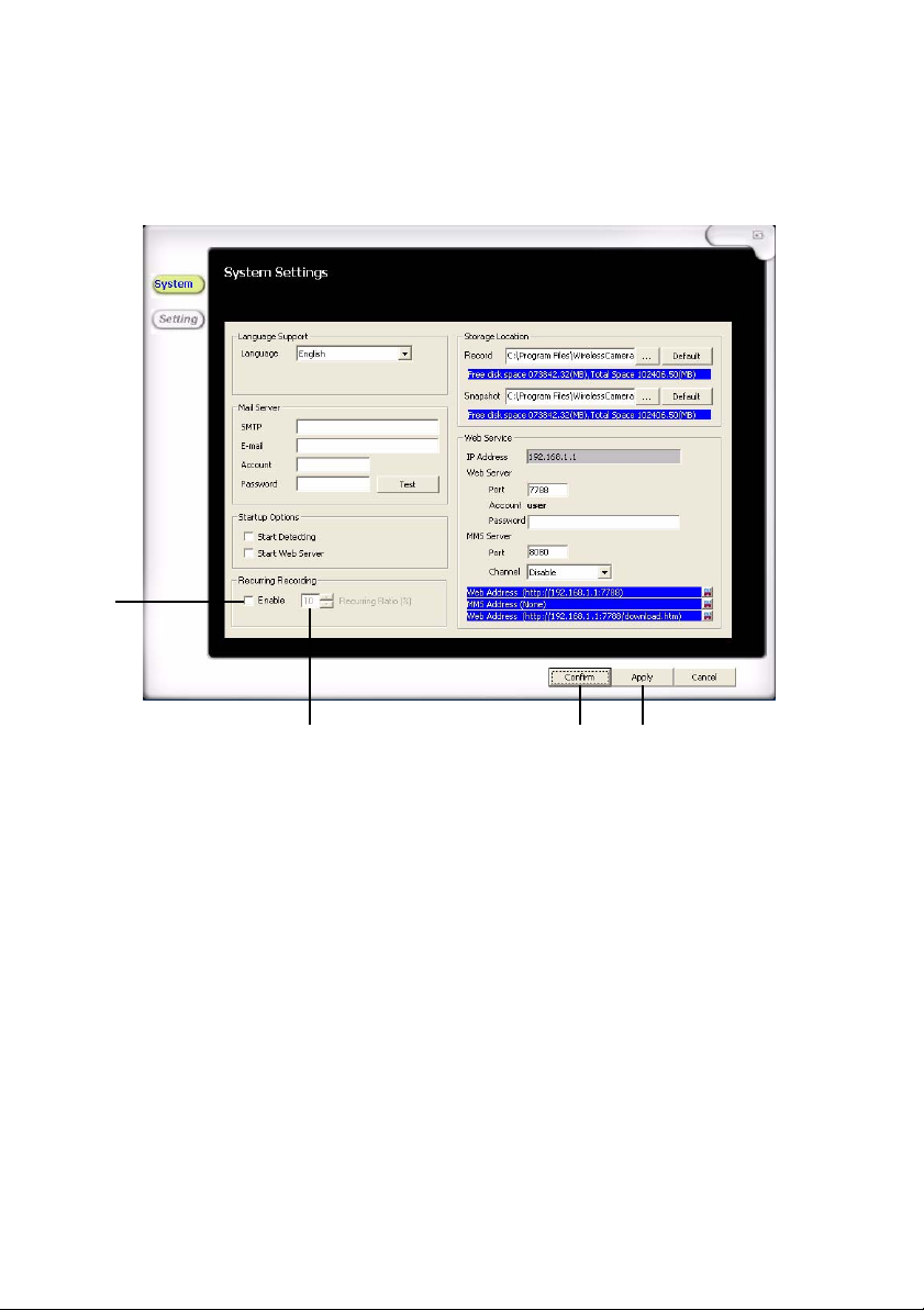
Setting Up the Recurring Recording 0
1. In the options menu, click Setup to open the System Settings
window. (Refer to Figure 32)
2
453
Figure 32. Recurring Recording
2. Click Enable to turn Recurring Recording on.
3. Enter in the percentage of free disc space you want to make
available for the video recording.
4. Click Apply to approve the setting.
5. Click Confirm to exit the System Settings window.
35
Page 42
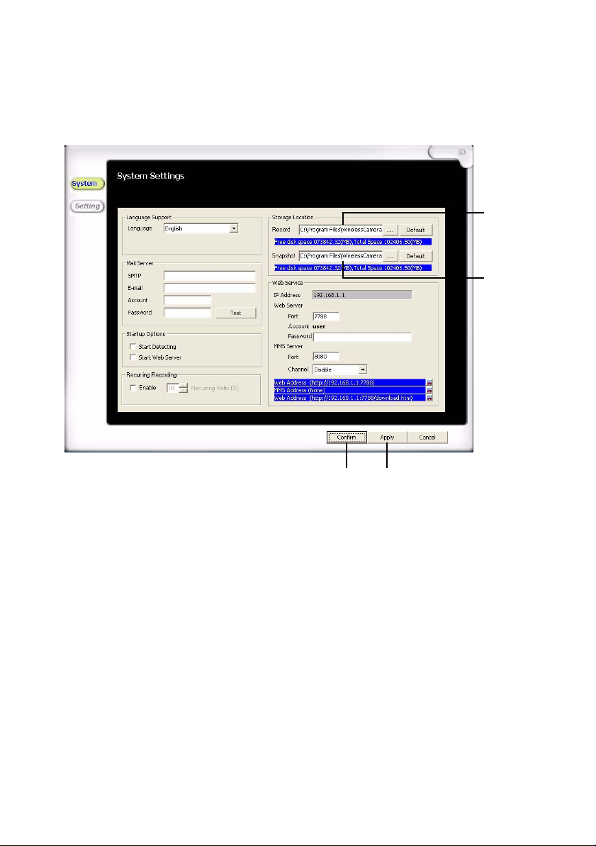
Setting Up the Storage Location 0
1. In the options menu, click Setup to open the System Settings
window. (Refer to Figure 33)
2
3
45
Figure 33. Storage Location
2. In the Record field, enter the file path or click the ... button to select
the location the video files will be stored. Click Default to store the
files in the default location. To locate the default folder, refer to
Installation on page 16.
3. In the Snapshot field, enter the file path or click the ... button to
select the location the image files will be stored. Click Default to
store the files in the default location. To locate the default folder,
refer to Installation on page 16.
4. Click Apply to approve the setting.
5. Click Confirm to exit the System Settings window.
36
Page 43
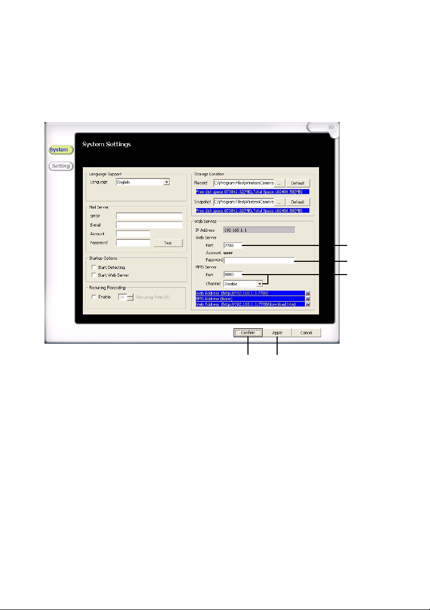
Setting Up the Web Server 0
1. In the options menu, click Setup to open the System Settings
window. (Refer to Figure 34)
NOTE: IP address is automatically aquired from network settings.
2
3
4
56
Figure 34. Web Service
2. Enter a Port number, such as 7788 into the Web Server Port field.
3. Enter the web server password in the password field. This is the
administrator password of the computer running the USB WiGuard
Software.
4. If you are using a mu ltimedia server, enter 8080 in the MMS Server
Port field and set the MMS Server Channel field to Enabled.
5. Click Apply to approve the setting.
6. Click Confirm to exit the System Settings window.
NOTE: Must have priveleges to change the network settings.
37
Page 44

Determining the IP Address 0
Windows XP®:
1. From the Start menu, right-click My Network Places, and
then click Properties.
2. To view the IP address of a wired connection, double-click
Local Area Connection.
3. To view the IP address of a wireless adapter, double-click
Wireless Network Connection.
4. Click the Support tab, and then click Details. The window
that appears will display the IP address.
Windows Vista
1. From the Start menu, right-click Network, and then click
Properties.
2. To view the IP address of a wired connection, click View
Status to the right of Local Area Connection.
3. To view the IP address of a wireless adapter, click View
Status to the right of Wireless Network Connection.
4. Click Details. The address is next to IPv4 IP Address.
Windows 7
®
:
®
:
38
1. In the system tray, click the network connection icon and
select Open Network and Sharing Center.
2. To view the IP address of a wired connection, click Local Area
Connection.
3. To view the IP address of a wireless adapter, click Wireless
Network Connection (Network Name).
4. Click Details. The address is next to IPv4 IP Address.
Page 45
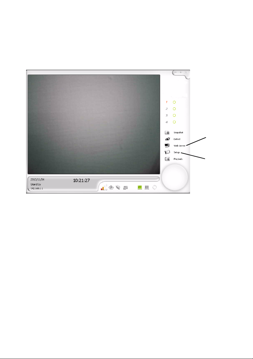
Using the Web Server 0
1. Once the web service has been set up, click the Web Server
button on the options menu to turn on the web server.
(Figure 35).
Web
Server
Setup
Figure 35. Web Server Button
39
Page 46

2. Open a browser.
3. Enter the IP address & port as shown in Figure 36 (Ex. http://
192.168.0.100:7888).
NOTE: To see the IP address, see Determining the IP Address on
page 38.
Figure 36. IP Address
4. The browser will display the camera view.
40
Page 47

MSN Webcam Setup 0
1. Make sure the Camera TX and USB RX have been paired.
2. Turn off NVR software.
3. Start MSN (Windows
4. Select Tools´Audio and Video Setup
5. Select the webcam and start the camera view
®
Live).
Skype Webcam Setup 0
1. Make sure the Camera TX and USB RX have been paired.
2. Turn off NVR software.
3. Start Skype™.
4. Select Tools´Options´Video Settings.
5. Select the webcam and start the camera view.
MMS Setup 0
1. Make sure the Camera TX and USB RX have been paired.
2. Start NVR software.
3. Click Setup and enable the MMS server.
4. The Port number is 8080.
5. Click Confirm.
6. Click the Web Server button on the options menu to turn on
the web server.
7. Open a web browser.
8. In the same location shown in Figure 36, type the MMS IP
Address and port. (Ex. mms://192.168.0.100:8080).
9. After entering IP address, a pop-up menu will appear.
10. Click Allow in the pop-up menu for Windows Media Player ®
to launch and stream video.
NOTE: Using MMS as webserver is high recommended.
41
Page 48
Camera Settings
Basic Settings 0
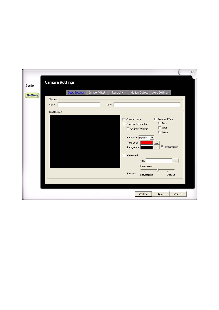
The Basic Settings tab allows you to show custom information on the
main screen, such as channel name, date and time, and watermarks.
0
Figure 37. Basic Settings
Channel: Contains a personal name and description of the
camera
Channel Name: Add a channel name
Note: Add a channel description
Text Display: Customize the information that can be displayed on
the channel’s screen
Channel Name: Shows the channel name
Channel Information: Shows the channel number and/or
channel name
Date and Time: Shows date, time, and/or week
42
Page 49
Font Size: Adjust the size of font on the screen
Text Color: Adjust the text color on the screen
Background: Adjust the text background color on the screen
Watermark: Add a watermark image to the scre en (.bmp or .jpg
files only)
Image Adjust 0
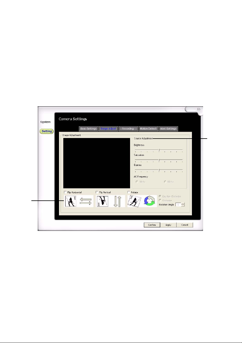
The Image Adjust tab allows you to adjust settings such as brightness,
saturation, gamma, and image rotation.
2
1
Figure 38. Image Adjust
1. The image properties can b e changed using the following options:
Flip Horizontal: Turns the image horizontally
Flip Vertical: Turns the image vertically
Rotate: Rotates the image based on rotation angle and direction
2. Adjust video parameters to change brightness, saturation, gamma,
and AC frequency.
43
Page 50
Record Setting 0
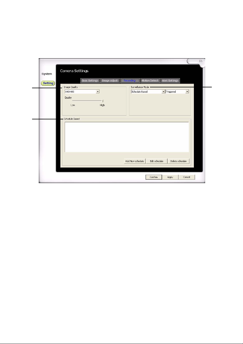
The Record Setting tab allows you to adjust image quality and configure
recording modes.
1
3
Figure 39. Record Setting
1. Image Quality: Changes the image resolution and quality
Resolution: Adjust the recording image size
Quality: Adjust the detail of the image
2. Surveillance Mode: Allows users to configure the recording mode
Schedule Based: Will go into detection mode based on a
configured scheduled. This mode can be set to record in either
full time or triggered mode.
Record (During Detection): Once in detection mode, it will record
in either full time or triggered mode
View Only (No Recording): Will only monitor in detection mode;
no recording will be done
NOTE: When set to Full-time, the Motion Detect and Alert Setting
tabs will be disabled.
2
3. Schedule Based: Allows users to preset a time to record.
44
Page 51
Add New Schedule
Edit Schedule
Delete Schedule
Add New Schedule 0
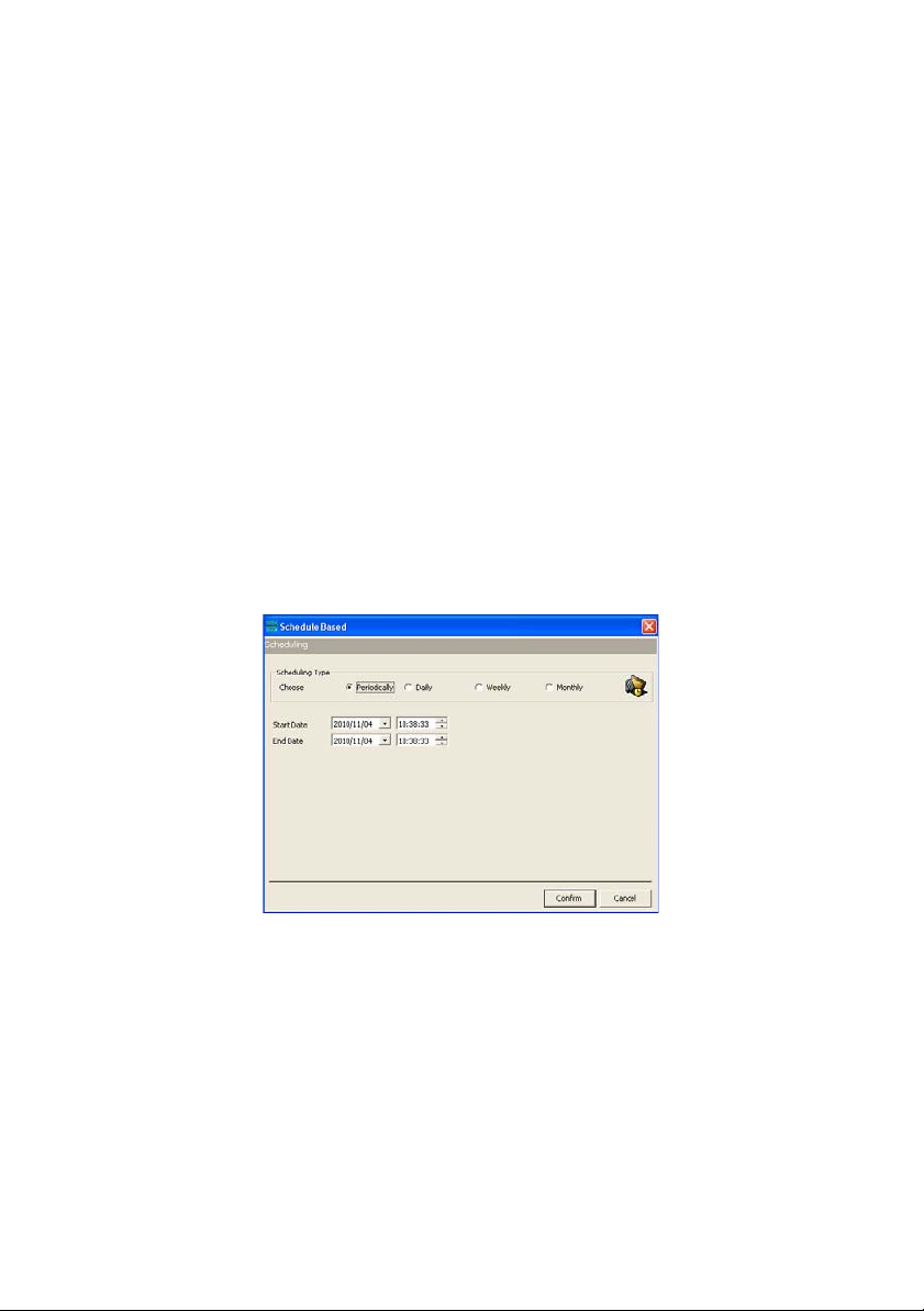
When Surveillance Mode is set to Schedule Based, you can set a
schedule to activate detection mode.
1. In the Recording tab, set the first drop down menu under
Surveillance Mode to Schedule Based.
2. Click the Add New schedule button.
3. Set the Scheduling Type:
Periodically
Set the start date and time
Set the end date and time
Figure 40. Periodically
Daily
Set the start time
Set the end time
Operative period: Set up the start and end dates of this
recording
45
Page 52
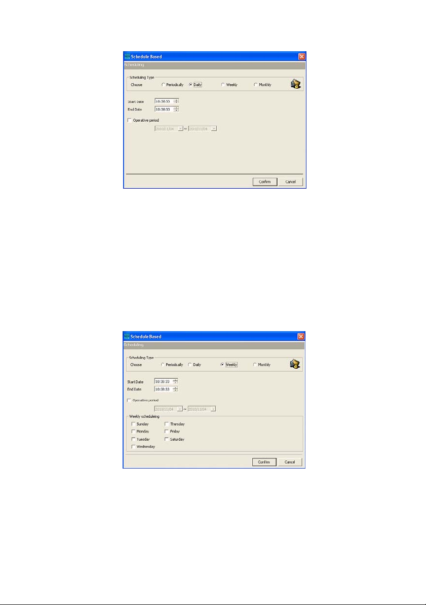
Figure 41. Daily
Weekly
Set the start time
Set the end time
Operative period: Set up the start and end dates of this
recording
Weekly scheduling: Select the days of the week the recordin g is
active
Figure 42. Weekly
46
Monthly
Set the start time
Set the end time
Operative period: Set up the start and end dates of this
recording
Page 53
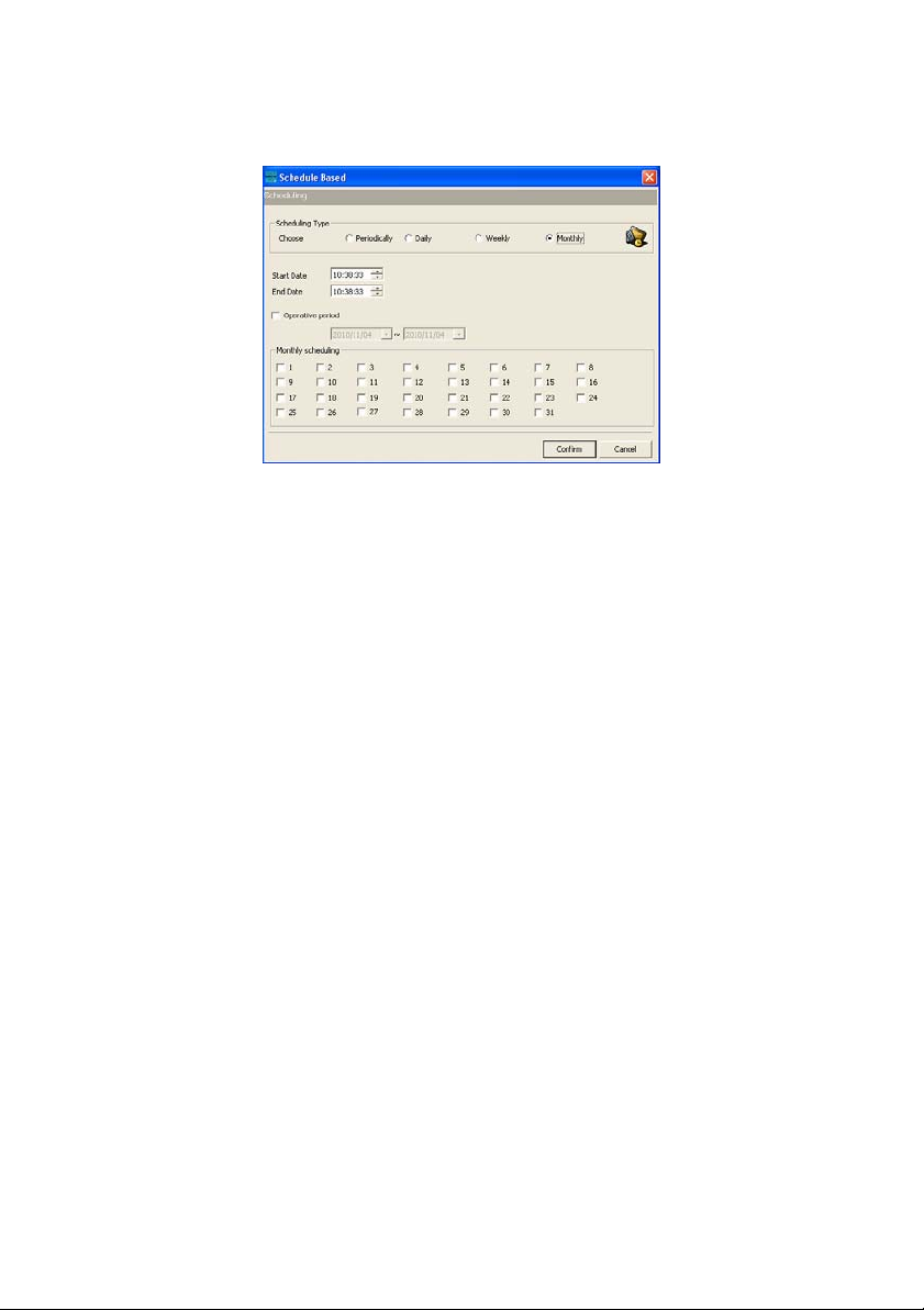
Monthly scheduling: Select the days within the month the
recording is active
Figure 43. Monthly
47
Page 54
Motion Detect 0
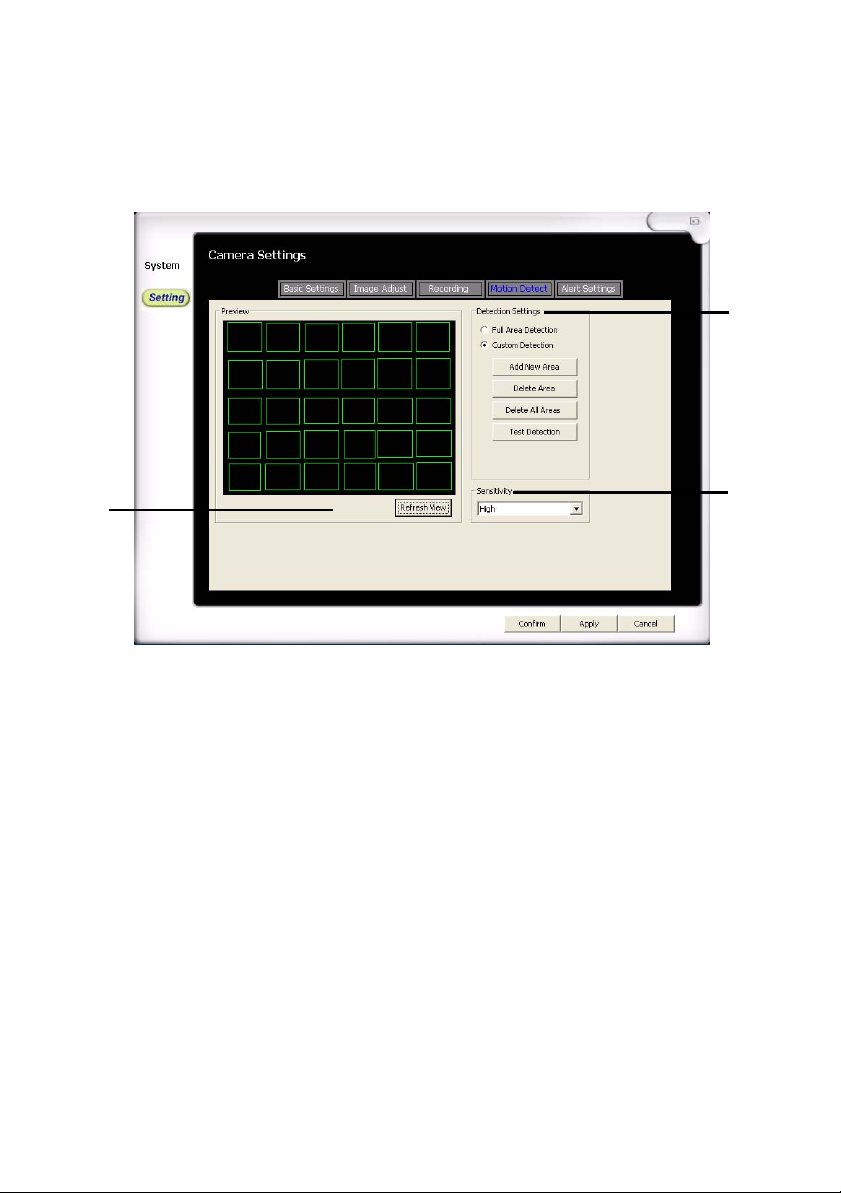
The Motion Detect tab will be available if the Surveillance Mode is set to
Triggered. This particular area allows users to customize sections of
detection and the sensitivity.
2
1
Figure 44. Motion Detect
1. Preview: Hit the Refresh View button to refresh the image
2. Detection Settings: Allows custom areas to detect on the displayed
screen
Full Area Detection: Detects all areas on the screen
Custom Detection: Detects user created detection blocks
Add New Area: Creates a new block to detect. Hold down the
right mouse button over the displayed screen area to create a
new block
Delete Area: Select a block on the displayed screen and hit this
button to delete it
Delete All Areas: Deletes all blocks on the displayed screen
Test Detection: Test the detection by moving an object in front of
the camera, the blocks should change color when it detects
motion
3. Sensitivity: Adjust the sensitivity of the motion detection
3
48
Page 55
Alert Setting 0
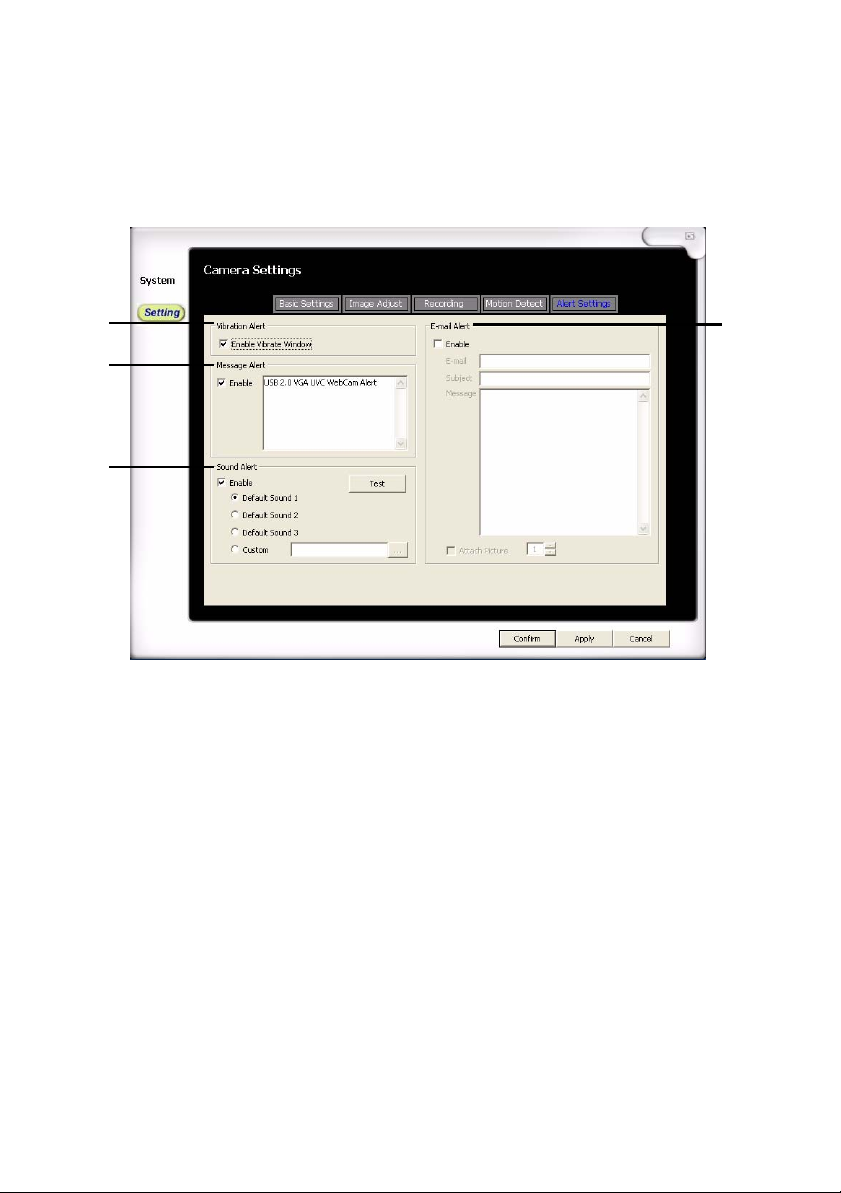
This section will be available if the recording option is set to “Triggered.”
This particular area allows users to set notification options in the event
the viewer detects motion.
1
2
3
Figure 45. Alert Setting
1. Vibration Alert: When enabled, it vibrates the whole viewer when
motion is detected
2. Message Alert: When enabled, it prompts a message alert on
viewer when motion is detected
3. Sound Alert: When enabled, it will playback the chosen sound when
motion is detected
4
4. E-mail Alert: When enabled, a message will be sent based on the
information filled out
49
Page 56

50
Page 57
Appendix A
Specifications
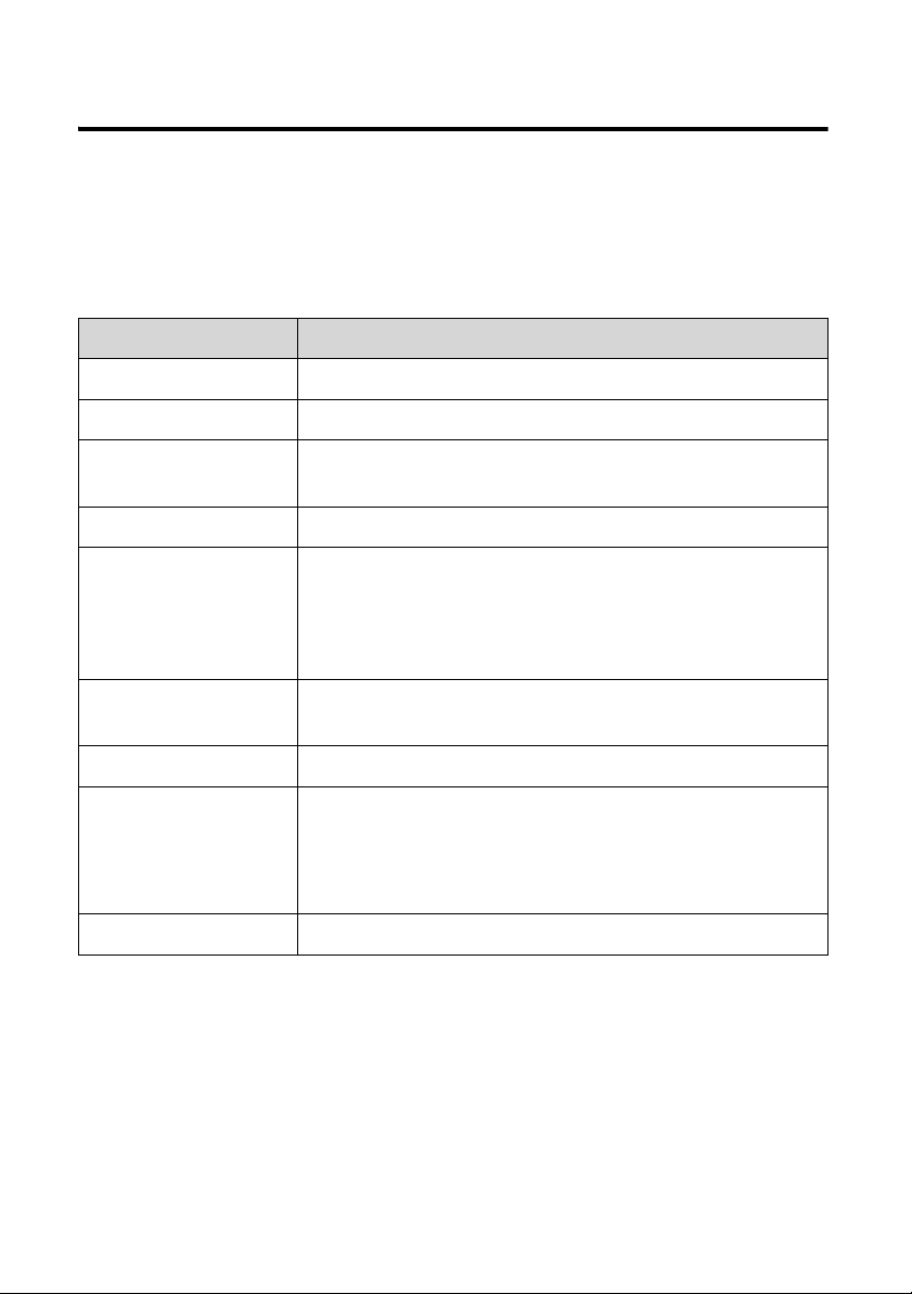
Wireless NVR Camera
Item Description
Frequency 2.4GHz
Antenna Dipole antenna
Transmission
distance
Modulation GFSK
Lens FNO=2.0+/-5% (INFINITE)
Dimensions 7.5cm (excluded antenna) x 4.5cm x 2cm (base
Weight 60 Grams
Power a) DC5V, 380mA
300 M (L-O-S/ without interference)
Vertical:38.9°
Horizontal:50.5°
Diagonal:61.3°
extended is 6.5cm)
b) Rechargeable LI-MH battery: 3.7V, 920 mA/H
Full charge time: 3.5 Hours/Operating time: about
3.5 Hours
0
Connector Mini. USB jack
51
Page 58
USB NVR Receiver
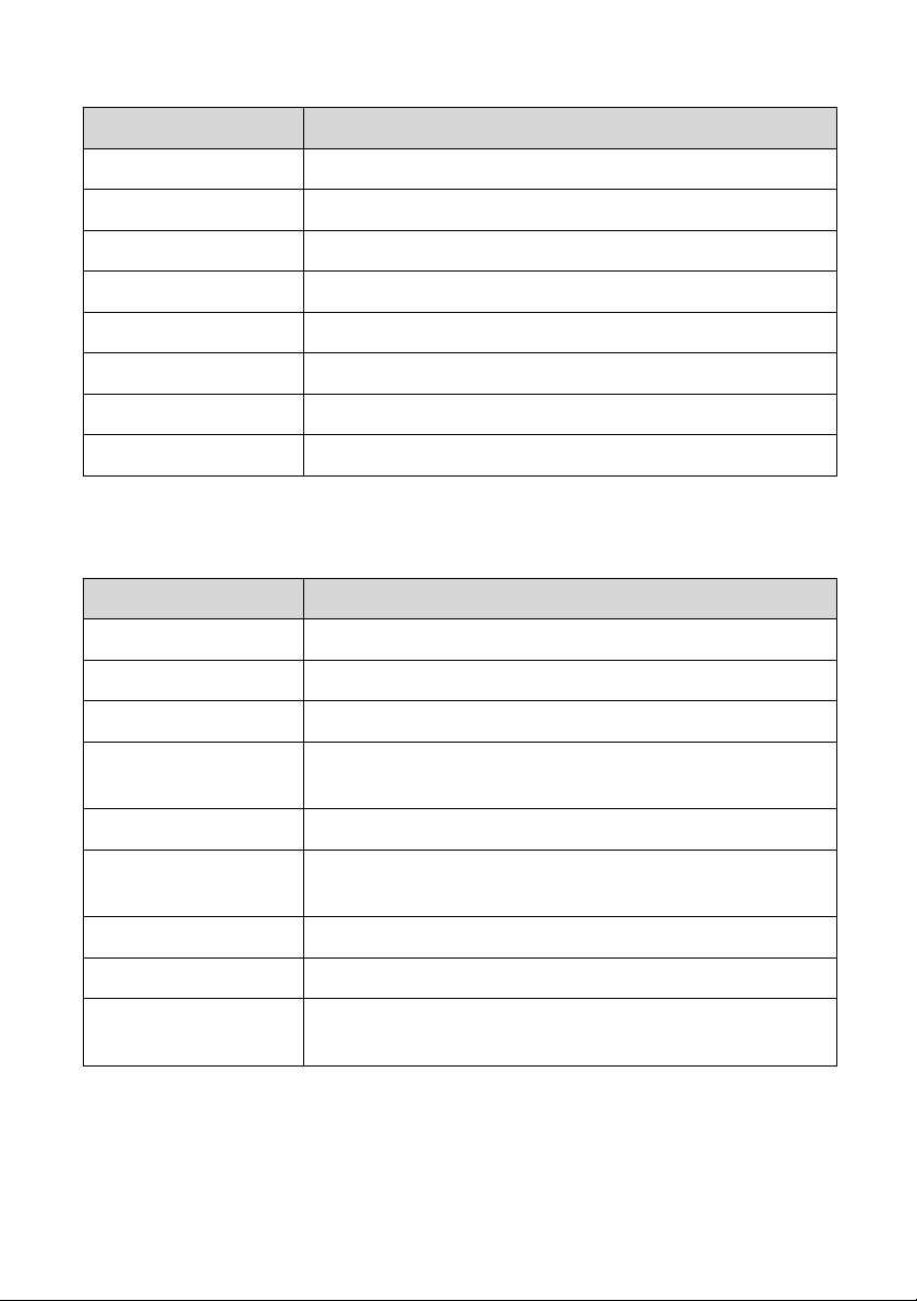
Item Description
Frequency 2.4GHz
Antenna Dipole antenna
Modulation GFSK
Wall mount +/- 45°, angle is adjustable.
Dimensions 6.8cm (excluded antenna length) x 3.0cm x 1.2cm
Weight 15 grams
Power USB bus power
Connector USB output
Functions
Item Description
No. of camera 4
Split display mode 1, 4
Operation Mouse/ keyboard
Simultaneous
operation
Video compression MPEG-4/J-MPEG dual video stream
Display resolution
(VGA)
Display frame rate 1 Channel 15fps/ 4 Channel 30fps
Color 24-bit RGB
Net Surveillance IE browser (1CH video) with PC surveillance
52
snapshot/ monitor/ motion detect/ alert/ record/ IE
remote surveillance/ time stamp
640 x 480
software.
Page 59
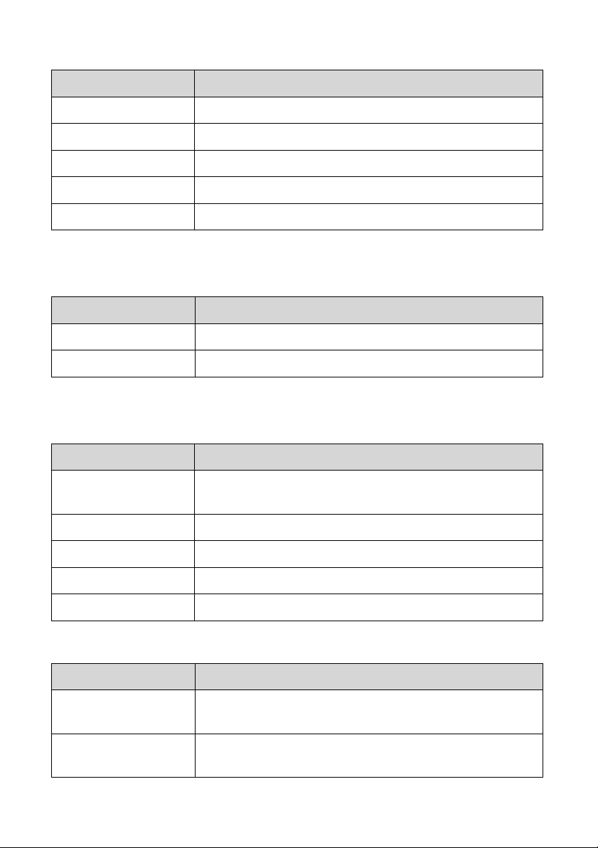
Record
Item Description
Resolution VGA: 640x480 / QVGA: 320x240
Frame rate VGA: 15 fps / QVGS: 30 fps
Recording quality Detect Mode: 5 levels
Motion recording Yes, 1 event/ max. 300 KB
Email-recording 2 ~ 5 pictures (programmable only for pictures)
Playback
Item Description
Search mode Smart search by file/ event/ channels
Playback speed Pause, x1, x2, x4, x8, x16
Alarm/ motion
Motion detection: 24 (6x4) motion zones
Motion detection
sensitivity
No. of alarm inputs 4
No. of alarm output 1
Alarm type Video Motion detection
Sound alert 4 (default 1~3 + custom)
Event
Item Description
Motion Recorded
Event
Event source Motion detection and discontinued record (picture to
High/ Medium/ Low
Max. 300 KB/event, 1GB HD for about 3000 events
show last event)
53
Page 60
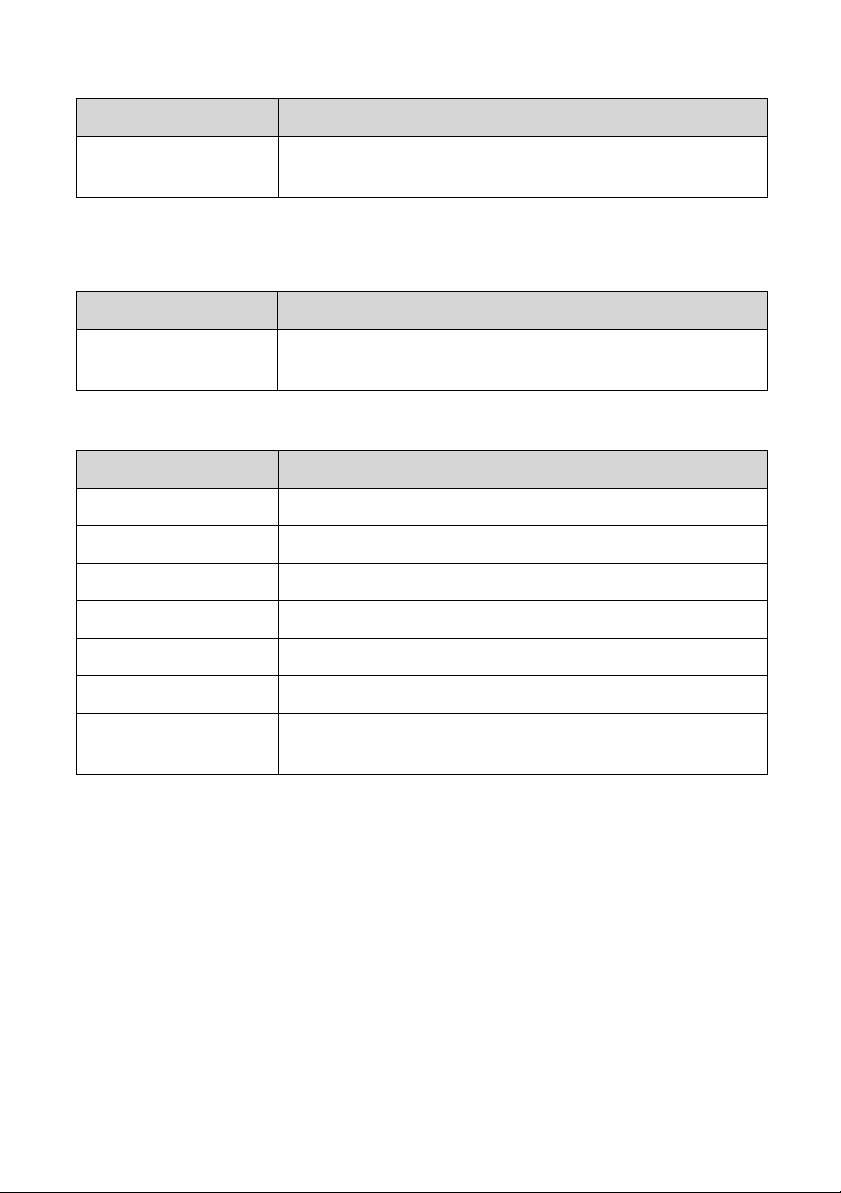
IE browser
Item Description
Remote viewing IE, suggested resolution: VGA: 640x 480 (one
channel)
Backup
Item Description
PC Hard disk Record video on PC hard disk, 1GB HD for about
3000 events
PC System Need (Suggested)
Item Description
CPU Pentium 4, 2.0 GH z or ab ov e
RAM 1GB or above
NET connector RJ45
Resolution 1024 x 768 (24 bits)
Network Camera 1 pc to 4 pcs
Window Office Windows XP, VISTA, or Window 7
Windows Media
Player
54
Windows Media Player 9 or above
Page 61

Certification 0
FCC Interference Statement 0
This equipment has been tested and found to comply with the limits for a
Class B digital device, pursuant to Part 15 of the Federal Communication
Commission Rules. These limits are designed to provide reasonable
protection against harmful interference in a residential installation.
This equipment generates, uses and can radiate radio frequency energy
and, if not installed and used in accordance with the instructions, may cause
harmful interference to radio communications. However, there is no
guarantee that interference will not occur in a particular installation. If this
equipment does cause harmful interference to radio or television reception,
which can be determined by turning the equipment off and on, the user is
encouraged to try to correct the interference by one of the following
measures:
Adjust or relocate the receiving antenna.
Increase the separation between the equipment and receiver.
Connect the equipment into an outlet on a circuit differen t from that to
which the receiver is connected.
Consult the dealer or an experienced radio/TV technician for help.
FCC Caution: To assure con tin ued co mp lia nce, any changes or
modifications not expressly approved by the party responsible for
compliance could void the user's authority to operate this equipment.
(Example - use only shielded interface cables when connecting to computer
or peripheral devices).
55
Page 62

FCC Radiation Exposure Statement 0
This equipment complies with FCC RF radiation exposure limits set forth for
an uncontrolled environment. This equipment should be installed and
operated with a minimum distance of 20 centimeters between the radiator
and your body.
This transmitter must not be co-located or operating in conjunction with a ny
other antenna or transmitter.
The antennas used for this transmitter must be installed to provide a
separation distance of at least 20 cm from all persons and must not be colocated or operating in conjunction with any other antenna or transmitter.
This device complies with Part 15 of the FCC Rules. Operation is subject to
the following two conditions:
This device may not cause harmful interference.
This device must accept any interference received, including interference
that may cause undesired operation.
FCC ID: YS8-ALM-A811 & A812 Made In Taiwan
56
0681
Page 63

Troubleshooting 0
1: The camera and receiver will not pair. Why?
A: Check that both devices are turned on and the antennas are extended. Try
pairing the camera and receiver when they are close to each other before
moving the camera to a specific location.
2: Why are some of the cameras and/or screen controls not accessible?
A: Some of the controls can only be accessed when in single screen mode.
3: Why can I not access the setup and playback options?
A: The setup and playback options are disabled when in detection or web
server mode.
4: Why can’t I pan, tilt, and/or zoom?
A: The camera does not support pan, tilt, and/or zoom functions.
5: The camera and receiver are paired, but the signal is very low. Why?
A: Make sure that there are no objects that coul d be blocking or weakening the
signal. Adjusting the antenna or elevating the camera and receiver can also
improve signal strength.
6: I don’t have static IP address, can I use DDNS?
A: Yes, the programs supports access through an IP address or a DDNS
address.
7: Why does the viewer not start recording after going into detection mode?
A: Check the channel’s recording setup. Make sure that the recording options
are correct. If it is set to full-time, it should record all the time. If it is set to
triggered, it will record only when camera detects change in image displayed.
Check that the detection area and sensitivity are set to the applicable settings.
8: When the web server is enabled, I can not view the image on a remote
computer. Why?
A: Make sure the local area connection does not have a firewall blocking that
particular program and that the IP addr ess is correct.
57
Page 64

9: What does “Can not connect to following channel(s): CH**” mean?
A: The viewer can not detect the IP camera. Make sure that your network is
configured correctly.
10: What does “Can not import to the following channel(s): CH**” mean?
A: The web server could be conflicting with another IP address. Check the IP
address assignment on all your network devices.
11: What does “No buffer space error” and “Virtual RAM insufficient” mean?
A: Your computer could be running low on resources. Typically these errors
occur when the RAM is insufficient. Upgrading your memory will most likely
solve this issue. The recommended memory specifications are 1 GB of RAM.
58
 Loading...