

Page 1
ALM Surgical Equipment Inc.
Prismavision
TM
/PrismaCom
TM
Installation and User Manual
Printed in U.S.A. PRX-95102 Rev. A 5/99
ALM Surgical Equipment, Inc. 1820 North Lemon Street Anaheim, CA 92801 (714)578-1234 / (800)842-2555 / FAX (714)578-1228
Page 2

5/14/99
Table of Contents
Warranty .............................................................................................................................. 1
ALM Installation Guidelines ................................................................................................ 2
Technical Specifications ...................................................................................................... 3
Mounting the Prismavision Power Supply Box...................................................................... 4
Wiring Diagram-PrismaVision .............................................................................................. 5
Wiring Diagram-PrismaCom ................................................................................................ 6
Peripheral Connections to Prismavision Power Supply Box .................................................. 7
Installing the VZ Camera ...................................................................................................... 8
Adapting the Camera to the PRC Light ................................................................................ 9
Power Supply Operation ...................................................................................................... 10
Hand Control Operation ...................................................................................................... 11
Feature Definitions .............................................................................................................. 12
Image Orientation ................................................................................................................ 13
Foot Control ........................................................................................................................ 13
Sterilizable Handle Placement and Removal ........................................................................ 14
Sterilization Procedure ........................................................................................................ 14
Cleaning .............................................................................................................................. 14
Spare Parts ............................................................................................................................ 15
Page 3

Warranty
Video equipment is guaranteed for a period of one (1) year,
beginning on the date the equipment leaves our depot, with the
exception of normal, usable and consumable parts. This warranty
applies exclusively to the supply of parts and labor to replace those
recognized defective by ALM. This concerns all items of equipment
operated under normal conditions.
Any questions relating to the above mentioned warranty should be
directed to the ALM Customer Service department or the ALM
Project Specialist for your facility.
ALM Surgical Equipment, Inc.
1
Page 4

5/14/99
ALM Installation Guidelines
The installation of the PRX Prismavision/PrismaCom video system is an important function. It requires
close cooperation with all members of the team. The following serves as policy guidelines:
Project Specialist
1. Complete and submit a video camera pre-installation checklist.
2. Assist hospital in ordering all parts necessary to insure proper installation of
Prismavision/PrismaCom system.
3. Advise hospital of their responsibilities for the installation of the Prismavision/PrismaCom system.
(O.R. Supervisor, Engineering).
4. Advise Customer Service and Technical Specialist of hospitals’ preferred date of installation.
5. Provide in-service as required for hospital personnel.
Hospital
1. Hospital is responsible for installation of 110 Volt power supply ( Prismavision only) on designated
wall, to meet NEC (National Electric Code). Also, the routing of ceiling cable from power supply
to suspension tube following all electrical codes.
2. Provide personnel to complete the installation.
Technical Specialist
1. Check equipment to insure that proper items are present before installation is started.
2. Supervise overall installation of Prismavision/PrismaCom video camera system.
3. Interface with customer and Project Specialist to answer technical questions during and
following the installation.
Acknowledged by:
Hospital ________________________________ Date ______
Project Specialist _________________________________ Date ______
2
Page 5

5/14/99
3
Technical Specifications
PRISMAVISION PRISMACOM
Signal NTSC
Sensor 1/3" hyper HAD CCD
Pixels 768 (H) x 494 (V) = 380,000
Lens 12x zoom 12mm NF mount
Focus mechanism Auto Fixed
Focal length (mm) 5.4 to 64.8 25
Aperture F 1.8-2.7 F5.6
Anti flicker Integrated
Location Center of cupola, in sterilizable handle
Horizontal definition 460 470
White balance 3200K, 5600K, one-push, ATW 3200K - 5600K manual
Signal/noise ratio (dB) 48
Zoom foot pedal Option None
Control box size (mm) Wall mounted, H300/L170/ D110 None
Outputs Composite, Y/C
Power requirements DC 6-12 V, 2.4 to 3.4W DC 12 V, 2.3W
Minimum light level 7 lux (f1.8) 4.5 lux, (f 1.2)
Electronic shutter speed 1/60 - 1/10,000s Normal ,1/1001, 1/4000, flickerless
NOTE: For optimum video image quality, it is recommended that the monitor have a resolution of
600 lines or more and a 75 ohm BNC input connection.
The PrismaVision video camera system is made up of:
1. Video zoom camera with sterilizable handle.
2. Video power supply with remote control and ceiling cable.
The PrismaCom video camera system is made up of:
1. Video fixed focus camera with sterilizable handle.
2. Video power supply (integrated in surgical light main arm) and ceiling cable.
Page 6
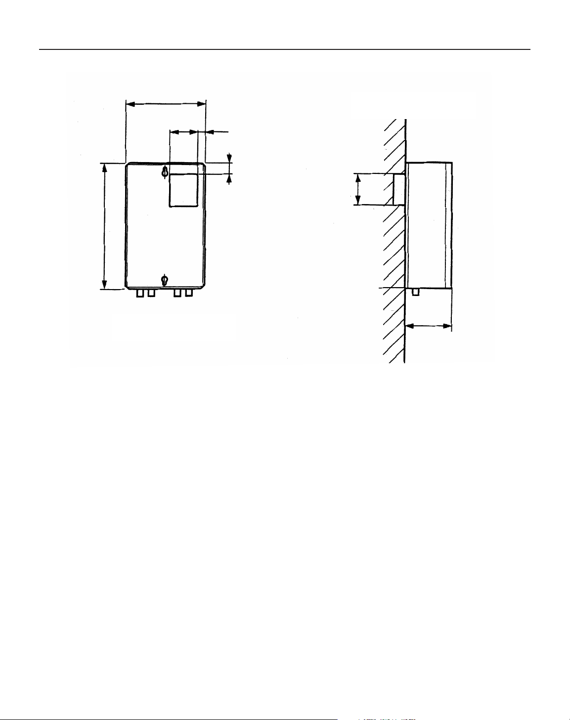
Mounting the Prismavision Power Supply Box
5/14/99
4
Caution: Be sure that all electrical power is turned off before beginning installation.
1. Remove two cover screws on power supply box. Pull front cover away from box frame.
Disconnect wiring and put front cover aside.
2. Surface mount the box frame on the wall five feet above the floor. Install a 2-gang box near
opening of box frame.
3. Pull #14 wires from the supply voltage to the power supply box.
4. Pull ceiling cable (supplied by ALM) from the suspension tube to the power supply box.
Use 3/4” conduit.
5. Make electrical connections (schematic on following page).
6. Re-connect front cover wiring and fasten front cover to box frame.
7.8 IN.
.7 IN.
2.75 IN.
1.1 IN.
12.6 IN.
4.5 IN.
3.2 IN.
View of box frame
Side view of box
Page 7

Wiring Diagram-Prismavision
5/14/99
5
1. Connect male and female BNC connectors.
2. Connect red leads.
3. Connect black and yellow leads.
1. Connect black lead to ‘DATA’ terminal.
2. Connect red lead to ‘12 V’ terminal.
3. Connect coax braid to ‘GROUND’ terminal.
4. Connect video core to ‘VIDEO’ terminal.
5. Connect 110V feed to voltage input terminals.
Bypass 12 VDC
power supply for
fixed focus camera.
Page 8

5/14/99
6
Wiring Diagram-PrismaCom
1. Connect male and female BNC connectors.
1. Ceiling cable termination point can be located on the surgical light
dimmer control panel or a separate designated area in the operating
room. A location close to the video monitor is ideal.
2. The ceiling cable terminates with a male BNC connector. The panel
mount BNC adapter is not provided by ALM.
12 VDC power supply
is located in upper
main arm. Connections
are made at the factory.
Maximum video line run without amplifier.
Page 9

5/14/99
7
Peripheral Connections to Prismavision Power Supply Box
Align with groove and push
in to lock.
Push BNC connector in and
rotate clockwise.
Peripheral connections
Monitor
Prismavision power
supply box
Hand Control
Foot Control
Page 10

Installing the VZ Camera
8
2. Mount the VZ camera
to its mounting plate.
3. Connect cable.
4. Fasten connector in place
using two screws.
1. Remove the CFF
camera and
disconnect the
cable clamp
and cable.
5. Remove VZ camera
from its mounting plate.
6. Mount VZ mounting plate to
lighthead, using 3 screws.
7. Mount VZ camera back onto VZ mounting
plate.
8. Bypass CFF power supply board in upper
main arm (see page 5).
9. Turn on VZ power supply and check system
for proper operation.
Page 11

5/14/99
9
Adapting the Camera to the PRC Light
Page 12

Power Supply Operation
Located at the bottom of the power supply box are the hand control, monitor (s) and foot control ports.
Each desired component must be properly connected before turning the system on. To activate the
Prismavision camera system press the green power button located on the power supply. The
Prismavision system will “”wake-up” in the automatic focus, white balance and exposure mode.
To turn the Prismavision off, press the green power button.
10
Power Supply Operation
Page 13

11
Hand Control Operation
A. ZOOM ADJUSTMENT: Enlarges or reduces
the image.
B. FOCUS ADJUSTMENT: For manual adjustment
of image sharpness.
C. EXPOSURE ADJUSTMENT: Camera iris
adjustment. Used to control intensity of light
received by sensor. ‘+’ opens iris, ‘-’ closes iris.
D. AUTO INDICATOR LIGHT: Indicates that
function is in automatic mode. This light will
go off when manual override is activated.
E, F. AUTO FUNCTION: Restores function to
automatic mode. Green Indicator light (D) will
be on.
G. MEMORY FUNCTION: Stores custom settings
of zoom, focus, exposure and white balance.
H. PRESET 1: To set and/or recall a
memorized setting.
I. PRESET 2: To set and/or recall a
memorized setting.
J. AUTO WHITE BALANCE: White balance
(color) Adjustment.
Hand Control Operation
When the Prismavision system is turned on, (pg. 10) the hand control will “wake-up” in the automatic
function mode. This will be indicated by the green auto indicator lights. The only manual function
required is the zoom adjustment.
Page 14

12
Feature Definitions
ZOOM ADJUSTMENT - Pressing and holding the + or - function will adjust the size of the image on
the monitor.
FOCUS ADJUSTMENT - The green light indicates that the focus adjustment is in the automatic mode.
The image will remain in focus as the picture is zoomed in or out or the light head is repositioned. The
user can manually adjust the focus by pressing and holding the + or - key. When these keys are
pressed, the green indicator light will go out. To reset the auto focus feature, press and hold the auto
focus button until the green light turns on.
EXPOSURE ADJUSTMENT - The green light indicates that the exposure adjustment is in the automatic
mode. The proper light exposure will remain correct as the light intensity changes. The user can manually adjust the exposure (iris) by pressing and holding the + or - key. When these keys are pressed, the
green indicator light will go out. To reset the auto exposure feature, press and hold the auto exposure
button until the green light turns on.
AUTO FUNCTION - These buttons restore the corresponding function to automatic. Press and hold the
button until the green light turns on.
MEMORY FUNCTION - This function allows the user to memorize a specific camera setting. First the
settings (zoom, focus, exposure and/or white balance) are established. To store these settings simultaneously press the memory key and Preset 1 or Preset 2.
PRESET 1 and 2 - Recalls or establishes memorized settings. To recall a setting simply press the appropriate button and the system will automatically recall the desired settings. These settings will remain
stored until new settings are programmed, or until the system is turned off.
AUTO WHITE BALANCE - The “white balance” function is used to balance the video image colors
according to the dominant color in the field viewed. Prismavision has an automatic white balance feature calibrated to the PrismAlix and Prismatic light. The user can manually set the white balance by
focusing the Prismavision camera on a uniform color (white sheet of paper) and pressing and holding
the auto white balance button for 10 to 15 seconds until the image changes color. To reset the default
auto white balance, press and release the same key.
Page 15

13
Image Orientation
Foot Control
Image Orientation
The on screen image can be oriented by rotation of the Prismavision or Prismacom handle assembly.
This allows the user to place the image in the exact position desired.
Foot Control
The foot control is optional. The foot control has two functions, zoom in and zoom out. The right pedal
reduces image size and the left pedal increases image size. The foot control connects directly to the
Prismavision Power Supply Box and operates independent of the hand control.
Page 16

14
Sterilizable Handle Placement and Removal
Sterilizable Handle Placement and Removal
To place the sterilizable Prismavision handle, simply slide the handle over the gray camera assembly
until you hear the locking mechanism engage (‘click’). To remove the handle press the button located
on the handle and slide off.
Sterilization Procedure
Sterilization Procedure
Avoid ‘FLASH’ cycles. Do not stack handles. Handles should not come into contact with metal.
Prismavision and Prismacom handles are guaranteed for a minimum of 100 cycles.
Gravity-displacement cycles for routine porous and non-porous loads:
Expose temperature and time: 134oC
+
-
4ofor 20 minutes.
(IEC-1988 standards, 601.1 44.7 page 155)
Sterility assurance level, 10
-6
Cleaning
Cleaning
To prevent scratching the lens, avoid abrasive cleaning agents on or around the camera assembly. An
anti-static cleaning agent is recommended. Apply the cleaning solution to the area to be cleaned and
wipe dry with a soft silk cloth.
NOTE: The camera must never be disinfected by immersion or sterilization.
Page 17

Spare Parts
50076 Prismavision Camera Sterilizable Handle
50072 Prismacom Camera Sterilizable Handle
50169 Prismacom Camera Sterilizable Handle, (box of 5)
50090 15m Prismavision Ceiling Cable
50091 25m Prismavision Ceiling Cable
50153 15m Prismacom Ceiling Cable
50154 25m Prismacom Ceiling Cable
50155 15m Prismavision Ceiling Cable for Multi-room Complex
50156 25m Prismavision Ceiling Cable for Multi-room Complex
50157 15m Wall to Multi-room Self Contained Control Box, Cable
50158 25m Wall to Multi-room Self Contained Control Box, Cable
50159 Wall Plate, Prismavision
50160 Wall Plate, Prismcom
50151 Foot Pedal
50074 Hand Pendant
50086 Prismavision Camera Only
50075 Prismacom Camera Only
5/14/99
Printed in U.S.A. PRX-95102 Rev. A 5/99
ALM Surgical Equipment, Inc. 1820 North Lemon Street Anaheim, CA 92801 (714)578-1234 / (800)842-2555 / FAX (714)578-1228
15
Spare Parts
To order, Contact:
ALM Surgical Equipment, Inc.
Customer Service Department
1820 North Lemon Street
Anaheim, CA92801-009
1-800-842-2555 or 1-714-578-1234
 Loading...