

Page 1

INSTALLATION AND
OWNER’S MANUAL
MODEL SPS-50
GATE OPERATOR
STANDBY POWER SUPPLY
Serial #:
Date Installed:
Your Dealer:
107887
READ THIS MANUAL
CAREFULLY BEFORE
INSTALLATION OR USE
1
Page 2
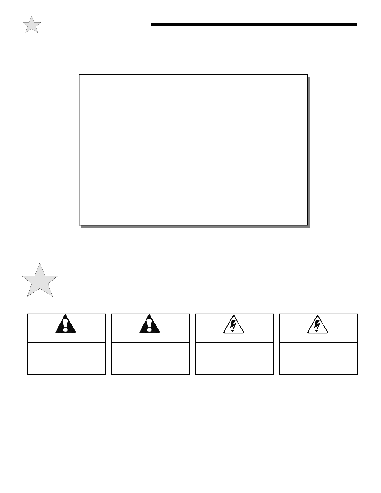
TABLE OF CONTENTS
Pre-Installation Notes .............................................................. 3
Installing the SPS-50................................................................ 4
LED Indicators ............................................................... 5
Electrical Connections.................................................. 5
Testing............................................................................ 5
Battery Maintenance ..................................................... 6
Wiring Diagram .............................................................. 7
Technical Specifications ......................................................... 8
Warranty.................................................................................... 8
READ THESE STATEMENTS CAREFULLY AND FOLLOW THE
The Warning and Caution boxes throughout this manual are there to protect you and
your equipment. Pay close attention to these boxes as you follow the manual.
WARNING
Indicates a MECHANICAL
hazard of INJURY OR
DEATH. Gives instructions
to avoid the hazard.
INSTRUCTIONS CLOSELY.
CAUTION
Indicates a MECHANICAL hazard
of DAMAGE to your gate, gate
operator, or equipment. Gives
instructions to avoid the hazard.
WARNING
Indicates an ELECTRICAL
hazard of INJURY OR
DEATH. Gives instructions
to avoid the hazard.
CAUTION
Indicates an ELECTRICAL hazard
of DAMAGE to your gate, gate
operator, or equipment. Gives
instructions to avoid the hazard.
2
Page 3
PRE INSTALLATION NOTES
The Allstar Standby Power Supply is designed to provide backup power to a gate operator when the main AC supply voltage is
interrupted or disconnected. It eliminates the need for a separate
motor and control circuit to be mechanically attached to the gate
operator. The SPS-50 will provide the power and a signal to the
gate operator to open the gate and leave it open until the main
power is restored. Once the main power is restored, the SPS-50
will provide a signal to the gate operator and the operator will
close (if a timer to close is used). It is not designed to
continuously cycle the gate operator. Many local building codes
require this type open only back-up vs. a continuos cycle backup.
NOTICE
BEFORE ATTEMPTING INSTALLATION,
READ THIS MANUAL CAREFULLY SO YOU WILL BE
THOROUGHLY FAMILIAR WITH THE FEATURES OF
THE ALLSTAR STANDBY POWER SUPPLY AND ITS
PROPER INSTALLATION.
The SPS-50 consists of control box and a battery pack. The
SPS-50 control box senses the main power, charges the battery
pack, converts the DC battery voltage to AC voltage (to power
the operator) and provides control signals to activate the
operator when the main power is interrupted. Additionally, the
SPS-50 control box has a set of relay outputs that are activated if
a low battery capacity is detected. These contact may be
connected to an alarm system to alert the end user that battery
maintenance is required.
Gate operators are designed to start and move gates weighing as
much as 1000 pounds or more and are capable of producing high
levels of force. It is important in the design of the total gate
system that designers, installers and users be aware of the
hazards that may be associated with the IMPROPER design,
installation and use of vehicular gate systems and gate operators.
As the designer and installer of the GATE SYSTEM, you must
advise the purchaser on the proper use of the gate system. You
also have the primary responsibility of insuring that ALL
possible operational hazards have been considered and
eliminated. YOU MUST ADVISE and WARN the purchaser
and the ultimate user of ANY HAZARDS that you have not
been able to eliminate.
NOTICE
THE IMPORTANT SAFEGUARDS AND
INSTRUCTIONS IN THIS MANUAL CANNOT COVER
ALL POSSIBLE CONDITIONS AND SITUATIONS WHICH
MAY OCCUR DURING ITS USE. IT MUST BE
UNDERSTOOD THAT COMMON SENSE AND CAUTION
MUST BE EXERCISED BY THE PERSON(S)
INSTALLING, MAINTAINING AND OPERATING THE
EQUIPMENT DESCRIBED HEREIN. DO NOT USED THIS
EQUIPMENT FOR ANY OTHER THAN ITS INTENDED
PURPOSE - PROVIDING TEMPORARY POWER TO A
GATE OPERATOR.
WARNING!
TO REDUCE THE RISK OF SEVERE INJURY OR
DEATH: READ AND FOLLOW ALL
INSTALLATION INSTRUCTIONS AND GATE
SYSTEM DESIGN PARAMETERS PROVIDED
WITH THE GATE OPERATOR.
Advise the purchaser to test the operation of the SPS-50
monthly and record the date tested on the log provided below.
WARNING HIGH VOLTAGE
ONLY A QUALIFIED TECHNICIAN SHOULD SERVICE THIS GATE OPERATOR
PERIODICALLY TEST SENSITIVITY OF OVERLOAD
*** READ MANUAL ***
LOG DATE BATTERY TEST
DATE TESTED DATE TESTED DATE TESTED DATE TESTED
3
DATES
OPERATOR
SERVICED
Figure 1
Page 4

INSTALLING THE SPS-50
The SPS-50 is not weather proof and must be protected from exposure. Ideally, the unit should be located inside the operator, away
from where water might infiltrate the operator. If there is no suitable space inside the operator, it may be located in an electrical
enclosure outside the operator. The battery pack must be connected to the SPS-50 control box with the leads provided. Do not route
low voltage wires in the same conduit as high voltage wires. Follow all local electrical codes or the national electrical code.
The following items are included with the SPS-50:
1. 1- SPS-50 control box
2. 1- SPS-50 battery pack
3. 1- Relay output wire harness
4. 2- AC power in or power out wire harness
5. 1- Warning label
6. 1- Instruction Manual
The SPS-50 consists of control box and a battery pack. Connectors are located on the SPS-50 control box for AC IN, AC OUT,
RELAY and BAT LO. Pre-wired harnesses are provided to mate with these connectors. The black and red wires are used to connect
to the battery pack. The LED’s indicate the status of the main AC voltage and the SPS-50 as follows:
AC ON: Green LED on, AC line voltage present
RELAY: Yellow LED on, relay NO output is closed to common, CM
INV ON: Yellow LED on, the SPS-50 is providing power to the gate operator
LO BAT: Red LED on, the LO BAT relay NO output is closed to common, CM
Refer to the figure below for the location of the connectors and LED’s.
THE SPS-50 IS DESIGNED TO PROVIDE POWER
TO A GATE OPERATOR WHEN THE M AIN AC
POWER IS TURNED OFF. A GATE OPERATOR
CONNECTED TO THE SPS-50 MAY START
UNEXPECTEDLY WHEN THE MAIN AC POWER IS
TURNED OFF. WHEN SERVICING THE GATE
OPERATOR OF THE SPS-50 DISCONNECT THE
WARNING!
BATTERY PACK.
W A R N I N G !
THE SPS-50 PRODUCES LETHAL VOLTAGES.
THE BATTERY PACK IS CAPABLE OF
SUPPLYING HAZARDOUS CURRENT. THE SPS-
50 SHOULD BE INSTALLED BY A QUALIFIED
TECHNICIAN.
WARNING!
DANGEROUS VOLTAGES MAY BE PRESENT
WHEN THE BATTERY PACK IS CONNECTED TO
THE SPS-50 CONTROL BOX. DO NOT CONNECT
THE BATTERY UNTIL INSTRUCTED TO DO SO.
DISCONNECT THE BATTERY PACK BEFORE
SERVICING.
107888
Figure 1: Location of
Connectors and LED’s
4
Page 5

INSTALLING THE SPS-50
Connecting the AC Line Voltage (Main Voltage)
The SPS-50 is designed to provide back-up power to the gate
operator ONLY. Auxiliary devices such as loop detectors, card
readers, phone entry systems, etc., must NOT be connected to
the output of the SPS-50. These devices may overload the
capacity of the SPS-50 and prevent proper gate operation.
WARNING!
RISK OF ELECTROCUTION. DO NOT BEGIN
THE ELECTRICAL CONNECTION
PROCEDURES UNTIL THE POWER IS TURNED
OFF AT THE CIRCUIT BREAKER.
Electrically, the SPS-50 is wired in series with the incoming AC
supply from the breaker box to the operator. The connector
labeled AC IN is connected to the main AC supply. The AC
OUT is connected to the operator.
Refer to the diagram on page 7 for the following:
Connect the incoming AC line to the AC IN as follows:
L - AC Line In (live): Black
N - AC neutral (common): White
G- AC Ground (earth): Green
Connect the outgoing AC line to the AC OUT as follows:
L - AC Line out: Black
N - AC neutral: White
G- AC Ground: Green
Refer to the instructions provided with the operator for the
proper connections to the operators.
Connecting the Relay Outputs
Two sets of relay outputs are available on the SPS-50. The set
marked LO BAT are intended to be alarm contacts to alert of
low battery capacity. These must be connect to a suitable alarm
system (not provided).
The set marked RELAY are connected to the operator as
follows:
CM - Common, connected to the control input common terminal
of the operator
NO - Normally open, connected to the hold open terminal of the
operator
If the operator uses a normally closed control circuit, the NC
contact may be used. Refer to the instructions provided with the
operator for the proper connections to the operator control panel.
Applying Power and Connecting the Battery Pack
Follow the steps below when connecting the battery pack to the
SPS-50:
CAUTION !
DO NOT CONNECT THE BATTERY PACK UNTIL
AC POWER IS TURNED ON. ARCING WILL
OCCUR AND THE SPS-50 WILL ACTIVATE THE
GATE OPERATOR.
1. Turn the main power on. The AC LED on the SPS-50
should be on.
2. Test the operator for several open / close cycles
3. Connect the battery pack to the SPS-50. Connect the red
wire to the red terminal on the batter pack and the black
wire to the black terminal on the battery pack
WARNING!: Do not reverse the connections to the battery
pack. Reversing the leads will permanently damage the SPS-50.
Typically, the batteries will require 24 hours of charging time
after installation.
Testing the SPS-50
After the batteries are charged, the SPS-50 may be tested. To
test, turn the main power off and allow the SPS-50 to cycle the
operator. There will be approximately a ten second delay
between the loss of AC power and when the operator starts to
open. After approximately 30 seconds, the SPS-50 will shut
down the power to the operator.
After the completion of the test, turn the main AC power back
on. After approximately ten seconds a reset pulse will be sent to
the operator. If the operator is wired for auto timer to close, it
should close at the end of the time delay period.
The SPS-50 will only provide back-up power for 2-5 cycles
(depending on battery charge, temperature and gate size and
weight). If the battery charge is too low, the SPS-50 will not be
able to develop sufficient voltage to power the gate operator and
the batteries must recharge before additional testing.
A monthly test should be made to ensure proper operation of the
system.
5
Page 6

INSTALLING THE SPS-50
Installing the Warning Labels
The warning labels should be placed to notify service personnel
that the gate operator is connected to a back-up power supply
unit.
107889
Figure 2: Warning Label
Maintenance of Batteries
Typical battery life should be two years, however this will vary
depending on use and climate. Should batteries need replacing,
observe the following:
Servicing of batteries should be performed by personnel
knowledgeable of batteries and the required precautions. Keep
unauthorized personnel away from the batteries.
When replacing batteries replace with the same number and
type. The SPS-50 uses a PowerSonic PS-1270 rechargeable
maintenance free, 12 volt, 7.0 amp/hour battery.
When disconnecting the battery pack from the SPS-50 make
sure main AC power is turned on.
Final Installation Check List
Before leaving the installation:
• Check for any unsafe conditions
• Make sure all covers are replaced on electrical enclosures
• Check for proper installation of sprocket guards and
warning signs
• Test all safety features and safety equipment
• Disable and do not place the gate operator in service if any
unsafe conditions exits
• Review with the owner/end user of the system the proper
operation and safety features of the gate system
• Leave the installation and maintenance manual with the
owner/end user
W A R N I N G !
DO NOT DISPOSE OF BATTERIES IN A FIRE.
THEY MAY EXPLODE. TAKE BATTERIES TO A
RE-CYCLING CENTER.
W A R N I N G !
DO NOT OPEN OR MODIFY THE BATTERY
PACK. RELEASED ELECTROLYTE IS
HARMFUL TO THE SKIN AND EYES AND MAY
BE TOXIC.
W A R N I N G !
A BATTERY CAN PRESENT A RISK OF
ELECTRICAL SHOCK AND HIGH SHORT-
CIRCUIT CURRENT. WHEN WORKING WITH
BATTERIES, REMOVE WATCHES, RINGS OR
OTHER METAL OBJECTS; USE TOOLS WITH
INSULATED HANDLES; DO NOT LAY TOOLS
OR METAL OBJECTS ON TOP OF BATTERIES.
6
Page 7

107890
Figure 3: Wiring Diagram
RISK OF ENTRAPMENT.
OPERATOR CONNECTED TO THE SPS-50 MAY START UNEXPECTEDLY WHEN THE MAIN AC POWER IS TURNED OFF.
THE SPS-50 IS DESIGNED TO PROVIDE POWER TO A GATE OPERATOR WHEN THE MAIN AC POWER IS TURNED OFF. A GATE
7
Page 8

TECHNICAL SPECIFICATIONS
INPUT VOLTAGE:
SURGE PROTECTION:
BATTERY:
RECHARGE TIME:
105 - 125 VAC OUTPUT VOLTAGE: 115 VAC ± 10%
MOV, TRANZORB OUTPUT FREQUENCY: 60 HZ
24 VDC, 7 AH OUTPUT CURRENT: 5 AMPS
8 HOURS SURGE CURRENT: 9 AMPS
OUTPUT POWER: 500 WATTS
SURGE POWER: 1000 WATTS
Specifications subject to change without notice. Consult the factory.
RELAY OUTPUT: DPDT, 2 AMPS
DO NOT EXCEED THE OUTPUT CAPACITY OF THE SPS-50.
CONNECTING A MOTOR LOAD LARGER THAN RECOMMENDED WILL
CAUTION !
DAMAGE THE SPS-50 AND VOID THE WARRANTY.
Manufacturer’s Limited Warranty
Linear LLC warrants its Allstar brand SPS-50 to be free from defect in material and workmanship for a period of one (1) year from the date
of purchase for single family home or for multi-family and commercial use. To obtain service contact your dealer.
To obtain service under this warranty the buyer must obtain authorization instructions for the return of any goods from Linear before
returning the goods. The goods must be returned with complete identification, with copy of proof-of-purchase, freight prepaid and in
accordance with Linear’s instructions or they will not be accepted. In no event will Linear be responsible for goods returned without proper
authorization or identification.
Goods returned to Linear for warranty repair within the warranty period, which upon receipt by Linear are confirmed to be defective and
covered by this limited warranty, will be repaired or replaced at Linear’s sole option, at no cost and returned pre-paid. Defective parts will
be repaired or replaced with new or factory rebuilt parts at Linear’s sole option.
This limited warranty does not cover non-defect damage, damage caused by unreasonable use, damage caused by improper installation or
care, vandalism or lightning, fire or excessive heat, flood or other acts of God (including, but not limited to misuse, abuse or alterations,
failure to provide reasonable and necessary maintenance), labor charges for dismantling or reinstalling a repaired or replaced unit, or
replacement batteries.
These warranties are in lieu of all other warranties, either expressed or implied. All implied warranties of merchantability and/or fitness for a
particular purpose are hereby disclaimed and excluded. Under no circumstances shall Linear be liable for consequential, incidental or special
damages arising in connection with the use or inability to use this product. In no event shall Linear’s liability for breach of warranty, breach
of contract, negligence or strict liability exceed the cost of the product covered hereby. No person is authorized to assume for Linear any
other liability in connection with the sale of this product.
This warranty gives you specific legal rights. You may also have other rights which vary from state to state. Warranty effective after
October 1st, 2007.
For Information:
877-441-9300 800-421-1587 www.allstarcorp.com
8
P/N 190-107884 Rev. D August 2007 Copyright © 2007 Linear LLC
 Loading...