


J3500
INSTALLER: Place this manual in the plastic envelope provided and permanently
attach to the wall near the pushbutton.
INSTALLATION AND
OWNER’S MANUAL
3000 SERIES
Residential Vehicular Garage Door Operator
MODELS: 3000, 3500, 3500-P & J3500
As of date of manufacture,
meets all ANSI/UL 325
Safety Requirements for
Vehicular gate operators
Serial #:
Date Installed:
Your Dealer:
107063
READ THIS MANUAL
CAREFULLY BEFORE
INSTALLATION OR USE
1
TABLE OF CONTENTS
Product Features ....................................................................................2
Component Identification/Tools Required............................................4
Section A: Assembly Instructions........................................................5
Section B: Installation Notes ................................................................6
Section C: Installing the Operator ........................................................7
Identify Your Door Type..............................................................7
Mounting the Front Bracket........................................................8
Mounting the Power Head ..........................................................9
Door Arm Installation................................................................10
Pushbutton Connection............................................................11
Section D: Auxiliary Equipment..........................................................13
Installation of All-Clear .............................................................13
Installation of Radio Controls ..................................................15
Installation of Deluxe Wall Station...........................................16
Operating Parameters ..........................................................................16
Section F: Operation and Adjustment Instructions...........................17
Safety Notes ..............................................................................17
Testing the Sensitivity ..............................................................18
Testing the Reversing System .................................................18
Testing the All-Clear .................................................................19
Operating the Deluxe Wall........................................................19
Operator Wiring Diagram .....................................................................20
Auxiliary Equipment Wiring Diagram..................................................21
Installation Checklist............................................................................22
Troubleshooting Guide ........................................................................23
READ THESE STATEMENTS CAREFULLY AND FOLLOW THE
The Warning and Caution boxes throughout this manual are there to protect you and
your equipment. Pay close attention to these boxes as you follow the manual.
WARNING
Indicates a MECHANICAL
hazard of INJURY OR
DEATH. Gives instructions
to avoid the hazard.
INSTRUCTIONS CLOSELY.
CAUTION
Indicates a MECHANICAL hazard
of DAMAGE to your gate, gate
operator, or equipment. Gives
instructions to avoid the hazard.
WARNING
Indicates an ELECTRICAL
hazard of INJURY OR
DEATH. Gives instructions
to avoid the hazard.
2
CAUTION
Indicates an ELECTRICAL hazard
of DAMAGE to your gate, gate
operator, or equipment. Gives
instructions to avoid the hazard.

PRODUCT FEATURES
The purpose of this booklet is to provide assembly,
installation and operation information concerning Allstar
Residential Garage Door Openers and related Accessory
Products.
NOTICE
IT IS IMPORTANT THAT THIS
INSTRUCTION MANUAL BE READ AND
UNDERSTOOD COMPLETELY BEFORE
INSTALLATION OR OPERATION IS
ATTEMPTED.
NOTICE
THE IMPORTANT SAFEGUARDS AND
INSTRUCTIONS IN THIS MANUAL CANNOT
COVER ALL POSSIBLE CONDITIONS AND
SITUATIONS WHICH MAY OCCUR DURING
ITS USE. IT MUST BE UNDERSTOOD THAT
COMMON SENSE AND CAUTION MUST BE
EXERCISED BY THE PERSON(S) INSTAL-
LING, MAINTAINING AND OPERATING
THE EQUIPMENT DESCRIBED HEREIN. DO
NOT USE THIS EQUIPMENT FOR ANY
OTHER THAN ITS INTENDED
PURPOSE - OPERATING OVERHEAD
GARAGE DOORS.
STANDARD FEATURES:
Sensing System: A built-in sensing system detects
obstructions during door operation. If in the downward (close)
travel mode, the Opener will sense an obstruction and reverse
the direction of the door. In the open mode, the Opener will
stop. Since all doors are different, the Sensing System has
independent adjustments for customizing the level of force
required for the normal opening and closing of specified doors.
( Page 18)
Close Limit Switch: In winter months it's common for
small pieces of ice or packed snow to be trapped under the
door. Ground swelling can also effect the close limit setting of
the Opener. Allstar's Close Limit Switch overrides the Sensing
System during the last one inch of closing travel and prevents
the door from reversing if it encounters an obstruction at this
point.
Emergency Release: A pull cord allows separation of the
drive mechanism and manual operation of the door when
desired, as in the event of a power failure. (Pagez11)
Automatic Reconnection: Once power is restored, or
automatic operation of the door is again desired, initiating
operation in the normal manner (Push Button, Radio Control,
etc.) will effect automatic reconnection of the Emergency
Release Mechanism. (Page 11)
Connections For Continuously Monitored
Auxiliary Entrapment Protection Devices:
Allstar All-Clear™ Photosystem (light beam across the
door opening) can be easily connected to the Opener.
Control circuitry monitors the device continuously for
proper operation. (Page 20) Consult the factory for
compatibility of other auxiliary entrapment protection
devices.
The
Constant Contact To Close: For utmost safety, the
standard operation mode requires constant contact on the
mechanical Push Button to close the door if an Auxiliary
Entrapment Protection Device (see above) IS NOT
installed or if the Device fails. In this mode of
operation, a Radio Transmitter cannot be used to close
the door. (Page 13 & 14)
Momentary Contact To Close: After installing an
Allstar Access All-Clear™ Photosystem Auxiliary
Entrapment Protection Device the close operation mode
is automatically converted to momentary contact of the
mechanical Push Button, and a portable Radio
Transmitter can be used to close the door. (PageZ16)
A
ll-Clear™ Photosystem: An invisible infra-red
beam of light guards the door opening and reverses a
downward moving door if the beam is broken by a
stationary or moving object. Allstar motor control
circuitry constantly monitors the All-Clear Photosystem
for proper operation.
OPTIONAL FEATURES:
Digital Radio Controls: All Openers covered in this
Manual can be fitted with optional Allstar Radio
Controls. Up to 19,683 private codes can be easily
selected without use of tools. Bright transmitter LED's
indicate operation and monitor battery condition.
(PageZ15)
Deluxe Wall Push Button Station: A
feature-packed accessory unit, Allstar's Deluxe Wall
Push Button Station allows access to all of the Opener's
functions. The Opener's built-in light can be turned on
or off independent of door operation. A Vacation
Switch allows the Opener to be deactivated for extended
periods of time. Lighted Push Buttons enhance
nighttime use. (Page 16)
Keyless Entry System: A tamper resistant outdoor
keypad, the optional Allstar Plus Keyless Entry System
features 10 Billion possible security codes. Easily
programmable, it accommodates two separate access
codes of 3-10 digits. Lighted Buttons enhance nighttime
use.
3
A
j
j
p
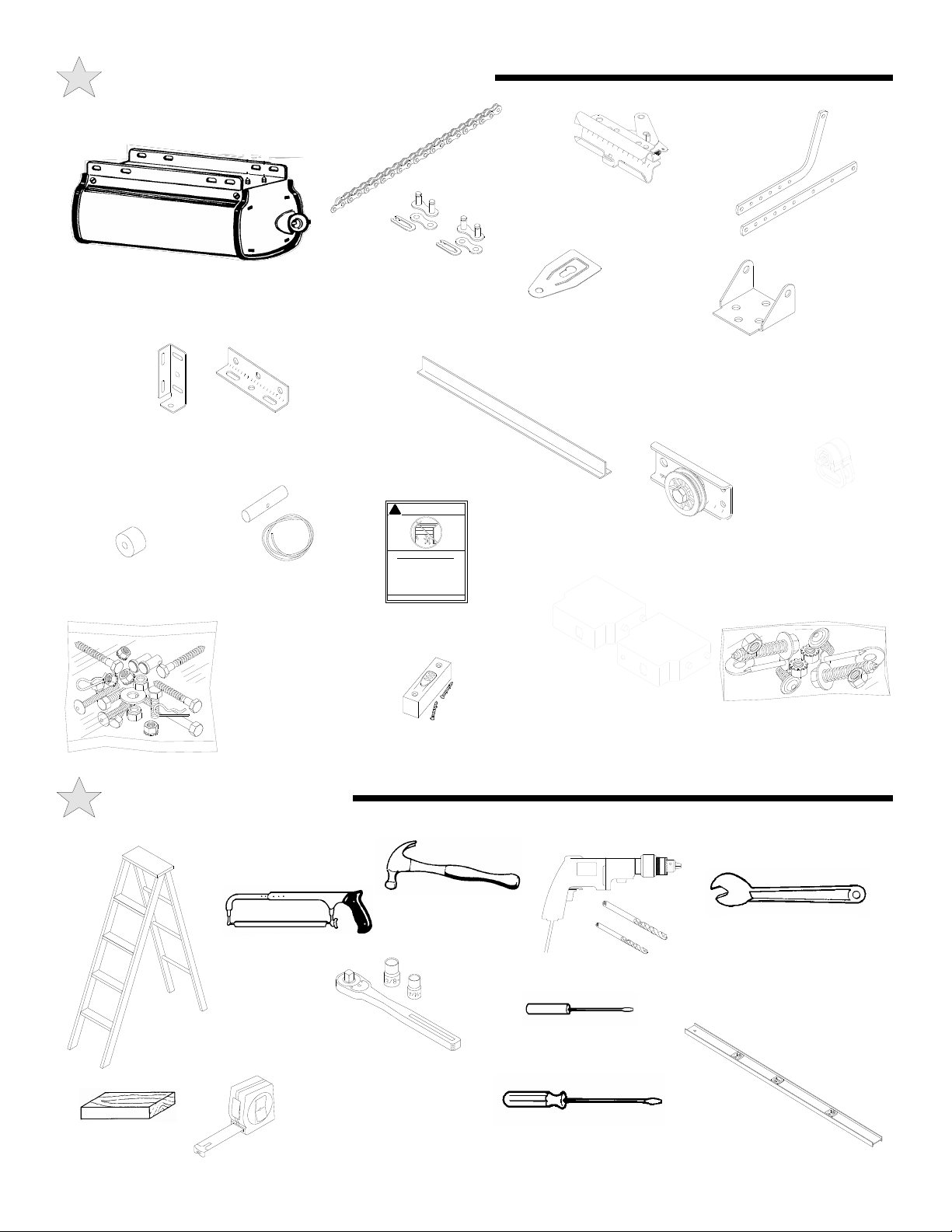
COMPONENT IDENTIFICATION
OPENER HEAD UNIT
ONE-PIECE
DOORS
DOOR MOUNTING
BRACKETS
RUBBER BUMPER
SECTIONAL
DOORS
RELEASE ROPE
AND HANDLE
DRIVE
CHAIN
MASTER
LINKS
TEE RAIL
WARNING
!
Child can be pinned under automatic gar age
door. Death or serious injury can result.
•
Never let child wa lk or run under mov ing door.
•
Never let child use door opener controls.
•
lways keep moving door in sight.
•
If perso n is pi nned, push c ontro l button o r use
emergency release.
•
Test door opener monthly:
Refer to your owner’s manual
Place one-inch ob
ect (or 2x4 laid flat) on floor.
If door fails to reverse on contact, ad
If o
ust opener.
ener still fails t o reve rse door , repair or replace opener.
PUSHBUTTON
“WARNING” LABEL
TROLLEY
OUTER HALF
CHAIN
GUARD
WALL
MOUNTING
BRACKET
FRONT IDLER
ALL-CLEAR
PHOTOSYSTEM
DOOR ARMS
CHAIN LIMIT
CAM
OPENER
HARDWARE
BAG
TOOLS REQUIRED
HACKSAW
STEPLADDER
WOOD
BLOCK
SOCKET WRENCH
3/8” SOCKET
7/16” SOCKET
TAPE MEASURE
ALL-CLEAR HARDWARE
WALL PUSHBUTTON
DRILL
HAMMER
1/2” OPEN END
WRENCH
DRILL & BITS
SMALL SCREW DRIVER
(1/8” HEAD)
LEVEL
SCREW DRIVER
4
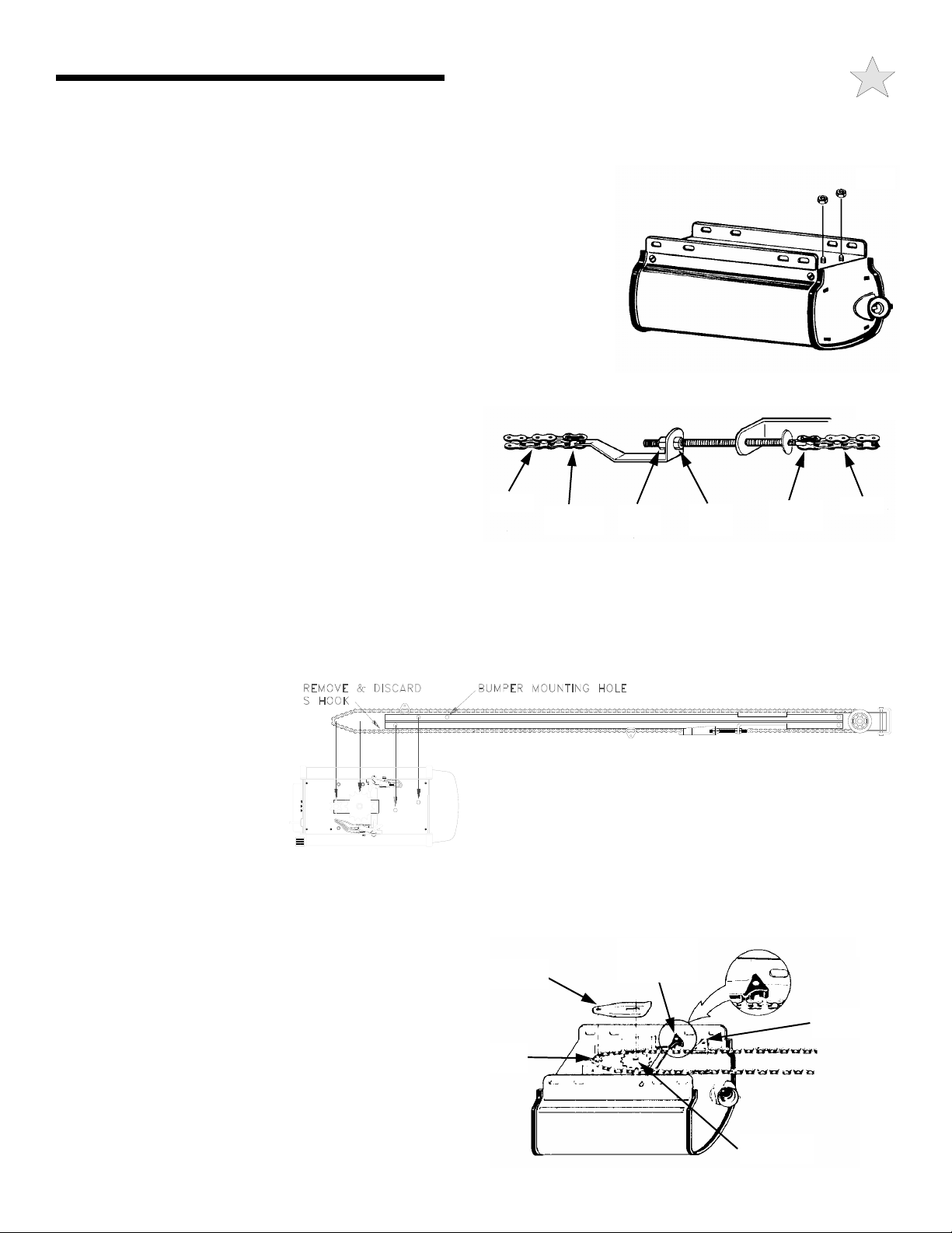
A: ASSEMBLY INSTRUCTIONS
If Your Opener Is Supplied Fully Assembled, Please Disregard This Page.
NOTE: The Tee Rail/Chain Assembly is packaged separately from the Power Unit.
The Inner Trolley half, Front Idler Sprocket, Chain, Restraining Device and Limit Cams
104363
are assembled on the Tee Rail at the factory. Follow the steps outlined below to
complete assembly prior to installation. Refer to the component identification
illustrations on the previous page.
STEP 1: Protect the Power Unit cover from scratching during assembly by placing it on
cardboard. Remove the two 5/16"-18 washered nuts and save them for later use.
STEP 2: Position the Tee Rail/Chain Assembly box near the Power Unit. Open the box
and locate the Installation Hardware Packet.
STEP 3: Locate the Outer Trolley half (packaged with the Power Unit) and slide it onto
the Tee Rail/Chain Assembly with the arrow on the Trolley pointing toward the Door
(Front Idler).
STEP 4: Using a 1/2" wrench, loosen the outer nut on the Chain
104364
Tension Bracket until it is at the end of the threaded rod. Remove
and discard the small "S" hook used to keep the chain tight
during shipping.
STEP 5: Loop the chain around the Idler and Drive Sprocket on
top of the Power Unit and then position the Tee Rail on the studs.
Secure with the two nuts removed in Step 1.
Slightly tension the Chain by tightening the outer nut on the Chain
Tension Bracket. Remove and discard the tape at each end of the Tee Rail Assembly. After double-checking the Chain's alignment
with the Drive Sprocket and Front Idler Wheel, use the inner and outer adjusting nuts on the Chain Tension Bracket to adjust the chain
to the proper tension, making sure the chain does not twist. When correctly adjusted, the Chain should show no droop and be
approximately 1/2" above the base of the Tee Rail.
CHAIN
MASTER
LINK
OUTER
NUT
INNER
NUT
MASTER
LINK
CHAIN
NOTE: If the chain is too loose or too tight, improper operation and/or excessive sprocket noise may result.
STEP 6:
close Limit Switch Actuators to
accept the Limit Cams on the chain,
as shown. Install the Chain Guard
by sliding the key-shaped hole onto
the groove on the Idler Sprocket
Shaft and fully seating the rear hole
over the Drive Sprocket Shaft. The
Limit Cams are installed at the
factory. Their settings should be
considered temporary and may be
changed as required during installation.
Position the open and
104365
STEP 7: Install the Rubber Bumper into its mounting hole on the Tee Rail (see illustration above for location). Secure the Bumper
to the bottom of the Tee Rail using one 5/16"-18 X 1" hex head bolt and one 5/16"-18 washered nut (supplied) Tighten the bolt a
MAXIMUM of 1.5 turns after the bolt and nut are snug.
STEP 8: Recheck the nuts used to secure the Tee Rail to the
Power Unit, making sure they are tight. Recheck the Chain
tension, Chain twist, Chain Guard and the position of both the
Close Limit Switch and Open Limit Switch Actuators.
Assembly is now complete and you are ready to
begin installation of the opener.
CHAIN
GUARD
DRIVE
SPROCKET
CLOSE LIMIT
SWITCH
ACTUATOR
LIMIT CAM
104366
DOWN
IDLER
SPROCKET
5

B: IMPORTANT INSTALLATION
TO REDUCE THE RISK OF SEVERE INJURY
WARNING!
OR DEATH: READ AND FOLLOW ALL
INSTALLATION INSTRUCTIONS!
WARNING: AN UNBALANCED DOOR OR
ONE THAT STICKS OR BINDS MAY
PREVENT THE SENSING SYSTEM FROM
WORKING PROPERLY, CAUSING INJURY OR
DEATH. ENSURE DOOR IS PROPERLY
BALANCED AND ELIMINATE ANY STICKING OR
BINDING PRIOR TO INSTALLATION OF
OPERATOR.
• A properly balanced door will open slowly from a
3/4 open position, close slowly from a 3/4 closed
position, and remain still at a 1/2 open position. If
the door is not properly balanced, HAVE A
QUALIFIED SERVICE PERSON MAKE REPAIRS
TO CABLES, SPRING ASSEMBLIES AND
OTHER DOOR HARDWARE BEFORE
INSTALLING THE OPENER
WARNING: YOUR GARAGE DOOR IS THE
LARGEST MOVING OBJECT IN YOUR
HOUSE, THE SPRINGS, PULLEYS, CABLES
AND MOUNTING HARDWARE UTILIZED TO
BALANCE ITS OPERATION ARE UNDER
EXTREME TENSION AT ALL TIMES AND CAN
CAUSE SERIOUS PERSONAL INJURY, EVEN
DEATH, IF DISTURBED. DO NOT ATTEMPT
ADJUSTMENT.
• CALL A QUALIFIED SERVICE PERSON TO
MOVE, LOOSEN OR ADJUST DOOR SPRINGS
OR HARDWARE.
• REMOVE ALL ROPES AND REMOVE OR
MAKE INOPERATIVE ALL LOCKS CONNECTED
TO THE GARAGE DOOR BEFORE INSTALLING
THE OPENER.
• DO NOT WEAR RINGS, WATCHES OR LOOSE
CLOTHING WHILE INSTALLING OR
SERVICING GARAGE DOOR OPENERS.
WEAR SAFETY GOGGLES OR OTHER
PROTECTIVE EYEWEAR.
• IF POSSIBLE, INSTALL THE DOOR OPENER
7zFT OR MORE ABOVE THE FLOOR. MOUNT
THE EMERGENCY RELEASE 6 FT ABOVE THE
FLOOR.
• REINFORCE LIGHTWEIGHT FIBERGLASS,
ALUMINUM AND STEEL DOOR TOP SECTIONS
TO AVOID DAMAGE AND TO INSURE PROPER
OPERATION OF THE SAFETY REVERSE
SYSTEM. CONTACT YOUR DOOR
MANUFACTURER FOR A REINFORCEMENT
KIT.
• DO NOT CONNECT THE OPENER TO A
POWER SOURCE UNTIL INSTRUCTED TO DO
SO.
• CHECK LOCAL BUILDING AND ELECTRICAL
CODES FOR MANDATORY INSTALLATION
AND WIRING REQUIREMENTS.
• CONNECT POWER CORD ONLY TO A
PROPERLY GROUNDED OUTLET. IF
PERMANENT WIRING IS REQUIRED BY
CODES, DISCONNECT POWER AT FUSE BOX
OR CIRCUIT BREAKER BEFORE ATTEMPTING
ANY WIRING CONNECTIONS.
• LOCATE THE CONTROL PUSH BUTTON:
A. WITHIN SIGHT OF THE DOOR, AND,
B. AT A MINIMUM HEIGHT OF 5 FT SO SMALL
CHILDREN CAN'T REACH IT, AND,
C. AWAY FROM MOVING PARTS OF THE
DOOR.
• INSTALL THE ENTRAPMENT WARNING LABEL
NEXT TO THE CONTROL PUSH BUTTON IN A
PROMINENT LOCATION. INSTALL THE
EMERGENCY RELEASE INSTRUCTION CARD,
ATTACHING IT ON OR NEXT TO THE
EMERGENCY RELEASE.
• ADJUST THE SENSITIVITY ADJUSTMENTS
ENOUGH TO ALLOW THE DOOR TO
OPERATE, BUT NOT SO FIRMLY AS TO EXERT
EXCESSIVE PRESSURE ON AN
OBSTRUCTION BEFORE REVERSING.
• AFTER INSTALLING THE OPENER, THE DOOR
SHOULD REVERSE WHEN IT CONTACTS A
1-1/2" HIGH OBJECT (A PIECE OF STANDARD
2 X 4 BOARD LAID FLAT) ON THE FLOOR.
6
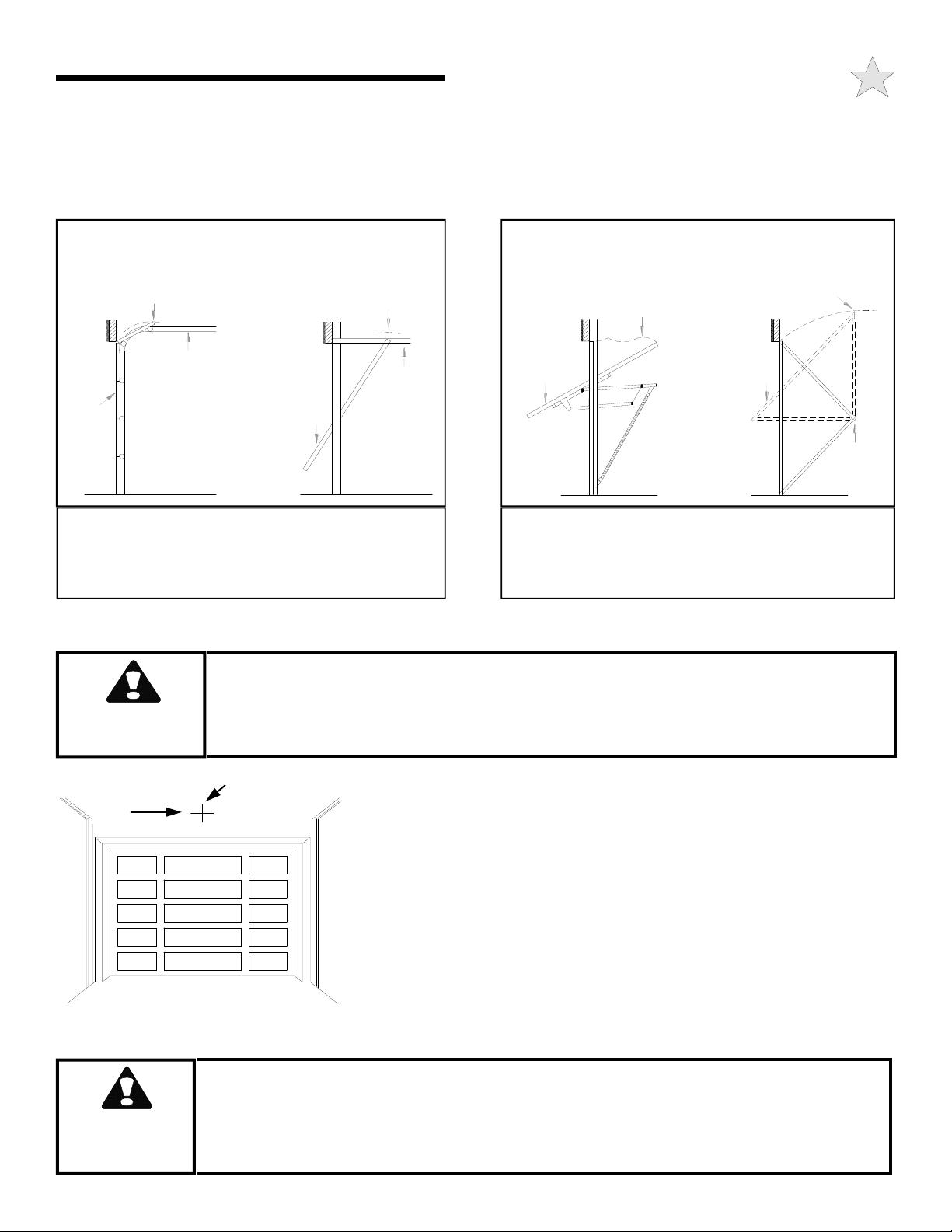
C: INSTALLING THE OPERATOR
IMPORTANT!
IDENTIFY YOUR DOOR TYPE FROM THOSE ILLUSTRATED BELOW AND FOLLOW
INSTRUCTIONS FOR THAT TYPE OF DOOR
104367
SECTIONAL DOOR
CURVED TRACK
HIGH ARC OF
DOOR TRAVEL
TRACK
DOOR DOOR
FOR THESE TYPES OF DOORS USE 1/3 HP
MODEL 3000 OR 1/2 HP MODEL 3500 OR 3500-P.
USE 7 FT, 8 FT OR 10 FT RAIL
(MATCH DOOR HEIGHT)
ONE PIECE DOOR
HORIZONTAL TRACK
JAMB HARDWARE
HIGH ARC OF
DOOR TRAVEL
TRACK
104368
ONE PIECE DOOR
NO TRACK
JAMB HARDWARE
HIGH ARC OF
DOOR TRAVEL
DOOR
JAMB
HARD-
WARE
FOR THESE TYPES OF DOORS USE 1/3 HP MODEL
J3000 OR 1/2 HP MODEL J3500.
USE 7J RAIL
(FOR DOOR HEIGHT UP TO 8 FT)
ONE PIECE DOOR
NO TRACK
PIVOT HARDWARE
HIGH ARC OF
DOOR TRAVEL
DOOR
PIVOT
WARNING
HORIZONTAL
LINE
104369
WARNING
SPRINGS, PULLEYS, CABLES AND MOUNTING HARDWARE USED TO
BALANCE YOUR GARAGE DOOR ARE UNDER EXTREME TENSION AT ALL
TIMES AND CAN CAUSE SEVERE INJURY OR DEATH IF DISTURBED.
DO NOT ATTEMPT ADJUSTMENT.
VERTICAL
CENTERLINE
FRONT MOUNTING BRACKET MUST BE INSTALLED TO A STRUCTURAL SUPPORT
(STUD) ON THE HEADER WALL. FAILURE TO DO SO COULD CAUSE SENSING
SYSTEM TO MALFUNCTION, RESULTING IN ENTRAPMENT, INJURY OR DEATH.
REINFORCE HEADER IF NECESSARY USING A 2 x 6 AND LAG SCREWS
STEP 1: Mounting the Front Bracket — Sectional Doors and One-
Piece Doors with Track (For One-Piece Doors without track see Step 1A,
next): Mark a vertical centerline on the header above the door. By
manually raising the door, determine the high arc of the door’s travel (see
illustration, above left) and using a level, transfer this measurement to the
header (see illustration at left). Draw a horizontal line, crossing the
previously drawn centerline, at this point. Install the Front Mounting
Bracket securely wit lag screws as shown on the following page. If
necessary, reinforce the header with steel angle iron or wood to ensure a
secure mount.
(NOT PROVIDED).
7
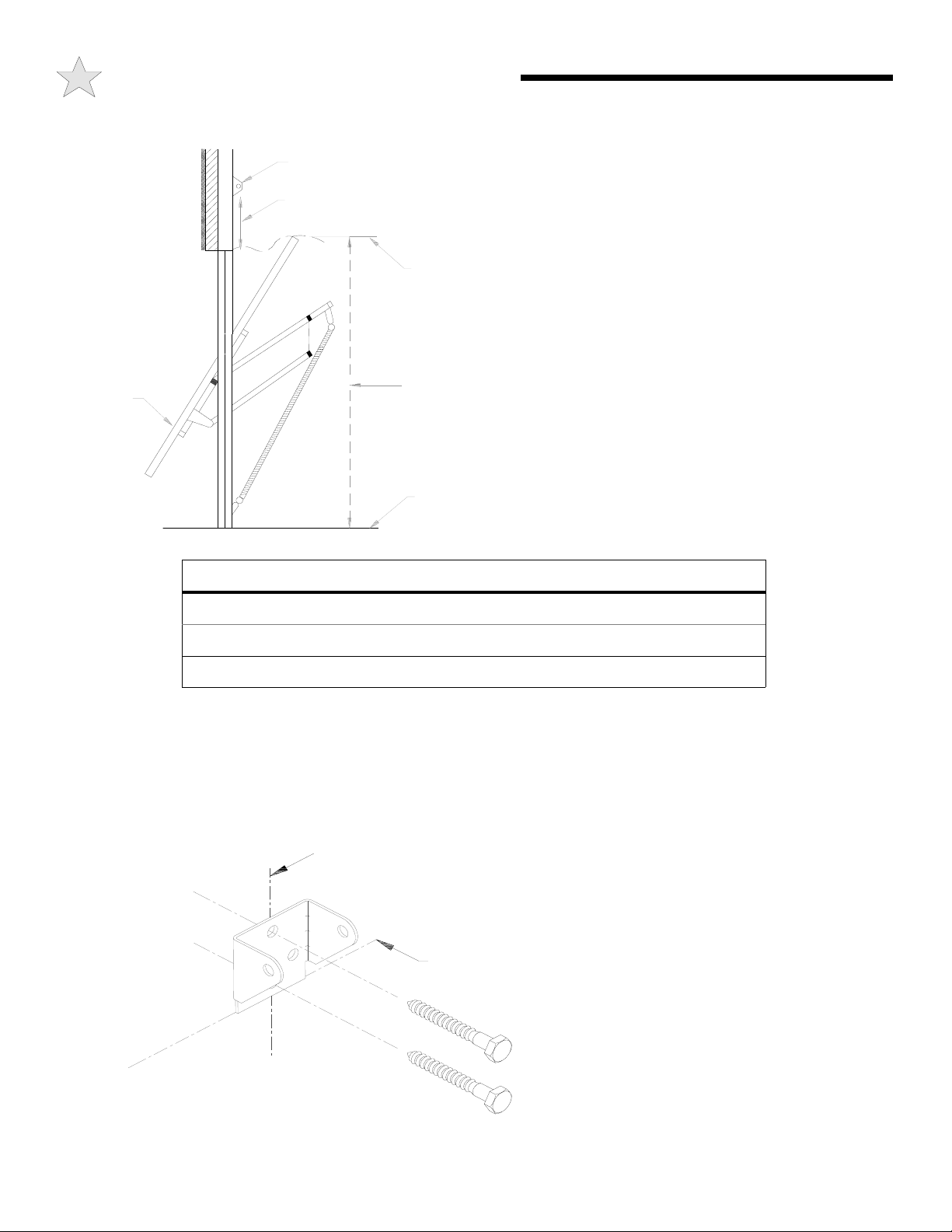
C: INSTALLING THE OPERATOR
104370
Door
Header Bracket
STEP 1A: Mounting the Front Bracket — One
Piece Doors Without Track: Mark a vertical
centerline on the header above the door. Manually raise
Bracket Distance Above Floor
(See Chart)
the door to its high arc position and temporarily clamp
in that position. With the door in this high arc position,
measure the distance from the top of the door to the
floor (see figure at left). Subtract the actual door height
Highest Point
of Travel
from the high arc distance to the floor. This is the high
arc rise of the door. Unclamp and close the door.
Using the table below, draw a horizontal line at the
appropriate height above the door to intersect with the
vertical centerline.
Measure
Distance
to Floor
Garage
Floor
HIGH ARC RISE HIGH ARC RISE HORIZONTAL LINE
104371
4 INCHES 6 INCHES
4 TO 8 INCHES 11 INCHES
8 TO 12 INCHES 16 INCHES
Mount the Front Mounting Bracket securely with lag
screws as shown in figure below. If necessary,
reinforce the header with steel angle iron or wood to
ensure a secure mount.
VERTICAL
CENTERLINE
HIGH ARC (RISE)
HORIZONTAL LINE
LAG SCREWS
5/16” X 1-7/8”
8
 Loading...