

Page 1

INSTALLER: Place this manual in the plastic envelope provided and permanently
attach to the wall near the pushbutton.
INSTALLATION AND
OWNER’S MANUAL
ALLSTAR LT 50
Commercial Vehicular Garage Door Operator
Model Number LT 50 for 10 FT and 12 FT High
Sectional Doors and One Piece Doors with Track.
110060
110044
BY
As of date of manufacture,
meets all ANSI/UL 325
Safety Requirements for
Vehicular Garage Door
Operators
Serial #:
Date Installed:
Your Dealer:
READ THIS MANUAL
CAREFULLY BEFORE
INSTALLATION OR USE
1
Page 2
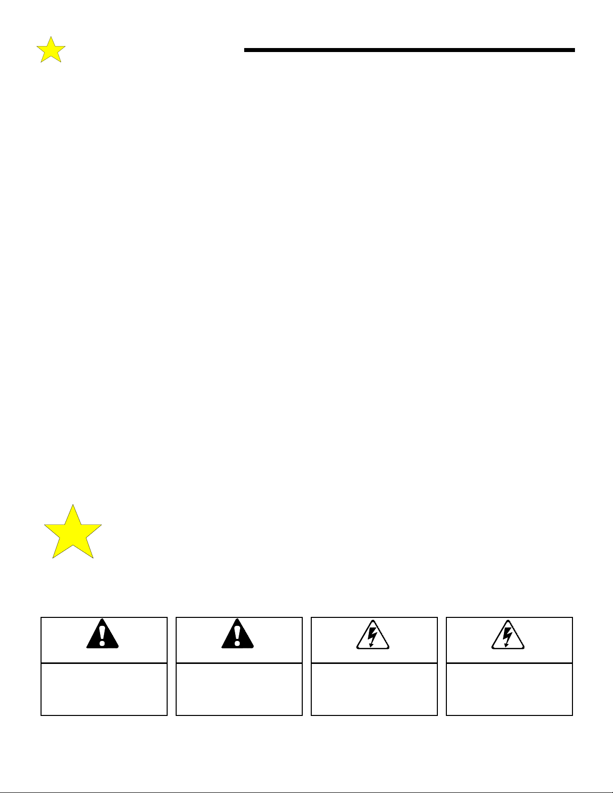
TABLE OF CONTENTS
Product Features ............................................................ 3
Component Identification/Tools Required...................4
Section A: Assembly Instructions................................ 5
Section B: Installation Notes........................................6
Section C: Installing the Operator ...............................7
Identify Your Door Type ..........................................7
Mounting the Front Bracket .................................... 8
Mounting the Power Head.......................................9
Door Bracket Installation......................................... 9
Pushbutton Connection ........................................ 10
Optional Safe Finish Photoelectric
Installation ..............................................................11
Configuring the Motor Control Board
for External Devices............................................... 12
Initial Test of Safe Finish Photosystem ............... 12
Connecting the Door Arm .....................................13
Testing the Sensitivity ...........................................14
Section D: Auxiliary Equipment ................................15
Installation of Radio Controls..............................15
Section E: Adjustments..............................................16
Open Travel Adjustment ...................................... 16
Open & Close Obstruction Force........................16
Obstruction Sensitivity at Close Position .......... 16
Positive Mechanical Lock Adjustment ............... 17
Travel Time Adjustment.......................................17
Important Safety Instructions ................................... 17
Section F: Operating Instructions ............................ 18
How To Activate The Opener............................... 18
Sequence of Operation ........................................18
How the Light Works ...........................................18
How To Operate The Door Manually...................19
Safe Finish Wiring Diagrams .....................................20
Optional Pneumatic Door Edge Installation ............. 20
Maintenance Schedule ...............................................21
Installation Checklist .................................................. 21
Troubleshooting Guide .............................................. 22
Parts Breakdown and Listing..................................... 23
Warranty Information .................................................24
READ THESE STATEMENTS CAREFULLY AND FOLLOW THE
The Warning and Caution boxes throughout this manual are there to protect you and
your equipment. Pay close attention to these boxes as you follow the manual.
WARNING
Indicates a MECHANICAL
hazard of INJURY OR
DEATH. Gives instructions
to avoid the hazard.
INSTRUCTIONS CLOSELY.
CAUTION
Indicates a MECHANICAL hazard
of DAMAGE to your door, door
operator, or equipment. Gives
instructions to avoid the hazard.
WARNING
Indicates an ELECTRICAL
hazard of INJURY OR
DEATH. Gives instructions
to avoid the hazard.
2
CAUTION
Indicates an ELECTRICAL hazard
of DAMAGE to your door, door
operator, or equipment. Gives
instructions to avoid the hazard.
Page 3

PRODUCT FEATURES
The purpose of this booklet is to provide assembly,
installation and operation information concerning the Allstar
LT 50 Commercial Vehicular Garage Door Openers and related
Accessory Products.
NOTICE
IT IS IMPORTANT THAT THIS INSTRUCTION
MANUAL BE READ AND UNDERSTOOD
COMPLETELY BEFORE INSTALLATION OR
OPERATION IS ATTEMPTED.
NOTICE
THE IMPORTANT SAFEGUARDS AND
INSTRUCTIONS IN THIS MANUAL CANNOT
COVER ALL POSSIBLE CONDITIONS AND
SITUATIONS WHICH MAY OCCUR DURING ITS
USE. IT MUST BE UNDERSTOOD THAT
COMMON SENSE AND CAUTION MUST BE
EXERCISED BY THE PERSON(S) INSTALLING,
MAINTAINING AND OPERATING THE
EQUIPMENT DESCRIBED HEREIN. DO NOT
USE THIS EQUIPMENT FOR ANY OTHER THAN
ITS INTENDED PURPOSE - OPERATING
OVERHEAD GARAGE DOORS.
The Model LT 50 drawbar operators are used in the following
applications:
-Restricted Duty, Limited Cycle Commercial installations only.
-Rate of operation shall not exceed 6 cycles of openings and
closings per hour, maximum of 40 cycles per day.
-Indoor Use Only.
-Up to 12 foot high doors with a maximum weight of 400
pounds.
-Use with Safe Finish™ Photosystem (light beam across the
door opening) or foam/pneumatic reversing edge door
components - REQUIRED where the push button is out of sight
of the door or any other automatic, remote or manual control is
used to activate the door.
Alternating Action Operation: The mechanical wall
pushbutton functions in an Open/Stop/Close/Stop mode
in normal operation. (Page 18)
Manual Release: A pull cord allows separation of the
drive mechanism and manual operation of the door when
desired, as in the event of a power failure. (Page 19)
Automatic Reconnection: Once power is restored,
or automatic operation of the door is again desired,
initiating operation in the normal manner (Push Button,
Radio Control, etc.) will effect automatic reconnection of
the Manual Release Mechanism. (Page 19)
Connections For Continuously Monitored
Auxiliary Entrapment Protection Devices:
LT 50 Safe Finish™ Photosystem (light beam across the
door opening) can be easily connected to the Opener.
Control circuitry monitors the device continuously for
proper operation. (Page 11) Consult the factory for
compatibility of other auxiliary entrapment protection
devices.
The
Momentary Contact To Close: The standard close
operation mode is momentary contact of the mechanical
Push Button, and a portable Radio Transmitter can be
used to close the door (PageZ18). The internal Sensing
System (described earlier) detects obstructions in the
door’s path.
Constant Contact To Close: For utmost safety, after
installation of a Safe Finish™ Photosystem, the standard
operation mode can be configured to require constant
contact on the mechanical Push Button to close the door
if the photosystem fails or if there is a break or short in
the wiring. In this mode of operation, a Radio
Transmitter cannot be used to close the door. (Page 18)
Safe Finish™ Photosystem: An invisible infrared
beam of light guards the door opening and reverses a
downward moving door if the beam is broken by a
stationary or moving object. The LT 50 motor control
circuitry can be configured to constantly monitor the Safe
Finish Photosystem for proper operation.
STANDARD FEATURES:
Sensing System: A built-in sensing system detects
obstructions during door operation. If in the downward (close)
travel mode, the Opener will sense an obstruction and reverse
the direction of the door. In the open mode, the Opener will
stop. Since all doors are different, the Sensing System has
independent adjustments for customizing the level of force
required for the normal opening and closing of specified doors.
( Page 16)
Close Limit Switch: In winter months it's common for small
pieces of ice or packed snow to be trapped under the door.
Ground swelling can also effect the close limit setting of the
Opener. The LT 50 Close Limit Switch overrides the Sensing
System during the last one inch of closing travel and prevents
the door from reversing if it encounters an obstruction at this
point.
3
OPTIONAL FEATURES:
Digital Radio Controls: The LT 50 Opener covered
in this Manual can be fitted with optional Radio Controls.
Up to 19,683 private codes can be easily selected without
use of tools. (PageZ15)
Deluxe Wall Push Button: A feature-packed
accessory unit, the Deluxe Wall Station allows access to
all of the Opener's functions. Open/Close button permits
full control of the door’s operation. The Opener's
built-in light can be turned on or off independent of door
operation. A Security Switch allows the Opener to be
deactivated for extended periods of time. (Page 19)
Keyless Entry System: A tamper resistant outdoor
keypad, the optional Keyless Entry System permits entry
to the garage without use of key or radio transmitter.
Easily programmable, it accommodates four separate
access codes of 4 digits. Lighted Buttons enhance
nighttime use.
Page 4
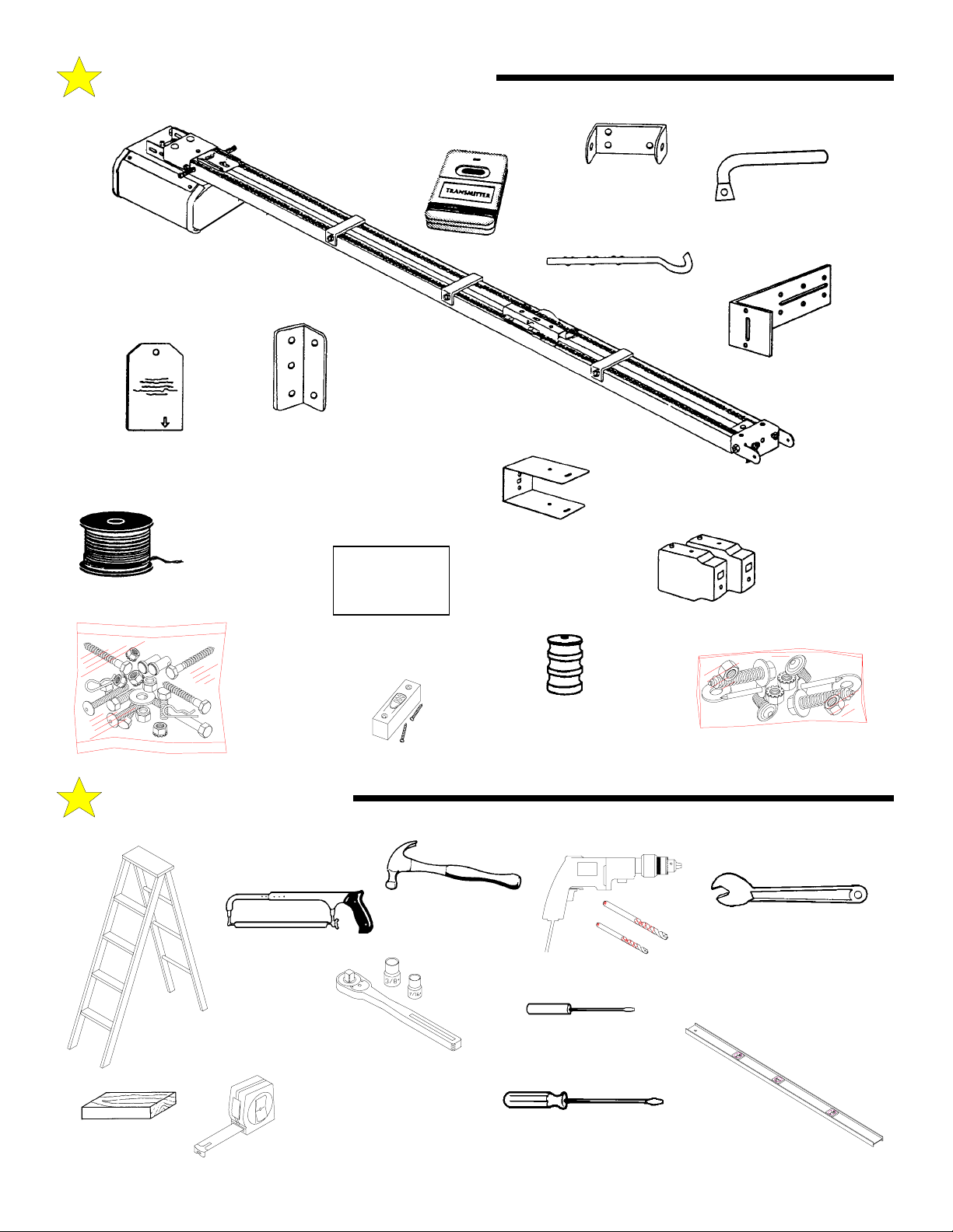
COMPONENT IDENTIFICATION
TRANSMITTER
OPTIONAL
POWER HEAD/DRIVE
RAIL ASSEMBLY
WALL
BRACKET
DOOR ARM ROD
DOOR ARM
TUBE SECTION
SENSOR ‘L’
BRACKET
(OPTIONAL)
MANUAL RELEASE
TAG
BELL WIRE
SPOOL
(when supplied)
110045
OPENER
HARDWARE
TOOLS REQUIRED
DOOR
BRACKET
BAG
This door is operated by
a limited duty operator.
To prevent the motor
protector from tri pping Do not exceed 6 door
cycles per hour.
PUSHBUTTON
“WARNING” LABEL
WALL PUSHBUTTON
SENSOR ‘U’
BRACKET
(OPTIONAL)
RED
RELEASE
KNOB
SAFE FINISH
PHOTOSYSTEM
SENSORS
(OPTIONAL)
110046
SAFE FINISH HARDWARE
(OPTIONAL)
STEPLADDER
WOOD
BLOCK
HACKSAW
SOCKET WRENCH
3/8” SOCKET
7/16” SOCKET
TAPE MEASURE
HAMMER
1/2” OPEN END
WRENCH
DRILL & BITS
SMALL SCREW DRIVER
(1/8” HEAD)
LEVEL
SCREW DRIVER
4
Page 5
A: ASSEMBLY INSTRUCTIONS
If Your Opener Is Supplied Fully Assembled, Please Disregard This Page.
NOTE: The Rail/Chain Assembly is
packaged separately from the Power
Head Unit. The trolley, front idler/
tension adjustment assembly, chain,
drive gear and limit cams are assembled
to the Rail/Chain Assembly at the
factory. Follow the steps outlined
below to complete assembly prior to
installation. Refer to the component
identification illustrations on the
previous page.
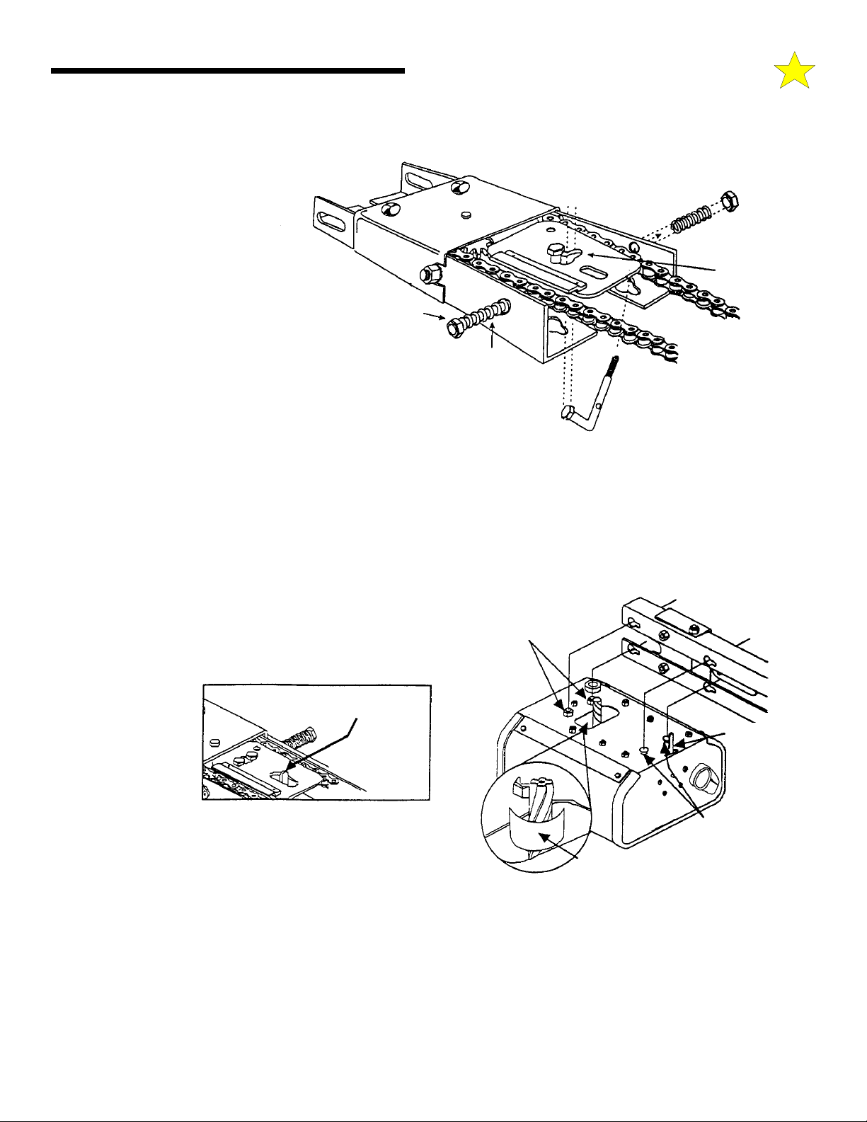
STEP 1: Prior to attaching the motor
drive unit to the rail assembly, the Open
and Close adjustment bolts must be
installed. Place the threaded end of the
adjustment bolt through the hole in the
rail and then slip the head of the bolt
through the center of the double key
hole. Slide the spring over the bolt and attach load adjusting nut. Tighten until the tip of the bolt extends 3/16” outside the nut. Repeat
above for the other side.
Assembled and
In Position
Spring
Spring
L-Shaped Adjustment Bolt
Force Adjusting
Plastic-Insert
Locking Nut
Double Key Hole
110047-1
STEP 2: Protect the Power Unit cover from scratching during assembly by placing it on cardboard. Loosen the two 5/16" lock washer
nuts on top of the power head drive unit.
STEP 3: VERY IMPORTANT ! Position a paper shim around the power head unit drive gear (standard weight paper, see
illustration). Shim must remain in place while assembling the power head unit to the Rail/Chain assembly to ensure a proper gear mesh
and avoid excessive long term wear.
STEP 4: Align the four key holes in the Rail/Chain assembly with
the two front guide tabs and the two rear bolt studs on the power head
unit and place the rail/chain assembly in place over the power head
unit. The power head drive unit limit lever protrudes up through the
rail/chain assembly sensing plate. Take care not to bend the lever
when assembling. Slide
the power head drive
unit forward until the
gear meshes with the
rail/chain assembly
drive gear. Check to
make sure the front
guide tabs on the power
head unit are securely
locked on the rail/chain
assembly.
110047-2
Take care not to
bend limit lever
Limit Lever
5/16” Lock
Washer Nuts
Limit
Lever
Front Guide
Tabs (2)
Paper Shim
110047-3
STEP 5: The power head drive unit should be move forward until all play between the gears has been eliminated, but no additional
force should be used that could cause pressure on the motor (power head unit) drive gear. Tighten the two 5/16" lock washer nuts on
top of the power head drive unit that were loosened in Step 2 above.
When the opener is first activated the paper shim will be ejected. The paper shim should have the profile of the gears to indicate the
proper mesh between them.
STEP 6: Recheck the nuts used to secure the Rail/Chain assembly to the Power Head Unit, making sure they are tight.
Assembly is now complete and you are ready to begin installation of the opener.
5
Page 6
B: IMPORTANT INSTALLATION NOTES
TO REDUCE THE RISK OF SEVERE INJURY
WARNING!
OR DEATH: READ AND FOLLOW ALL
INSTALLATION INSTRUCTIONS!
WARNING : AN UNBALANCED DOOR OR
ONE THAT STICKS OR BINDS MAY
PREVENT THE SENSING SYSTEM FROM
WORKING PROPERLY, CAUSING INJURY OR
DEATH. ENSURE DOOR IS PROPERLY
BALANCED AND ELIMINATE ANY STICKING OR
BINDING PRIOR TO INSTALLATION OF
OPERATOR.
• A PROPERLY BALANCED DOOR WILL OPEN
SLOWLY FROM A 3/4 OPEN POSITION, CLOSE
SLOWLY FROM A 3/4 CLOSED POSITION, AND
REMAIN STILL AT A 1/2 OPEN POSITION. IF
THE DOOR IS NOT PROPERLY BALANCED,
HAVE A QUALIFIED SERVICE PERSON MAKE
REPAIRS TO CABLES, SPRING ASSEMBLIES
AND OTHER DOOR HARDWARE BEFORE
INSTALLING THE OPENER
WARNING:
LARGE MOVING OBJECT (SIMILAR TO MOVING
A WALL). THE SPRINGS, PULLEYS, CABLES
AND MOUNTING HARDWARE UTILIZED TO
BALANCE ITS OPERATION ARE UNDER
EXTREME TENSION AT ALL TIMES AND CAN
CAUSE SERIOUS PERSONAL INJURY, EVEN
DEATH, IF DISTURBED. DO NOT ATTEMPT
ADJUSTM ENT.
• CALL A QUALIFIED SERVICE PERSON TO
MOVE, LOOSEN OR ADJUST DOOR SPRINGS
OR HARDWARE.
• REMOVE ALL ROPES AND REMOVE OR MAKE
INOPERATIVE ALL LOCKS CONNECTED TO
THE GARAGE DOOR BEFORE INSTALLING
THE OPENER.
• DO NOT WEAR RINGS, WATCHES OR LOOSE
CLOTHING WHILE INSTALLING OR SERVICING
GARAGE DOOR OPENERS. WEAR SAFETY
GOGGLES OR OTHER PROTECTIVE
EYEWEAR.
• INSTALL THE DOOR OPENER 8zFT OR MORE
ABOVE THE FLOOR. MOUNT THE MANUAL
RELEASE 6 FT ABOVE THE FLOOR.
YOUR GARAGE DOOR IS A
• REINFORCE LIGHTWEIGHT FIBERGLASS,
ALUMINUM AND STEEL DOOR TOP SECTIONS
TO AVOID DAMAGE AND TO INSURE PROPER
OPERATION OF THE SAFETY REVERSE
SYSTEM. CONTACT YOUR DOOR
MANUFACTURER FOR A REINFORCEMENT
KIT.
• DO NOT CONNECT THE OPENER TO A
POWER SOURCE UNTIL INSTRUCTED TO DO
SO.
• CHECK LOCAL BUILDING AND ELECTRICAL
CODES FOR MANDATORY INSTALLATION AND
WIRING REQUIREMENTS.
• DISCONNECT POWER AT FUSE BOX OR
CIRCUIT BREAKER BEFORE ATTEMPTING
ANY PERMANENT WIRING CONNECTIONS.
FOLLOW ALL LOCAL, STATE AND FEDERAL
MANDATED ELECTRICAL CODES.
• LOCATE THE CONTROL PUSH BUTTON:
A. WITHIN SIGHT OF THE DOOR, AND,
B. AT A MINIMUM HEIGHT OF 5 FT TO
DISCOURAGE UNAUTHORIZED OPERATION,
AND,
C. AWAY FROM MOVING PARTS OF THE
DOOR.
• INSTALL THE PUSH BUTTON WARNING LABEL
(“This door is operated by a limited ...”) NEXT TO
THE CONTROL PUSH BUTTON IN A
PROMINENT LOCATION. INSTALL THE
MANUAL RELEASE INSTRUCTION CARD,
ATTACHING IT ON OR NEXT TO THE MANUAL
RELEASE MECHANISM.
• ADJUST THE SENSITIVITY ADJUSTMENTS
ENOUGH TO ALLOW THE DOOR TO OPERATE,
BUT NOT SO FIRMLY AS TO EXERT
EXCESSIVE PRESSURE ON AN OBSTRUCTION
BEFORE REVERSING.
• AFTER INSTALLING THE OPENER, THE DOOR
SHOULD REVERSE WHEN IT CONTACTS A
1-1/2" HIGH OBJECT (A PIECE OF STANDARD
2 X 4 BOARD LAID FLAT) ON THE FLOOR.
6
Page 7
C: INSTALLING THE OPERATOR
IMPORTANT!
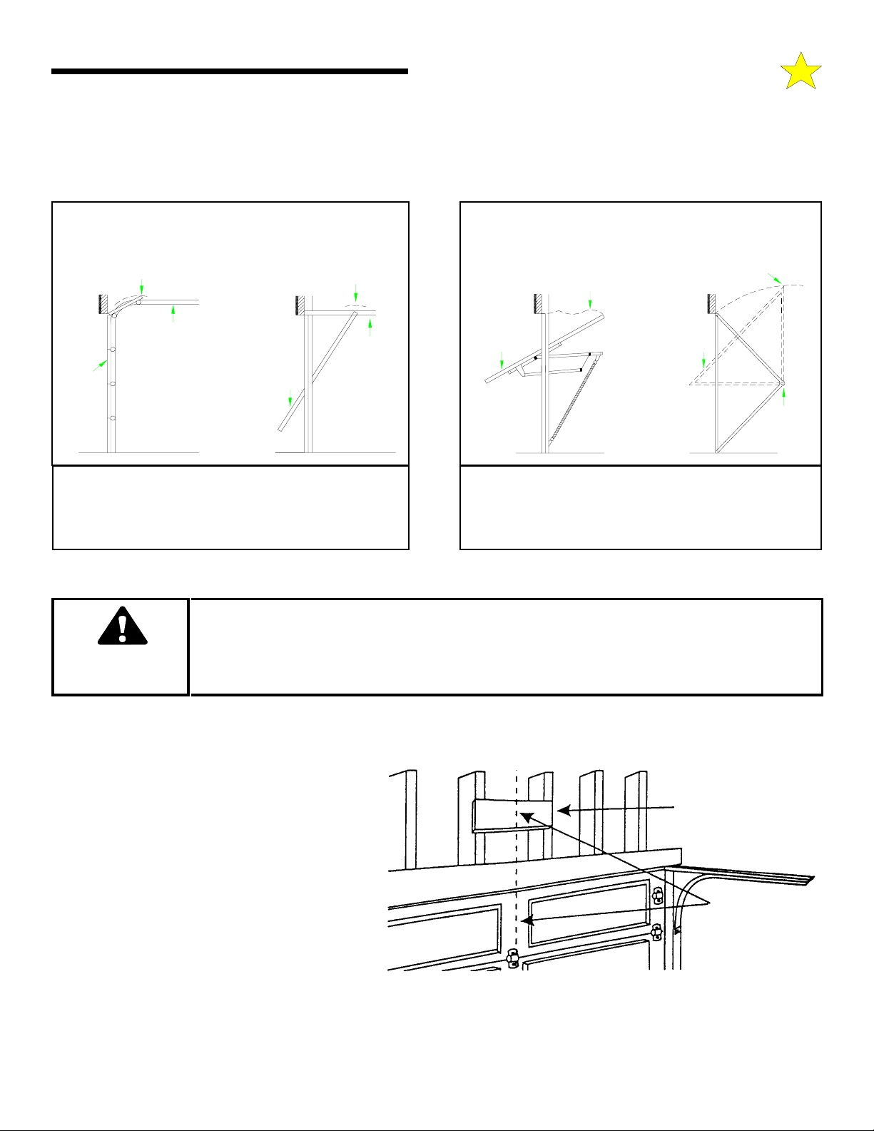
IDENTIFY YOUR DOOR TYPE FROM THOSE ILLUSTRATED BELOW.
104367
SECTIONAL DOOR
CURVED TRACK
ONE PIECE DOOR
HORIZONTAL TRACK
JAMB HARDWARE
HIGH ARC OF
DOOR TRAVEL
TRACK
DOOR DOOR
FOR THESE TYPES OF DOORS USE 1/2 HP
MODEL LT 50.
USE 10 FT OR 12 FT RAIL ASSEMBLY
(MATCH DOOR HEIGHT)
HIGH ARC OF
DOOR TRAVEL
TRACK
104368
ONE PIECE DOOR
NO TRACK
JAMB HARDWARE
HIGH ARC OF
DOOR TRAVEL
DOOR
JAMB
HARD-
WARE
ONE PIECE DOOR
NO TRACK
PIVOT HARDWARE
HIGH ARC OF
DOOR TRAVEL
DOOR
PIVOT
NOTE:
THE MODEL LT 50 CANNOT BE USED TO OPERATE
THESE TYPES OF DOORS - CONTACT THE
FACTORY FOR MORE INFORMATION.
SPRINGS, PULLEYS, CABLES AND MOUNTING HARDWARE USED TO
BALANCE YOUR GARAGE DOOR ARE UNDER EXTREME TENSION AT ALL
TIMES AND CAN CAUSE SEVERE INJURY OR DEATH IF DISTURBED.
WARNING
REINFORCE THE HEADER WALL
Reinforce the header wall (wall above the door
opening as required, to ensure rigid mounting of the
front wall bracket.
Locate the vertical centerline of your garage door
and mark it on the header above the door and on the
top rail of the door.
DO NOT ATTEMPT ADJUSTMENT.
Reinforce with 2” x 6”
as required to insure
rigid mounting.
Vertical Center
Line
110048
7
Page 8
C: INSTALLING THE OPERATOR
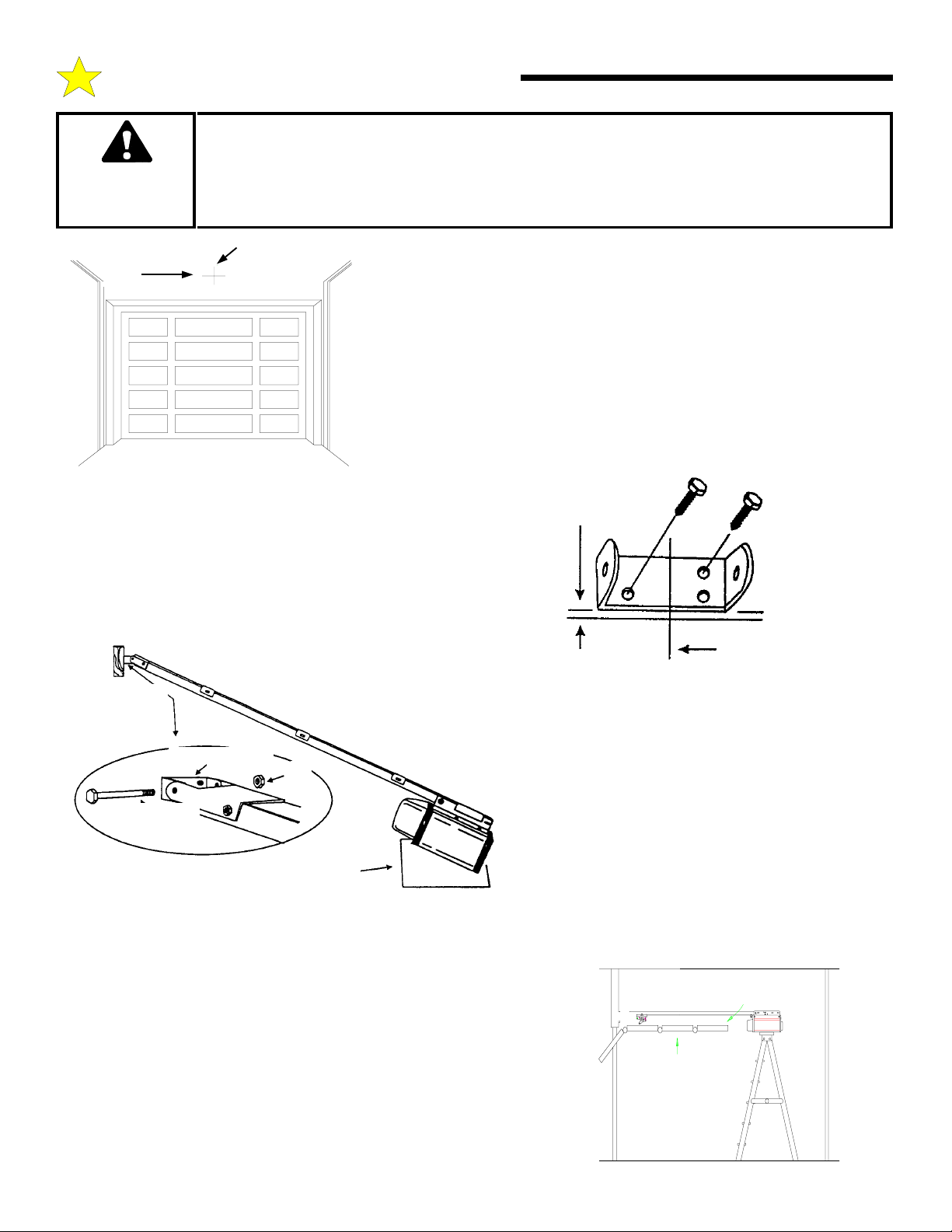
FRONT MOUNTING BRACKET MUST BE INSTALLED TO A STRUCTURAL SUPPORT
(STUD) ON THE HEADER WALL. FAILURE TO DO SO COULD CAUSE SENSING
SYSTEM TO MALFUNCTION, RESULTING IN ENTRAPMENT, INJURY OR DEATH.
WARNING
REINFORCE HEADER USING 2 x 6 WOOD STUDS AND LAG SCREW OR ANGLE
IRON AND LAG SCREWS AS NECESSARY (NOT PROVIDED).
HORIZONTAL
LINE
VERTICAL
CENTERLINE
STEP 1: Mounting the Front Bracket: Mark a vertical centerline on the
header above the door. By manually raising the door, determine the high arc
of the door’s travel (see illustration, top of previous page) and using a level,
transfer this measurement to the header (see illustration at left). Draw a
horizontal line, crossing the previously drawn centerline, at this point. Install
the Front Mounting Bracket securely wit lag screws as shown below. If
necessary, reinforce the header with steel angle iron or wood to ensure a
secure mount.
104369
Mount the Front Mounting Bracket securely with lag screws as
shown in figure at right. If necessary, reinforce the header with
steel angle iron or wood to ensure a secure mount.
STEP 2: Raise the front of the Rail/Chain assembly so that the
Front Rail Bracket and Wall Mounting Bracket align. Insert the
1/4” x 4” bolt and tighten nut loosely for now. Later in the
installation, this nut must be tightened securely.
Wall
Mounting
Bracket
Wall Mounting Bracket
Nut
1/4” x 4”
Hex Head Bolt
110050-1
110049
1/2” Above
High Arc Mark
Front Wall
Bracket
Center of
High Arc Mark
Door
STEP 3 — Raise the Opener and rest the Power Unit
on a ladder or other sturdy support. Open the door the
full open position. Allow 2" of space between the Tee
Rail and the top section of the door (as shown in the
illustration, below on the right).
Cardboard or Cloth to
protect the Housing
NOTE: Since the Opener will be secured permanently in this position,
open and close the door a few times to be sure the door does not rub on
the Tee Rail and that you have allowed the proper clearances before
proceeding.
8
SECTIONAL DOORS AND ONE-PIECE DOORS
WITH TRACK
ALLOW 2” BETWEEN
TOP OF DOOR AND RAIL
DOOR FULLY
OPEN
Page 9

C: INSTALLING THE OPERATOR
STEP 4: Mount Power Head to Ceiling:
110050-2
Since there is such variety in ceiling structures,
all the mounting possibilities for the Power Unit
cannot be illustrated here. The main concern is
mounting the Power Unit securely to the ceiling
joists for operational strength, rigidity and
safety. Although there are a series of mounting
slots provided on the power unit, try to secure
the mounting straps in the slots closest to the
Structural
Beams
Cut and bend
Hangers to fit
front. Mounting may usually be accomplished
using standard 1-1/4“ perforated steel angle
available at most hardware stores. If in doubt
about location of, and attachment to, ceiling
joists, a carpenter should be contacted to
provide assistance. A cross brace will be
necessary if power head is mounted 8” or more
from the ceiling.
Opener
Power Head
For finished ceilings, or if
structural beams are out of
position for mounting use a
third mounting angle (not
included) making sure it is
securely mounted to beams.
Align the center of opener tracks with the center line previously marked on the top section of the garage door to ensure rail will be
parallel with the direction of door travel.
Use supplied hangers from the ceiling beams to hang the opener at the power head end (be sure to locate and mount to the solid
structural beams, as illustrated). Predrill with 3/16” drill bit and use 1/4” lag screws of appropriate length to ensure a rigid mount.
NOTE: Hanging brackets should be at an angle to provide rigid support. If hangers have no angle or if you use longer hangers, cross
brace the hangers to eliminate the possibility of sway during operation of the opener.
STEP 5: Return to the Rail/Wall Mounting Bracket and securely tighten the bolt and nut that connect the Rail Front Idler
bracket and the Wall Mounting Bracket. Take care not to over tighten the nut; tighten only until the end of the bolt is secured to the
bracket (See Step 2, above).
Fiberglass, aluminum or lightweight steel
STEP 6: Door Bracket Installation
If your door comes equipped with a strut
mounted opener bracket, follow the door
manufacturer’s instructions to install the bracket
to the door then proceed to Step 7.
NOTE: If the door is of light construction it will be necessary
to reinforce the center stile with steel angle or wood to prevent
damage to the door if it encounters an obstruction on closing.
Mount the door bracket using two 1/4”-20 x 2” carriage bolts
and 1/4” nuts (supplied), on center line of door with the
middle hole in line with the top rollers.
WARNING
110051-1
garage doors will require
installation of the door mounting bracket
Contact your door manufacturer for a
reinforcement kit or instructions.
Door Center Line
reinforcement before
Top Roller
Guideline
Reinforce Door
Vertically and
Horizontally
Mounting
Bracket
If your door comes equipped with a strut mounted opener
bracket, follow the door manufacturer’s instructions to
install the bracket to the door then proceed to Step 7.
Top Roller
Guideline
110051-2
9
Page 10

C: INSTALLING THE OPERATOR
STEP 7: Install a Rough Service lamp bulb (75 Watt
maximum) firmly in the light socket. Light bulbs in Door Openers are
subject to vibration during normal operation which may shorten their
life spans. Rough Service bulbs, available at most hardware stores,
are recommended.
108385
UNAUTHORIZED OPERATION OF THE DOOR
CONTROLS RISKS INJURY OR DEATH . DO NOT
ALLOW ANYONE UNFAMILIAR WITH THE DOOR
OPERATION TO OPERATE ANY DOOR
WARNING
CONTROLS. MOUNT THE PUSHBUTTON AT
LEAST 5 FT FROM THE FLOOR.
110051-3
STEP 8: Connect the standard wall Push Button
provided to Terminals 1 & 0
panel using a length of 2-conductor, minimum 22 gauge
wire. For mounting the standard Push Button, select a
convenient location near an access door. MOUNT AT
LEAST 5 FT FROM THE FLOOR TO
DISCOURAGE UNAUTHORIZED OPERATION OF
THE DOOR. Install the push button warning label (as
shown below) supplied with the Opener near this
installation.
If you are installing a Deluxe Wall Push Button), See
Page 19 for the proper wiring procedure.
on the Opener's rear
This door is operated by
a limited duty operator.
To prevent the motor
protector from tripping Do not exceed 6 door
cycles per hour.
STEP 9: Connecting The Electrical Power Consult the label on the rear
panel of the Opener to determine its proper working voltage. Normally it will be
marked for 115V, 60 cycle operation. (If it is a 230V model the label will clearly
indicate this.) The Opener
Permanent Wiring Connection
Use an appropriate
conduit connector
Ground Wire &
Chassis Connection
L1 & L2
Connections
110442
must be permanently
wired with a proper
ground connection
according to all
applicable local, state,
and federal building and
electrical codes. Run a
three (3) conductor
(minimum #14, copper
conductors only) wire from a 15 AMP circuit breaker to the operator in a
suitable conduit. Use an appropriate connector to secure the conduit to the
operator chassis as shown. Connect the incoming line and neutral power
wires (L1 and L2) at the terminal block according to the diagram. Secure the
incoming earth ground to the chassis ground screw as shown .
NOTE: GFI protection is recommended especially on steel door applications.
10
WARNING
IMPROPER WIRING COULD
CAUSE ELECTROCUTION
OR DAMAGE TO CIRCUITRY.
FOLLOW LOCAL BUILDING
AND ELECTRICAL CODES.
104350
Page 11

C: INSTALLING THE OPERATOR
OPTIONAL SAFE FINISH PHOTOSYSTEM INSTALLATION
12 Inches From Door Opening
NOTE: Skip to Step 15 on Page 13 if not installing a Safe Finish Photosystem at this
time.
Identify which side of the garage door opening (if any) the sun is “likely” to shine
into. As sunlight may cause undesirable operation, mount the sending unit (black
#8 Hex
Head
Screw
110052-1
button below the window) on the side of the door opening exposed most to the sun.
STEP 10: Mounting the Photosystem Wall Brackets Select a mounting
position 5 inches above the floor to the center line wall bracket. The sending and
receiving units should be mounted inside the door opening to minimize any
104382
interference by the sun. However, the sensors
should be mounted as close to the door track or
5 Inches
Above the Floor
1/4” x 1-1/2”
Lag Screw
inside edge of the door as possible to offer
maximum entrapment protection. The brackets
may be temporarily mounted to the wall (or jamb) with the 1” flathead nail provided. Leave this nail
in place after installation of the lag screw below to prevent accidental rotation of the bracket NOTE:
It is very important that the wall brackets be mounted at exactly the same height so they will be
aligned.
Using the 1/4” x 1-1/2” lag screw provided, attach the wall bracket securely to the wall. In some
installations it may be necessary to attach wooden spacers to the wall to achieve the required
clearance. Expansion bolts (not supplied) may be required to attach brackets to walls constructed of
materials other than wood or gypsum. Repeat for the wall bracket on the other side of the opening.
STEP 11: Wire Connect the Photosystem
Refer to page 20 for wiring diagrams of the Safe Finish™ Photosystem and garage door opener. The following outlines the
“PHOTOCELL SERIES CONNECTION (RECEIVER FIRST)” wiring diagram.
A. Run a wire pair (not supplied) around the garage door jamb between the transmitter and receiver "L" mounting brackets. NOTE:
Leave about 12” of extra wire at each end. Use a minimum 22 gauge solid "trace" wire (one wire in set should be marked to
identify it at each end) for interconnect.
B. Run a wire pair (20 or 22 gage solid wire) from the receiver position (unit with "LED" light in the front, may be either side of the
door) back to the rear bulkhead of the garage door opener. NOTE: Leave about 12” of extra wire at the receiver end and about
24” of extra wire at the opener end. Use a minimum 22 gauge solid "trace" wire (one wire in set should be marked to identify it
at each end) for interconnect.
C. Strip approximately 5/16” from each wire end at the photosystem units and at the opener.
D. Using two (2) wire nuts (supplied), connect the wire ends at the Safe Finish™ Photosystem transmitter to the pigtail wire ends
coming out of the transmitter unit.
Observe polarity, connect the trace wire ends (with black stripe) together and the
unmarked wire ends together. See wiring diagrams on page 20 .
Using two (2) wire nuts (supplied), connect the wire ends at the SAFE FINISH™ Photosystem receiver to the pigtail wire ends coming
out of the receiver unit.
Observe polarity, connect the trace wire ends (with black stripe) together and the unmarked wire
ends together.
STEP 12 : Final Installation of Photosystem Units
A. Attach the"U" brackets to the "L" brackets with a 1/4-20 carriage bolt,
washer and hex nut (provided). Insert the bolt from the inside of the "U"
bracket and hand tighten only at this time.
B. Place the transmitter and receiver units into their respective "U"
brackets. NOTE: It is easier to slip the photosystem units in from the
side of the bracket than forcing them in from the front of the bracket.
See Illustration, at right.
C. Connect the interconnect wire pair to the garage door opener terminals.
Connect the trace wire (black stripe) to the operator terminal
marked “4” and the solid color wire to the operator terminal
marked “5”. See Wiring Diagrams on page 20 .
11
104383
Page 12

C: INSTALLING THE OPERATOR
STEP 13: CONFIGURE MCB FOR SAFE
Location of Obstruction Jumper on MCB
FINISH OR ELECTRIC EDGE OPERATION
If you have not installed a Safe Finish Photosystem or
Electric Edge at this time proceed to Step 15 on Page 13.
In order for your Safe Finish Photosystem or Electric
Edge to work properly you must configure the motor
control board to work with these devices.
Make sure the power is disconnected from the operator
and remove the unit’s cover. Locate the motor control
board inside of the operator. Locate the Obstruction
Jumper on the Control Board using the diagram at right.
The Obstruction Jumper is a simple wire jumper located
close the center of the motor control board. The letters
“OBS” are silk-screened on the board just above the
jumper and the letters “SW2” are silk-screened on the
board just to the left the jumper.
With a small wire cutter cut this jumper in half and separate
the two halves so they do not touch.
The motor control board is now configured for Safe Finish Photosystem or an Electric Edge operation.
OPERATOR MOTOR CONTROL BOARD
STEP 14: ALIGNMENT AND INITIAL TEST OF SAFE FINISH PHOTOSYSTEM
AT THIS POINT PLUG CONNECT THE POWER TO THE OPERATOR.
A. Connect the power to the Garage Door Opener. Keep a portable transmitter with you to control the garage door opener. The red
light on the receiver unit should now be on. If not, recheck that the mounting screws are tight then, if necessary, align the
photosystem by slightly bending the wall bracket until proper operation is obtained.
B. Place an object (packing insert box or a similar object at least eight inches high) one foot in front of the transmitter or receiver.
The red LED should go OFF and remain OFF until the object is removed. NOTE: There may be a slight delay in returning to
normal depending upon how long the photosystem was blocked. If the light fails to go off when the object is placed in the path of
the beam check the wire connections and the installation height of the units (see Steps 11 and 12).
C. Move to the center of the door. Make sure the red LED light is on. Move a solid object slowly through the beam. The
LED should go OFF and then ON.
D. Using the pushbutton or transmitter, activate the opener and check that it will operate through the full open and close cycles. If
not, re-align the photosystem by slightly bending the wall bracket until proper operation is obtained.
E. Tighten all mounting screws and bolts, loop and secure any extra wire.
AT THIS POINT PLUG DISCONNECT (REMOVE) THE POWER TO THE OPERATOR.
12
Page 13

C: INSTALLING THE OPERATOR
Step 15: Connecting Door Arm to Trolley
Activate opener to bring the trolley to the factory pre-set close limit. (See
Illustration)
The door arm assembly consists of the door arm tube section and door arm
rod which are packaged separately. To assemble, screw the door arm rod into
the the door arm tube in a clockwise direction approximately ten turns.
Connect the door arm assembly into the trolley with the open end of the rod
hook facing the power head unit (away from the door). Extend the manual
release cord (connected to the trolley) and thread through the warning tag and
red pull knob handle. Adjust so the knob is 6 feet above the floor and secure
with a double overhand knot in the end of the release cord.
Trolley
(Close Limit Position)
Cushion
Arm
110053-2
Step 16: Connecting the Door Arm to the Door
Type 1: Door Mounted Bracket
Visually align the door arm connecting hole with the middle hole of
the door bracket by rotating the tube section in the appropriate
direction.
Release the trolley (leave door arm attached) with the manual
release cord and pull trolley toward the power head unit. Now
rotate the door arm tube section two turns counterclockwise
(increasing the exposed length of the door rod) to provide a cushion
when the door is closed or encounters an obstruction. Align
connecting hole in the door arm to middle hole in the door bracket;
insert 3/8” diameter bolt and tighten locking nut, allowing for free
pivot of the arm. Note: Do not overtighten locking nut as this will
cause binding between the door arm and door bracket.
Type 2: Strut Mounted Bracket
Visually align the door arm connecting hole with the connecting pin
of the strut by rotating the tube section in the appropriate direction.
Release the trolley (leave door arm attached) with the manual
release cord and pull trolley toward the power head unit. Now
rotate the door arm tube section two turns counterclockwise
(increasing the exposed length of the door rod) to provide a cushion
when the door is closed or encounters an obstruction. Align
connecting hole in the door arm with the strut mounted connecting
bracket. Insert connecting pin through the hole in the door arm.
Secure the connecting pin to the strut bracket according to the
manufacturer’s instructions.
110054-2
Alternate Strut
Connecting Bracket
Cut to Fit
Note: Door Bracket Mount or Strut Mount - If rod bottoms in cushion tube, cut rod to allow for proper function
of this assembly.
13
Page 14

C: INSTALLING THE OPERATOR
AT THIS POINT PLUG CONNECT THE POWER TO THE OPERATOR.
Step 17: Check the Setting - Door Close Limit
Confirm trolley close position 9” to 10” between the inside face of the door and
the point where the door arm connects to the trolley (see illustration). If
adjustment of the close trolley position is necessary, activate the opener and
move the trolley 12” to 18” to provide access to the “Limit Stop” devices
(mounted on the chain). Move the limit stop to establish the correct trolley
close position as above. Relocation of “Limit Stop” toward the door increases
down travel. Relocation of the limit stop away from the door reduces down
travel. Note that each chain link provides 1/2” adjustment of trolley travel.
9”to
Trolley
(Close Limit Position)
Chain
Limit Stop
STEP 18: Photoelectric Obstruction Test
Test Procedure
Place an object 6” x 12” on the floor (as illustrated)
progressively on foot from the left side of the door; center
of the door and one foot from the right side of the door.
The object must prevent an open door from closing in any
other mode other than constant pressure on the wall button.
The object should also cause a closing door stop and
reverse to the open position. If it doesn’t, the Safe Finish
photoelectric system must be adjusted lower and the test
repeated until the door responds properly to the 6” object.
If adjustments are needed, refer to Step 13.
If the unit still will not respond and fails this obstruction
sensing beam test, the door may cause severe injury or
Step 19: Important - Test “Opener
Obstruction Sensing Feature”
12”
Door
Bracket
Garage Door
Opening
Cushion Arm
Assembly
12”
110054-1
110055-2
Sensor
6”
12”
110055-3
A. Activate door to the Open position.
B. Place 2” x 4” laid flat on garage floor under path
of the door.
See Figure.
C Activate door to close position; upon contacting
solid object, the door should stop, then reverse
direction within 2 seconds and travel to the full open
position.
Note: If the fails to pass this test, review Step 17,
above.
Solid Test Object
14
Page 15

D: AUXILIARY EQUIPMENT
INSTALLATION OF RADIO CONTROLS:
The following instructions detail installation of Model 9931 Radio Controls. For other Radio models, see instructions packaged with product.
TRANSMITTER:
To gain access to the
Transmitter Coding
Switches, remove
the Battery Cover
from the front of the
Transmitter by sliding it toward the bottom of the Transmitter as
illustrated.
Setting The Coding Switches: When setting the Coding Switches THE FACTORY
PRE-SET CODES MUST BE CHANGED TO PREVENT UNAUTHORIZED OPERATION. Transmitter and Receiver codes must be set IDENTICALLY. If just one Code
Switch is mismatched, the Radio Controls will not function.
NOTE: For security reasons, it is advisable NOT to set all the switches in the same
position.
Mounting The Receiver: After setting the Coding Switches, mount the Receiver on
the rear panel of the Opener by connecting it to Terminals 1, 2 and 3. For proper
operation, the Antenna Wire should be POINTED STRAIGHT DOWN toward the
floor.
104384
RECEIVER: The
Receiver Coding
Switches can be accessed by removing
the small door from
the back of the
Receiver using a
small screwdriver or
knife.
104385
104386
After installing the Radio Controls, check their operation by
moving approximately 35 FT
away from the garage door and
pressing the Transmitter Button.
Operation at this distance should
be reliable.
If the Transmitter doesn't activate door operation, check that
all Coding Switches are set identically. If the operational dis-
POINT ANTENNA
STRAIGHT DOWN
the car. If the distance is still inadequate, try
bending the Antenna Wire to a different angle. If
the distance is still inadequate, replace the Battery
with a standard 9-Volt “transistor radio” Battery
(NEED 1604). The Battery is located in the front
compartment next to the Coding Switches.
The Transmitter may be hand held if desired by
removing the Visor Clip from the rear of the Case
as illustrated. Place your finger in the loop at the
top of the visor, and your thumb on the top edge of
the Transmitter. Push down with your thumb and
pull up with your finger. The clip will release and pull out easily.
108386
tance is inadequate, try moving
the position of the Transmitter in
CODING BLOCK: Transmitter and
Receiver Coding Switches are contained
in identical Coding Blocks, consisting of
nine small switches, labeled 1 - 9, each of
which can be set in any of three positions,
labeled +, 0, -
WARNING
TO PREVENT THE RISK
OF PERSONAL INJURY,
DAMAGE TO DOOR OR
104388
PROPERTY, ONLY
OPERATE DOOR
CONTROLS WHEN DOOR
IS IN CLEAR VIEW. KEEP
REMOTE CONTROL AWAY
FROM CHILDREN IN
SECURE AREA.
15
Page 16

E: ADJUSTMENTS
DO NOT USE ADJUSTMENTS TO COMPENSATE FOR A POORLY WORKING DOOR. THIS WILL
INTERFERE WITH THE PROPER OPERATION OF THE REVERSING MECHANISM AND MAY
DAMAGE THE DOOR.
Adjustment #1: Opening Travel
Your opener is assembled at the factory with the trolley in the forward position with the
open limit stops snapped in place on the chain, set for a standard door.
To confirm final opening travel adjustment, activate the opener to bring the door to the
fully open position. When properly adjusted, center of the open limit stops should come to
rest opposite the load adjusting nut.
110056-1
Limit Stops
Load Adjusting Nut
NOTE: If the door drifts forward, move the open limit stops toward the
power head unit. If the door does not drift forward it is still advised that you
perform one additional check. Operate manual release on the trolley and
allow the door to seek its natural fully open position, then move the open
limit stops to align trolley to this position. If the door does not open fully at
Chain
Limit Stops
its natural open position, it indicates a door spring or hardware problem that
should be referred to a door system professional.
(See instruction label on side of track for proper limit stop location.)
Adjustment #2: Opening and Closing Force
Hex nuts for adjusting force are located on either side of the rail at the motor end. The left
hex nut, labeled “CLOSE”, adjusts the closing force; the right hex nut, labeled “OPEN”, adjusts the opening force.
Turning the hex nuts clockwise increases force; counterclockwise decreases force.
Your garage door opener is built with a safety system that allows the door to reverse in
the close direction and stop in the open direction. This must be adjusted so your
opener does not use excessive force in the down direction or react to the weight of the
door during upward travel.
110056-2
Leave One Link Open Between
the Two Open Limit Stops
Close Adjustment Nut
To help determine that the force is not excessive, grasp the door handle or bottom edge
during downward travel. The opener should reverse to this force. Do not stand under
the door during this test.
If the handle is hard to hold and the door does not reverse, adjust the CLOSE hex nut
to decrease force until the door reacts properly.
Repeat the adjustment procedure for upward travel. The door should stop without using excessive force.
Open Adjustment Nut
Adjustment #3: Obstruction Sensing at Close Limit Position
Your opener is designed to automatically reverse the door during closing travel whenever it
comes into contact with an object up to the last 1 inch of travel above the floor. An object on
the floor with a height of less than 1 inch will cause the door to stop. (Test according to the
instructions in Installation Step 19.)
If the opener reverses properly with a 2” x 4” laid flat on the garage floor (Installation Step
19) and stops in the fully closed position, proceed to Adjustment #4.
If the door reverses when it comes into contact with the floor, move the close limit stop,
located on the left side (inside looking out, see figure Adjustment #1), towards the power
head unit. It is advised that you move the close limit stop one link at a time and run opener
through another close cycle, until the door stops when it comes into contact with the floor.
IF LIMITS ARE NOT ADJUSTED
PROPERLY, THE EMERGENCY
RELEASE MECHANISM MAY
NOT WORK PROPERLY AND
DOOR OPERATION COULD
RESULT IN DOOR DAMAGE,
SERIOUS PERSONAL INJURY
WARNING
OR DEATH!
16
Page 17

E: ADJUSTMENTS / IMPORTANT SAFETY INSTRUCTIONS
Adjustment #3: Obstruction Sensing (Closing Direction) cont.
When the door comes into contact with a 2” x 4” laid flat on the garage floor and stops intends of reversing, move the close limit stop
away from the power head unit. It is advised that you move the close limit stop one link at a time and run opener through another close
cycle, until the door reverses when it comes into contact with the 2” x 4”.
Adjustment #4: Positive Mechanical Lock Adjustment
The garage door opener is designed with an automatic mechanical
locking system. This lock secures the door in the fully closed
position.
To adjust, activate your opener and allow the door to go to its
fully closed position. Loosen the two screws on the rail stop and
move it behind behind the chain latch assembly with a gap of 1/2”
between “stop” and “latch”.
110057-1
“Latch”
Checking the Travel Timer
Your opener is shipped with the jumper disconnected, allowing the operator to run continuously
for up to 29 seconds, then stop in the Open cycle or reverse in the closing cycle.
If your unit will run for only 17 seconds, the operator has mistakenly been shipped with the
jumper intact on the control board (perhaps the control board was replaced with a board that still
has the jumper installed). On all doors having over 9 feet of travel, it is necessary to cut the run
timer jumper on the motor control board to allow the opener to run for 29 seconds. Disconnect
the power from the opener before removing cover and cutting the jumper. MAKE SURE YOU
DISCONNECT THE POWER BEFORE CUTTING THE JUMPER. THE RUN TIMER WILL
NOT CHANGE IF THE JUMPER IS CUT WITH THE POWER CONNECTED.
This jumper is located under operator cover on the control board, as illustrated.
Rail “Stop”
1/2”
110057-2
Stop Limits
Cut and
Separate
IMPORTANT SAFETY INSTRUCTIONS
WARNING
TO REDUCE THE RISK OF SEVERE INJURY OR
DEATH, READ AND FOLLOW ALL INSTRUCTIONS!
• Ensure authorized personnel only operate the door. NEVER let children operate or play with
door controls. Keep the Remote Control away from children.
• ALWAYS keep a moving door in sight and keep people and objects away from the door area
until the door is completely closed. NO ONE SHOULD CROSS THE PATH OF A MOVING
DOOR.
• TEST THE DOOR OPENER MONTHLY. The door MUST reverse upon contact with a 1-1/2”
high object (or a 2 X 4 board laid flat) on the floor. After adjusting the sensitivity or the limit
of travel, ALWAYS RETEST the Opener. Failure to ADJUST THE OPENER PROPERLY may
result in SERIOUS INJURY OR DEATH.
• If possible, USE THE MANUAL RELEASE only when the door is closed. Use caution when
using the Release with the door open. WEAK OR BROKEN SPRINGS MAY ALLOW THE
DOOR TO CLOSE RAPIDLY, CAUSING SEVERE INJURY OR DEATH.
• KEEP THE GARAGE DOOR PROPERLY BALANCED. See the door owner's manual. An
improperly balanced door MAY CAUSE SEVERE INJURY OR DEATH. Have a QUALIFIED
SERVICE PERSON MAKE REPAIRS TO CABLES, SPRING ASSEMBLIES AND OTHER
HARDWARE.
• SAVE THIS INSTRUCTION MANUAL.
17
Page 18

F: OPERATING INSTRUCTIONS
OPERATION OF YOUR OPENER
HOW TO ACTIVATE THE OPENER
Never let children operate or play with the door controls. Keep Remote Control Away for Children.
Use any of the following devices:
1. The Remote Control Transmitter. Hold the push button down until the door starts to move, then release button.
2. The Door Control Button. Momentary push of the button until the door starts to move. Constant push of the button until the
door is closed is required if light flashes.
3. An Outside Keylock or Keyless Entry System (if you have installed either of these options, see Mfg’s instructions).
HOW THE DOOR MOVES WHEN THE OPENER IS ACTIVATED
Always keep moving door in sight and away from people and objects until it is completely closed
NO ONE SHOULD CROSS THE PATH OF A MOVING DOOR.
IF THE DOOR IS...
...FULLY OPEN, then pushing the standard wall Push Button or the radio control will cause the door to begin MOVING
DOWNWARD.
...FULLY CLOSED, then pushing the wall Push Button or the radio control will cause the door to begin MOVING UPWARD.
...MOVING UPWARD, then pushing the wall Push Button will cause the door to STOP. The next push of the wall button will cause
the door to begin MOVING DOWNWARD (Alternate Action Operation).
...MOVING DOWNWARD, then pushing the wall Push Button or the radio control will cause the door to STOP. The next activation
will cause the door to BEGIN MOVING UPWARD.
...MOVING DOWNWARD and an obstruction is encountered, the door will STOP, PAUSE AND REVERSE TO THE OPEN
DIRECTION.
...MOVING UPWARD and an obstruction is encountered, the door will STOP. The next activation will CLOSE the door.
The SAFE FINISH PHOTOELECTRIC uses an invisible beam which, when broken by an obstruction, causes a closing door to open
and prevents an open door from closing.
HOW THE LIGHT WORKS AND WHAT IT MEANS WHEN IT FLASHES
1. The convenience light automatically turns on when the opener is activated and remains on for 4-1/2 minutes for your convenience
and safety.
2. The light will flash after coming upon an obstruction in the down direction to alert you of a problem. It will continue to flash for
4-1/2 minutes, then shut off.
3. Optional Wall Station adds the convenience of allowing the light to be turned on and stay on until turned off by a second push of
the button or
activation of door cycle.
If the light begins to flash and the door does not move in the close direction from a push button or radio, the
external safety device (Safe Finish Photoelectric) is activated or defective (misaligned or blocked etc.). To
temporarily override and close door, activate pushbutton or wall station for 2 seconds; opener will begin moving
in the down direction. The button must remain depressed until the cycle is completed. If the button is released
before cycle is completed, the door will reverse and come to a fully open position. Problems with the safety system
should be inspected by a professional garage door installer.
18
Page 19

F: OPERATING INSTRUCTIONS
HOW TO OPERATE THE DOOR MANUALLY - MANUAL RELEASE DISCONNECT
The door should be fully closed, if possible, before using the manual disconnect. Weak or broken springs
could allow an open door to fall rapidly. Property damage or serious personal injury could result. Do not
use the manual release handle to pull the door open or closed.
Your opener is equipped with a manual release recessed trolley-type
disconnect system, enabling manual operation of the garage door during
a power failure.
The trolley is disconnected from the chain by pulling down on the red
release handle, allowing the garage door to be operated manually.
Trolley
The trolley will automatically reconnect when power is restored and the
door is activated.
If the manual release is used, close the door before reactivating the
opener.
NOTE: Outside keylock manual releases are an available accessory
and are recommended for garages without a service entrance.
Manual
Release
Knob
110058-1
OPTIONAL THREE FUNCTION WALL STATION
When the Wall Station is connected to the operator per instructions supplied with the wall station, it will provide the following
features:
1. “OFF-ON” will prevent inadvertent operation of the door from any other push button, radio or keyless entry device. It will also as
additional protection from unwanted operation during absence of the owner. This feature is to be activated only when the door is at
the full open or close position and never while the door is moving.
2. “LIGHT” button allows the convenience light to be turned on and stay on until turned off by a second push of the button or
activation of the door cycle.
3. “UP/DOWN” button provides normal opening and closing of the door by momentary activation of this push button. Function of
door cycle is described above - “How the Door Moves When the Opener is Activated”.
109986
19
Page 20

SAFE FINISH WIRING DIAGRAM / DOOR EDGE INSTALLATION
SAFE FINISH PHOTOSYSTEM WIRING - MODEL LT 50
109985
OPTIONAL PNEUMATIC DOOR EDGE INSTALLATION
In some situations a pneumatic door reversing edge may be used to detect obstructions in order to to comply with code requirement IN
ADDITION TO the installation of Allstar’s Safe Finish Photosystem. A pneumatic door edge will only work with the LT 50 operator
if a Safe Finish Photosystem has been installed on the door and connected to the operator, and the motor control board configured for
Safe Finish operation (see page 11 and 12). Follow the installation diagram below and any instructions that may be provided by the
door manufacturer to install a pneumatic door edge.
Connect the wires from the air switch to Terminals 4 and 5 on the operator’s rear panel (see page 19 for illustration of the rear panel
terminals).
20
Page 21

MAINTENANCE SCHEDULE / INSTALLATION CHECKLIST
MAINTENANCE OF YOUR OPENER
Once a Month:
1. Test for reversal on a 1-1/2 inch high object or a 2 x 4 board laid flat on the floor (see Step 19, page 14). If
adjusting either the force or the limit of travel, retest the opener. Failure to adjust the opener may cause severe
injury or death.
2. Manually operate the door. If it is unbalanced or binding, call a professional garage door serviceperson.
3. Check to be sure the door opens and closes fully. Adjust limits or force of travel if necessary.
4. Repeat safety reverse test. Make any necessary adjustments.
Twice a Year:
1. Check chain tension. Adjust if necessary.
Once a Year:
1. Oil door rollers, bearings and hinges (silicone lubricant
INSTALLATION CHECKLIST
BEFORE PLACING DOOR OPERATOR IN REGULAR SERVICE, MAKE SURE THAT:
spray).
1. THE FRONT AND REAR MOUNTS FOR THE OPENER ARE SOUND AND SECURE AND THE RAIL IS
POSITIONED CORRECTLY ABOVE THE HIGH ARC OF THE DOOR, AND THAT THE OPENER IS
POSITIONED OVER THE DOOR ACTION CENTERLINE.
2. FOR SECTIONAL DOORS AND ONE-PIECE DOORS WITH TRACKS, THE POSITION OF THE DOOR ARM,
WITH THE DOOR CLOSED, IS SUCH THAT ITS CONNECTING POINT ON THE TROLLEY IS 5" TO 8"
BEHIND ITS CONNECTING POINT ON THE DOOR BRACKET. THE DOOR ARM SHOULD NEVER BE
PERFECTLY VERTICAL WHEN THE DOOR IS IN THE CLOSED POSITION.
3. THE MANUAL RELEASE HANDLE AND CORD ARE SECURE TO THE MANUAL RELEASE LEVER. THE
HANDLE IS LOCATED 6 FT ABOVE FLOOR LEVEL AND REQUIRES NO MORE THAN 50 LBS. PULL TO
ACTUATE. THE TROLLEY AND RELEASE MECHANISM ARE PROPERLY LUBRICATED.
4. THE STANDARD WALL PUSH BUTTON OR THE DELUXE WALL PUSHBUTTON STATION IS IN SUCH A
POSITION AND OF SUCH A HEIGHT THAT IT CAN ONLY BE ACTUATED BY AN ADULT OF AVERAGE
HEIGHT. THE CAUTION LABEL IS PROMINENTLY DISPLAYED NEXT TO THE PUSH BUTTON OR WALL
STATION.
5. ALL WIRING IS CORRECT TO CODES OR BETTER. THERE IS GROUND CONTINUITY IN THE SUPPLY.
THE GROUND PRONG ON THE POWER CORD IS INTACT.
6. ALL ROPES HAVE BEEN REMOVED FROM THE DOOR. THE DOOR MOVES FREELY WITHOUT
BINDING WHEN RAISED OR LOWERED MANUALLY. THE DOOR IS CORRECTLY BALANCED AND
LUBRICATED. ALL DOOR HARDWARE IS SECURE AND SOUND. THE SENSITIVITY HAS BEEN
ADJUSTED TO MINIMUM FORCE FOR THE APPLICATION.
7. THE DOOR REVERSES ON OBSTRUCTIONS TO WITHIN 1-1/2" OF THE FLOOR. THE CONCRETE OR
OTHER SURFACE BENEATH THE CLOSED DOOR PROVIDES UNIFORM CONTACT.
8. THE PLASTIC ENVELOPE FOR THIS MANUAL IS ATTACHED TO THE WALL NEAR THE PUSH BUTTON
OR WALL STATION AND THIS MANUAL IS PLACED THERE FOR OWNER USE AND REFERENCE.
9. ON DOORS WITH EXTENSION TYPE COUNTERBALANCE SPRINGS, RESTRAINT CABLES HAVE BEEN
INSTALLED THROUGH THE SPRINGS.
10. THERE IS GFI PROTECTION ON THE LINE TO POWER THE OPENER. THIS IS PARTICULARLY
IMPORTANT ON INSTALLATIONS INVOLVING DOORS OF STEEL CONSTRUCTION.
11. ON DOORS WITH ADJUSTABLE BOTTOM EDGES, LOCK EDGES HAVE BEEN LOCKED AFTER
ADJUSTMENT
21
Page 22

TROUBLESHOOTING GUIDE
USE EXTREME CAUTION AT ALL TIMES WHEN ATTEMPTING TO DIAGNOSE
WARNING
HOUSE, AND THE SPRINGS, PULLEYS, CABLES AND MOUNTING HARDWARE UTILIZED TO
BALANCE ITS OPERATION ARE UNDER EXTREME TENSION AT ALL TIMES AND CAN CAUSE
SERIOUS PERSONAL INJURY, EVEN DEATH, IF DISTURBED. CALL AN EXPERIENCED SERVICE
PERSON TO MOVE, LOOSEN OR ADJUST DOOR SPRINGS OR HARDWARE.
AND RECTIFY PROBLEMS WITH YOUR GARAGE DOOR OPENER. BEFORE
ATTEMPTING ANY SERVICE ON UNIT, DISCONNECT OPENER FROM POWER
SUPPLY. YOUR GARAGE DOOR IS THE LARGEST MOVING OBJECT IN YOUR
SYMPTOM :
Opener does not activate...............................................................
Operates with Push Button but not with radio control...................
Stops before reaching full Open or Closed position .......................
Reverses before reaching Full Close position .............................
Reverses after door closes and contacts floor .............................
Door opens and closes by itself.....................................................
Light will not come on...................................................................
Light will not turn off after Opener runs....................................
Transmitter has short range.........................................................
PROBABLE CAUSE:
1. Mechanical door lock enabled
2. 120 Volt power not present at terminal block
3. Broken or shorted Push Button, wiring or radio receiver
4. Grid lock on Motor Control Board
5. Motor Thermal Overload Protector opened
6. Door jammed due to broken or incorrectly adjusted
spring
PROBABLE CAUSE/SOLUTION:
(1) (2) (3) (4) (5) (6) (7) (15)
(8) (9) (21) (12) (23)
(3) (5) (6) (10) (11) (13) (14) (23)
(6) (11) (14)
(16) (17)
(3) (18) (23)
(19) (7)
(20) (7)
(8) (21) (12) (23)
SOLUTION:
1. Disable or remove all door locks.
2. Check wall switch, fuse box, circuit breaker, etc.
3. Remove Push Button wiring and Radio Receiver from the terminal strip on the back panel of the operator. Activate
Opener by momentarily connecting Terminals 1 & 2 with a
test wire. If Opener runs, reconnect items one at a time to find
defective circuit. Replace.
4. Disconnect power to Opener, then reconnect.
5. Wait 30 minutes for Motor to cool, try again.
6. Ensure that door is in a closed position. Activate Manual Release Mechanism. If Opener will run without door attached,
contact your Allstar garage door professional to repair door
7. Defective Motor Control Board
8. Weak Battery in Transmitter
9. Radio Coding Switches mismatched
10. Improper placement of Limit Stops on Chain
11. Door obstructed
12. Defective Transmitter or Receiver
13. Up sensitivity force improperly adjusted
14. Down sensitivity force improperly adjusted
15. Bottom of door frozen to ground
16. Ice and snow built up under door
17. Floor risen or sunk from weather change
18. Someone in area with identical code
19. Defective or burned out lamp bulb
20. Radio Receiver not receiving signal
21. Transmitter location in car
7. Contact your local Allstar garage door professional.
8. Replace Battery.
9. Reset Switches to identical codes (See instructions).
10. See instructions for proper placement of Limit Stops.
11. Remove all obstructions from door area.
12. Contact your Allstar garage door professional.
13. Adjust sensitivity. See instructions.
14. Adjust sensitivity. See instructions.
15. Activate Manual Release, clear away ice.
16. Clear away ice and snow to allow door to close.
17. See instructions to reset Down Limit Cam.
18. Reset all radio controls to new code.
19. Replace with rough service bulb (75W max.)
20. Ensure that antenna wire from Opener is pointing straight
down toward the floor.
21. Ensure Transmitter is clipped to sun visor. If it is clipped to
dashboard or in ashtray, etc., range will be diminished.
22
Page 23

PARTS BREAKDOWN & LISTING
# Part # Description
1 109874 Frame
2 260584 Motor,1/2HP,AOS F42C56A29
3 110448 Motor Control Board
5 260570 Capacitor,53-64 MFD,250V
6 109948 Wire Harness, Low Voltage
109947 Wire Harness,High Voltage
7 109845 Lamp Socket
10 157149 MCB Spacer
11 229863 Limit Switch
12 221012 Nylon Washer
13 220992 Limit Lever
14 109843 Shoulder Screw
15 157501 12-24 Nylon Insert Nut
17 249257 Capacitor Clamp
22 102618 Sensor Wall Mounting Bracket
23 102641 Sensor Mounting Bracket
24 109369 Safe Finish Sending Unit
25 109370 Safe Finish Receiving Unit
# Part # Description
1a 282900 Rail Angle,Idler,R.H.
1b 282899 Rail Angle,Idler,L.H.
2 198077 Trolley Assembly
3 221020 Trolley Wing Foot
4 220961 Nylon Button
5 252109 Chain Latch Assembly
6 009224 3 pc. Chain Master Link
7 009011 Chain (specify length)
8 160366 Limit Stop
9 220960 Rail Spacer Bracket
10 229865 Rail Stop w/Set Screws
11 252110 Front Chain Guide ASSY
12 220959 Front Wall Bracket
13 006114 1/4-20 x 4 Hex Bolt
13a 157561 1/4-20 Lock Nut
14 220958 Front Rail Bracket
15 220956 Door Bracket
16 229858 Arm Rod
17 252107 Tube Arm
18 220953 5/16-18 Carriage Bolt
19 220986 Gear Cap
20 252105 Load Lever w/Retainer
21 220315 Combo Gear & SPRKT
22 221014 Spacer Tube
23 252098 Gear Base w/Shaft
24 006043 5/16-18 Keps Nut
25 221010 Load Adjusting Screw
26 221016 Load Spring
27 157561 1/4-20 Nylon Insert Nut
29 220987 Molded Chain Guard
33 220977 Release Cord
110059-1
110059-2
34 157143 Release Knob Handle
35 157666 Chain Adjusting Nut
23
Page 24

Manufacturer’s Limited Warranty
Allstar warrants its LT 50 Commercial Vehicular garage door operators to be free from defects in materials and
workmanship for a period of two (2) years from the date of purchase by the original purchaser.
Contact your dealer to obtain service for your operator .
To obtain service under this warranty the buyer must obtain authorization instructions for the return of any goods
from Allstar before returning the goods. The goods must be returned with complete identification, with copy of
proof-of-purchase, freight prepaid and in accordance with Allstar's instructions or they will not be accepted. In no
event will Allstar be responsible for goods returned without proper authorization or identification.
Goods returned to Allstar for warranty repair within the warranty period, which upon receipt by Allstar are
confirmed to be defective and covered by this limited warranty, will be repaired or replaced at Allstar's sole option,
at no cost and returned pre-paid. Defective parts will be repaired or replaced with new or factory rebuilt parts at
Allstar’s sole option.
This limited warranty does not cover non-defect damage, damage caused by unreasonable use, damage caused by
improper installation or care, vandalism or lightning, fire or excessive heat, flood or other acts of God (including,
but not limited to misuse, abuse or alterations, failure to provide reasonable and necessary maintenance), labor
charges for dismantling or reinstalling a repaired or replaced unit, or replacement batteries.
These warranties are in lieu of all other warranties, either expressed or implied. All implied warranties of
merchantability and/or fitness for a particular purpose are hereby disclaimed and excluded. Under no circumstances
shall Allstar be liable for consequential, incidental or special damages arising in connection with the use or inability
to use this product. In no event shall Allstar’s liability for breach of warranty, breach of contract, negligence or
strict liability exceed the cost of the product covered hereby. No person is authorized to assume for Allstar any other
liability in connection with the sale of this product.
This warranty gives you specific legal rights. You may also have other rights which vary from state to state.
Warranty effective after December 1st, 2000.
This garage door operator is built in the USA
and complies with all requirements of
c.p. Allstar Corporation
Downingtown, PA 19335
Underwriters Laboratories Standard UL-325.
P/N 110443 Rev. A December 2000
24
 Loading...