

Page 1
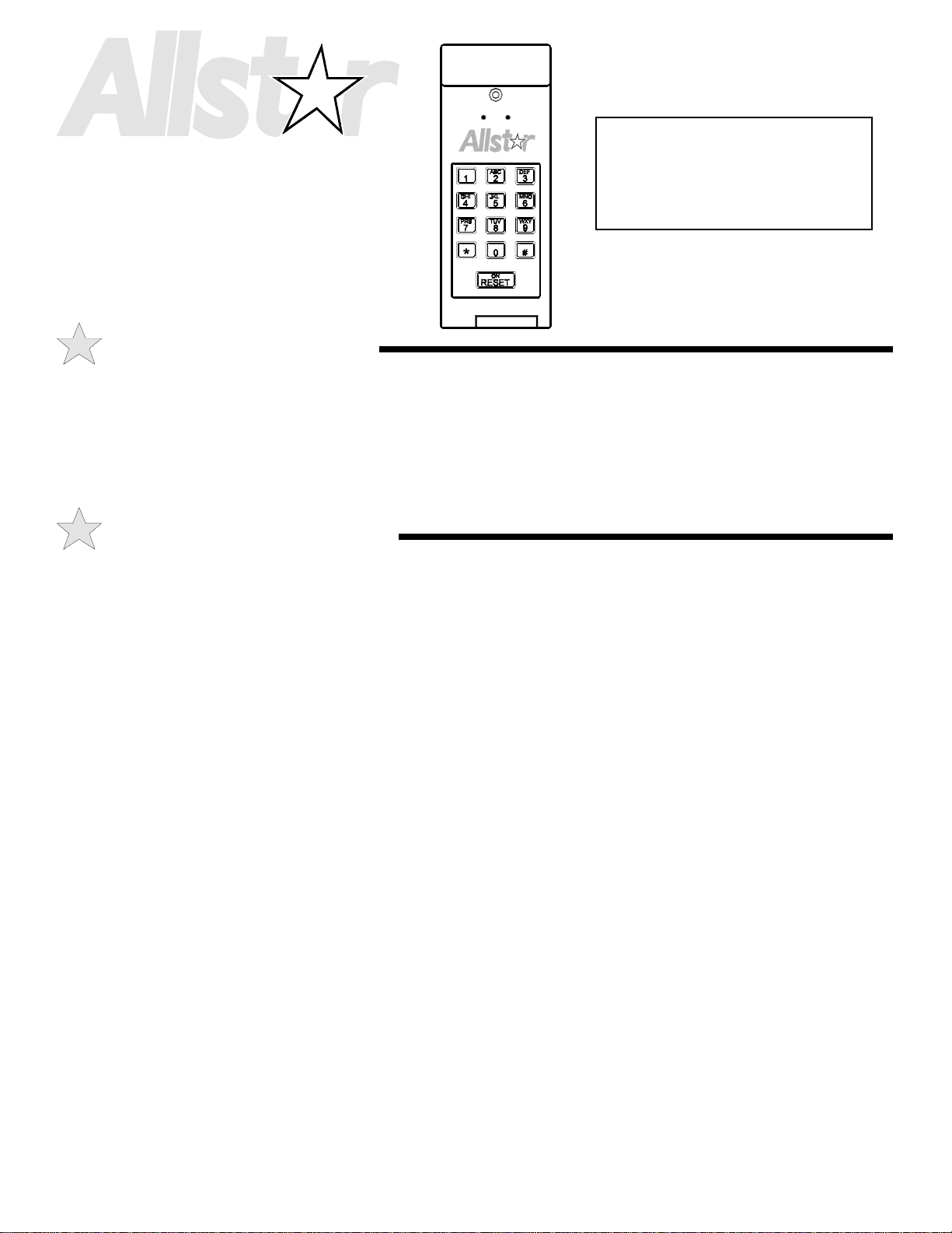
WIRELESS DIGITAL
PROGRAMMABLE
READ THIS MANUAL
. -
CAREFULLY BEFORE
INSTALLATION OR
USE
KEYPAD
Model 104078
PRODUCT FEATURES
The Wireless Digital Programmable Keypad is a high quality, state of the art product with programming capabilities for four separate entrances. We
believe this to be the finest product available anywhere and fully expect that you will receive many years of excellent service from your new keypad.
Because of the programmable nature of your n ew keypad it is important to fol low the programming instructi ons carefully. While they may seem a
little complex at first, if you read these instructions carefully with your keypad close by, you should have little problem setting your new system.
TERMS USED IN THIS MANUAL:
ABOUT YOUR KEYPAD
PIN: Is the Personal Identific a tion Number you choose which will allow
you to operate your door or gate controls. The Primary PIN is the PIN
you choose and program the keypad with to operate the door or gate.
After programming, The Primary PIN becomes the only number which
can be used to re-program your system. It is your insurance against
anyone else re-programming your system.
Factory Default: Refers to settings on your keypad which were made at
the factory.
LED: Light Emitting Diode, or indicator light on your keypad.
FEATURES OF YOUR NEW KEYPAD:
The Keypa d has a num be r of oper a ting features and indicators to provide
you with information and make its overall use easier.
Factory Default Setting: Should you ever forget your PIN you can
restore your key pad to the orig inal factory default settings. Once you do
this, however, you must go through the programming steps again. To
restore the factory default setting PUSH 999, PUSH #, PUSH 999,
PUSH #. All codes are now restored to the original factory settings.
Reset/On-Off Switch: This switch turns the keypad and light system on
allowing you to operate the system as well as to see the keys in the dark.
The keypad will remain lit for 20 seconds after the last key is pressed.
This key is also used to cancel the programming mode if you make a
mistake during the programming process.
Key Press Indicator: This green LED (see Figure 2) will light
whenever a key is pressed indicati ng a valid key entry.
Signal Sent Indicat or: This red LED (see Figure 2) will light whenever
a valid PIN is entered indicating that a radio signal was sent to your
garage door or gate operator.
Incorrect Entry Indicator: Should you ever enter an incorrect PIN
both red and green LED’s will light simultaneously indicating an entry
error. If this should occur please reset the system and enter a valid PIN.
Single Button Mode: Once you have ente re d a valid PIN and y our door
or gate operator begins to function, the number and letter keys remain
active for 20 seconds. Pressing any one of these keys will send another
signal to your operator, thus allowing you maximum control over your
system. Depending on the operator, each signal you send can cause your
operator to either stop or reverse direction. Please see the operating
instructions that came w ith y our oper ator to deter m ine how your opera tor
will react to these inputs.
Low Battery Indicator: The lightin g for your keypad al so serves as a
low battery indicator. Should your keypad lights flash on and off it is an
indication that your batte ry should be changed. If your battery does need
to be replaced, simply open the hatch on the lower right sid e of your unit
(see Figure #2) by sliding it forward, and remove the battery. Replace
the battery w ith a sta ndard 9 Volt transistor battery and repla c e the hatch.
Non-Volatile Memory: Because your new programmable keypad uses
non-volatile memory it is not necessary to reprogram your unit should your
battery fail. Just replace the battery with a new one and your keypad i s ready
to operate again.
INSTALLER: Leave this manual with your customer upon completion of the installation.
1
Page 2
INSTALLATION INSTRUCTIONS
DISCONNECT POWER TO THE OPERATOR BEFORE AND DURING
INSTALLATION OF THIS ACCESSORY. DO NOT RECONNECT POWER
WARNING
TO OPERATOR UNTIL INSTRUCTED TO DO SO. ENSURE DOORWAY IS
CLEAR BEFORE STARTING TESTING OF UNIT.
106495B1
STEP 1: Choose a convenient location that does not
interfere with the normal opening and closing operation of
your door or gate, such as on the door jamb or on the outside
wall adjacent to the door jamb. Please keep in mind that
some doors will swing outward in their travel, and could
damage an improperly located keypad. Try your door first to
ensure there is no possibility of interference.
MOUNT YOUR KEYPAD A
MINIMUM OF 5 FEET ABOVE THE
GROUND TO KEEP IT OUT OF
REACH OF CHILDREN.
106495B2
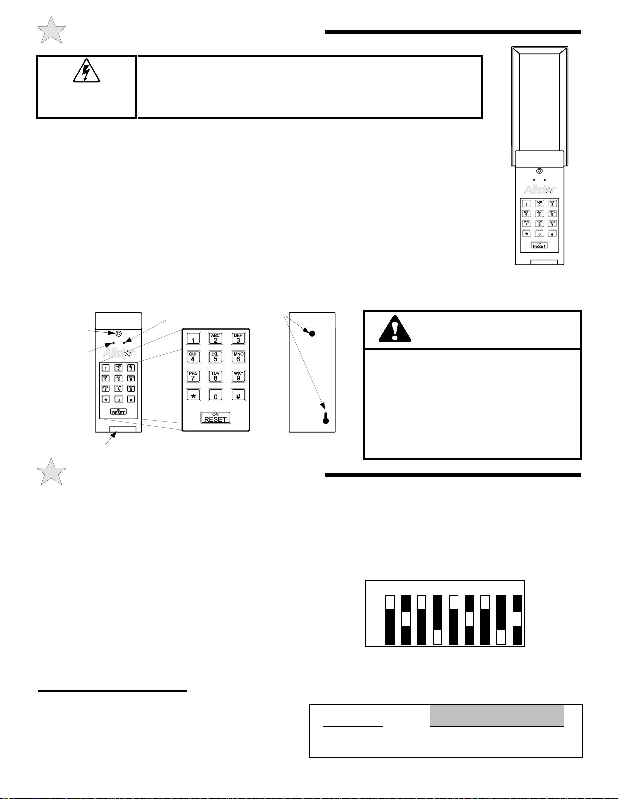
Mounting
Screw Hole
Keypress
Indicator
Figure 2
Battery Hatch
Signal Sent
Indicator
Mounting
Holes
STEP 2: Choose your mounting hardware. The screws
provided are adequate for m ounting y our ke y pad directly into
wood or similar material.
STEP 3: Drill a 3/32 inch pilot hole to a depth of 1-1/2
inches for the bottom mounting screw. Insert the screw into
the pilot hole leaving the head of the screw exposed
approximately 1/8 inch from the wall. Sli de t he keypad over
the exposed screw and position the unit vertically. While
held vertically mark the position of the top hole on the wall.
Remove the keypad and drill another 3/32 inch pilot hole to
a depth of 3/4 inches. Slip the keypad over the bottom screw
and insert the top screw.
Figure 1
WARNING
A CH ILD OPE RATING THE DOOR
CONTROLS RISKS INJURY — OR DEATH
— TO HIMSELF AND OTHERS. DO NOT
ALLOW CHILDREN TO OPERATE ANY
DOOR CONTROLS. MOUNT THE
PUSHBUTTON AT LEAST 5 FT FROM THE
FLOOR, OUT OF R EACH OF CHILDREN .
PROGRAMMING INSTRUCTIONS
The keypad requires you to set two specific security codes. The
Transmitter Code is necessary for your keypad to communicate with
the receiver unit which i s mounted on or in your garage door or gate
operator. The second code is your Personal Identification Number
(PIN) which allows you to activate the system. Your PIN should be
guarded carefully as it is your assurance against unauthorized use of the
system. The factory default PIN is 1,2,3,4 and your unit is set to this
code when you first receive it.
If you look at your keypad you will notice that there are twelve keys, 1
to 9 and 0 plus two specially marked keys * and #. Most of the keys
also have letters printed on them to allow you to set a personal keyword
instead of a PIN. (See Figure 2)
Follow the directions below to first program the Transmitter Code.
PROGRAMMING THE TRANSMITTER CODE
Single Button Transmitter
If your gate or door operator currently has a single button transmitter:
STEP 1: Locate your transmitter a nd open the c oding ha tc h. You w ill
see a coding switch bloc k with numbers from 1 to 9 The possible setting
for each switch is either “+”, “0” or “-”. Translate these settings into a
numeric code:
+ = 1 0 = 2 - = 3
STEP 2:
on the following page.
For example, Figure 3 shows DIP switch settings of:
Copy the transmitter code as it is currently set into the table
+, 0, +, -, +, 0, +, -, 0
1 2 3 4 5 6 7 8 9
+
0
-
The numeric equivalent is: 1, 2, 1, 3, 1, 2, 1, 3, 2
Figure 3
Example Table:
1234 ##112131213 2#
Default PIN DIP Switch Settings from
Transmitter
2
Page 3

PROGRAMMING INSTRUCTIONS
Write the settings of your transmitter DIP switches into the Transmitter Code table:
1234##1 #
Factory Default Your Transmitter Code
STEP 3: Now program your keypad:
1. Press the ON/Reset button.
2. Enter the Factory Default PIN, 1, 2, 3, 4
3. Press key #
4. Press key #
The Transmitter Code is now programmed into your Keypad.
Dual or Triple Button Transmitter
If your gate or door operator has a two or three button transmitter:
5. Press key 1
6. Enter the Transmitter Code you filled in above
7. Press key #
STEP 1: Locate your transmitter a nd open the c oding ha tc h. You w ill
see a coding switch bloc k with numbers from 1 to 8 The possible setting
for each switch is either “+”, “0” or “-”. Translate these settings into a
numeric code:
+ = 1 0 = 2 - = 3
STEP 2:
below.
For example, Figure 4 shows DIP switch settings of:
The numeric equivalent is: 1, 2, 1, 3, 1, 2, 1, 3
Write the settings of your transmitter DIP switches into the Transmitter Code table:
Note the “Transmitter Button Code” box in the table below. You mu st also program the code for the specific transmitter button that you will use to
open the gate or door. On a two button transmitter, the left button code is 1, and right button code is 2. On a three button transmitter the left button
code is 1, the middle button code is 2, and the right button code is 3. If you are programming the keypad so that the left transmitter button opens the
gate or door, you will enter a 1 in the “Transmitter Button Code” box below.
Copy the transmitter code as it is currently set into the table
+, 0, +, -, +, 0, +, -
Example Table:
1234 ##112131213 #
Primary PIN DIP Switch Settings from
1 2 3 4 5 6 7 8
+
0
-
Transmitter
Figure 4
Transmitter
Button Code
1234##1 #
Factory Default Your Transmitter Code
Transmitter Button
Code
STEP 3: Now program your keypad:
1. Press the ON/Reset button.
2. Enter the Factory Default PIN, 1, 2, 3, 4
3. Press key #
4. Press key #
The Transmitter Code is now programmed into your Keypad.
5. Press key 1
6. Enter the Transmitter Code you filled in above
7. Enter the Transmitter Button Code you filled in above
8. Press key #
3
Page 4

PROGRAMMING INSTRUCTIONS
1234#1 #
Factory Default Pin Pin No. New Pin Repeat New Pin
PROGRAMMING YOUR PIN
It is now time to c ha ng e the f a c tor y default PIN of 1, 2, 3, 4 to your own
private PIN.
STEP 1: Begin by filling out the table above.
You may program up to four P IN Codes. The PIN No. entry represents
the first, second, third and fourth PIN you are choosing to program. In
the table above, PIN No. 1 represents the required entry for programming the first PIN you have selected. This first PIN will be your
Primary PIN.
1234#3 5127 5127#
Factory Default Pin Pin No. New Pin Repeat New Pin
A sample block has been filled out below. In this example the
PRIMARY PIN is the factory preset cod e. The P I N No. 3 i nd icates t he
third code in your system (this may be valid even if you do not have a
second code). New PIN Code 5127 is an example representing the new
PIN Code you have chosen.
NOTE: DO NOT REVEAL YOUR PRIMARY PIN CODE.
IT IS THE ONLY NUMBER W HICH CAN BE USED FOR
PROGRAMMING AND IS YOUR INSURANCE AGAINST
ANYONE REPROGRAMMING YOUR KEYPAD.
STEP 2: Press the ON/ RESET bu tton and enter all of the ch aracters
in the sequence shown in the table at the top of the page.
STEP 3: Check your new setting by entering your new PIN Code,
followed by * and the number of the door you wish to activate. The
operator should respond. If not, repeat steps 5 and 6. Press the
RESET/ON button should you press an incorrect key, and begin programming again.
OPERATING INSTRUCTIONS
To operate your new wireless keypad press the RESET/ON key to light
or reset your keypad. Enter your PIN followed by the * symbol and
then your door umber. For example:
ON/RESET
5127 *
1
Activate Keypad Your PIN Door Number
Manufacturer’s Limited Warranty
Allstar warrants its radio controls to be free from defect in material and workmanship for a period of one (1) year from the date of purchase. To obtain service,
contact your dealer.
To obtain service under this warranty the buyer must obtain authorization instructions for the return of any goods from Allstar before return ing the good s. The
goods must be retu rn ed with c omp let e id ent i fi ca t i on, wit h copy of proof-of-p ur ch a se, freigh t prep a id a n d in accordance with Allstar’s instructions or they will not
be accepted. In no event will Allstar be responsible for goods returned without proper authorization or identification.
Goods returned to Allstar for warranty repair within the warranty period, which upon receipt by Allstar are confirmed to be defective and covered by this limited
warranty, will be repaired or replaced at Allstar’s sole option, at no cost and returned pre-paid. Defective parts will be repaired or replaced with new or factory
rebuilt pa rts at Allstar’s sole option.
This limited warranty does not cover non-defect damage, damage caused by unreasonable use, damage caused by improper installation or care, vandalism or
lightning, fire or excessive heat, flood or other acts of God (including, but not limited to misuse, abuse or alterations, failure to provide reasonable and necessary
maintenance), labor charges for dismantling or reinstalling a repaired or replaced unit, or replacement batteries.
These w ar r anties are in lieu of all o the r warranties, either expre ss ed or implied. All implied warranties of merchantabil ity and/or fitness for a par ticul ar pur po s e ar e
hereby disclaimed and excluded. Under no circumstance s s hal l Allstar be liable for cons e quential, incidental or special damages ar ising in connection with the use
or inability to use this product. In no event shall Allstar’s liability for breach of warranty, breach of contract, negligence or strict li abi lity exceed the co st of th e
product covered hereby. No person is authorized to assume for Allstar any other liability in connection with the sale of this product.
This warranty gives you specific legal righ ts. You may also have other rights which vary from state to state. Warranty effective after May 15th, 1997.
For Information:
Your operator should be activated. If not, try again, making certain you
are entering the correct PIN.
If your operator is still not activated, a programming error may have
been made. Repeat the prog ram m ing ste ps outlined in the Program m ing
Instructions section of this manual.
c.p. Allstar Corporation
P.O. Box 240
Downingtown, PA 19335
4
P/N 104096, Rev E, 2/99
 Loading...