

Page 1
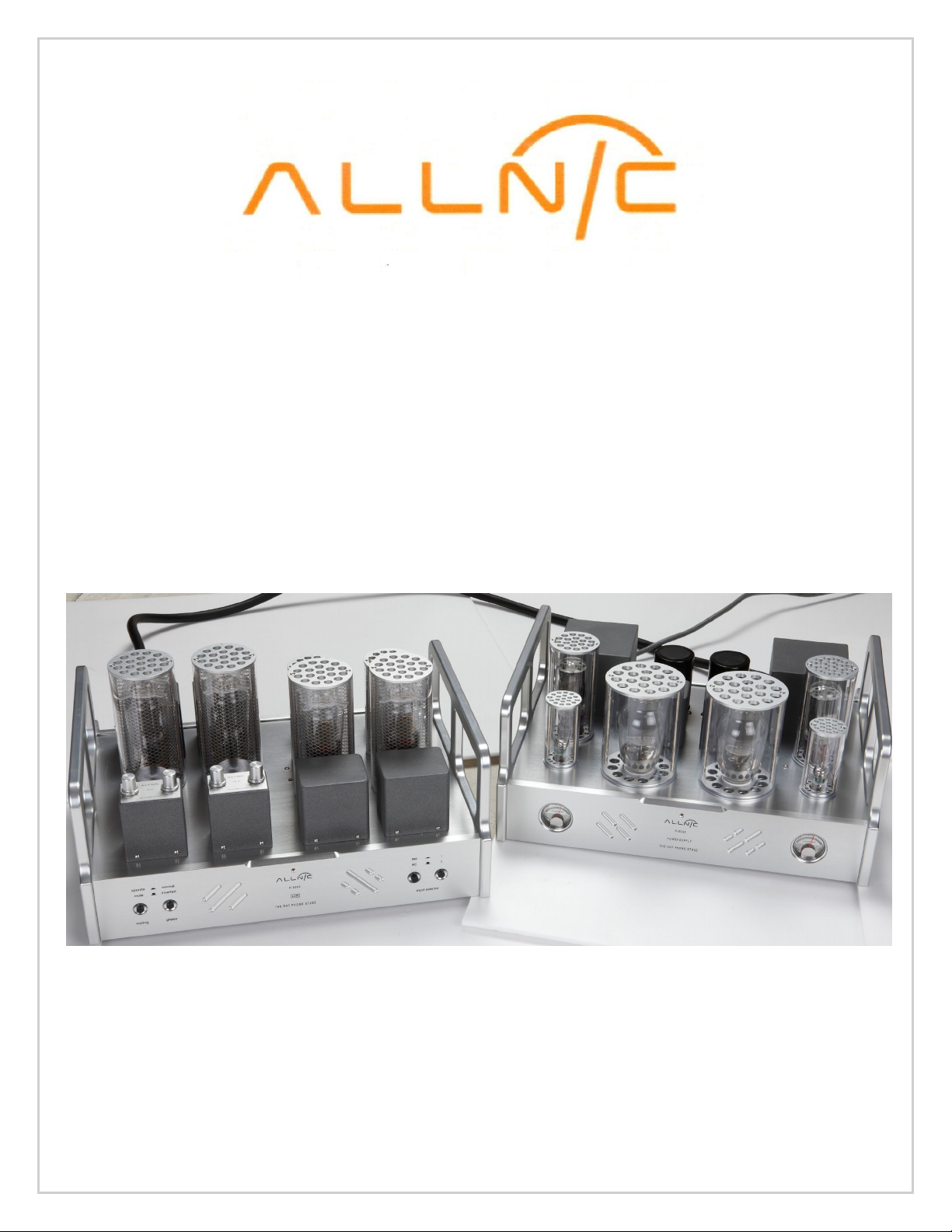
ALLNIC AUDIO
H-8000
DIRECT HEATED TRIODE
PHONO-PREAMPLIFIER
OWNER’S MANUAL
Page 2

ALLNIC AUDIO
H-8000 DIRECT HEATED TRIODE (DHT)
PHONO-STAGE PREAMPLIFIER
Thank you for purchasing the Allnic Audio H-8000 DHT Phono-stage
Preamplifier. We are certain your trust in Allnic Audio and its dealers
worldwide, as well as your appreciation for the sound of this high-quality
device, will be rewarded by its excellent operation for years to come.
Please read this entire manual before you connect the H-8000 DHT Phonostage Preamplifier to the other components of your system and the wall
outlet.
*** Information and specifications for the Allnic Audio product
described in this manual are subject to change without notice.
*** For a list of Allnic Audio distributers around the world, please visit
Allnic Audio’s website:
http://allnicaudio.com
Page 3

TABLE OF CONTENTS:
ALLNIC AUDIO AND THE PURE DIRECT HEATED TRIODE
INTRODUCING THE H-8000 DHT PHONO-STAGE PREAMPLIFIER
3
WHAT’S IN THE BOXES?
5
SAFETY
6
CLEANING
6
INITIAL SET-UP
6
INITIAL POWER ON
9
OPERATION
10
TUBES
11
SPECIFICATIONS
12
WARRANTY
13
TABLES
14
FIGURES
16
BREAKTHROUGH
A. Chassis
B. Connectors
A. Location, Location, Location
B. Power Connections
C. Inputs
D. Outputs
E. Moving Coil (MC) Step-up Transformer Controls
F. Impedance Control
G. A Note on Phase
1
6
7
7
8
8
9
9
Please read about SAFETY before you attempt to use the H-8000 DHT
Phono-stage Preamplifier - we care about our customers and the
equipment, and we want you to enjoy this product for a long time!
Page 4

ALLNIC AUDIO AND THE PURE DIRECT HEATED TRIODE BREAKTHROUGH
In the early years of the last century, the directly heated triode (DHT) was invented independently,
and almost simultaneously, in the USA and Austria. This simple device, an anode, a cathode and a
grid in a vacuum contained in a glass bottle, transformed the world. Over one hundred years later,
the very first triode remains a favourite audio amplification device for devoted music lovers
worldwide.
Debate about the quality of the DHT’s sound reproduction potential continues even today. One of
the interesting aspects of these debates is the degree to which they ignore analysis of common,
fundamental assumptions about DHTs. Those assumptions are based on many decades of circuit
and mechanical experimentation and compromise. Indeed, because of the difficulty of using DHTs
for audio, many circuit design issues have evolved into assumptions about the audio characteristics
of DHTs themselves.
Allnic’s Mr. Kang Su Park has spent a lifetime studying and designing circuits and transformers for
use of DHTs in audio reproduction. Mr. Park has questioned basic assumptions about DHTs, reexamined variations of DHT circuit designs, and researched and experimented rigorously. His work
has resulted in some remarkable audio power amplification devices. For example, Allnic’s 300B
amplifiers produce significantly more power than normally expected. They do this without
shortening tube life because the power increase is not achieved by increased bias. In conjunction
with an increase in power, Mr. Park’s 300B amplifiers also have exceptionally low distortion and
wide bandwidth.
Mr. Park successfully combined elements of what he learned and invented over decades to the
development and production of pure, direct heated triode (DHT) based amplifiers and
preamplifiers. The main breakthrough was the design of a circuit, valve and transformer
combination with astounding measured results. The purity of its square wave reproduction – as
perfect as anything he had ever seen from a DHT valve amplification circuit – had him questioning
what he was seeing! Of course, he replicated these tests many times and recorded them and their
results before assuring himself that there was no mistake.
With such an unprecedented superior outcome for the circuit design, Mr. Park could not be satisfied
placing a DHT stage after one or two stages using indirectly heated triodes. That approach is used in
a number of commercially available preamplifiers using DHTs, but it is a compromise. It does not
result in PURE DHT amplification. It introduces the characteristics of indirectly heated triode sound
into the circuit. The output DHTs are only amplifying a signal already determined by the initial stage
indirectly heated triodes.
In contrast, Mr. Park created amplification devices that used DHTs at each amplification stage. In his
designs, the output stage DHTs do not merely amplify the signal from indirectly heated triode
stages. The Allnic Audio H-8000 is successor to the H-5000, the world’s first commercially produced,
pure DHT phono-preamplifier, from signal input to output.
Differences between the H-5000 DHT and H-8000 DHT:
Improvements have been made to the MC step up transformers, the output transformers and interstage units on the H-8000. In addition, the power transformers and diodes have been “beefed up”
to allow for serious rectifier rolling of the excellent coveted choices from the 1930s, ‘40s and ‘50s.
1
Page 5

Both direct and indirect heated triode 5 Volt, octal-base rectifiers may be used in the H-8000. The
H-8000 is shipped with 5U4G rectifier tubes, which are direct heated. While rectifiers can have
audible effects, the rectifiers are not in the signal path; therefore, even with use of indirect heated
rectifier tubes, the signal path in the H-8000 phono-stage remains pure DHT. Finally, the chassis has
been redesigned to be even more pleasing to the eye.
_________________________________________________________________________________
THE DHT PHONO-STAGE AMPLIFICATION CHALLENGE
Over a century of research and experience, the grand masters of tube design concluded that only a
well-made DHT amplifier can have absolutely the most natural and clear sound. In addition, only the
DHT amplifier could combine that pure, undistorted sound with the ability to reproduce a true 3D
sound stage occupied by life-size images of musical instruments, voices and other recorded sounds.
Successful creation of a complete, or pure, DHT phono-preamplifier has been the final goal, the
dream, of tube master designers – now realized by Allnic Audio.
OVERCOMING THE DIFFICULTIES OF DHT PHONO-STAGE DESIGN
• Rarity of DHT tubes suitable for phono amplification
The essential DHT tubes for phono amplification should have high gain, low internal resistance and
high mutual conductance. It is extremely difficult to make that kind of DHT tube. Among hundreds
of kinds of DHT tubes, there are fewer than 5 that have the specific characteristics required for
phono amplification. To find those tubes requires broad and deep knowledge of tube types and
specifications and much time-consuming experimentation.
• DHTs’ extreme sensitivity to micro-phonic noise
Due to their large, bulky and weak construction, DHT tubes tend to vibrate with the tiniest external
stimuli, so it is almost impossible to use a DHT for phono reproduction without breakthrough
engineering solutions to inhibit sympathetic vibration in the DHT tube. Allnic’s patented GEL tube
damper socket, based on liquid elastomer, mitigate micro-phonic vibrations in the DHT tube.
• Difficulty of properly matching transformers to DHTs
There is no tradition of manufacturing DHT phono-stages, so there are no matching transformers
available in the marketplace. It is, therefore, essential to have in-house capability to design and
wind the transformers specifically required for production of a pure DHT phono-stage. Allnic has
long experience with designing and winding custom transformers, so it is quite natural that a
perfect DHT phono-stage could be made in the Allnic factory. In addition, Allnic has developed and
produces a very small output transformer for DHT phono amplification. The smaller the
transformer, the better sound will be reproduced due to the reduced size of the magnetic field of
the core material, while still providing enough inductance for realistic low frequency reproduction.
• Designing a clean, strong but balanced power supply for noise-free DHT phono amplification
2
Page 6

Since DHT amplification is so sensitive, and has the potential for extremely low noise reproduction,
•
an all tube, high-speed, automatic voltage regulation (AVR) circuit is most appropriate for the power
supply. AVR enhances the signal to noise ratio for noise free operation in dual mono mode. For the
H-8000 phono-stage preamplifier, Allnic uses 300B tubes, a typical DHT, as a series regulator tube in
an AVR circuit. This design results in a superior signal to noise ratio.
_______________________________
INTRODUCING THE H-8000 DHT PHONO-STAGE
The H-8000 is Allnic Audio’s top of the line phono-stage. Like all Allnic Audio products, it uses
Permalloy (iron and nickel alloy) for its signal transformer cores. Allnic is grateful to Mr. G.W.
Elmen of Western Electric for inventing Permalloy for transformer core use, and in so doing,
providing an enormous service to recorded music listeners everywhere.
Key Features of the H-8000 Phono-stage:
LCR TYPE PRE-RIAA AND RIAA EQUALIZATION:
RIAA equalization is a specification for the correct playback of vinyl records, established by the
Recording Industry Association of America. The purpose of the equalization is to permit longer
playback times and improve sound quality. Before the establishment of the RIAA equalization
standard, different production companies utilized different equalization curves.
Vinyl record production equalization is a form of establishing a flat frequency response for the
playback of recorded music. The necessity for this equalization process arises from mechanical
difficulties inherent in record production. In order to prevent the cutting needle from overcutting into the next record groove in the bass, as a record is cut, some bass frequencies are
attenuated. In the treble region, in order for high frequency sounds not to be masked by the
noise inherent in moving a stylus over and through a modulated vinyl surface, some treble
frequencies are boosted. With the application of the correct filtering techniques on playback,
the result is a flat frequency response with better signal to noise ratios.
The H-8000 is equipped with newly developed Allnic “Multi-Curve” LCR units (one for each
channel) which have four (4) Turn-overs (frequency options) and four (4) Roll-offs (gain
reductions in dB). These new units provide for the reproduction of various recording curves
(both for bass attenuation and treble boost) used by different companies prior to the
establishment of the RIAA standard. There are 4 Turn-over options, at: 250Hz, 400Hz, 500Hz
RIAA and 700Hz. There are 4 Roll-off options (at 10KHz): -5dB, -11dB, -13.7dB RIAA and -16dB
(See Figure 7).
• Why LCR?
There are four de-emphasis methods for equalization to that can be applied at playback:
A. Active filters (Negative feedback types):
3
Page 7

Different quantities of negative feedback are applied, with deeper feedback to the high
•
•
•
•
frequencies and shallower to the low frequencies. The benefits of this method are improved
signal to noise ratios, low cost and consistent operation. Some of the shortfalls are looser bass
reproduction and, possibly, a pinched and compressed high frequency playback due to excess
feedback ratios.
B. Passive filters (CR type):
The frequencies are filtered to fit the RIAA specification by varying the amount of attenuation at
different frequencies through a complex capacitor-resistor network. This technique results in no
voltage overload, purer reproduction (because there is no feedback), and more accurate RIAA
compensation. However, there are problems because the system provides no gain, and insertion
loss and impedance matching issues arise.
C. Hybrid filters (use of both CR and negative feedback types):
In this method, both types of filters applied separately; an active filter is applied to the low
frequencies and a passive filter to the high frequencies. Unfortunately, both the advantages and
disadvantages of each of these two types of filters, already discussed, affect the playback system
at the same time.
D. LCR filters, used in the H-8000:
Two pieces of a linear reactor (a kind of choke coil) comprise the main part of these filters,
assisted by precise CR filters, in order to lower impedances and insertion loss.
In vacuum tube circuits, active and passive filters usually are operated on one hundred plus
kilo-ohms of impedance. An LCR equalization filter's impedance is a constant 600 ohms.
Furthermore, an LCR equalization filter's series resistance is less than 13 ohms (as a
comparative, some famous ones are 31 ohms). The lower the impedance, the more dynamic is
the sound reproduction, with better bass response and speed.
But LCR equalization units have drawbacks as well. These drawbacks are high cost and the
difficulty of impedance matching; the latter has been the primary hindrance to the
commercialization of this superb method in the construction of phono-stage amplifiers.
However, Allnic Audio manufactures high quality LCR equalization units in-house and has
developed a 600 ohms impedance matching method.
In addition, the H-8000 also has the following features:
The H-8000 Phono-stage is transformer coupled, with the exception of the first gain
stage, the HL-2K tube.
No negative feedback design with three gain stages
A power supply unit separate from the pure DHT phono-stage itself
High quality MC Step-up Transformers with Permalloy cores are used for the H-8000’s
dual MC inputs.
4
Page 8

•
•
•
•
New vacuum tube damping technology – Allnic Audio’s patented "Absorb GEL tube
damper" technology prevents harmful vibrations from reaching the signal / gain tubes
and, therefore, prevents micro-phonic noise propagation in the tubes. The Allnic Audio
Absorb Gel damper technology effectively solves a problem that plagues most tube
amplification systems. Provided other tube components do not introduce micro-phonic
noise into your system, with the Absorb Gel damping system, you will enjoy a degree of
transparent sound that will surprise and please you.
Pure Class A operation
Pure balanced operation
As are all Allnic Audio products, the H-8000 is fully RoHS (EU Reduction of Hazardous
Substances regulation) compliant in construction and materials.
The H-8000 has been designed and manufactured to work most synergistically with Allnic Audio
preamplifiers, amplifiers, active step-up, and Zero Loss (ZL) cable products.
WHAT’S IN THE BOXES?
Please check that the two (2) shipping boxes contain the following:
• One (1) Allnic H-8000 phono-preamplifier – in natural aluminum or black, depending on
your order specification
• One (1) H-8000 power supply – in natural aluminum or black, depending on your order
specification
• One (1) power umbilical cord (attached to power supply unit)
• One (1) IEC type power cord
• One (1) Owner’s Manual
Note:
1) The H-8000 phono-preamplifier and power supply units ship with the tubes installed.
BEFORE connecting the H-8000 to the wall outlet, please open the chimneys ON BOTH
THE POWER SUPPLY AND THE PHONO-STAGE and remove ALL the paper and Styrofoam
shipping materials from the tubes. It is optional to remove any O rings. Some
customers prefer them on; others, off.
2) The H-8000 power supply will work with most IEC type aftermarket power cords. The
H-8000 is a highly sensitive piece of electronic equipment designed for neutrality and
will output what you put into it. The Allnic ZL-5000 and ZL-3000 power cables will
make an excellent match. Of course, only you can determine the power cord that
works most synergistically with the H-8000 in your system.
3) Be sure the H-8000 power supply unit is labeled for the AC voltage of your location. If it
is not, DO NOT connect the power supply to the AC wall receptacle and contact your
Allnic Audio dealer.
We advise that you keep the boxes and other packing materials that your H-8000 units came
in. They will be useful if you sell your H-8000, or in the unlikely event you need to ship the
units for service.
5
Page 9

SAFETY!!
• BEFORE connecting the H-8000 power supply to the wall outlet, please open the chimneys
ON BOTH THE POWER SUPPLY AND THE PHONO-STAGE and remove the paper and
styrofoam shipping materials from the tubes; the paper packing materials are installed
only to protect the tubes during shipping. It is optional to remove any O rings from the
tubes. Some customers prefer them on; others, off.
• Disconnect power cords by pulling the plug, not the cable.
• Do not attempt any repairs. Do not remove the units’ chassis covers without specific
authorization from your Allnic Audio dealer.
• Keep all cables away from heat sources.
• Ensure there is plenty of free space around and above both the phono-stage and power supply
units.
• Keep the units away from liquids – do not allow any liquid to enter the interior of the units.
• When the units are moved from a cold to a warm environment, allow sufficient time for any
condensation to evaporate in both units before plugging the power supply unit into an AC
connection.
• See the notes on “Location, Location, Location”.
CLEANING
A. Chassis
Use only a soft, lint-free cloth dampened slightly with water only (NO cleaning fluids!) to clean
the faceplate and chassis of the H-8000 and its power supply.
B. Connectors
You may use any good quality contact cleaner recommended for such applications to clean the
contacts from time to time, as you deem appropriate.
INITIAL SET-UP
A. LOCATION, LOCATION, LOCATION
Like all audio products using tubes, the Allnic Audio H-8000 and its power supply need to be placed
on a solid base that is not subject to vibration or sudden shock, and that provides good air
circulation around, above and below both the phono-stage and the power supply.
• DO NOT cover the tops of the H-8000 phono-stage or power supply tube chimneys.
• DO NOT drop the units! For those who may want to place the H-8000 or its power supply on
some kind of after-market isolation feet or similar devices, dropping one side of either of the H8000 units, or the whole of either unit may result in damage to the units or tubes that will not be
covered by warranty.
• DO NOT place the units near a strong light or heat.
• DO NOT place anything heavy on the units.
• DO NOT allow rubber or vinyl materials to rest on either units’ chassis for long periods of time.
This could discolour the metal.
• DO place the units on a shelf or stand that is stable and not subject to vibration or sudden shock.
6
Page 10

• DO consider using a high-quality power cord, as well as inter-connects for both inputs and
outputs. The H-8000 is a highly sensitive piece of electronic designed for neutrality and will
output what you put into it. Allnic’s Zero Loss Technology cables, including the Mu metal
shielded ZL phono cable and interconnects and the high current, low noise ZL-5000 and
ZL-3000 power cords will work synergistically with the H-8000.
• DO try to place the H-8000 and its power supply away from major sources of RFI and EMI;
though well shielded, the H-8000 units will function best away from large power
transformers and other sources of such interference.
B. POWER CONNECTIONS
The H-8000 power supply uses a standard three prong male IEC connection for AC input on the
right hand of the rear of the unit’s chassis. You need a power cord with a female three prong
IEC connector at one end (See Figure 5). The Allnic ZL-5000 and ZL-3000 power cables will
make an excellent match.
The H-8000 power supply connects to the phono-stage itself using the supplied umbilical cable,
fixed to the rear of the power supply. Connect the units to each other by connecting the umbilical
cable to the phono-stage unit using the screw-on connection of the receptacle labeled “DC Source
Input” on the right rear of the phono-stage unit (See Figures 2 and 5).
The H-8000 will be set internally for your location’s electrical system characteristics. Please
check the setting for electrical input on the label on the rear of the power supply to confirm
that your H-8000 matches your location’s electrical system. For North American customers,
the H-8000 power supply is set internally for AC 110/120 volt – 60 HZ operation. There is no
way to change this to another AC setting without return of the unit to the factory for re-wiring,
at the owner’s cost, including transport both directions.
C. INPUTS
There are two (2) sets of two (2) pairs of single-ended (RCA) inputs. Four tonearms can be
connected at the same time. These two pairs are located on the left had side of the rear of the
phono-stage (See Figure 2) and labeled “Input” between and above them. Each channel pair of
inputs is aligned vertically, with the left channel input at the top, labeled “L” and the right channel
input on the bottom, labeled “R”.
The two left hand pairs of inputs (facing the back of the phono-stage) have an “MC” label between
and above the two left channel connectors; these are the two input pairs for a moving coil
cartridge. The right-hand pair of inputs has an “MM” label between and above the left channel
connectors; these are the two input pairs for a moving magnet cartridge. Each pair of moving coil
and moving magnet connections has a number label between the left and right channel input
connections. The “1” pair is to the left of the “2” pair for both MC and MM pairs. These number
labels correspond to the input numbers on the selector knob on the front panel of the phono-stage.
All inputs can be connected at the same time. There are also two screw type, ground connection
pins, one to the left and one to the right of the two sets of MC and MM input connections. Both
ground connections can be connected at the same time.
7
Page 11

When you are facing the front of the H-8000, the two pairs of MC connections are on the right of
the unit, with the two MM connections immediately to their left.
To select the input you want to play, MC1 or MC2 or MM1 or MM2, use the MM or MC and Input 1
or 2 buttons on the right-hand side of the face of the phono-stage (See Figure 1). The left button
selects MM and MC. MM is selected when the button is in the down position. MC is selected when
the button is up. The right button selects input 1 or 2 for whichever cartridge type you have chosen.
Input 1 for the cartridge type is selected when the Input button is in the down position. Input 2 for
the cartridge type is selected when the Input button is up.
For both inputs and outputs, Allnic’s Zero Loss Technology Mu metal shielded ZL interconnects
will work synergistically with the H-8000.
D. OUTPUTS
The H-8000 is equipped with one pair of unbalanced or “single-ended” (RCA) outputs and one pair
of true balanced (XLR) output connections. Each output pair is oriented vertically, with the left
channel output connectors above the right channel output connectors. The left channel output
connectors are labeled “L”, and the right channel output connectors are labeled “R” (See Figure 2).
Each pair of output connections is numbered. The unbalanced (RCA) output connections are labeled
“1”, and the balanced (XLR) connections are labeled “2”.
Immediately to the right of the two pairs of output connections is a switch for selecting either the
balanced or the single-ended output connectors. The switch is labeled to indicate that the upper
position is for the balanced (XLR) output connectors, with the lower position being for the
unbalanced (RCA) output connectors. You may have both balanced and unbalanced outputs
connected at the same time without introducing hum PROVIDED you have the output switch set to
unbalanced output.
E. MOVING COIL (MC) TRANSFORMER CONTROLS AND IMPEDANCE
On the top of each channel’s MC transformer, located on the right rear of the chassis deck of
the phono-stage unit (if you are facing the front of the unit), there is a rotating control (see
Figures 3 and 7). Turn the control knobs to select from four gain factors: +22dB, +26dB, +28dB
and +32dB (x 13, x 20, x 26 and x 40). The four control positions are labeled as both gain and
the turn ratio of the MC transformer; for example, the lowest gain position of +22dB
automatically corresponds to a turn ratio of x13. You should use identical settings for both
transformers to avoid channel imbalance.
Impedance for both MC inputs is fixed at 47 KΩ (Kilo-ohms) and cannot be independently
adjusted. However, impedance varies with the gain adjustment on the transformers, from 29
to 278 ohms (see Table 2). The impedance values in Table 2 represent internal cartridge
impedances, and the highest are at the very extreme of what would normally be expected for
the internal impedance of any MC cartridge.
The MM input pairs are fixed at 47 KΩ impedance.
8
Page 12

NOTE:
Please mute your H-8000, and/or reduce your preamplifier’s volume control, during
transformer gain adjustments. Be aware if you are increasing gain, that you may hit an
uncomfortably loud volume level.
F. PHONO EQUALIZATION CONTROLS
The H-8000’s phono equalization curve controls, of which there are two pairs, one for each
channel, are on top of the transformers located on the left front corner of the phono-stage
unit (if you are facing the front of the unit - see Figures 3 and 8). Use the rotary knobs to set
the equalization for each record. The RIAA standard, which is used for most records, is a Turnover of 500 Hz and Roll-off of -13.7 dB; this standard is indicated for each control knob (See
Figure 3). Be sure to set the controls identically for both channels. A selection of some of the
more common possible non-RIAA settings are found in Table 1 of this manual.
G. A NOTE ON PHASE
Phase issues generally will result in lack of bass and/or focus of the stereo image. You may
need to reverse connections on your cartridge if you are having phase issues. As is usual in
these circumstances, some trial and error experimentation may be required to find the correct
position. The process is simplified for you with the H-8000, as it has a phase control switch on
the front panel of the phono-stage unit (see Figure 1). Switch down is normal; switch up is
inverted.
INITIAL POWER-ON
Once you have your H-8000 phono-preamplifier and power supply units in place, the power
supply is connected to the electrical source, and all connections have been made to your
turntable and preamplifier, you are ready to turn on the power for your H-8000.
Before you power up the H-8000, though, be sure you have:
• removed the packing materials from the tube chimneys ON BOTH THE POWER SUPPLY
AND THE PHONO-STAGE UNITS
• checked that all your connections are snug
• selected the output connections that you want to use, single ended (RCA) or balanced (XLR),
on the switch on the back of the phono-stage (See Figure 2)
• turned the volume down or muted your preamplifier
• pressed the button switch on the left-hand side of the front panel of the phono-stage,
labeled “muting” below and having button in and out icons for operate and mute,
respectively, to the out/up “mute” position (see Figure 1)
• pressed the button switch to the right of the mute button on the left-hand side of the front
panel of the phono-stage to the appropriate phase position, either “normal” (pressed in) or
“inverted” (out position). We suggest starting with “normal” (See Figure 1)
9
Page 13

• set the MM / MC and the Input 1 or 2 buttons on the right side of the face of the phono-
stage to the input you will use initially (See Figure 1), MC1 or MC2 or MM1 or MM2
• if you are using a moving coil cartridge, set the MC transformer controls on the top of the
chassis to the factor that you will try initially
• set the Phono Equalization controls for both channels for the setting for the first record you
will use
To turn on the H-8000, push down the top of the rocker switch on the left-hand panel of the power
supply (facing the front of the unit) near the front of the unit. This is the “on” position. Of course, to
turn the power off, push down the bottom of the rocker switch to its “off”, position.
OPERATION
When the power supply is on, the LED in the top centre of the front panels of both the phonostage and the power supply, and the two current meters on the front panel of the power
supply will illuminate.
To avoid surges to the speakers, it is best to switch between MM or MC input, or between inputs 1
and 2 of either, only with the H-8000 in “mute” mode and with your preamplifier volume down or
muted.
From this point on, operation is straight-forward. All functions except for the MC transformers’ gain
selection and the phono equalization controls are accessed from the front panel. The MC
transformer and equalization controls are accessed from above (see Figure 3). Of course, BE
CAREFUL about differences in gain between your sources. Generally, disc players and tuners will
have greater gain than phono-stages. That means the volume setting for listening to your turntable
might be too high for listening to CDs.
When you are finished listening, turn off your power amplifier(s); then turn off your preamplifier,
and then turn off the H-8000 last by pressing the on-off rocker switch on the right-hand panel of the
power supply (facing it from the front) to its “off” position.
In the case of any failure, please contact your Allnic dealer for assistance.
THE CURRENT METERS
These illuminated meters on the front panel of the power supply indicate the current supply to the
single HL2K and the two KR242 tubes in each channel of the H-8000 power supply. There is one
meter for each channel. The meters will indicate failure or damage to the function of the unit. The
needle should be between the two parallel lines just left of centre on the meter face. Any failure of
the tubes or circuits in one or the other of the H-8000’s power supply channels is indicated by the
needle on the meter for the respective channel moving out from between these two parallel lines.
In the case of any failure indicated by a meter, please contact your Allnic dealer for assistance.
10
Page 14

TUBES
The H-8000 uses the following tubes (See Figures 3 and 6):
Phono-stage:
• Two (2) x HL2K - first gain stage
• Four (4) x KR 242 - second and third gain stages
Power Supply:
• Two (2) x 5U4G – Rectifiers
• Two (2) x 5654 – Voltage error detectors
• Two (2) x 300B - Voltage Regulators
All consequences of changing or attempting to change tubes are borne by the user unless by
express agreement between the owner and Allnic Audio or its authorized representative. Allnic
Audio and its authorized representatives are not liable in any way whatsoever for any injury or loss
incurred by the user or for damage to the H-8000, any of its parts, or tubes or replacement tubes
resulting from the user changing or attempting to change tubes.
11
Page 15

SPECIFICATIONS FOR THE ALLNIC AUDIO H-8000 PHONO-STAGE
Inputs:
• Moving Coil (MC) × two (2) pairs unbalanced (RCA)
• Moving Magnet (MM) x two (2) pairs unbalanced (RCA)
Ground:
• Two (2) x screw type terminals
Outputs:
• One (1) pair x unbalanced (RCA)
• One (1) pair x balanced (XLR)
Frequency Response (RIAA):
• 30Hz ~ 20KHz (±0.5dB)
Voltage Gains:
• MM +44dB (1KHz)
• MC +74dB (1Khz)
Input Impedance:
• MC - up to 200 Ω
• MM – up to 47 KΩ or, upon request, up to 85 KΩ
Maximum Input Voltage:
• MM non-clipping:
• 30 Hz – 10mV
• 100 Hz – 45mV
• 1KHz – 200mV
• 10 KHz – 600 mV
Total Harmonic Distortion (THD):
• Less than 0.3% (1KHz, Output 1V)
Output Impedance:
• 300 Ω (Constant)
Signal to Noise (S/N) Ratio:
• - 80db (CCIR, 1KHz)
Power Consumption:
• 70W at 220 V / 110/120 V / 50 / 60 Hz
12
Page 16

Tubes:
Phono-stage:
• Two (2) x HL2K - first gain stage: no equivalents
• Four (4) x KR242 - second and third gain stages: equivalent is Telefunken RS242 only
Power Supply:
• Two (2) x 5U4G – Rectifiers: equivalents - any 5V octal-base rectifier, indirectly or directly heated.
• Two (2) x 5654 – Voltage error detectors: equivalents are 6AK5W, E95F, M8100, 6096, CK5654,
5654W, GL-5654, CV4010, CV850, 5654RT
• Two (2) x 300B - Voltage Regulators – no equivalents
Fuse:
• AC 2A, 250V
Dimensions:
Phono-stage:
• 430mm (16.9 inches) x 360mm (14.3 inches) x 250mm (10 inches) (W x D x H)
Power supply:
• 430mm (16.9 inches) x 360mm (14.3 inches) x 250mm (10 inches) (W x D x H)
Weight:
Phono-stage:
• 15 Kg (33 lbs.) unpacked; 17.5 Kg (38.5 lbs. in original packing)
Power supply:
• 16.7 Kg (36.77 lbs.) unpacked; 19 Kg (42 lbs. in original packing)
WARRANTY
FOR WARRANTY SERVICE, PLEASE CONTACT YOUR AUTHORIZED ALLNIC DEALER.
All Allnic Audio amplifier products are warranted against materials and manufacturing defects for
parts, excluding tubes, and labour for two (2) years from date of purchase. Tubes are warranted
against materials and manufacturing defects for one (1) year from date of purchase. The warranty
is transferable for the balance of the original purchaser’s warranty period, provided, as stated
below, no unauthorized repairs or modifications have been performed on the product. Date of
purchase is the date indicated on the invoice for the product issued by Allnic Audio or its
authorized representative. For the warranty to be valid, a defective product must be returned to
Allnic Audio’s authorized representative for service prior to any unauthorized attempt to repair.
Any repair work on an Allnic Audio product not specifically authorized by Allnic Audio or its
authorized representative will void the warranty on the product.
13
Page 17

HMV, EMI-ANGEL,
500Hz
-16dB (Sometimes -13.7dB)
500Hz
-11dB
500Hz
-13.7dB
700Hz
-13.7dB
400Hz
-5dB
400Hz
-5dB
400Hz
-11dB
500Hz
(Sometimes 250Hz)
-13.7dB
(Sometimes -11dB or -16dB)
500Hz
-16dB
400Hz
-11dB
Table 1: Some Common Equalization Settings
RECORD LABEL
WESTMINSTER, EPIC, & COLUMBIA
DECCA
L'OISEAU-LYRE
ARGO, RCA (New Orthophonic), &
BRUNSWICK
(RIAA)
RCA (1949-51)
RCA (1951-52)
TELEFUNKEN & (German) DECCA
TURN-OVER
(Early versions 250Hz)
*Early ffrr 700Hz
500Hz
ROLL-OFF
(Early versions 0dB)
-11dB
-13.7dB
PHILIPS
MERCURY
MELODIYA, DG & ETERNA
NARTB
CAPITOL (1942)
∗ This chart is for general reference only and can be changed without prior-notice as more
information becomes available.
∗ Values are rounded in accordance with Allnic measurements.
∗ This Table of Common Equalization Settings has been assembled thanks to kind guidance of MR.
SUNGJUN PARK, the well-known Korean conductor.
14
Page 18
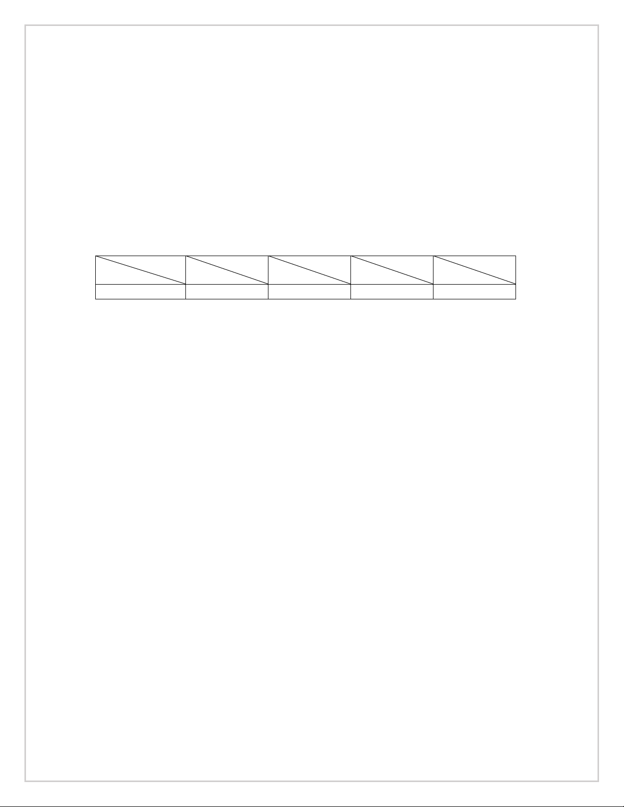
T / R1.
S R2.
1 / 13
+22dB
1 / 20
+26dB
1 / 26
+28dB
1 / 40
+32dB
47 K ohms
278 ohms
117 ohms
70 ohms
29 ohms
Table 2: Impedance Combination Table
1. Turn Ratio of Step-up Transformer
2. Secondary Load Resistor
15
Page 19
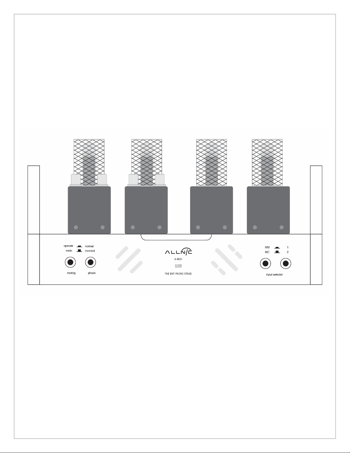
FIGURES
FIGURE 1 – H-8000 DHT Preamplifier Unit Front View
16
Page 20
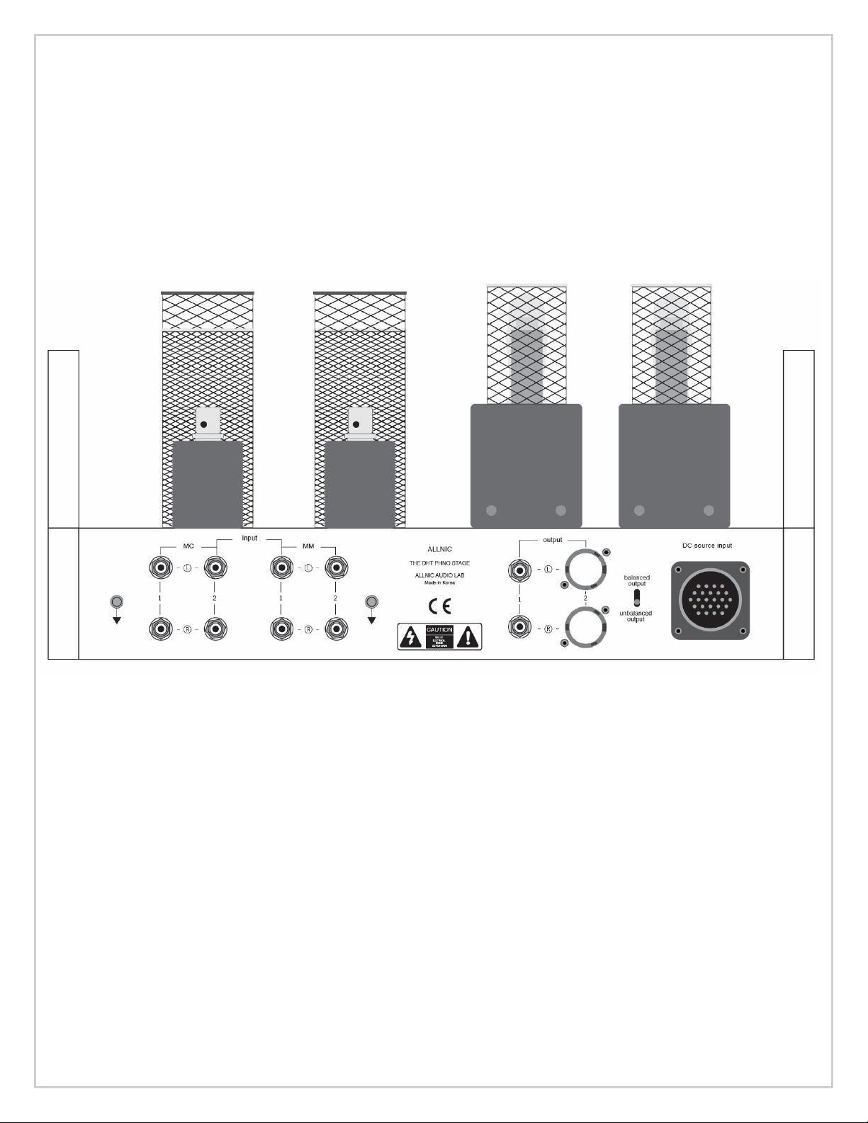
FIGURE 2 – H-8000 DHT Preamplifier Unit Rear View
17
Page 21
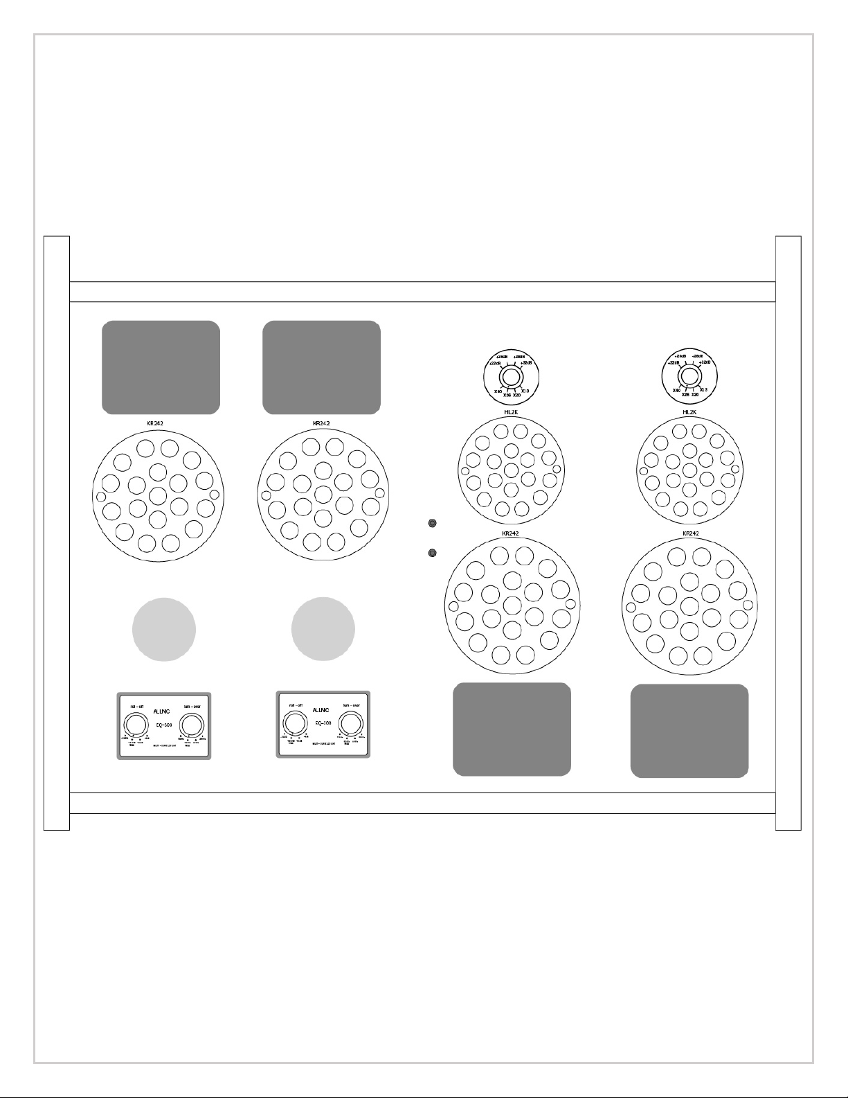
FIGURE 3 – H-8000 DHT Preamplifier Unit Top View
18
Page 22
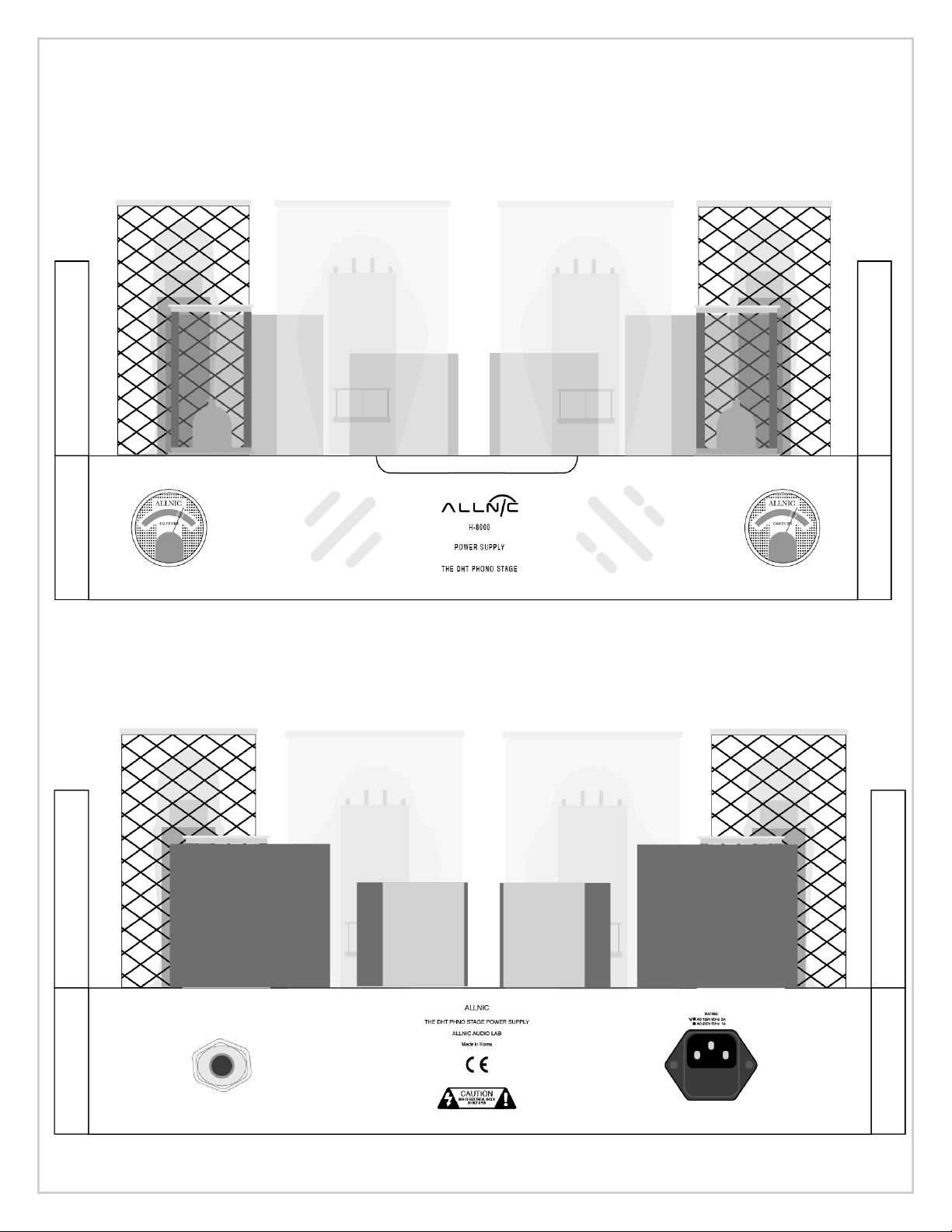
FIGURE 4 – H-8000 DHT Power Supply Front View
FIGURE 5 – H-8000 DHT Power Supply Rear View
19
Page 23
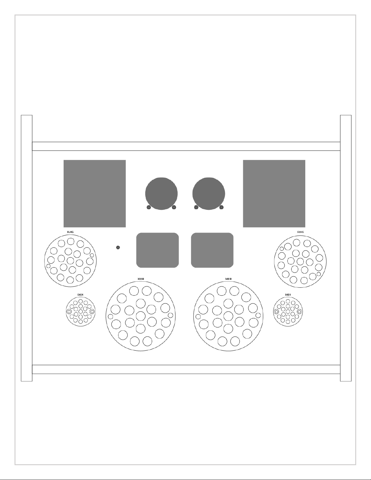
FIGURE 6 – H-8000 DHT Power Supply Top View
20
Page 24
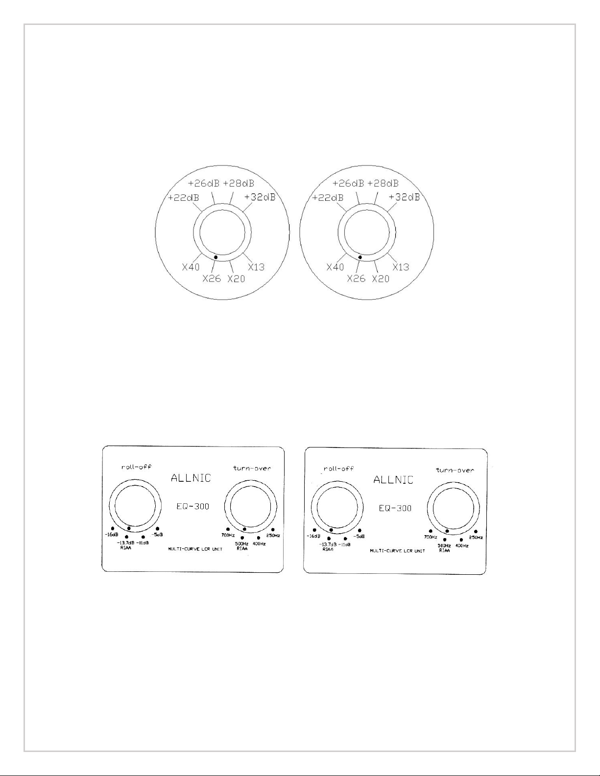
FIGURE 7 – H-8000 DHT Step-up Transformer Gain Controls
FIGURE 8 – H-8000 DHT EQ Controls
 Loading...