

Page 1

ASSEMBLY AND MOUNTING INSTRUCTIONS
GENERAL
•
WARNING-DISCONNECT POWER BEFORE RELAMPING OR
WIRING THE FIXTURE. TURN OFF THE ENTIRE ELECTRICAL
CIRCUIT TO WHICH THE LIGHTING FIXTURE IS ATTACHED
•
INSTALLATION AND MAINTENANCE OF THIS FIXTURE
SHOULD BE COMPLETED BY A LICENSED ELECTRICAN
•
FAILURE TO INSTALL FIXTURE CORRECTLY COULD RESULT IN
SERIOUS INJURY OR DEATH
•
READ ALL INSTRUCTIONS BEFORE STARTING INSTALLATION.
INSTALLATION
STEP 1. Pull the wires out from the outlet box, and install
mounting plate onto the outlet box using the (2)
mounting screws. Strip the Fixture wire ends 5/8”
STEP 2. Fasten bare ground wire to ground wire from the wall
outlet box (usually green or copper color) or connect
ground wire to green screw on the mounting plate.
STEP 3. Connect the neutral (white) fixture wire coming from the
fixture base to neutral (usually white) outlet wire. Fasten
both wires together with a plastic wire nut and tightly
wrap the wire nut with electrical tape.
STEP 4. Repeat the previous step with the hot (black wires).
Make sure there are no exposed wires or strands that
could cause a dangerous short circuit.
FAILURE TO CONNECT THE APPROPRIATE WIRES
CORRECTLY COULD RESULT IN SERIOUS INJURY OR
•
IF AN EXISTING FIXTURE IS BEING REPLACED, REMOVE IT
AND NOTE TO WHICH WIRE IN THE OUTLET BOX THE
ORIGINAL FIXTURE WAS ATTACHED.
•
BEFORE DISCARDING THE CARTON DOUBLE CHECK THE
PACKAGING TO MAKE SURE ALL PARTS HAVE BEEN FOUND.
•
THIS FIXTURE WAS DESIGNED TO BE MOUNTED TO AN
OCTAGON OUTLET BOX. THE BOX MUST BE SECURELY
MOUNTED TO THE STRUCTURE OF THE BUILDING.
DE
ATH!
STEP 5. Carefully place connections back into the outlet box
STEP 6. Place canopy over the mounting plate and secure with
Set Screws
STEP 7. Install the lamp(s). The fixture is rated for 60 watt type A
lamp.
DO NOT EXCEED RECOMMENDED WATTAGE
STEP 8. Unscrew Screw checker and slide the glass cover up
STEP 9. Tilt the glass shade slightly and lift up so the glass
support is inside the glass. Straighten out the Glass
shade and rest on glass support.
STEP 10. Slide down the glass cover and screw the screw checker
back onto the arm.
STEP 11. Restore power to the circuit at breaker or fusebox.
DIMMING
The fixture can be controlled by a wall dimming device. Only use
triac/electronic dimmer. Make sure carton is marked for use with LED
compact fluorescent-incandescent light source only. These can be
CLEANING
Please clean with a soft, dry cloth ONLY! Do not use cleaning products.
provided by your local electrical distributor, home center, or
hardware store.
Page 2
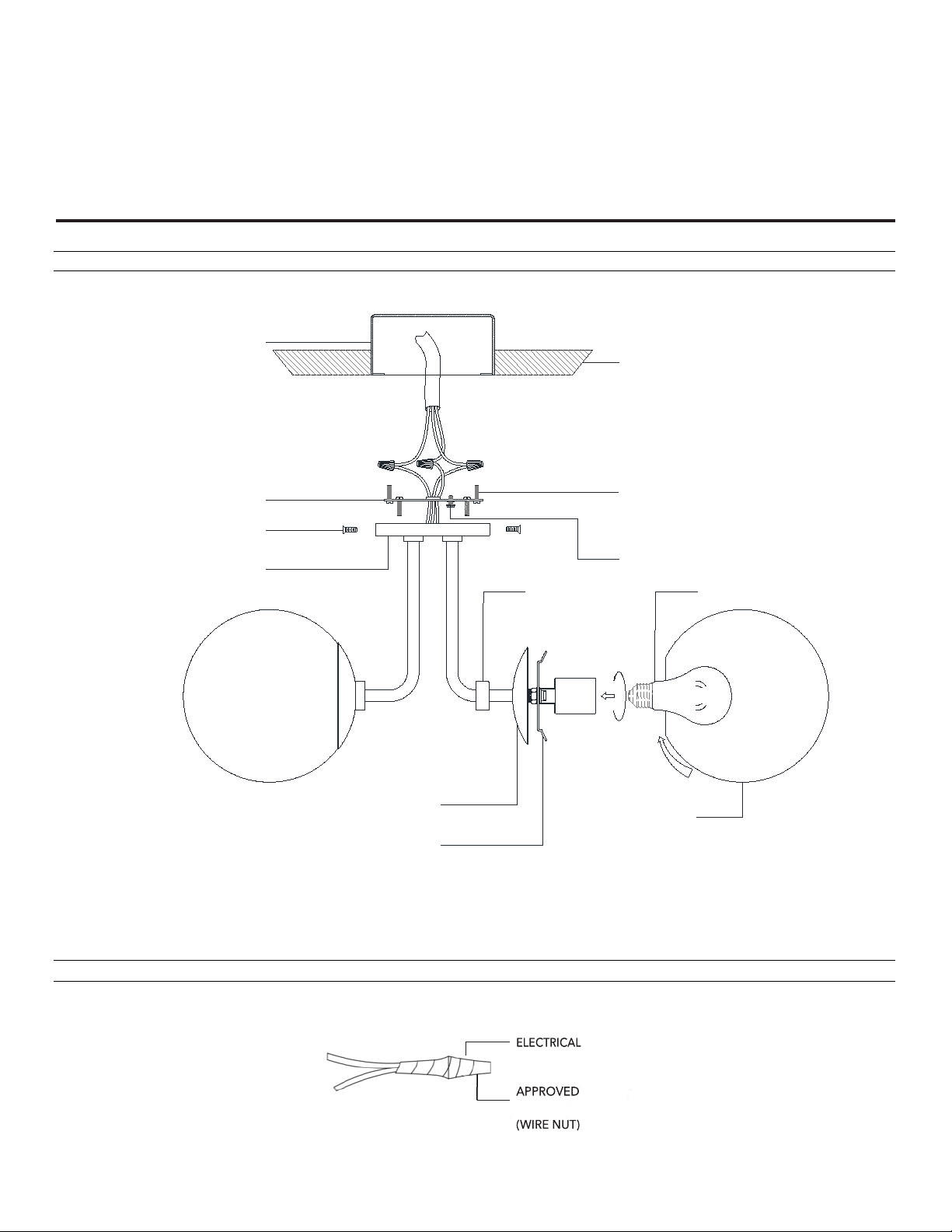
ASSEMBLY AND MOUNTING DIAGRAM
OUTLET BOX
CEILING
MOUNTING PLATE
MOUNTING SCREWS
GROUND SCREW
LAMP
CANOPY
GLASS SUPPORT
GLASS COVER
SET SCREWS
GLASS SHADE
SCREW
CHECKER
WIRE NUT/TAPING DIAGRAM
TAPE
FASTNER
Page 3

NOTICE D'ASSEMBLAGE ET DE MONTAGE
Retirer les fils de la boîte de dérivation et installer la plaque
de montage sur la boîte de dérivation au moyen des (2) vis
de montage.
Fixer le fil de terre dénudé au fil de terre de la boîte de
dérivation à la paroi (généralement de couleur verte ou
cuivre) ou relier le fil de terre à la vis verte sur la plaque de
montage.
Relier le fil neutre (blanc) venant de la base du dispositif au
fil neutre (généralement blanc) de la boîte de dérivation.
Relier les deux fils entre eux à l’aide d’un serre
plastique et envelopper le serre
serré.
Répéter le pas précédent avec les fils de phase (noirs
S’assurer qu’il n’y a pas de fils exposés ou de brins
qui pourraient causer un dangereux court
UNE CONNEXION INCORRECTE OU D
PEUT ENTRAÎ
Remettre soigneusement les connexions dans la boîte de
dérivation
Placer le cache
place à l’aide des vis de fixation.
Installer la ou les ampoules. Le dispositif est prévu pour des
ampoules de 60 watt de type A.
NE PAS DÉPASSER LE WATTAGE RECOMMANDÉ!
Dévisse
et glisser le pavillon de verre vers le
haut.
Incliner légèrement l’abat
que le support du verre se trouve à l’intérieur
Redresser l’abat
de verre.
Gli
à vis au bras.
Rebrancher le couran
fusibles.
PAS 1.
PAS 5.
GENERALITÉ
•
AVERTISSEMENT - DÉBRANCHER LE COURANT AVANT DE
RE
MPLACER UNE AMPOULE OU DE RELIER LE DISPOSITIF AU
COURANT. COUPER INTÉGRALEMENT LE CIRCUIT ÉLÉCTRIQUE
AUQUEL LE DISPOSITIF EST RELIÉ.
•
L'INSTALLATION ET L'ENTRETIEN D E CE DISPOS I TIF DOIVENT ÊTRE
RE
ALISÉS PAR UN ÉLECTRICIEN AGRÉÉ.
•
UNE INSTALLATION INCORRECTE DE L'APPAREIL PEUT ENTRAINER
DES BLESSURES GRAVES OU LA MORT.
EUILLER LIRE TOUTE LA NOTICE AVANT DE PROCEDER À
V
•
L'INSTALLATION.
INSTALLATION
•
EN CAS DE REMPLACEMENT D'UN APPAREIL EXISTANT RETIRER
CELUI-CI ET NOTER À QUELS CÂBLES DE LA BOîTE DE DÉRIVATION
LE DISPOSITIF ORIGINAL ÉTAIT RELIÉ.
•
AVANT DE JETER LA BOÎTE D'EMBALLAGE, CONTRÔLER
L'EMBALLAGE POUR S'ASSURER QUE TOUTES LES PIÈCES ONT ÉTÉ
TROUVÉES.
CE DISPOSITIF A ÉTÉ CONÇU POUR ÊTRE MONTÉ SUR UN
•
BOÎTE DE DÉRIVATION OCTOGONALE. LA BOÎTE DOIT ÊTRE
FIXÉE DE MANIÈRE SÛRE À LA STRUCTURE DE L'IMMEUBLE.
E
STEP 1. Pull the wires out from the outlet box, and install
STEP 2. Fasten bare ground wire to ground wire from the wall
PAS 2.
STEP 3. Connect the neutral (white) fixture wire coming from the
P
AS 3.
STEP 4. Repeat the previous step with the hot (black wires). Make
AS 4.
P
STEP 5. Carefully place connections back into the outlet box
STEP 6. Place canopy over the mounting plate and secure with
STEP 7. Install the lamp(s). The fixture is rated for 60 watt type A
RÈGLAGE D’INTENSITÉ
Le dispositif peut être contrôlé par un variateur de lumière de paroi. incadescente. Celle-ci peuvent être fournies par votre distributeur
N’utiliser qu’un variateur de lumière triad/électronique. S’assurer de matériel électrique local, par un centre de bricolage ou par une
que l’emballage porte la mention précisant de n’utiliser le dispositif quincaillerie.
qu’avec une source lumineuse LED compact fluorescente
NETTOYAGE
A nettoyer UNIQUEMENT avec un chiffon doux et sec! Ne pas utiliser de produits de nettoyage.
mounting plate onto the outlet box using the (2)
mounting screws. Strip the Fixture wire ends 5/8”
outlet box (usually green or copper color) or connect
ground wire to green screw on the mounting plate.
fixture base to neutral (usually white) outlet wire. Fasten
both wires together with a plastic wire nut and tightly
wrap the wire nut with electrical tape.
sure there are no exposed wires or strands that could
cause a dangerous short circuit.
FAILURE TO CONNECT THE APPROPRIATE WIRES
CORRECTLY COULD RESULT IN SEROIUS INJURY OR DEATH!
Set Screws
Dénuder chaque fil jusqu’à 1,6cm (5/8”)
-câble de ruban isolant bien
ES FILS INAPPROPRIÉS
NER DE GRAVES BLESSURES OU LA MORT!
-câble en
-circuit.
lamp.
.
PAS 6.
STEP 8. Unscrew Screw checker and slide the glass cover up
STEP 9. Tilt the glass shade slightly and lift up so the glass
PAS 7.
STEP 10. Slide down the glass cover and screw the screw checker
PAS 8.
STEP 11. Restore power to the circuit at breaker or fusebox.
PAS 9.
).
AS 10.
P
P
AS 11.
DO NOT EXCEED RECOMMENDED WATTAGE
support is inside the glass. Straighten out the Glass shade
and rest on glass support.
back onto the arm.
sser vers le bas le pavillon de verre et revisser la bague
-piton sur la plaque de montage et fixer en
r la bague à vis
-jour en verre et le soulever afin
du verre.
-jour en verre et le reposer sur le support
t au disjoncteur ou à la boîte
Page 4
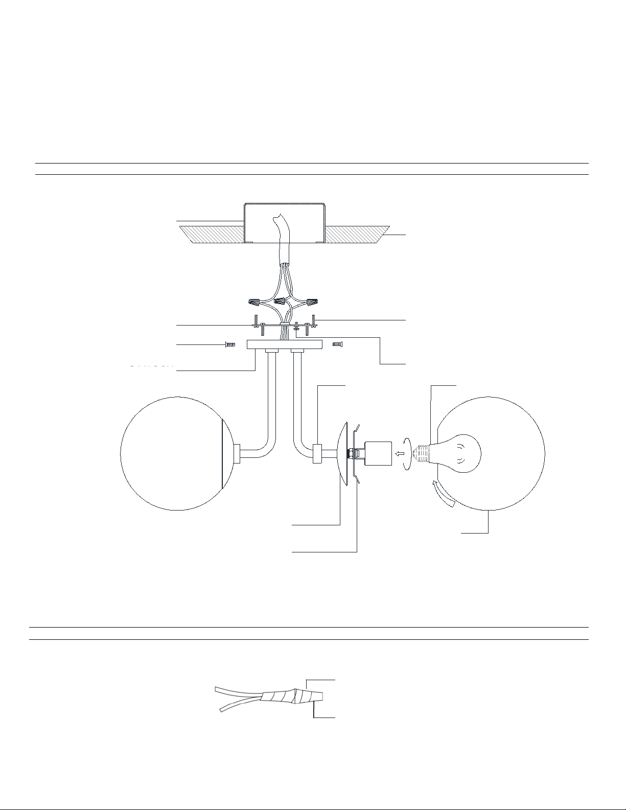
SCHÉMA D’ASSEMB LAG E ET D E M ONTA GE
OUTLET BOX
CEILING
MOUNTING PLATE
MO UN TIN G SCREWS
GROUND SCREW
LAMP
CANOPY
GLASS SUPPORT
GLASS COVER
SET SCREWS
GLASS SHADE
SCREW
CHECKER
CACHE-PITON
VIS DE MONTAGE
VIS DE MONTAGE
PLAQUE DE MONTAGE
BOÎTE DE DÉRIVATION
PLAFOND
ABAT-JOUR
SUPPORT DE VERRE
V IS DE MISE À TERRE
VIS À BAGUE
CONNECTEUR APPROVÉ
RUBAN ISOLANT
AMPOULE
SCHÉMA DE BORNE DE RACCORDEMENT ET D’ENVELOPPAGE AVEC RUBAN ISOLANT
PAVILLON DE VERRE
EN VERRE
ELECTRICAL
APPROVED
(BORNE DE RACCORDEMENT)
FASTNER
(WIRE NUT)
TAPE
 Loading...