

Page 1

AVT Prosilica GT
Allied Vision Technologies GmbH
Taschenweg 2a
D-07646 Stadtroda, Germany
Technical Manual
AVT GigE Vision Cameras
V2.1.0
28 October 2013
Page 2

Legal notice
For customers in the U.S.A.
This equipment has been tested and found to comply with the limits for a Class A digital device,
pursuant to Part 15 of the FCC Rules. These limits are designed to provide reasonable protection
against harmful interference when the equipment is operated in a residential environment. This
equipment generates, uses, and can radiate radio frequency energy and, if not installed and used
in accordance with the instruction manual, may cause harmful interference to radio communications. However, there is no guarantee that interferences will not occur in a particular installation.
If the equipment does cause harmful interference to radio or television reception, the user is
encouraged to try to correct the interference by one or more of the following measures:
• Reorient or relocate the receiving antenna.
• Increase the distance between the equipment and the receiver.
• Use a different line outlet for the receiver.
• Consult a radio or TV technician for help.
You are cautioned that any changes or modifications not expressly approved in this manual could
void your authority to operate this equipment. The shielded interface cable recommended in this
manual must be used with this equipment in order to comply with the limits for a computing
device pursuant to Subpart A of Part 15 of FCC Rules.
For customers in Canada
This apparatus complies with the Class A limits for radio noise emissions set out in the Radio Interference Regulations.
Pour utilisateurs au Canada
Cet appareil est conforme aux normes classe A pour bruits radioélectriques, spécifiées dans le
Règlement sur le brouillage radioélectrique.
Life support applications
These products are not designed for use in life support appliances, devices, or systems where malfunction of these products can reasonably be expected to result in personal injury. Allied Vision
Technologies customers using or selling these products for use in such applications do so at their
own risk and agree to fully indemnify Allied Vision Technologies for any damages resulting from
such improper use or sale.
Trademarks
Unless stated otherwise, all trademarks appearing in this document of Allied Vision Technologies
are brands protected by law.
Warranty
The information provided by Allied Vision Technologies is supplied without any guarantees or
warranty whatsoever, be it specific or implicit. Also, excluded are all implicit warranties concerning the negotiability, the suitability for specific applications or the non-breaking of laws and patents. Even if we assume that the information supplied to us is accurate, errors and inaccuracy may
still occur.
Copyright
All texts, pictures and graphics are protected by copyright and other laws protecting intellectual
property. It is not permitted to copy or modify them for trade use or transfer, nor may they be used
on websites.
Allied Vision Technologies GmbH 10/2013
All rights reserved.
Managing Director: Mr. Frank Grube
Tax ID: DE 184383113
Headquarters:
Taschenweg 2a
D-07646 Stadtroda, Germany
Tel: +49 (0)36428 6770
Fax: +49 (0)36428 677-28
e-mail: info@alliedvisiontec.com
AVT Prosilica GT V2.1.0
2
Page 3

Contents
Contacting Allied Vision Technologies ................................................... 5
Introduction ............................................................................................................ 6
Document history............................................................................................................ 6
Conventions used in this manual ........................................................................................ 8
Precautions.................................................................................................................... 9
Cleaning optics............................................................................................................. 10
Conformity ..............................................................................................................12
Specifications .......................................................................................................13
Prosilica GT1290/1290C ................................................................................................. 13
Prosilica GT1380/1380C ................................................................................................. 15
Prosilica GT1600/1600C ................................................................................................. 17
Prosilica GT1660/1660C ................................................................................................. 19
Prosilica GT1910/1910C ................................................................................................. 21
Prosilica GT1920/1920C ................................................................................................. 23
Prosilica GT2000 / 2000C / 2000 NIR ................................................................................. 25
Prosilica GT2050 / 2050C / 2050 NIR ................................................................................. 27
Prosilica GT2300/2300C ................................................................................................. 29
Prosilica GT2450/2450C ................................................................................................. 31
Prosilica GT2750/2750C ................................................................................................. 33
Prosilica GT3300/3300C ................................................................................................. 35
Prosilica GT3400/3400C ................................................................................................. 37
Prosilica GT4100/4100C - Preliminary................................................................................ 39
Prosilica GT4905/4905C ................................................................................................. 40
Prosilica GT4907/4907C ................................................................................................. 42
Prosilica GT6600/6600C ................................................................................................. 44
Camera attribute highlights ........................................................................46
Filters ........................................................................................................................47
Camera dimensions ..........................................................................................48
Prosilica GT standard cameras (C-Mount) ........................................................................... 48
Prosilica GT long cameras................................................................................................ 49
Prosilica GT large format cameras ..................................................................................... 51
Optical flange focal distance ........................................................................................... 52
Tripod adapter.............................................................................................................. 55
Adjustment of C/CS-Mount ............................................................................................. 56
Adjustment of F-Mount................................................................................................... 57
Camera interfaces .............................................................................................58
AVT Prosilica GT Technical Manual V2.1.0
3
Page 4

Status LEDs .................................................................................................................. 58
Gigabit Ethernet port ..................................................................................................... 59
Camera I/O connector pin assignment ............................................................................... 60
I/O definition ............................................................................................................... 61
Lens control................................................................................................................. 64
Camera trigger.....................................................................................................68
Input: Non-isolated and opto-isolated internal circuit.......................................................... 68
Output: Non-isolated internal circuit................................................................................. 69
Output: Opto-isolated internal circuit................................................................................ 69
Trigger timing diagram................................................................................................... 70
Firmware update.................................................................................................72
Resolution and ROI frame rates ...............................................................73
Prosilica GT1290 ........................................................................................................... 74
Prosilica GT1380 ........................................................................................................... 75
Prosilica GT1600 ........................................................................................................... 76
Prosilica GT1660 ........................................................................................................... 77
Prosilica GT1910 ........................................................................................................... 78
Prosilica GT1920 ........................................................................................................... 79
Prosilica GT2000 ........................................................................................................... 80
Prosilica GT2050 ........................................................................................................... 81
Prosilica GT2300 ........................................................................................................... 82
Prosilica GT2450 ........................................................................................................... 83
Prosilica GT2750 ........................................................................................................... 84
Prosilica GT3300 ........................................................................................................... 85
Prosilica GT3400 ........................................................................................................... 86
Prosilica GT4905 ........................................................................................................... 87
Prosilica GT4907 ........................................................................................................... 88
Prosilica GT6600 ........................................................................................................... 89
Prosilica GT model comparison ........................................................................................ 90
Description of the data path........................................................................91
Prosilica GT monochrome cameras .................................................................................... 91
Prosilica GT color cameras ............................................................................................... 92
Appendix..................................................................................................................93
Sensor position accuracy of Prosilica GT standard and long cameras ........................................ 93
Additional references ......................................................................................94
Index...........................................................................................................................95
AVT Prosilica GT Technical Manual V2.1.0
4
Page 5

Contacting Allied Vision Technologies
Contacting Allied Vision Technologies
Info
• Technical information:
http://www.alliedvisiontec.com
• Support:
support@alliedvisiontec.com
Allied Vision Technologies GmbH (Headquarters)
Taschenweg 2a
07646 Stadtroda, Germany
Tel: +49 36428-677-0
Fax: +49 36428-677-28
e-mail: info@alliedvisiontec.com
Allied Vision Technologies Canada Inc.
101-3750 North Fraser Way
Burnaby, BC, V5J 5E9, Canada
Tel: +1 604-875-8855
Fax: +1 604-875-8856
e-mail: info@alliedvisiontec.com
Allied Vision Technologies Inc.
38 Washington Street
Newburyport, MA 01950, USA
Toll Free number +1 877-USA-1394
Tel: +1 978-225-2030
Fax: +1 978-225-2029
e-mail: info@alliedvisiontec.com
Allied Vision Technologies Asia Pte. Ltd.
82 Playfair Road
#07-02 D’Lithium, Singapore 368001
Tel: +65 6634-9027
Fax: +65 6634-9029
e-mail: info@alliedvisiontec.com
Allied Vision Technologies (Shanghai) Co. Ltd.
2-2109 Hongwell International Plaza
1602# ZhongShanXi Road, Shanghai 200235, China
Tel: +86 21-64861133
Fax: +86 21-54233670
e-mail: info@alliedvisiontec.com
AVT Prosilica GT Technical Manual V2.1.0
5
Page 6
Introduction
Introduction
This AVT Prosilica GT Technical Manual describes in depth the technical specifications of this camera family including dimensions, feature overview, I/O definition, trigger timing waveforms, and frame rate performance.
For information on software installation read the AVT GigE Installation Man-
ual. For detailed information on camera features and controls specific to the
Prosilica GT refer to the AVT GigE Camera and Driver Features and AVT GigE
Camera and Driver Attributes documents.
www
AVT Prosilica GT literature:
http://www.alliedvisiontec.com/us/support/downloads/
product-literature/prosilica-GT.html
Document history
Version Date Remarks
V2.0.0 2011-Dec-12 New Manual - RELEASE status
V2.0.1 2012-Mar-08 • Added spectral response curves
• Added GT1910, GT1920, GT2300, GT2750 frame rate charts
V2.0.2 2012-May-31 • Added GT3300, GT1660
V2.0.3 2012- Jun-21
V2.0.4 2012-Sep-21 • Added GT2000, GT2050, GT6600
V2.0.5 2013-Jan-14 • Added GT3400, GT4100, GT4905, GT4907
• Added DC Iris information
• Link added to RS-232 application note
• Added lens control port wiring
• Renamed Camera IO signals
• Updated the circuits diagrams in the Camera trigger section:
Figure 45, Figure 48, Figure 49, Figure 50
• Updated the Prosilica GT trigger circuit values: Table 21
• Removed the Supported P-Iris section
• Updated the Exposure control values
V2.0.6 2013-Feb-12 • Added Status LEDs section
• Updated the RoHS directive
Table 1: Document history
AVT Prosilica GT Technical Manual V2.1.0
6
Page 7

Introduction
Version Date Remarks
V2.0.7 2013-May-16 • Updated the bit depth and exposure control camera specifica-
tions in the Specifications chapter
• Updated pixel format naming according to the GenICam naming convention
• Corrected body dimensions and mass for GT3400 on page 37
• Corrected the spectral plots for GT3400 on page 38
• Added VIMBA SDK link in Additional references section
• Added frame rate vs. height graphs for Prosilica GT3400, Prosil-
ica GT4905, Prosilica GT4907
• Updated frame rate vs. height graphs in Resolution and ROI
frame rates chapter
• Updated AVT recommended cabling to Category 6 or higher in
Gigabit Ethernet port section
V2.0.8 2013-Jul-05 • Added contact information for Allied Vision Technologies
(Shanghai) Co. Ltd.
• Updated spectral plots for GT1910 on page 22
• Updated the links to AVT GigE Installation Manual
•Added links to AVT GigE Camera and Driver Features document
V2.0.9 2013-Sep-16 • Updated chapter Camera dimensions on page 48
• Updated Lens control section page 64
• Updated Color cameras with IR filter section on page 10
• Updated the specifications for GT2000C and GT2050C on page
25 and 27
• Added a note on the locking screw cables on page 59
• Added optical flange focal distance and maximum lens protrusion information for C-/F-Mount on page 52
• Added 1 inch lens format recommendation for Prosilica GT2000
cameras on page 25
• Added temperature monitoring information in the Specifica-
tions chapter
• Updated specifications for Prosilica GT2000 / 2000C / 2000 NIR
and Prosilica GT2050 / 2050C / 2050 NIR cameras
• Added frame rate tables in chapter Resolution and ROI frame
rates on page 73
• Added chapter Appendix on page 93
V2.1.0 2013-Oct-28 • Updated table 20 on page 46
• Added chapter Description of the data path on page 91
•Added section Adjustment of F-Mount on page 57
Table 1: Document history
AVT Prosilica GT Technical Manual V2.1.0
7
Page 8
Introduction
Conventions used in this manual
To give this manual an easily understood layout and to emphasize important
information, the following typographical styles and symbols are used:
Styles
Style Function Example
Bold Programs, inputs, or
highlighting important
information
Courier Code listings etc. Input
Upper case Register REGISTER
Italics Modes, fields Mode
Parentheses and/or blue Links (Link)
Table 2: Styles
bold
Symbols
Note
This symbol highlights important information.
Caution
This symbol highlights important instructions. You have to follow these instructions to avoid malfunctions.
www
This symbol highlights URLs for further information. The URL
itself is shown in blue.
Example:
http://www.alliedvisiontec.com
AVT Prosilica GT Technical Manual V2.1.0
8
Page 9

Introduction
Precautions
Caution
Caution
Caution
Caution
Do not disassemble the camera housing. Warranty is void if
camera has been disassembled.
This camera contains sensitive internal components.
Keep shipping material.
Poor packaging of the product may cause damage during
shipping.
Verify all external connections.
Verify all external connections in terms of voltage levels,
power requirements, voltage polarity, and signal integrity
prior to powering the device.
Cleaning.
This product can be damaged by some volatile cleaning agents.
Avoid cleaning the image sensor unless absolutely necessary.
Please see instructions on optics cleaning in this document.
Caution
Do not exceed environmental specifications.
See environmental specifications limits in the Specifications
section of this document. Special care must be taken to
maintain a reasonable operating temperature. If the camera
is operated in temperatures higher than the specified range,
the camera should be mounted on a heat sink.
For more information on camera body temperature:
http://www.alliedvisiontec.com/fileadmin/content/PDF/
Support/Application_Notes/AppNote__Prosilica_GT_Body_Temperature.pdf
AVT Prosilica GT Technical Manual V2.1.0
9
Page 10

Introduction
Cleaning optics
Caution
AVT does not warranty against any physical damage to the sensor/filter/protection glass or lenses. Use utmost care when
cleaning optical components.
Caution
Do not touch any optics with fingers. Oil from fingers can
damage fragile optical coatings.
Identifying debris
Debris on the image sensor or optical components appears as a darkened area
or smudge on a camera image. Do not confuse this with a pixel defect which
appears as a distinct point.
Locating debris
First determine whether the debris is on the sensor glass, IR filter (if used), or
lens. The farther away the debris is from the sensor, the blurrier the debris
appears on a camera image.
Stream a live image from the camera using a uniform target, such as a piece of
paper. To determine if the debris is on the camera lens, rotate the lens independent of the camera. If the spot moves, the debris is on the lens. Otherwise, the
debris is on the IR filter (if used) or sensor glass.
Color cameras with IR filter
Prosilica GT color cameras are equipped with an IR filter. With no lens or lens
cap on a camera, the IR filter is exposed and debris can accumulate on it. This is
the most probable location for debris. It should not be necessary to remove the
IR filter for cleaning. Clean the outside of the IR filter glass using the techniques explained in the next section. If it is determined that the debris is on the
inside surface of the filter glass, or on the sensor glass, IR filter removal is necessary.
Note
• A pin spanner wrench (AVT P/N: E9020001) suitable
for IR filter removal is available for purchase from
AVT for all Prosilica GT cameras except Prosilica GT
large format cameras.
• DO NOT attempt to remove the camera IR filter for
Prosilica GT large format cameras. Please contact
support@alliedvisiontec.com for assistance.
AVT Prosilica GT Technical Manual V2.1.0
10
Page 11

Introduction
Cleaning with air
Blow directly on the contaminated surface with moderate pressure, clean compressed air.
Caution
View a live image with the camera after blowing. If debris is still present, repeat
the process until it is determined that the particulate cannot be dislodged. If
this is the case, proceed to the contact cleaning technique.
Do not exceed 6 bar (90 psi). If using canned air, approximately ~ 4.8 bar (70 psi) when full, do not shake or tilt the
can, as extreme changes in temperature due to sudden cold
air can crack the optic glass.
Contact cleaning
Only use this method if the above air cleaning method does not sufficiently
clean the surface. Use 99% pure isopropyl alcohol and clean cotton swabs. Wet
the swab in the alcohol. Quickly wipe the optics in a single stroke. Prolonged
exposure of alcohol on the swab can cause the swab glue to loosen and transfer
to the optic glass. Do not reuse the same swab. Repeat this process until the
debris is removed. If this process fails to remove the debris, contact AVT.
AVT Prosilica GT Technical Manual V2.1.0
11
Page 12

Conformity
Conformity
Allied Vision Technologies declares under its sole responsibility that all standard cameras of the AVT Prosilica GT family to which this declaration relates are
in conformity with the following standard(s) or other normative document(s):
• CE, following the provisions of 2004/108/EG directive
• FCC Part 15 Class A
• RoHS (2011/65/EU)
We declare, under our sole responsibility, that the previously described AVT
Prosilica GT cameras conform to the directives of the CE.
(Prosilica GT board level cameras do not have CE)
(Prosilica GT board level cameras: prepared for FCC Class B)
Note: This equipment has been tested and found to comply with the limits for a
Class A digital device, pursuant to part 15 of the FCC Rules. These limits are
designed to provide reasonable protection against harmful interference in a
residential environment. This equipment generates radio frequency energy
and, if not installed and used in accordance with the instructions, may cause
harmful interference to radio communications. Any modifications not expressly
approved in this manual may void your authority to operate this equipment.
AVT Prosilica GT Technical Manual V2.1.0
12
Page 13

Specifications
Specifications
Prosilica GT1290/1290C
Feature Specification
Resolution 1280 x 960
Sensor Sony ICX445ALA, ICX445AQA for color
Type CCD Progressive
Sensor size Type 1/3
Cell size 3.75 m
Lens mount C (adjustable) / CS
Max frame rate at full resolution 33.3 fps
A/D 14 bit
On-board FIFO 128 MB, 53 frames at full resolution
Bit depth Monochrome cameras: 14 bit; Color cameras: 12 bit
Mono formats GT1290: Mono8, Mono12Packed, Mono12, Mono14; GT1290C: Mono8
Color formats BayerRG8, BayerRG12, BayerGR12Packed, RGB8Packed, BGR8Packed,
YUV411Packed, YUV422Packed, YUV444Packed
Exposure control 12 µs to 77.3 s; 1 µs increments
Gain control 0 to 33 dB
Horizontal binning 1 to 8 pixels
Vertical binning 1 to 14 rows
TTL I/Os 1 input, 2 outputs
Opto-coupled I/Os 1 input, 2 outputs
RS-232 1 TxD, 1 RxD
Power requirements PoE, or 7–25 VDC external camera power
Power consumption 2.9 W @ 12 VDC
Trigger latency 2 µs
Trigger jitter 20 ns
Tpd 30 ns for non-isolated I/O, 70 ns for isolated I/O
Operating temperature -20 to +65 °C ambient temperature (without condensation)
Storage temperature -20 to +70 °C ambient temperature (without condensation)
Operating humidity 20 to 80% non-condensing
Body dimensions (L x W x H) 86 x 53.3 x 33 mm including connectors, w/o tripod and lens
Mass 211 g
Hardware interface standard PoE, IEEE 802.3af 1000BASE-T, 100BASE-TX
Software interface standard GigE Vision Standard 1.2
Regulatory CE, FCC Class A, RoHS (2011/65/EU)
Temperature monitoring Available for both camera and sensor
Resolution: 0.031; Accuracy: ±1°C
Table 3: Prosilica GT1290/1290C camera specifications
AVT Prosilica GT Technical Manual V2.1.0
13
Page 14

Specifications
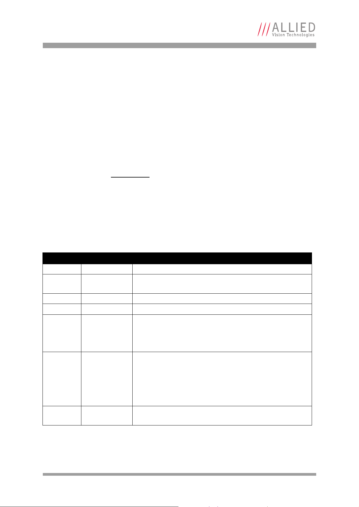
0%
10%
20%
30%
40%
50%
60%
400 500 600 700 800 900 1000
Quantum Efficiency
Wavelength [nm]
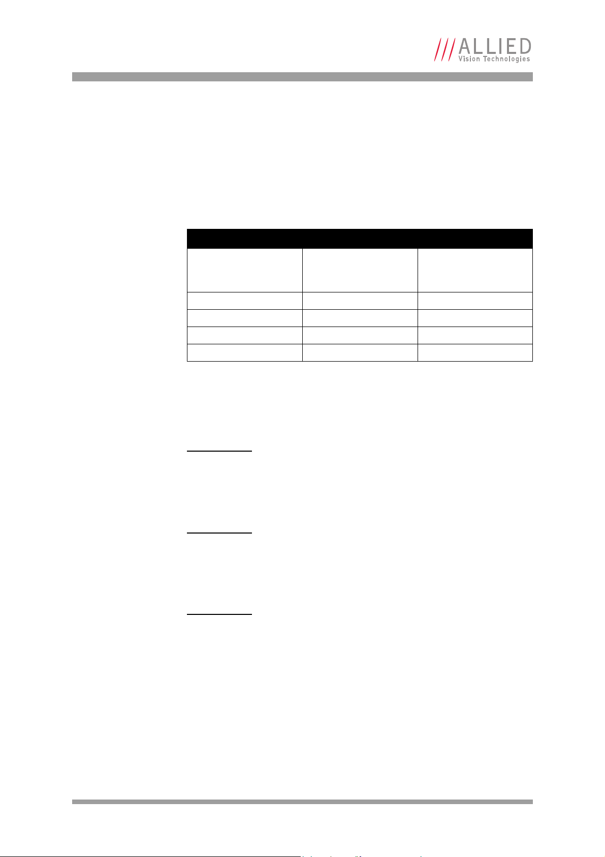
0%
10%
20%
30%
40%
50%
60%
400 450 500 550 600 650 700
Quantum Efficiency
Wavelength [nm]
Red Green Blue
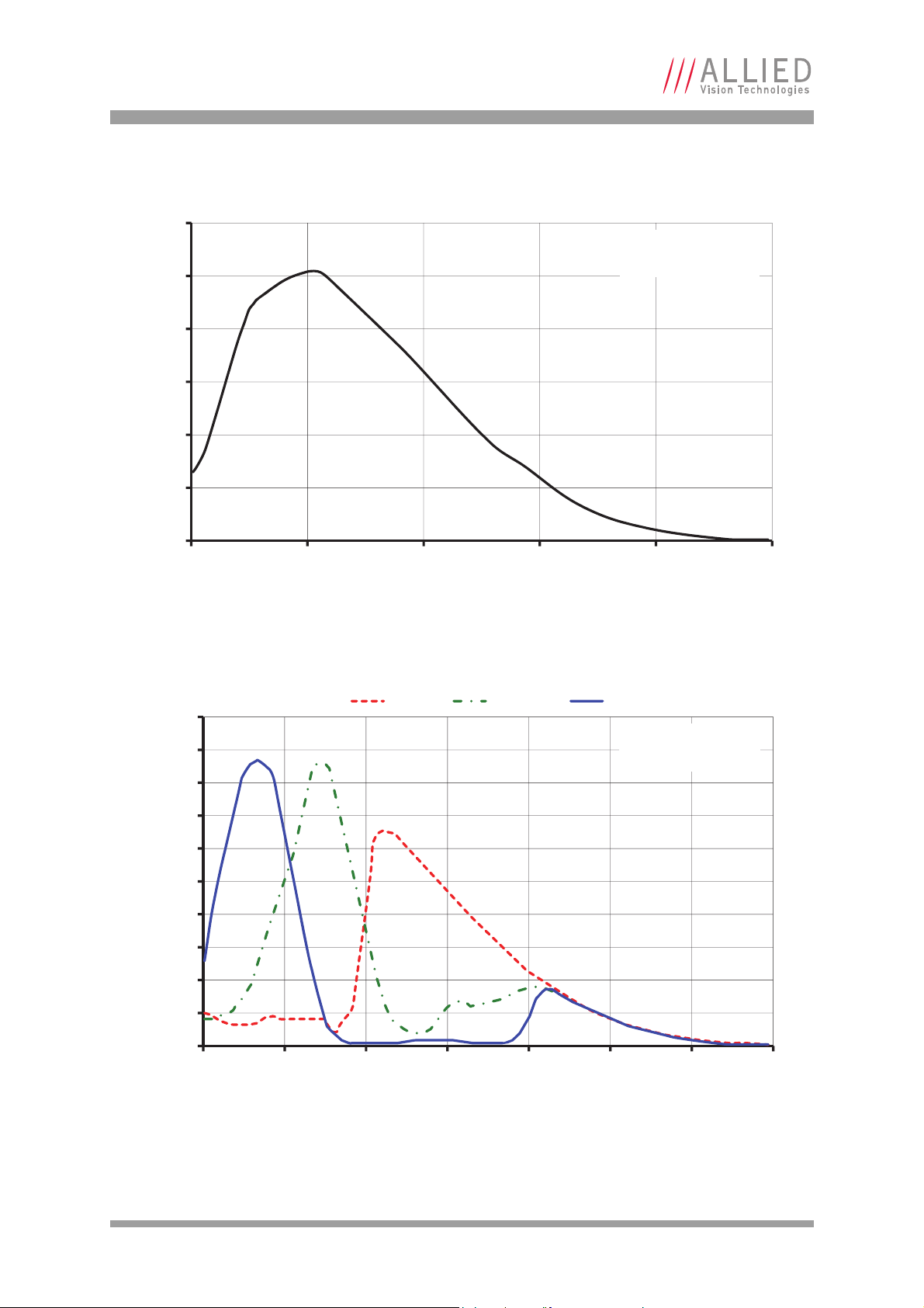
Figure 1: Prosilica GT1290 monochrome spectral response
Figure 2: Prosilica GT1290C color spectral response (without IR cut filter)
AVT Prosilica GT Technical Manual V2.1.0
14
Page 15

Specifications
Prosilica GT1380/1380C
Feature Specification
Resolution 1360 x 1024
Sensor Sony ICX285AL, ICX285AQ for color
Type CCD Progressive
Sensor size Type 2/3
Cell size 6.45 m
Lens mount C (adjustable)
Max frame rate at full resolution 30.5 fps
A/D 14 bit
On-board FIFO 128 MB
Bit depth Monochrome cameras: 14 bit
Color cameras: 12 bit
Mono formats GT1380: Mono8, Mono12Packed, Mono12, Mono14
GT1380C: Mono8
Color formats BayerRG8, BayerRG12, BayerGR12Packed, RGB8Packed, BGR8Packed,
YUV411Packed, YUV422Packed, YUV444Packed
Exposure control 10 µs to 77.3 s; 1 µs increments
Gain control 0 to 34 dB
Horizontal binning 1 to 8 pixels
Vertical binning 1 to 14 rows
TTL I/Os 1 input, 2 outputs
Opto-coupled I/Os 1 input, 2 outputs
RS-232 1 TxD, 1 RxD
Power requirements PoE, or 7–25 VDC external camera power
Power consumption 3.4 W @ 12 VDC
Trigger latency 2.2 µs
Trigger jitter 20 ns
Tpd 30 ns for non-isolated I/O, 70 ns for isolated I/O
Operating temperature -20 to +65 °C ambient temperature (without condensation)
Storage temperature -20 to +70 °C ambient temperature (without condensation)
Operating humidity 20 to 80% non-condensing
Body dimensions (L x W x H) 86 x 53.3 x 33 mm including connectors, w/o tripod and lens
Mass 211 g
Hardware interface standard PoE, IEEE 802.3af 1000BASE-T, 100BASE-TX
Software interface standard GigE Vision Standard 1.2
Regulatory CE, FCC Class A, RoHS (2011/65/EU)
Temperature monitoring Available for both camera and sensor
Resolution: 0.031; Accuracy: ±1°C
Table 4: Prosilica GT1380/1380C camera specifications
AVT Prosilica GT Technical Manual V2.1.0
15
Page 16

Specifications
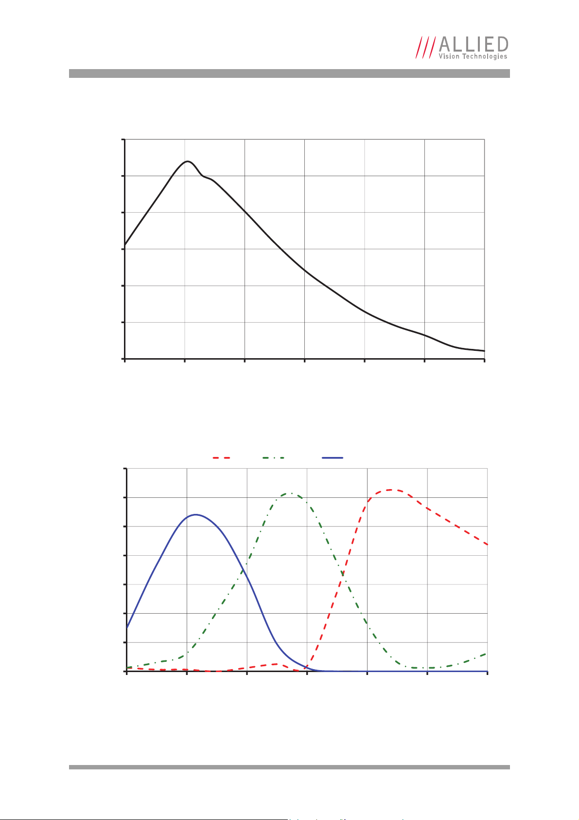
0%
10%
20%
30%
40%
50%
60%
400 500 600 700 800 900 1000
Quantum Efficiency
Wavelength [nm]
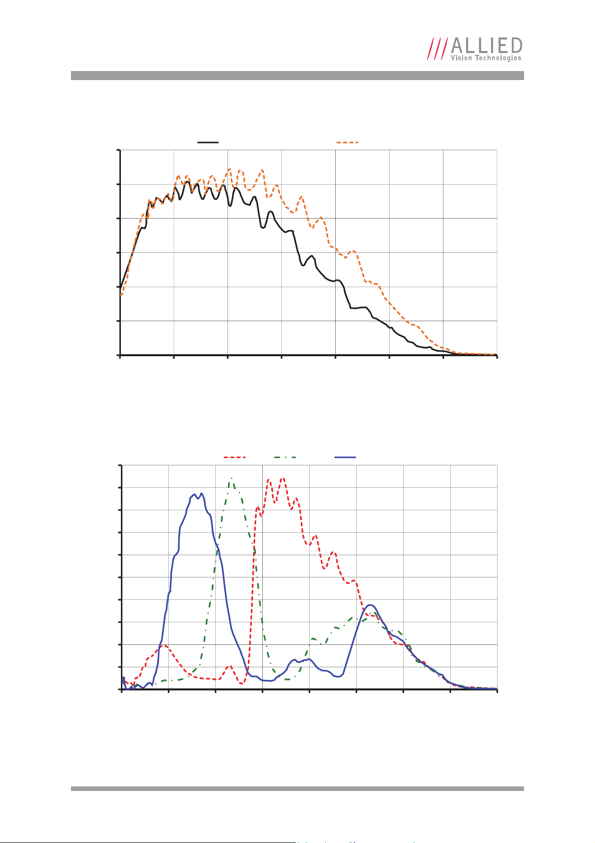
0%
5%
10%
15%
20%
25%
30%
35%
40%
45%
50%
400 450 500 550 600 650 700
Quantum Efficiency
Wavelength [nm]
Red Green Blue
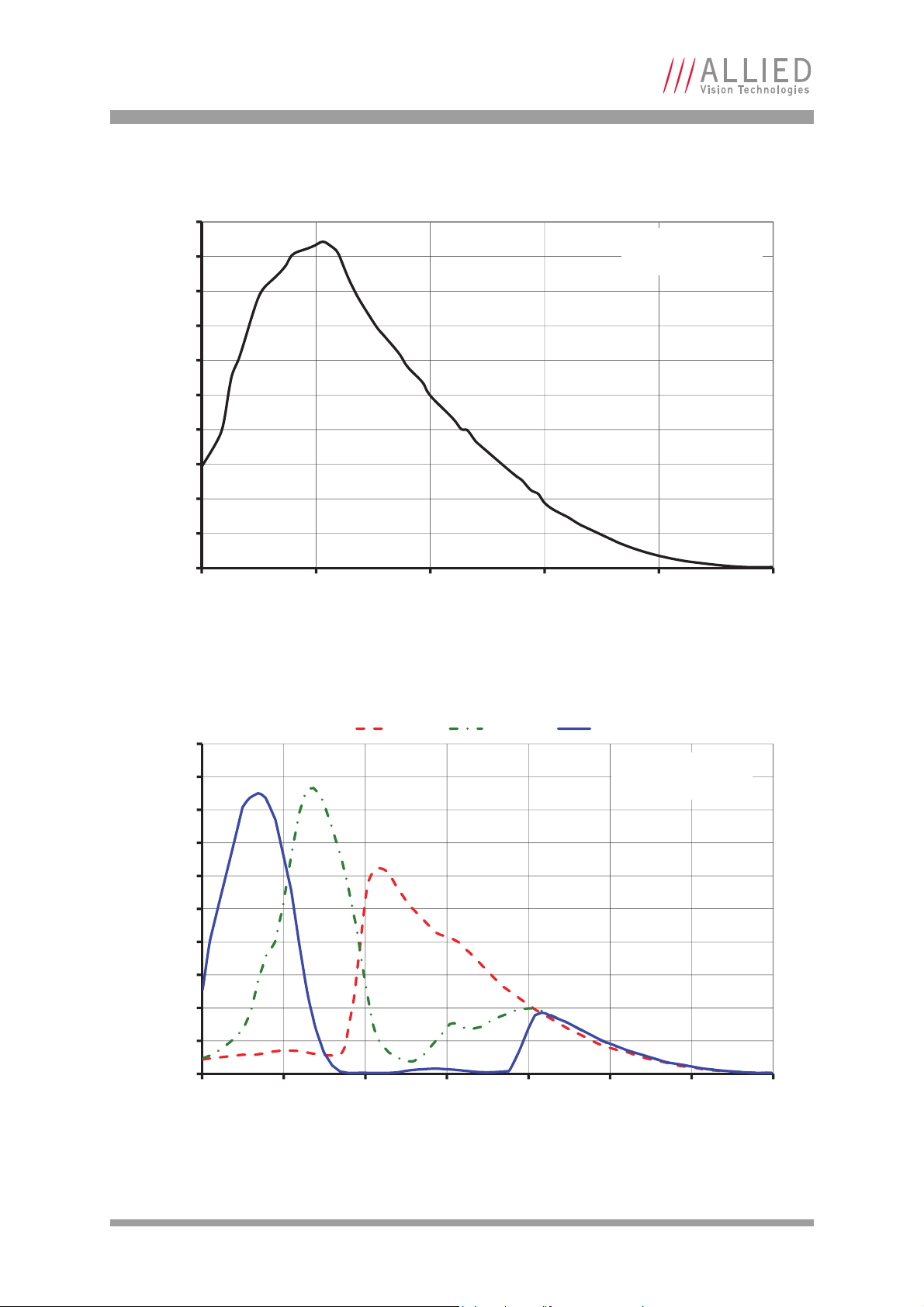
Figure 3: Prosilica GT1380 monochrome spectral response
Figure 4: Prosilica GT1380C color spectral response (without IR cut filter)
AVT Prosilica GT Technical Manual V2.1.0
16
Page 17

Specifications
Prosilica GT1600/1600C
Feature Specification
Resolution 1620 x 1220
Sensor Sony ICX274AL, ICX274AQ for color
Type CCD Progressive
Sensor size Type 1/1.8
Cell size 4.4 m
Lens mount C (adjustable), CS
Max frame rate at full resolution 25.8 fps
A/D 14 bit
On-board FIFO 128 MB, 33 frames at full resolution
Bit depth Monochrome cameras: 14 bit
Color cameras: 12 bit
Mono formats GT1600: Mono8, Mono12Packed, Mono12, Mono14
GT1600C: Mono8
Color formats BayerRG8, BayerRG12, BayerGR12Packed, RGB8Packed, BGR8Packed,
YUV411Packed, YUV422Packed, YUV444Packed
Exposure control 10 µs to 68.7 s; 1 µs increments
Gain control 0 to 26 dB
Horizontal binning 1 to 8 pixels
Vertical binning 1 to 14 rows
TTL I/Os 1 input, 2 outputs
Opto-coupled I/Os 1 input, 2 outputs
RS-232 1 TxD, 1 RxD
Power requirements PoE, or 7–25 VDC external camera power
Power consumption 3.3 W @ 12 VDC
Trigger latency 1.4 µs
Trigger jitter 20 ns
Tpd 30 ns for non-isolated I/O, 70 ns for isolated I/O
Operating temperature -20 to +65 °C ambient temperature (without condensation)
Storage temperature -20 to +70 °C ambient temperature (without condensation)
Operating humidity 20 to 80% non-condensing
Body dimensions (L x W x H) 86 x 53.3 x 33 mm including connectors, w/o tripod and lens
Mass 211 g
Hardware interface standard PoE, IEEE 802.3af 1000BASE-T, 100BASE-TX
Software interface standard GigE Vision Standard 1.2
Regulatory CE, FCC Class A, RoHS (2011/65/EU)
Temperature monitoring Available for both camera and sensor
Resolution: 0.031; Accuracy: ±1°C
Table 5: Prosilica GT1600/1600C camera specifications
AVT Prosilica GT Technical Manual V2.1.0
17
Page 18
Specifications
0%
10%
20%
30%
40%
50%
60%
400 500 600 700 800 900 1000
Quantum Efficiency
Wavelength [nm]
0%
5%
10%
15%
20%
25%
30%
35%
400 450 500 550 600 650 700
Quantum Efficiency
Wavelength [nm]
Red Green Blue
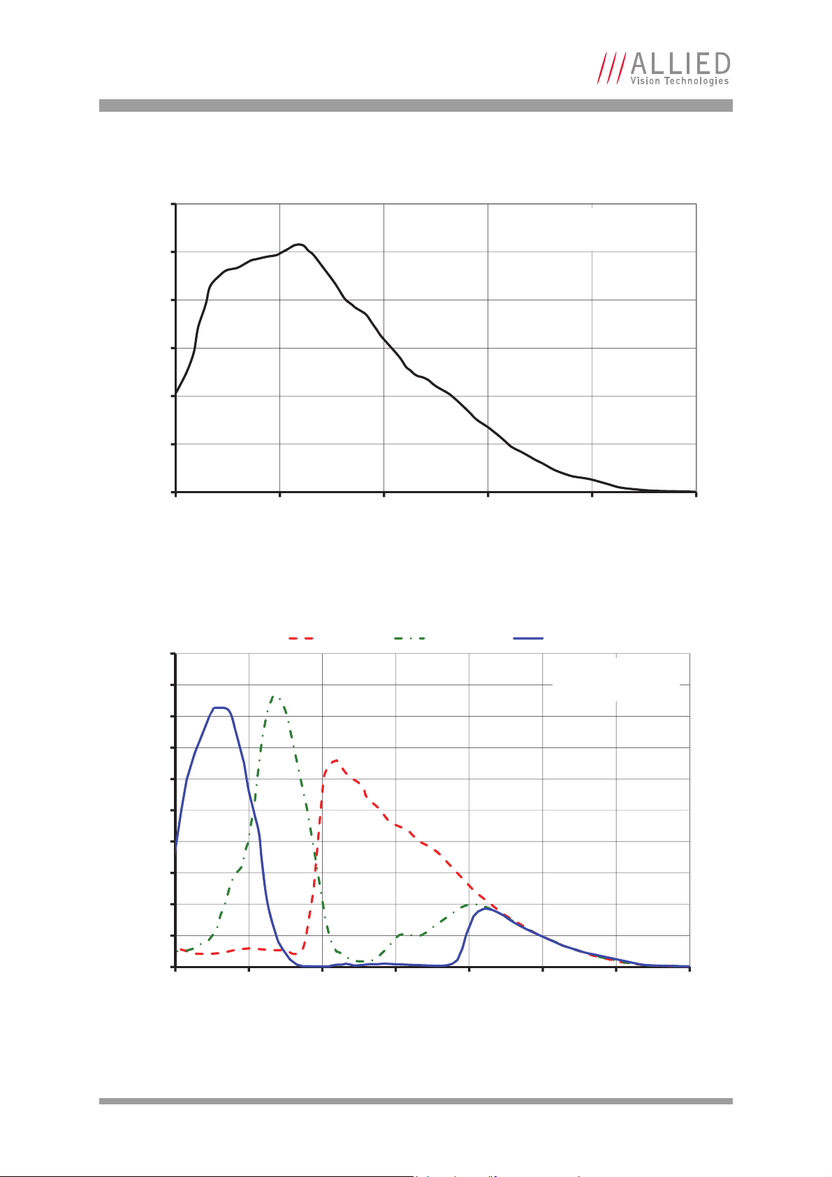
Figure 5: Prosilica GT1600 monochrome spectral response
Figure 6: Prosilica GT1600C color spectral response (without IR cut filter)
AVT Prosilica GT Technical Manual V2.1.0
18
Page 19

Specifications
Prosilica GT1660/1660C
Feature Specification
Resolution 1600 x 1200
Sensor Truesense KAI-02050
Type CCD Progressive
Sensor size Type 2/3
Cell size 5.5 m
Lens mount C (adjustable)
Max frame rate at full resolution 62 fps
A/D 14 bit
On-board FIFO 128 MB, 68 frames at full resolution
Bit depth Monochrome cameras: 14 bit
Color cameras: 12 bit
Mono formats GT1660: Mono8, Mono12Packed, Mono12, Mono14
GT1660C: Mono8
Color formats BayerGR8, BayerGR12, BayerGR12Packed, RGB8Packed, BGR8Packed,
RGBA8Packed, BGRA8Packed, YUV411Packed, YUV422Packed
Exposure control 10 µs to 26.8 s; 1 µs increments
Gain control 0 to 32 dB
Horizontal binning 1 to 8 pixels
Vertical binning 1 to 8 rows
TTL I/Os 1 input, 2 outputs
Opto-coupled I/Os 1 input, 2 outputs
RS-232 1 TxD, 1 RxD
Power requirements PoE, or 7–25 VDC external camera power
Power consumption 5.1 W @ 12 VDC
Trigger latency 2.1 µs
Trigger jitter 20 ns
Tpd 30 ns for non-isolated I/O, 70 ns for isolated I/O
Operating temperature -20 to +60 °C ambient temperature (without condensation)
Storage temperature -20 to +70 °C ambient temperature (without condensation)
Operating humidity 20 to 80% non-condensing
Body dimensions (L x W x H) 92 x 53.3 x 33 mm including connectors, w/o tripod and lens
Mass 224 g
Hardware interface standard PoE, IEEE 802.3af 1000BASE-T, 100BASE-TX
Software interface standard GigE Vision Standard 1.2
Regulatory CE, FCC Class A, RoHS (2011/65/EU)
Temperature monitoring Available for both camera and sensor
Resolution: 0.031; Accuracy: ±1°C
Table 6: Prosilica GT1660/1660C camera specifications
AVT Prosilica GT Technical Manual V2.1.0
19
Page 20

Specifications
0
0.1
0.2
0.3
0.4
0.5
0.6
350 450 550 650 750 850 950 1050 1150
Absolute Quantum Efficiency
Wavelength [nm]
Measured with AR
coated cover glass
0
0.05
0.1
0.15
0.2
0.25
0.3
0.35
0.4
0.45
0.5
400 500 600 700 800 900 1000 1100
Absolute Quantum Efficiency
Wavelength [nm]
Measured with AR
coated cover glass
Red Green Blue
Figure 7: Prosilica GT1660 monochrome spectral response
Figure 8: Prosilica GT1660C color spectral response (without IR cut filter)
AVT Prosilica GT Technical Manual V2.1.0
20
Page 21

Specifications
Prosilica GT1910/1910C
Feature Specification
Resolution 1920 x 1080
Sensor Truesense KAI-02150
Type CCD Progressive
Sensor size Type 2/3
Cell size 5.5 m
Lens mount C (adjustable)
Max frame rate at full resolution 57.5 fps
A/D 14 bit
On-board FIFO 128 MB, 63 frames at full resolution
Bit depth Monochrome cameras: 14 bit
Color cameras: 12 bit
Mono formats GT1910: Mono8, Mono12Packed, Mono12, Mono14
GT1910C: Mono8
Color formats BayerGR8, BayerGR12, BayerGR12Packed, RGB8Packed, BGR8Packed,
RGBA8Packed, BGRA8Packed, YUV411Packed, YUV422Packed
Exposure control 10 µs to 26.8 s; 1 µs increments
Gain control 0 to 32 dB
Horizontal binning 1 to 8 pixels
Vertical binning 1 to 8 rows
TTL I/Os 1 input, 2 outputs
Opto-coupled I/Os 1 input, 2 outputs
RS-232 1 TxD, 1 RxD
Power requirements PoE, or 7–25 VDC external camera power
Power consumption 5.1 W @ 12 VDC
Trigger latency 2.2 µs
Trigger jitter 20 ns
Tpd 30 ns for non-isolated I/O, 70 ns for isolated I/O
Operating temperature -20 to +60 °C ambient temperature (without condensation)
Storage temperature -20 to +70 °C ambient temperature (without condensation)
Operating humidity 20 to 80% non-condensing
Body dimensions (L x W x H) 92 x 53.3 x 33 mm including connectors, w/o tripod and lens
Mass 224 g
Hardware interface standard PoE, IEEE 802.3af 1000BASE-T, 100BASE-TX
Software interface standard GigE Vision Standard 1.2
Regulatory CE, FCC Class A, RoHS (2011/65/EU)
Temperature monitoring Available for both camera and sensor
Resolution: 0.031; Accuracy: ±1°C
Table 7: Prosilica GT1910/1910C camera specifications
AVT Prosilica GT Technical Manual V2.1.0
21
Page 22

Specifications
0%
5%
10%
15%
20%
25%
30%
35%
40%
45%
50%
350 450 550 650 750 850 950 1050
Quantum Efficiency
Wavelength [nm]
Measured with AR
coated cover glass
0%
5%
10%
15%
20%
25%
30%
35%
40%
375 475 575 675 775 875 975 1075
Quantum Efficiency
Wavelength [nm]
Measured with clear
cover glass
Red Green Blue
Figure 9: Prosilica GT1910 monochrome spectral response
Figure 10: Prosilica GT1910C color spectral response (without IR cut filter)
AVT Prosilica GT Technical Manual V2.1.0
22
Page 23

Specifications
Prosilica GT1920/1920C
Feature Specification
Resolution 1936 x 1456
Sensor Sony ICX674
Type CCD Progressive
Sensor size Type 2/3
Cell size 4.54 m
Lens mount C (adjustable)
Max frame rate at full resolution 40.7 fps
A/D 14 bit
On-board FIFO 128 MB
Bit depth Monochrome cameras: 14 bit
Color cameras: 12 bit
Mono formats GT1920: Mono8, Mono12Packed, Mono12, Mono14
GT1920C: Mono8
Color formats BayerGR8, BayerGR12, BayerGR12Packed, RGB8Packed, BGR8Packed,
RGBA8Packed, BGRA8Packed, YUV411Packed, YUV422Packed
Exposure control 10 µs to 26.8 s; 1 µs increments
Gain control 0 to 33 dB
Horizontal binning 1 to 8 pixels
Vertical binning 1 to 8 rows
TTL I/Os 1 input, 2 outputs
Opto-coupled I/Os 1 input, 2 outputs
RS-232 1 TxD, 1 RxD
Power requirements PoE, or 7–25 VDC external camera power
Power consumption 4.9 W @ 12 VDC
Trigger latency 2 µs
Trigger jitter 20 ns
Tpd 30 ns for non-isolated I/O, 70 ns for isolated I/O
Operating temperature -20 to +60 °C ambient temperature (without condensation)
Storage temperature -20 to +70 °C ambient temperature (without condensation)
Operating humidity 20 to 80% non-condensing
Body dimensions (L x W x H) 92 x 53.3 x 33 mm including connectors, w/o tripod and lens
Mass 224 g
Hardware interface standard PoE, IEEE 802.3af 1000BASE-T, 100BASE-TX
Software interface standard GigE Vision Standard 1.2
Regulatory CE, FCC Class A, RoHS (2011/65/EU)
Temperature monitoring Available for both camera and sensor
Resolution: 0.031; Accuracy: ±1°C
Table 8: Prosilica GT1920/1920C camera specifications
AVT Prosilica GT Technical Manual V2.1.0
23
Page 24

Specifications
0%
10%
20%
30%
40%
50%
60%
70%
400 500 600 700 800 900 1000
Quantum Efficiency
Wavelength [nm]
0%
10%
20%
30%
40%
50%
60%
400 450 500 550 600 650 700
Quantum Efficiency
Wavelength [nm]
Red Green Blue
Figure 11: Prosilica GT1920 monochrome spectral response
Figure 12: Prosilica GT1920C color spectral response (without IR cut filter)
AVT Prosilica GT Technical Manual V2.1.0
24
Page 25

Specifications
Prosilica GT2000 / 2000C / 2000 NIR
Feature Specification
Resolution 2048 x 1088
Sensor CMOSIS CMV2000
Type CMOS
Sensor size Type 2/3
Cell size 5.5 m
Lens mount / Lens C (adjustable) / 1 inch format lens recommended
Max frame rate at full resolution 53.7 fps @ 124 MB/s; 60.1 burst mode*
A/D 12 bit
On-board FIFO 128 MB, 29 frames at full resolution
Bit depth 8/12
Mono formats GT2000 / GT2000 NIR: Mono8, Mono12Packed, Mono12
GT2000C: Mono8
Color formats BayerGB8, BayerGB12, BayerGB12Packed, RGB8Packed, BGR8Packed,
RGBA8Packed, BGRA8Packed, YUV411Packed, YUV422Packed, YUV444Packed
Exposure control 1 µs to 126.2 s; 1 µs increments
Gain control 0 to 29 dB
Horizontal binning N/A
Vertical binning N/A
TTL I/Os 1 input, 2 outputs
Opto-coupled I/Os 1 input, 2 outputs
RS-232 1 TxD, 1 RxD
Power requirements PoE, or 7–25 VDC external camera power
Power consumption 3.4 W @ 12 VDC
Trigger latency 700 ns
Trigger jitter 20 ns
Tpd 30 ns for non-isolated I/O, 70 ns for isolated I/O
Operating temperature -20 to +65 °C ambient temperature (without condensation)
Storage temperature -20 to +70 °C ambient temperature (without condensation)
Operating humidity 20 to 80% non-condensing
Body dimensions (L x W x H) 86 x 53.3 x 33 mm including connectors, w/o tripod and lens
Mass 210 g
Hardware interface standard PoE, IEEE 802.3af 1000BASE-T, 100BASE-TX
Software interface standard GigE Vision Standard 1.2
Regulatory CE, FCC Class A, RoHS (2011/65/EU)
Temperature monitoring Available for camera
Resolution: 0.031; Accuracy: ±1°C
*See StreamFrameRateConstrain in AVT GigE Camera and Driver Attributes document.
Table 9: Prosilica GT2000 / 2000C / 2000 NIR camera specifications
AVT Prosilica GT Technical Manual V2.1.0
25
Page 26
Specifications
0
10
20
30
40
50
60
400 500 600 700 800 900 1000 1100
Quantum Efficiency [%]
Wavelength [nm]
GT2000 GT2000 NIR
0
5
10
15
20
25
30
35
40
45
50
300 400 500 600 700 800 900 1000 1100
Quantum Efficiency [%]
Wavelength [nm]
Red Green Blue
Figure 13: Prosilica GT2000 / 2000 NIR monochrome spectral response
Figure 14: Prosilica GT2000C color spectral response (without IR cut filter)
AVT Prosilica GT Technical Manual V2.1.0
26
Page 27

Specifications
Prosilica GT2050 / 2050C / 2050 NIR
Feature Specification
Resolution 2048 x 2048
Sensor CMOSIS CMV4000
Type CMOS
Sensor size Type 1
Cell size 5.5 m
Lens mount C (adjustable)
Max frame rate at full resolution 28.6 fps @ 124 MB/s; 32.0 burst mode*
A/D 12 bit
On-board FIFO 128 MB, 15 frames at full resolution
Bit depth 8/12
Mono formats GT2050 / GT2050 NIR: Mono8, Mono12Packed, Mono12
GT2050C: Mono8
Color formats BayerGB8, BayerGB12, BayerGB12Packed, RGB8Packed, BGR8Packed,
RGBA8Packed, BGRA8Packed, YUV411Packed, YUV422Packed, YUV444Packed
Exposure control 1 µs to 126.2 s; 1 µs increments
Gain control 0 to 24 dB
Horizontal binning N/A
Vertical binning N/A
TTL I/Os 1 input, 2 outputs
Opto-coupled I/Os 1 input, 2 outputs
RS-232 1 TxD, 1 RxD
Power requirements PoE, or 7–25 VDC external camera power
Power consumption 3.5 W @ 12 VDC
Trigger latency 700 ns
Trigger jitter 20 ns
Tpd 30 ns for non-isolated I/O, 70 ns for isolated I/O
Operating temperature -20 to +65 °C ambient temperature (without condensation)
Storage temperature -20 to +70 °C ambient temperature (without condensation)
Operating humidity 20 to 80% non-condensing
Body dimensions (L x W x H) 86 x 53.3 x 33 mm including connectors, w/o tripod and lens
Mass 210 g
Hardware interface standard PoE, IEEE 802.3af 1000BASE-T, 100BASE-TX
Software interface standard GigE Vision Standard 1.2
Regulatory CE, FCC Class A, RoHS (2011/65/EU)
Temperature monitoring Available for camera
Resolution: 0.031; Accuracy: ±1°C
*See StreamFrameRateConstrain in AVT GigE Camera and Driver Attributes document.
Table 10: Prosilica GT2050 / 2050C / 2050 NIR camera specifications
AVT Prosilica GT Technical Manual V2.1.0
27
Page 28

Specifications
0
10
20
30
40
50
60
400 500 600 700 800 900 1000 1100
Quantum Efficiency [%]
Wavelength [nm]
GT2050 GT2050 NIR
0
5
10
15
20
25
30
35
40
45
50
300 400 500 600 700 800 900 1000 1100
Quantum Efficiency [%]
Wavelength [nm]
Red Green Blue
Figure 15: Prosilica GT2050 / 2050 NIR monochrome spectral response
Figure 16: Prosilica GT2050C color spectral response (without IR cut filter)
AVT Prosilica GT Technical Manual V2.1.0
28
Page 29

Specifications
Prosilica GT2300/2300C
Feature Specification
Resolution 2336 x 1752
Sensor Truesense KAI-04050
Type CCD Progressive
Sensor size Type 1
Cell size 5.5 m
Lens mount C (adjustable)
Max frame rate at full resolution 29.3 fps
A/D 14 bit
On-board FIFO 128 MB
Bit depth Monochrome cameras: 14 bit Color
Color cameras: 12 bit
Mono formats GT2300: Mono8, Mono12Packed, Mono12, Mono14
GT2300C: Mono8
Color formats BayerGR8, BayerGR12, BayerGR12Packed, RGB8Packed, BGR8Packed,
RGBA8Packed, BGRA8Packed, YUV411Packed, YUV422Packed
Exposure control 10 µs to 26.8 s; 1 µs increments
Gain control 0 to 32 dB
Horizontal binning 1 to 8 pixels
Vertical binning 1 to 8 rows
TTL I/Os 1 input, 2 outputs
Opto-coupled I/Os 1 input, 2 outputs
RS-232 1 TxD, 1 RxD
Power requirements PoE, or 7–25 VDC external camera power
Power consumption 4.9 W @ 12 VDC
Trigger latency 2.2 µs
Trigger jitter 20 ns
Tpd 30 ns for non-isolated I/O, 70 ns for isolated I/O
Operating temperature -20 to +60 °C ambient temperature (without condensation)
Storage temperature -20 to +70 °C ambient temperature (without condensation)
Operating humidity 20 to 80% non-condensing
Body dimensions (L x W x H) 92 x 53.3 x 33 mm including connectors, w/o tripod and lens
Mass 229 g
Hardware interface standard PoE, IEEE 802.3af 1000BASE-T, 100BASE-TX
Software interface standard GigE Vision Standard 1.2
Regulatory CE, FCC Class A, RoHS (2011/65/EU)
Temperature monitoring Available for both camera and sensor
Resolution: 0.031; Accuracy: ±1°C
Table 11: Prosilica GT2300/2300C camera specifications
AVT Prosilica GT Technical Manual V2.1.0
29
Page 30
Specifications
0
0.1
0.2
0.3
0.4
0.5
0.6
350 500 650 800 950 1100
Absolute Quantum Efficiency
Wavelength [nm]
Measured with AR
coated cover glass
0
0.05
0.1
0.15
0.2
0.25
0.3
0.35
0.4
0.45
0.5
400 500 600 700 800 900 1000 1100
Absolute Quantum Efficiency
Wavelength [nm]
Measured with AR
coated cover glass
Red Green Blue
Figure 17: Prosilica GT2300 monochrome spectral response
Figure 18: Prosilica GT2300C color spectral response (without IR cut filter)
AVT Prosilica GT Technical Manual V2.1.0
30
Page 31

Specifications
Prosilica GT2450/2450C
Feature Specification
Resolution 2448 x 2050
Sensor Sony ICX625ALA. Sony ICX625AQA for color
Type CCD Progressive
Sensor size Type 2/3
Cell size 3.45 m
Lens mount C (adjustable)
Max frame rate at full resolution 15 fps
A/D 14 bit
On-board FIFO 128 MB, 13 frames at full resolution
Bit depth Monochrome cameras: 14 bit
Color cameras: 12 bit
Mono formats GT2450: Mono8, Mono12Packed, Mono12, Mono14
GT2450C: Mono8
Color formats BayerRG8, BayerRG12, BayerGR12Packed, RGB8Packed, BGR8Packed,
YUV411Packed, YUV422Packed, YUV444Packed
Exposure control 25 µs to 42.9 s; 1 µs increments
Gain control 0 to 30 dB
Horizontal binning 1 to 8 pixels
Vertical binning 1 to 14 rows
TTL I/Os 1 input, 2 outputs
Opto-coupled I/Os 1 input, 2 outputs
RS-232 1 TxD, 1 RxD
Power requirements PoE, or 7–25 VDC external camera power
Power consumption 3.8 W @ 12 VDC
Trigger latency 1.1 µs
Trigger jitter 20 ns
Tpd 30 ns for non-isolated I/O, 70 ns for isolated I/O
Operating temperature -20 to +65 °C ambient temperature (without condensation)
Storage temperature -20 to +70 °C ambient temperature (without condensation)
Operating humidity 20 to 80% non-condensing
Body dimensions (L x W x H) 86 x 53.3 x 33 mm including connectors, w/o tripod and lens
Mass 211 g
Hardware interface standard PoE, IEEE 802.3af 1000BASE-T, 100BASE-TX
Software interface standard GigE Vision Standard 1.2
Regulatory CE, FCC Class A, RoHS (2011/65/EU)
Temperature monitoring Available for both camera and sensor
Resolution: 0.031; Accuracy: ±1°C
Table 12: Prosilica GT2450/2450C camera specifications
AVT Prosilica GT Technical Manual V2.1.0
31
Page 32

Specifications
0%
10%
20%
30%
40%
50%
60%
400 500 600 700 800 900 1000
Quantum Efficiency
Wavelength [nm]
0%
5%
10%
15%
20%
25%
30%
35%
40%
45%
400 450 500 550 600 650 700
Quantum Efficiency
Wavelength [nm]
Red Green Blue
Figure 19: Prosilica GT2450 monochrome spectral response
Figure 20: Prosilica GT2450C color spectral response (without IR cut filter)
AVT Prosilica GT Technical Manual V2.1.0
32
Page 33

Specifications
Prosilica GT2750/2750C
Feature Specification
Resolution 2750 x 2200
Sensor Sony ICX694 ALG. Sony ICX694 AQG for color
Type CCD Progressive
Sensor size Type 1
Cell size 4.54 m
Lens mount C (adjustable)
Max frame rate at full resolution 19.8 fps
A/D 14 bit
On-board FIFO 128 MB, 21 frames at full resolution
Bit depth Monochrome cameras: 14 bit
Color cameras: 12 bit
Mono formats GT2750: Mono8, Mono12Packed, Mono12, Mono14
GT2750C: Mono8
Color formats BayerGR8, BayerGR12, BayerGR12Packed, RGB8Packed, BGR8Packed,
RGBA8Packed, BGRA8Packed, YUV411Packed, YUV422Packed
Exposure control 10 µs to 26.8 s; 1 µs increments
Gain control 0 to 32 dB
Horizontal binning 1 to 8 pixels
Vertical binning 1 to 8 rows
TTL I/Os 1 input, 2 outputs
Opto-coupled I/Os 1 input, 2 outputs
RS-232 1 TxD, 1 RxD
Power requirements PoE, or 7–25 VDC external camera power
Power consumption 5.4 W @ 12 VDC
Trigger latency 2.2 µs
Trigger jitter 20 ns
Tpd 30 ns for non-isolated I/O, 70 ns for isolated I/O
Operating temperature -20 to +60 °C ambient temperature (without condensation)
Storage temperature -20 to +70 °C ambient temperature (without condensation)
Operating humidity 20 to 80% non-condensing
Body dimensions (L x W x H) 92 x 53.3 x 33 mm including connectors, w/o tripod and lens
Mass 224 g
Hardware interface standard PoE, IEEE 802.3af 1000BASE-T, 100BASE-TX
Software interface standard GigE Vision Standard 1.2
Regulatory CE, FCC Class A, RoHS (2011/65/EU)
Temperature monitoring Available for both camera and sensor
Resolution: 0.031; Accuracy: ±1°C
Table 13: Prosilica GT2750/2750C camera specifications
AVT Prosilica GT Technical Manual V2.1.0
33
Page 34

Specifications
0%
10%
20%
30%
40%
50%
60%
70%
400 500 600 700 800 900 1000
Quantum Efficiency
Wavelength [nm]
0%
10%
20%
30%
40%
50%
60%
70%
80%
400 450 500 550 600 650 700
Quantum Efficiency
Wavelength [nm]
Red Green Blue
Figure 21: Prosilica GT2750 monochrome spectral response
Figure 22: Prosilica GT2750C color spectral response (without IR cut filter)
AVT Prosilica GT Technical Manual V2.1.0
34
Page 35

Specifications
Prosilica GT3300/3300C
Feature Specification
Resolution 3296 x 2472
Sensor Truesense KAI-8050
Type CCD Progressive
Sensor size Type 4/3
Cell size 5.5 m
Lens mount F
Max frame rate at full resolution 14.7 fps
A/D 14 bit
On-board FIFO 128 MB, 16 frames at full resolution
Bit depth Monochrome cameras: 14 bit
Color cameras: 12 bit
Mono formats GT3300: Mono8, Mono12Packed, Mono12, Mono14
GT3300C: Mono8
Color formats BayerGR8, BayerGR12, BayerGR12Packed, RGB8Packed, BGR8Packed,
RGBA8Packed, BGRA8Packed, YUV411Packed, YUV422Packed
Exposure control 10 µs to 26.8 s; 1 µs increments
Gain control 0 to 32 dB
Horizontal binning 1 to 8 pixels
Vertical binning 1 to 8 rows
TTL I/Os 1 input, 2 outputs
Opto-coupled I/Os 1 input, 2 outputs
RS-232 1 TxD, 1 RxD
Power requirements PoE, or 7–25 VDC external camera power
Power consumption 5.6 W @ 12 VDC
Trigger latency 2.2 µs
Trigger jitter 20 ns
Tpd 30 ns for non-isolated I/O, 70 ns for isolated I/O
Operating temperature -20 to +60 °C ambient temperature (without condensation)
Storage temperature -20 to +70 °C ambient temperature (without condensation)
Operating humidity 20 to 80% non-condensing
Body dimensions (L x W x H) 121 x 59.7 x 59.7 mm including connectors, w/o tripod and lens
Mass 314 g
Hardware interface standard PoE, IEEE 802.3af 1000BASE-T, 100BASE-TX
Software interface standard GigE Vision Standard 1.2
Regulatory CE, FCC Class A, RoHS (2011/65/EU)
Temperature monitoring Available for both camera and sensor
Resolution: 0.031; Accuracy: ±1°C
Table 14: Prosilica GT3300/3300C camera specifications
AVT Prosilica GT Technical Manual V2.1.0
35
Page 36

Specifications
0
0.1
0.2
0.3
0.4
0.5
0.6
350 500 650 800 950 1100
Absolute Quantum Efficiency
Wavelength [nm]
Measured with AR
coated cover glass
0
0.05
0.1
0.15
0.2
0.25
0.3
0.35
0.4
0.45
0.5
400 500 600 700 800 900 1000 1100
Absolute Quantum Efficiency
Wavelength [nm]
Measured with AR
coated cover glass
Red Green Blue
Figure 23: Prosilica GT3300 monochrome spectral response
Figure 24: Prosilica GT3300C color spectral response (without IR cut filter)
AVT Prosilica GT Technical Manual V2.1.0
36
Page 37

Specifications
Prosilica GT3400/3400C
Feature Specification
Resolution 3384 x 2704
Sensor Sony ICX814
Type CCD Progressive
Sensor size Type 1
Cell size 3.69 m
Lens mount C (adjustable)
Max frame rate at full resolution 12.7 fps @ 124 MB/s; 14 burst mode*
A/D 14 bit
On-board FIFO 128 MB
Bit depth Monochrome cameras: 14 bit; Color cameras: 12 bit
Mono formats GT3400: Mono8, Mono12Packed, Mono12, Mono14
GT3400C: Mono8
Color formats BayerRG8, BayerRG12, BayerRG12Packed, RGB8Packed, BGR8Packed,
RGBA8Packed, BGRA8Packed, YUV411Packed, YUV422Packed
Exposure control 10 µs to 26.8 s; 1 µs increments
Gain control 0 to 31 dB
Horizontal binning 1 to 8 pixels
Vertical binning 1 to 8 rows
TTL I/Os 1 input, 2 outputs
Opto-coupled I/Os 1 input, 2 outputs
RS-232 1 TxD, 1 RxD
Power requirements PoE, or 7–25 VDC external camera power
Power consumption 5.4 W @ 12 VDC
Trigger latency 2.5 µs
Trigger jitter 20 ns
Tpd 30 ns for non-isolated I/O, 70 ns for isolated I/O
Operating temperature -20 to +60 °C ambient temperature (without condensation)
Storage temperature -20 to +70 °C ambient temperature (without condensation)
Operating humidity 20 to 80% non-condensing
Body dimensions (L x W x H) 92 x 53.3 x 33 mm including connectors, w/o tripod and lens
Mass 224 g
Hardware interface standard PoE, IEEE 802.3af 1000BASE-T, 100BASE-TX
Software interface standard GigE Vision Standard 1.2
Regulatory CE, FCC Class A, RoHS (2011/65/EU)
Temperature monitoring Available for both camera and sensor
Resolution: 0.031; Accuracy: ±1°C
*See StreamFrameRateConstrain in AVT GigE Camera and Driver Attributes document.
Table 15: Prosilica GT3400/3400C camera specifications
AVT Prosilica GT Technical Manual V2.1.0
37
Page 38

Specifications
0%
10%
20%
30%
40%
50%
60%
70%
400 500 600 700 800 900 1000
Quantum Efficiency
Wavelength [nm]
0%
10%
20%
30%
40%
50%
400 450 500 550 600 650 700
Quantum Efficiency
Wavelength [nm]
Red Green Blue
Figure 25: Prosilica GT3400 monochrome spectral response
Figure 26: Prosilica GT3400C color spectral response (without IR cut filter)
AVT Prosilica GT Technical Manual V2.1.0
38
Page 39

Specifications
Prosilica GT4100/4100C - Preliminary
Feature Specification
Resolution 4096 x 3072
Sensor CMOSIS CMV12000
Type CMOS
Sensor size APS-C (28 mm diagonal)
Cell size 5.5 m
Lens mount F (M58 optional)
Max frame rate at full resolution 4 fps
A/D 12 bit
On-board FIFO 128 MB
Bit depth 8/12
Mono formats GT4100: Mono8, Mono12Packed, Mono12
GT4100C: Mono8
Color formats BayerGB8, BayerGB12, BayerGB12Packed, RGB8Packed, BGR8Packed,
YUV411Packed, YUV422Packed, YUV422Packed
Exposure control 1 µs to 171.7 s; 1 µs increments
Gain control 0 to 26 dB
Horizontal binning N/A
Vertical binning N/A
TTL I/Os 1 input, 2 outputs
Opto-coupled I/Os 1 input, 2 outputs
RS-232 1 TxD, 1 RxD
Power requirements PoE, or 7–25 VDC external camera power
Power consumption 3.85 W @ 12 VDC
Trigger latency 2.5 µs
Trigger jitter 20 ns
Tpd 30 ns for non-isolated I/O, 70 ns for isolated I/O
Operating temperature -20 to +60 °C ambient temperature (without condensation)
Storage temperature -20 to +70 °C ambient temperature (without condensation)
Operating humidity 20 to 80% non-condensing
Body dimensions (L x W x H) 96 x 66 x 53.3 mm including connectors, w/o tripod and lens
Mass 372 g
Hardware interface standard PoE, IEEE 802.3af 1000BASE-T, 100BASE-TX
Software interface standard GigE Vision Standard 1.2
Regulatory CE, FCC Class A, RoHS (2011/65/EU)
Temperature monitoring Available for camera
Resolution: 0.031; Accuracy: ±1°C
TBD: Monochrome and color spectral response for Prosilica GT4100/4100C
Table 16: Prosilica GT4100/4100C camera specifications
AVT Prosilica GT Technical Manual V2.1.0
39
Page 40

Specifications
Prosilica GT4905/4905C
Feature Specification
Resolution 4896 x 3264
Sensor Truesense KAI-16050
Type CCD Progressive
Sensor size APS-H (32.36 mm diagonal)
Cell size 5.5 m
Lens mount F (M58 optional)
Max frame rate at full resolution 7.5 fps @ 124 MB/s; 8.5 burst mode*
A/D 14 bit
On-board FIFO 128 MB
Bit depth Monochrome cameras: 14 bit; Color cameras: 12 bit
Mono formats GT4905: Mono8, Mono12Packed, Mono12, Mono14
GT4905C: Mono8
Color formats BayerGR8, BayerGR12, BayerGR12Packed, RGB8Packed, BGR8Packed,
RGBA8Packed, BGRA8Packed, YUV411Packed, YUV422Packed
Exposure control 15 µs to 26.8 s; 1 µs increments
Gain control 0 to 32 dB
Horizontal binning 1 to 8 pixels
Vertical binning 1 to 8 rows
TTL I/Os 1 input, 2 outputs
Opto-coupled I/Os 1 input, 2 outputs
RS-232 1 TxD, 1 RxD
Power requirements PoE, or 7–25 VDC external camera power
Power consumption 7.3 W @ 12 VDC
Trigger latency 2.5 µs
Trigger jitter 20 ns
Tpd 30 ns for non-isolated I/O, 70 ns for isolated I/O
Operating temperature -20 to +50 °C ambient temperature (without condensation)
Storage temperature -20 to +70 °C ambient temperature (without condensation)
Operating humidity 20 to 80% non-condensing
Body dimensions (L x W x H) 96 x 66 x 53.3 mm including connectors, w/o tripod and lens
Mass 372g
Hardware interface standard PoE, IEEE 802.3af 1000BASE-T, 100BASE-TX
Software interface standard GigE Vision Standard 1.2
Regulatory CE, FCC Class A, RoHS (2011/65/EU)
Temperature monitoring Available for both camera and sensor
Resolution: 0.031; Accuracy: ±1°C
*See StreamFrameRateConstrain in AVT GigE Camera and Driver Attributes document.
Table 17: Prosilica GT4905/4905C camera specifications
AVT Prosilica GT Technical Manual V2.1.0
40
Page 41
Specifications
0
0.05
0.1
0.15
0.2
0.25
0.3
0.35
0.4
0.45
0.5
350 500 650 800 950 1100
Absolute Quantum Efficiency
Wavelength [nm]
Measured with AR
coated cover glass
0
0.05
0.1
0.15
0.2
0.25
0.3
0.35
0.4
0.45
0.5
400 500 600 700 800 900 1000 1100
Absolute Quantum Efficiency
Wavelength [nm]
Measured with AR
coated cover glass
Red Green Blue
Figure 27: Prosilica GT4905 monochrome spectral response
Figure 28: Prosilica GT4905C color spectral response (without IR cut filter)
AVT Prosilica GT Technical Manual V2.1.0
41
Page 42

Specifications
Prosilica GT4907/4907C
Feature Specification
Resolution 4864 x 3232
Sensor Truesense KAI-16070
Type CCD Progressive
Sensor size 35 mm
Cell size 7.4 m
Lens mount F (M58 optional)
Max frame rate at full resolu- 7.6 fps
A/D 14 bit
On-board FIFO 128 MB
Bit depth Monochrome cameras: 14 bit; Color cameras: 12 bit
Mono formats GT4907: Mono8, Mono12Packed, Mono12, Mono14
GT4907C: Mono8
Color formats BayerGR8, BayerGR12, BayerGR12Packed, RGB8Packed, BGR8Packed,
RGBA8Packed, BGRA8Packed, YUV411Packed, YUV422Packed
Exposure control 35 µs to 26.8 s; 1 µs increments
Gain control 0 to 32 dB
Horizontal binning 1 to 8 pixels
Vertical binning 1 to 8 rows
TTL I/Os 1 input, 2 outputs
Opto-coupled I/Os 1 input, 2 outputs
RS-232 1 TxD, 1 RxD
Power requirements PoE, or 7–25 VDC external camera power
Power consumption 7.7 W @ 12 VDC
Trigger latency 2.5 µs
Trigger jitter 20 ns
Tpd 30 ns for non-isolated I/O, 70 ns for isolated I/O
Operating temperature -20 to +50 °C ambient temperature (without condensation)
Storage temperature -20 to +70 °C ambient temperature (without condensation)
Operating humidity 20 to 80% non-condensing
Body dimensions (L x W x H) 96 x 66 x 53.3 mm including connectors, w/o tripod and lens
Mass 372g
Hardware interface standard PoE, IEEE 802.3af 1000BASE-T, 100BASE-TX
Software interface standard GigE Vision Standard 1.2
Regulatory CE, FCC Class A, RoHS (2011/65/EU)
Temperature monitoring Available for both camera and sensor
Resolution: 0.031; Accuracy: ±1°C
Table 18: Prosilica GT4907/4907C camera specifications
AVT Prosilica GT Technical Manual V2.1.0
42
Page 43
Specifications
0
0.1
0.2
0.3
0.4
0.5
0.6
350 500 650 800 950 1100
Absolute Quantum Efficiency
Wavelength [nm]
Measured with AR
coated cover glass
0
0.05
0.1
0.15
0.2
0.25
0.3
0.35
0.4
0.45
0.5
400 500 600 700 800 900 1000 1100
Absolute Quantum Efficiency
Wavelength [nm]
Measured with AR
coated cover glass
Red Green Blue
Figure 29: Prosilica GT4907 monochrome spectral response
Figure 30: Prosilica GT4907C color spectral response (without IR cut filter)
AVT Prosilica GT Technical Manual V2.1.0
43
Page 44

Specifications
Prosilica GT6600/6600C
Feature Specification
Resolution 6576 x 4384
Sensor Truesense KAI-29050
Type CCD Progressive
Sensor size Type 4/3
Cell size 35 mm
Lens mount F (M58 optional)
Max frame rate at full resolution 4 fps
A/D 14 bit
On-board FIFO 128 MB
Bit depth Monochrome cameras: 14 bit
Color cameras: 12 bit
Mono formats GT6600: Mono8, Mono12Packed, Mono12, Mono14
GT6600C: Mono8
Color formats BayerGR8, BayerGR12, BayerGR12Packed, RGB8Packed, BGR8Packed,
RGBA8Packed, BGRA8Packed, YUV411Packed, YUV422Packed
Exposure control 30 µs to 33.5 s; 1 µs increments
Gain control 0 to 32 dB
Horizontal binning 1 to 8 pixels
Vertical binning 1 to 8 rows
TTL I/Os 1 input, 2 outputs
Opto-coupled I/Os 1 input, 2 outputs
RS-232 1 TxD, 1 RxD
Power requirements PoE, or 7–25 VDC external camera power
Power consumption 6.6 W @ 12 VDC
Trigger latency 2.5 µs
Trigger jitter 20 ns
Tpd 30 ns for non-isolated I/O, 70 ns for isolated I/O
Operating temperature -20 to +50 °C ambient temperature (without condensation)
Storage temperature -20 to +70 °C ambient temperature (without condensation)
Operating humidity 20 to 80% non-condensing
Body dimensions (L x W x H) 96 x 66 x 53.3 mm including connectors, w/o tripod and lens
Mass 372 g
Hardware interface standard PoE, IEEE 802.3af 1000BASE-T, 100BASE-TX
Software interface standard GigE Vision Standard 1.2
Regulatory CE, FCC Class A, RoHS (2011/65/EU)
Temperature monitoring Available for both camera and sensor
Resolution: 0.031; Accuracy: ±1°C
Table 19: Prosilica GT6600/6600C camera specifications
AVT Prosilica GT Technical Manual V2.1.0
44
Page 45

Specifications
0
0.1
0.2
0.3
0.4
0.5
350 500 650 800 950 1100
Absolute Quantum Efficiency
Wavelength [nm]
Measured with AR
coated cover glass
0
0.05
0.1
0.15
0.2
0.25
0.3
0.35
0.4
0.45
0.5
400 500 600 700 800 900 1000 1100
Absolute Quantum Efficiency
Wavelength [nm]
Measured with AR
coated cover glass
Red Green Blue
Figure 31: Prosilica GT6600 monochrome spectral response
Figure 32: Prosilica GT6600C color spectral response (without IR cut filter)
AVT Prosilica GT Technical Manual V2.1.0
45
Page 46

Camera attribute highlights
Camera attribute highlights
AVT cameras support a number of standard and extended features. The table
below identifies a selection of interesting capabilities of the Prosilica GT camera
family.
www
Control Description
Gain control Manual and auto
Exposure control Manual and auto
White balance Red and blue channel; manual and auto control
External trigger event
External trigger delay 0– 60* s; 1 µs increments
Fixed rate control 0.001 fps to maximum frame rate
Imaging modes
Sync out modes
Region of interest
Multicast Streaming to multiple computers
Event channel
Chunk data
Color matrix
Gamma, Hue, Saturation Adjust image gamma, hue and saturation
Precision Time Protocol
IEEE1588
Lens control Control P-Iris lenses
*May vary with the camera models
A complete listing of camera controls, including control definitions can be found online:
PvAPI users: AVT GigE Camera and Driver Attributes document
VIMBA users: AVT GigE Camera and Driver Features document
Rising edge, falling edge, any edge, level high,
level low
Free-running, external trigger, fixed rate, software trigger
Trigger ready, trigger input, exposing, readout,
imaging, strobe, GPO
Independent x and y control with 1 pixel resolution
In-camera events including exposure start and
trigger are asynchronously broadcasted to the
host computer
Captured images are bundled with attribute information such as exposure and gain value
Correct color rendering for specific color temperature
Synchronize clocks of multiple cameras using
multicast messaging
Table 20: Prosilica GT camera and driver attribute highlights
AVT Prosilica GT Technical Manual V2.1.0
46
Page 47
Filters
0
10
20
30
40
50
60
70
80
90
100
350 450 550 650 750 850 950
Transmission [%]
Wavelength [nm]
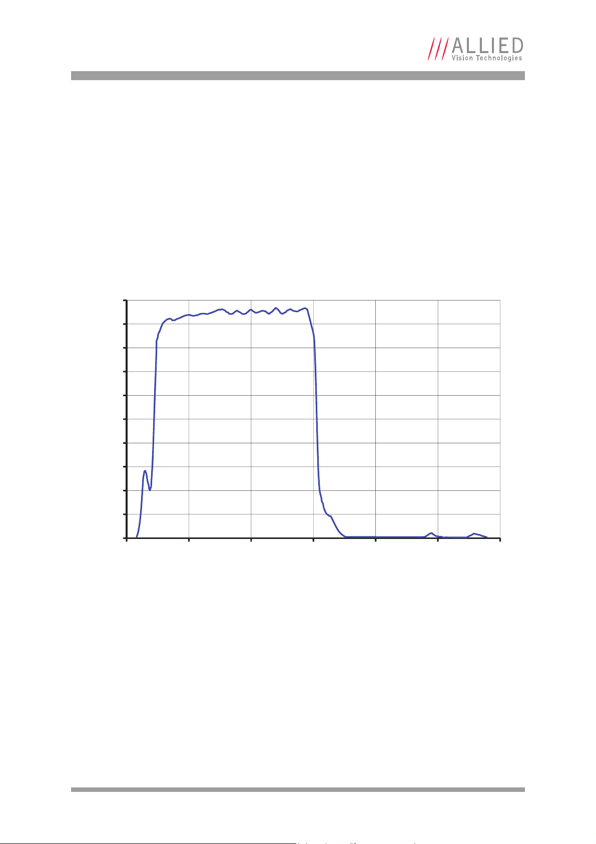
Filters
All Prosilica GT color models are equipped with an infrared block filter (IR filter). This filter is employed to prevent infrared wavelength photons from passing to the sensor. In the absence of IR filter, images are dominated by red and
incapable of being properly color balanced. Monochrome cameras do not
employ an IR filter.
The figure below shows the filter transmission response for the IRC30 filter
employed in the Prosilica GT cameras.
Figure 33: IRC30 filter transmission response
AVT Prosilica GT Technical Manual V2.1.0
47
Page 48
Camera dimensions
70.5
5.1
26.7
26
26
65.2
2.8 2.5
M3x4 (4x)
26 26
2.8
65.2
11.7 Nominal
Precise dimension
is sensor dependent
6.3
M3x4 (4x)
34
38
53.3
16 26 33
31.6
Adjustable
C-Mount
M3x4 (8x)
20
20.6
29.9
19.1
11.4
14
M2x3 (4x)
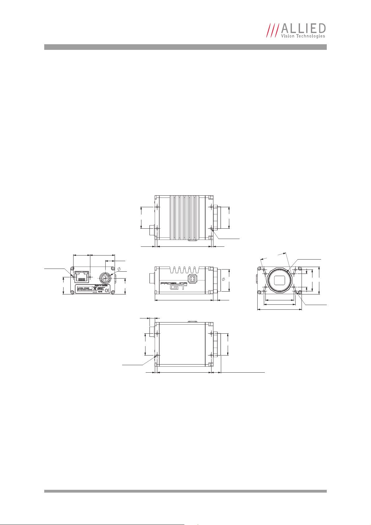
Camera dimensions
The Prosilica GT family supports a range of sensor configurations. To support
this sensor variety three camera body sizes are used:
• Prosilica GT standard
•Prosilica GT long
•Prosilica GT large format
Prosilica GT standard cameras (C-Mount)
Prosilica GT1290, GT1380, GT1600, GT2000, GT2050, GT2450
Figure 34: Mechanical dimensions for C-Mount Prosilica GT standard cameras
AVT Prosilica GT Technical Manual V2.1.0
48
Page 49

Camera dimensions
76.2
5.1
26.7
26
26
70.9
2.8 2.5
M3x4 (4x)
26
26
2.8
70.9
12 Nominal
Precise dimension
is sensor dependent
6.3
M3x4 (4x)
34
38
53.3
16 26 33
31.6
Adjustable
C-Mount
M3x4 (8x)
20
20.6
29.9
19.1
11.4
14
M2x3 (4x)
Prosilica GT long cameras
C-Mount
Prosilica GT1660, GT1910, GT1920, GT2300, GT2750, GT3400
Figure 35: Mechanical dimensions for C-Mount Prosilica GT long cameras
AVT Prosilica GT Technical Manual V2.1.0
49
Page 50

Camera dimensions
76.2 10
28.5*
33
59.7
Adjustable
Nikon F-Mount
20 29.9
20.6
19.1
14
11.4
M2x3 (4x)
2.8
70.9
2.5
26
M3x4 (4x)
70.9
2.8 2.5
6.3
26
53.3
M3x4 (4x)
*Nominal
Precise dimension
is sensor dependent
F-Mount
Prosilica GT3300
Figure 36: Mechanical dimensions for F-Mount GT3300
AVT Prosilica GT Technical Manual V2.1.0
50
Page 51

Camera dimensions
53.3
53.3
9.7
*Nominal
Precise dimension is sensor dependent
26 26
48.3
2.5 2.5
M3x4 (4x) 2 sides
40.1 47.2
52.8
59.9
59.7
M3x4 (8x)
Adjustable
Nikon F-Mount
12.7
20
11.4
13.5
M2x3 (2x)
2.5
48.3
2.5
26
40
27.9
28
1/4-20
Tripod Mount
2 sides
M3x4 (4x) 2 sides
6.3
28
27.9
6 (2x) 2 sides
66
26.8*
Prosilica GT large format cameras
Prosilica GT4100, GT4905, GT4907, GT6600
Figure 37: Mechanical dimensions for F-Mount Prosilica GT large format cameras. M58-Mount dimensions
available on request
Note
Prosilica GT large format cameras are NOT available
with C-Mount.
AVT Prosilica GT Technical Manual V2.1.0
51
Page 52

Camera dimensions
Optical flange focal distance Flange focal distance
IR cut filter thickness Sensor window thickness+
3
-------------------------------------------------------------------------------------------------------------
–
Sensor window thickness
Flange focal distance
Max. lens protrusionMax. lens protrusion
Section A-A
Image sensor die
IR cut lter thickness
Optical flange focal distance
Optical flange focal distance is the optical distance from the mounting flange to
image sensor die (see figure 38 and figure 39). Optical flange focal distance can
be calculated as:
C-Mount cross section
Table 21 presents flange focal distance and maximum lens protrusion values for
Prosilica GT cameras with C-Mount.
Figure 38: Cross section of typical Prosilica GT front assembly with C-Mount
Camera Lens protrusion
[mm]
GT1290 13.64 - 0.50 17.69
GT1290C 9.32 1.0 0.50 18.03
GT1380 13.64 - 0.75 17.78
GT1380C 9.64 1.0 0.75 18.11
GT1600 13.64 - 0.50 17.69
GT1600C 9.32 1.0 0.50 18.03
GT1660 13.64 - 0.76 17.78
GT1660C 9.43 1.0 0.76 18.11
GT1910 13.64 - 0.76 17.78
Table 21: Flange focal distance and maximum lens protrusion for Prosilica GT cameras with C-Mount
IR cut filter*
[mm]
Sensor window
[mm]
AVT Prosilica GT Technical Manual V2.1.0
Nominal flange focal
distance [mm]
52
Page 53

Camera dimensions
Sensor window thicknessIR cut filter thickness
Section A-A
Flange focal distance
A
A
Image sensor die
Camera Lens protrusion
[mm]
GT1910C 9.43 1.0 0.76 18.11
GT1920 13.64 - 0.75 17.78
GT1920C 9.27 1.0 0.75 18.11
GT2000 13.64 - 0.55 17.71
GT2000C 10.31 1.0 0.55 18.04
GT2050 13.64 - 0.55 17.71
GT2050C 10.31 1.0 0.55 18.04
GT2300 13.64 - 0.79 17.79
GT2300C 9.43 1.0 0.76 18.11
GT2450 13.64 - 0.50 17.69
GT2450C 9.27 1.0 0.50 18.03
GT2750 13.64 - 0.75 17.78
GT2750C 9.27 1.0 0.75 18.11
GT3400 13.64 - 0.75 17.78
GT3400C 9.27 1.0 0.75 18.11
*Only color Prosilica GT cameras are equipped with IR cut filter.
Table 21: Flange focal distance and maximum lens protrusion for Prosilica GT cameras with C-Mount
IR cut filter*
[mm]
Sensor window
[mm]
Nominal flange focal
distance [mm]
F-Mount cross section
Table 22 presents flange focal distance values for Prosilica GT cameras with FMount.
Figure 39: Cross section of typical Prosilica GT front assembly with F-Mount
AVT Prosilica GT Technical Manual V2.1.0
53
Page 54

Camera dimensions
Camera IR cut filter* [mm] Sensor window [mm] Nominal Flange focal distance [mm]
GT3300 - 0.76 46.75
GT3300C 1.0 0.76 47.09
GT4905 - 0.89 46.79
GT4905C 1.1 0.89 47.16
GT4907 - 0.76 46.75
GT4907C 1.1 0.76 47.12
GT6600 - 0.76 46.75
GT6600C 1.1 0.76 47.12
*Only color Prosilica GT cameras are equipped with IR cut filter.
Table 22: Flange focal distance for Prosilica GT cameras with F-Mount
AVT Prosilica GT Technical Manual V2.1.0
54
Page 55

Camera dimensions
4.0
60.0
9.0
0.50 x 45.00
6.0
28.0
42.0
2.54
10
3x R3.0
SECTION A-A
AA
30.0
2.54
5.1 7.0
1/4-20 UNC 5.0
2x 6.0
2x 3.4
4x 3.4
4x R3.0
26.0 24.0
44.0
3.0
Tripod adapter
A Prosilica GT camera can be mounted on a camera tripod by using mounting
plate P/N 02-5036A. The same mounting plate can be used for all models within
the GT camera family except the Prosilica GT large format cameras, which have
a tripod mount integrated into the camera body.
Note
Contact your AVT sales representative to purchase GT mounting
plate 02-5036A.
Figure 40: Tripod mounting plate for Prosilica GT standard and long cameras
AVT Prosilica GT Technical Manual V2.1.0
55
Page 56

Camera dimensions
LOCKING WRENCH
LOCKING RING
C-MOUNT RING
Adjustment of C/CS-Mount
www
The C-Mount or CS-Mount is adjusted at the factory and should not require
adjusting. If for some reason, the lens mount requires adjustment, use the following method.
Figure 41: Prosilica GT camera and locking wrench
Prosilica GT cameras are shipped with adjustable C-Mount. The
camera can also be built with a CS-Mount on request. See AVT
Modular Concept for more information:
http://www.alliedvisiontec.com/us/support/downloads/
product-literature/avt-modular-concept.html
Loosen locking ring
Use an adjustable wrench to loosen the locking ring. Be careful not to scratch
the camera. When the locking ring is loose, unthread the ring a few turns from
the camera face.
Note
Image to infinity
Use a C-Mount compatible lens (CS-Mount compatible lens, if using CS ring)
that allows an infinity focus. Set the lens to infinity and image a distant object—
10 to 15 m should suffice. Make sure the lens is firmly threaded onto the CMount ring. Rotate the lens and C-Mount ring until the image is focused. Carefully tighten the locking ring and recheck focus.
A wrench suitable for this procedure is available for purchase
from AVT.
AVT P/N: 02-5003A
AVT Prosilica GT Technical Manual V2.1.0
56
Page 57

Camera dimensions
M3 SET SCREW: 3 PLACES
F-MOUNT FRONT ASSEMBLY
Adjustment of F-Mount
The F-Mount is adjusted at the factory and should not require adjusting. If for
some reason, the lens mount requires adjustment, use the following method.
Figure 42: Prosilica GT large format with F-Mount isometric view
Attach F-Mount compatible lens
Use an F-Mount compatible lens that allows an infinity focus. Attach the lens to
the camera using a counter-clockwise rotation of about a quarter turn. The lens
should snap into place and the lens flange and camera flange should mate over
the full circumference.
Loosen F-Mount front assembly
Use a 1.5mm hex wrench to loosen the 3 set screws than hold the F-Mount front
assembly to the camera body.
Image to infinity
Set the lens to infinity and image a distant object—10 to 15 m should suffice.
Gently move the F-Mount front until focused and lock it in place.
AVT Prosilica GT Technical Manual V2.1.0
57
Page 58
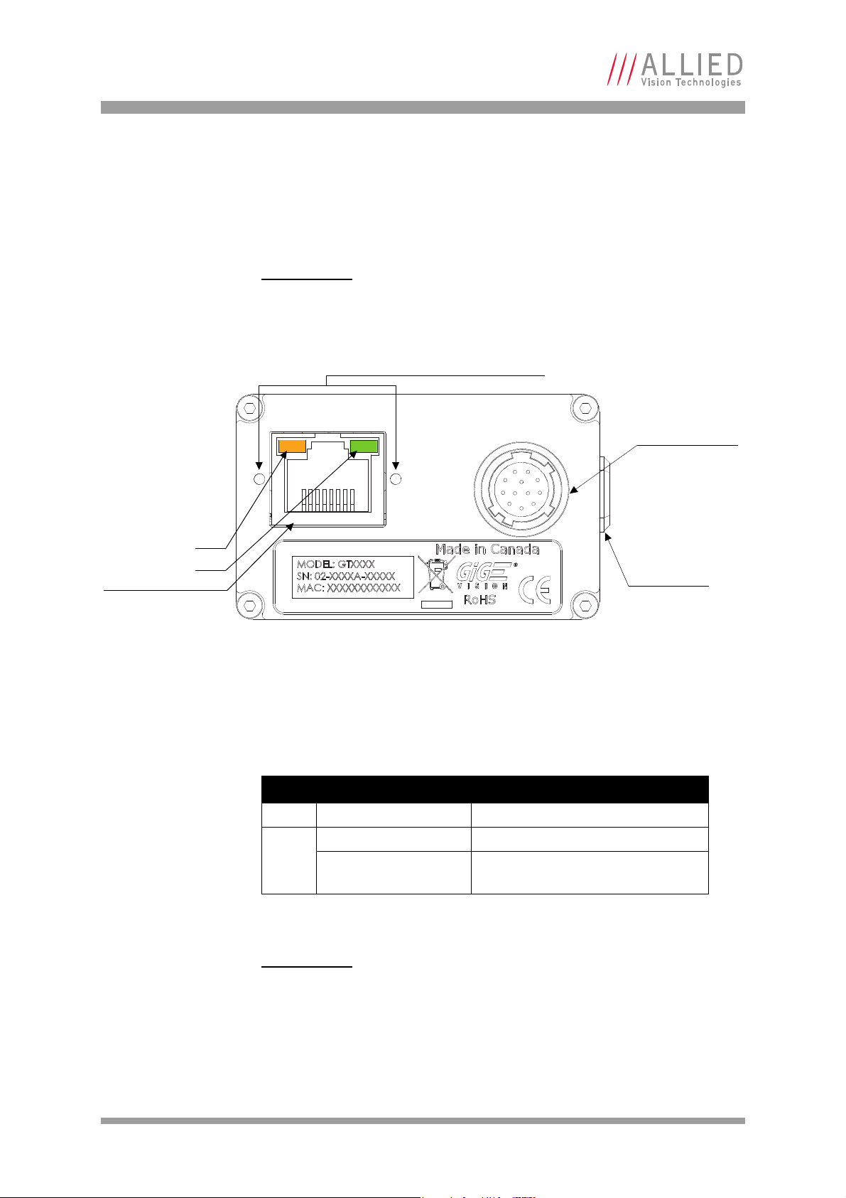
Camera interfaces
AUTO IRIS PORT
I/O PORT:
CAMERA POWER
EXTERNAL SYNC IO
RS-232 TX/RX
GIGABIT ETHERNET PORT
LED1
LED2
GIGABIT ETHERNET CABLE MOUNTING HOLES
Camera interfaces
This chapter provides information on Gigabit Ethernet port, inputs and outputs,
and trigger features.
www
For more information on GigE accessories:
http://www.alliedvisiontec.com/emea/products/
accessories/gige-accessories.html
Figure 43: Prosilica GT connection ports
Status LEDs
The color of the LEDs has the following meaning:
LED Color Status
LED1 Flashing/solid orange Ethernet activity
LED2 Flashing green Camera is powered
Solid green Camera is booted, and link with the
host is established
Table 23: Status of LEDs in Prosilica GT
Note
Once the camera is booted, LED2 will remain solid green
as long as the camera is powered, even if connection
with the host is lost.
AVT Prosilica GT Technical Manual V2.1.0
58
Page 59
Camera interfaces
Gigabit Ethernet port
The Prosilica GT is powered through the 12-pin Hirose Camera I/O port, or the
Gigabit Ethernet port by using any standard Power over Ethernet (PoE) supported network card, switch, or injector. AVT recommends using Category 6 or
higher compatible cabling for best performance.
www
www
Note
Note
The AVT GigE Installation Manual offers detailed instructions
for using Prosilica GT cameras.
http://www.alliedvisiontec.com/fileadmin/content/PDF/
Products/Technical_Manual/GigE_Install_Manual/
AVT_GigE_Installation_Manual.pdf
See Hardware Selection for AVT GigE Cameras application
note for a list of recommended Ethernet adapters:
http://www.alliedvisiontec.com/fileadmin/content/PDF/
Support/Application_Notes/
Hardware_Selection_for_AVT_GigE_Cameras.pdf
A standard Ethernet adapter is available for purchase from AVT:
AVT P/N: 02-3002A
Model: Intel Pro 1000/PT
A dual port PoE Ethernet adapter is available for purchase from
AVT:
AVT P/N: 2685
Model: Adlink GIE62+
Cable lengths up to 100 m are supported.
Note
The 8-pin RJ-45 jack has the pin assignment according to the
Ethernet standard (IEEE 802.3 1000BASE-T).
Prosilica GT cameras support cables with horizontal locking
screw connector for a secured connection (see figure 43).
AVT recommends using locking-screw cables from Components
Express, Inc. for a perfect fit. Visit the CEI product configurator
to customize the cable according to your needs.
AVT Prosilica GT Technical Manual V2.1.0
59
Page 60
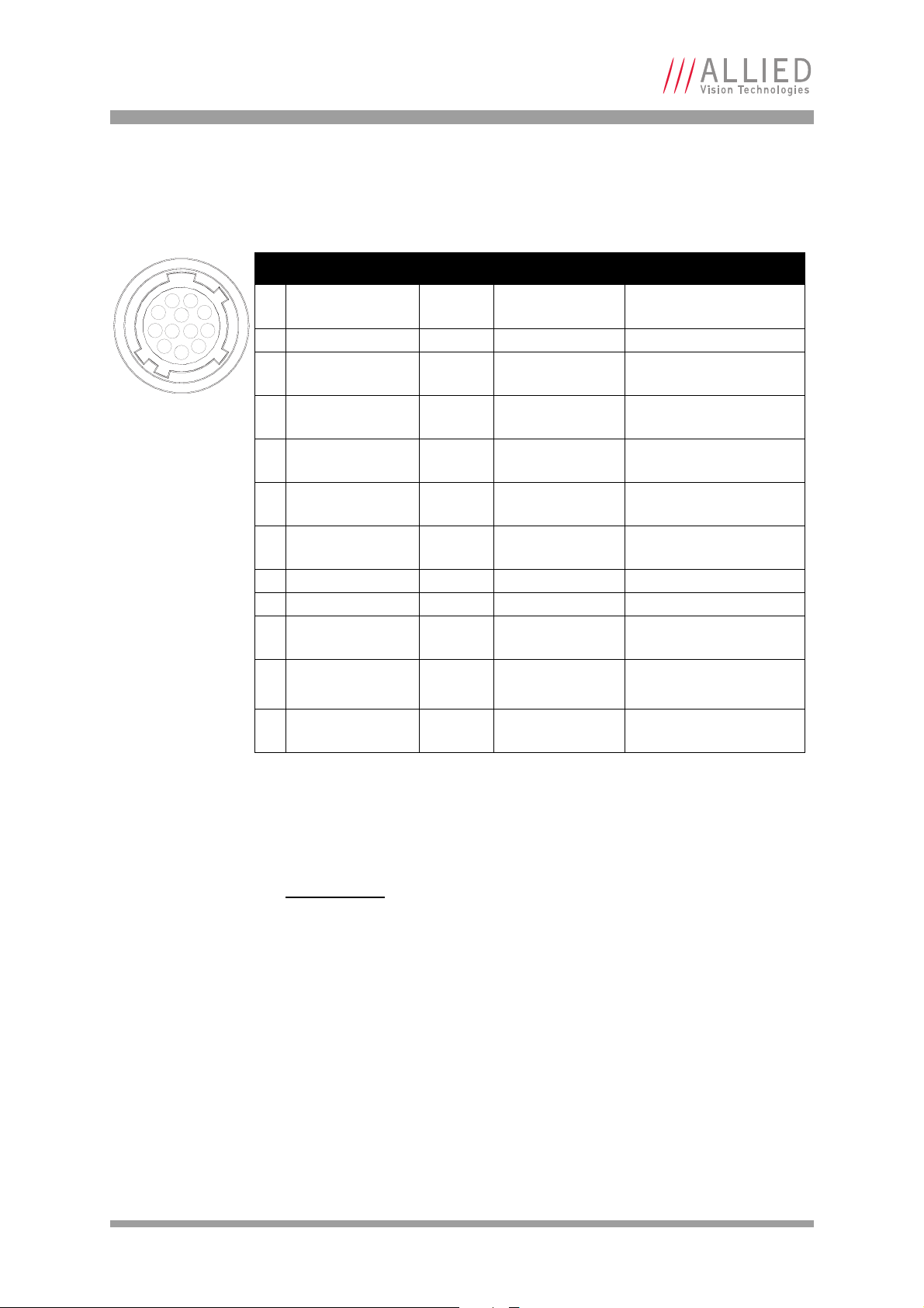
Camera interfaces
Pin Signal Direction Level Description
1 Camera GND In GND for RS232 and
ext. power
Ground for camera power
supply, and RS-232
2 Camera Power In 7–25 VDC Camera power supply
3 Out 4 Out Open emitter max.
20 mA
Output 4
opto-isolated (SyncOut4)
4In 1 In LVTTL
max. 3.3 V
Input 1
non-isolated (SyncIn1)
5 Out 3 Out Open emitter max.
20 mA
Output 3
opto-isolated (SyncOut3)
6 Out 1 Out 3.3 V LVTTL
max. 50 µA
Output 1
non-isolated (SyncOut1)
7 Isolated IO GND In/Out Common GND for
In/Out
Isolated input and output
signal ground
8 RxD RS-232 In RS-232 Terminal receive data
9 TxD RS-232 Out RS-232 Terminal transmit data
10 Isolated Out Power In Common VCC for
outputs 5–24 VDC
Power input
for opto-isolated outputs
11 In 2 In U
in
(high) = 5–24 V
U
in
(low) = 0–0.8 V
Input 2
opto-isolated (SyncIn2)
12 Out 2 Out 3.3 V LVTTL
max. 50 µA
Output 2
non-isolated (SyncOut2)
1 9
8
7
6
5
4
3
2
11 12
10
Camera I/O connector pin assignment
Figure 44: Camera I/O connector pin assignment
The General Purpose I/O port uses a Hirose HR10A-10R-12PB connector on the
camera side. The mating cable connector is Hirose HR10A-10P-12S.
Note
The cable side Hirose connector is available for purchase
from AVT.
AVT P/N: K7600040 or 02-7002A
AVT Prosilica GT Technical Manual V2.1.0
60
Page 61

Camera interfaces
I/O definition
Camera Power
The Prosilica GT camera can be powered through the Hirose I/O port, via Pin 1
Camera GND and Pin 2 Camera Power, or through the Gigabit Ethernet port if
using a power over Ethernet (PoE) supported network card, switch, or injector.
Cameras powered by both the Hirose I/O port and the Gigabit Ethernet port will
use the power provided by Hirose I/O port only.
Pin 2, Camera Power, supports an input voltage range of 7–25 VDC. The camera
will not power in reverse polarity. Exceeding the 25 V will damage the camera.
Note
A 12 V power adapter with Hirose connector is available for purchase from AVT:
• AVT P/N 02-8003A North America Supply
• AVT P/N 02-8004A Universal Supply
Isolated IO ground
The Isolated IO GND connection provides the user ground reference and return
path for In 2, Out 3, and Out 4. It is recommended that the ground wiring be
physically close to the In/Out wiring to prevent parasitic coupling. For example, a good cable design connects In 2 to one conductor of a twisted pair, Iso-
lated IO GND to the second conductor of the same twisted pair.
RxD RS-232 and TxD RS-232
These signals are RS-232 compatible. These signals are not optically isolated.
Tie RS-232 ground to Camera GND to complete the RS-232 circuit. Communica-
tion is at 11520 baud.
www
For complete RS-232 description and usage, see:
http://www.alliedvisiontec.com/fileadmin/content/PDF/
Support/Application_Notes/AppNote_-_RS232_AVT_GigE.pdf
Isolated Out Power
The Isolated Out Power connection provides power for isolated signals Out 3
and Out 4. The voltage requirement is 5–24 VDC. The current requirement for
this supply is a function of the optical isolator collector current and the number
of outputs used in the system. Isolated Out Power wiring should be physically
close to Out 3 / Out 4 wiring to prevent parasitic coupling.
AVT Prosilica GT Technical Manual V2.1.0
61
Page 62

Camera interfaces
Input triggers
Input triggers allow the camera to be synchronized to an external event. The
camera can be programmed to trigger on the rising edge, falling edge, both
edges, or level of the signal. The camera can also be programmed to capture an
image at some programmable delay time after the trigger event.
In 1 – non-isolated
In 1 is not electrically isolated and can be used when environmental noise is
inconsequential and faster trigger response is required. The required trigger
signal is low voltage TTL 3.3 V. Tie trigger ground to Camera GND to complete
the trigger circuit.
Caution
Exceeding 5.1 V on In 1 can permanently damage the camera
In 2 – opto-isolated
In 2 is optically isolated and can be used in electrically noisy environments to
prevent false trigger events. Tie trigger ground to Isolated IO GND to complete
the trigger circuit. Compared to the non-isolated trigger, In 2 has a longer
propagation time. It can be driven from 5 to 24 V with a minimum current
source of 5 mA.
Output signals
Output signals can be assigned to a variety of internal camera signals via software. They can be configured to active high or active low. The internal camera
signals are listed as follows:
Exposing Corresponds to when camera is integrating light.
Trigger Ready Indicates when the camera is ready to accept a trigger signal.
Trigger Input A relay of the trigger input signal used to “daisy chain” the
trigger signal for multiple cameras.
Readout Valid when camera is reading out data.
Imaging Valid when camera is exposing or reading out.
Strobe Programmable pulse based on one of the above events.
GPO User programmable binary output.
AVT Prosilica GT Technical Manual V2.1.0
62
Page 63
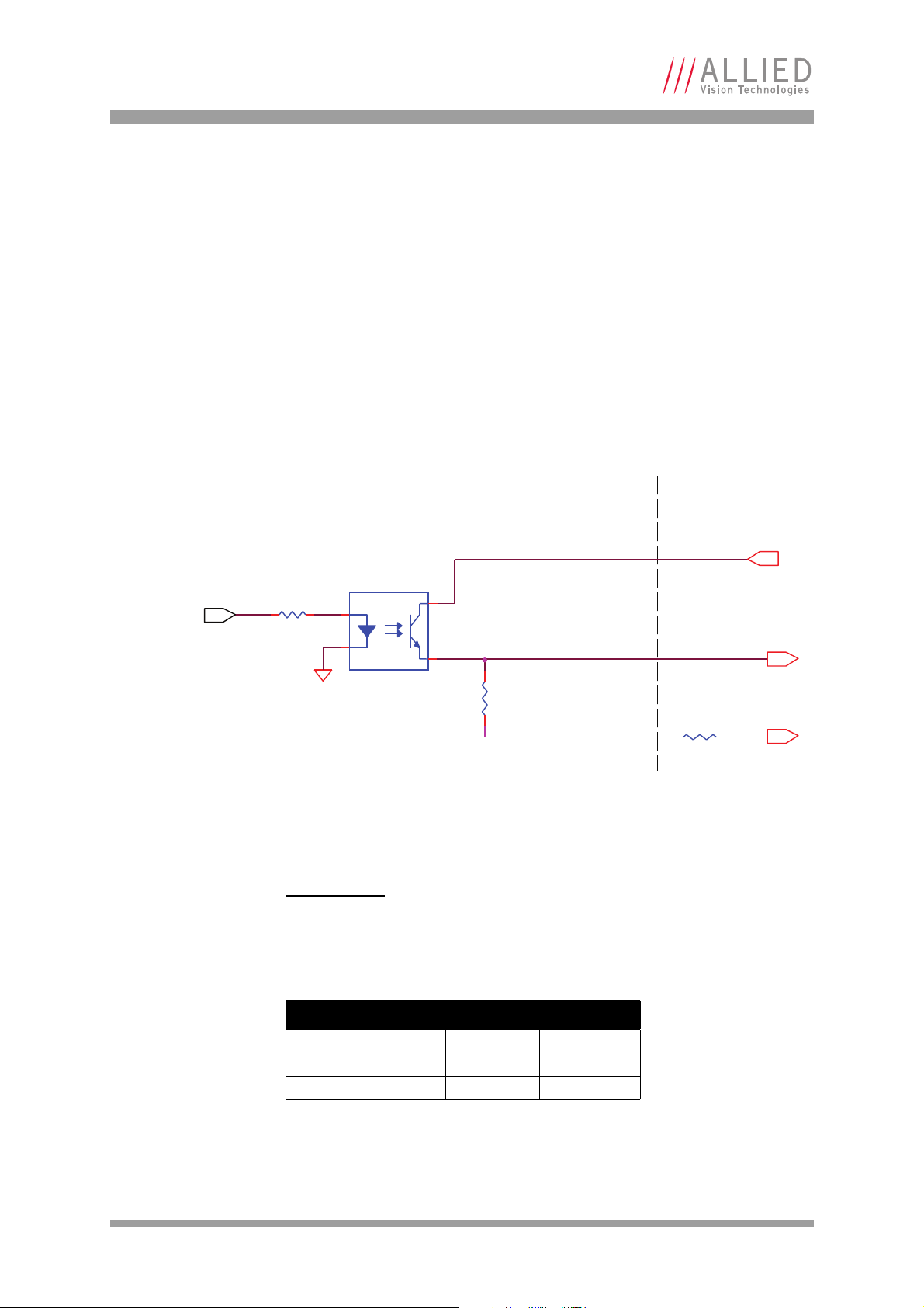
Camera interfaces
OUT 3 / OUT 4
422R
ISOLATED OUT POWER
4.75 K
ISOLATED IO GND
TCMT1107
1
2
4
3
3.3 V CAMERA
LOGIC SIGNAL
R
Out 1 and 2 – non-isolated
Out 1 and Out 2 signals are not electrically isolated and can be used when environmental electrical noise is inconsequential and faster trigger response is
required. Tie signal ground to Camera GND to complete the external circuit. The
output signal is a low voltage TTL, maximum 3.3 V. Not suitable for driving
loads in excess of 50 μA.
Out 3 and 4 – opto-isolated
Out 3 and Out 4 signals are optically isolated and require the user to provide a
voltage level, Isolated Out Power. Tie signal ground to Isolated IO GND to
complete the external circuit. Isolated Out Power can be configured between
5–24 V. An example of the functional circuit is indicated in the following diagram.
EXTERNALCAMERA INTERNAL
Figure 45: Prosilica GT Out 3 / Out 4 trigger circuit
Trigger current, and OUT ICC are a function of Isolated Out Power voltage.
Note
If Isolated Out Power = 24 V, an additional load resistance, R
is required to limit OUT ICC.
Isolated Out Power OUT ICC R LOAD
5 V 1.0 mA 0 Ω
12 V 2.5 mA 0 Ω
24 V 1.2 mA 15 KΩ
Table 24: Prosilica GT trigger circuit values
AVT Prosilica GT Technical Manual V2.1.0
63
Page 64

Camera interfaces
PIN 3
PIN 1
PIN 2
PIN 4
Lens control
Prosilica GT standard and long cameras
Prosilica GT standard and long cameras can be used with C-/CS-Mount auto iris
lenses of DC type, and P-Iris type.
Both DC and P-Iris lens types use the same standard connector, shown left,
located on the side of the camera. Lens type is automatically determined by the
camera on power-up. Connecting the lens after the camera is powered will not
damage the lens, but it will not be recognized by the camera; therefore, the relevant camera control attributes will not function. If this occurs, disconnect and
reconnect the camera power supply.
Note
Figure 46: Prosilica GT lens control port
DC AutoIris Mode P-Iris Mode
Video-type auto iris lenses are not supported.
Motorized CCTV lenses are not supported.
***Read lens descriptions carefully before purchasing***
For example, a “motorized iris lens” may be a bipolar single
axis motorized lens, and not a DC auto iris or P-Iris lens
PIN NUMBER PIN FUNCTION VOLTAGE MAX CURRENT PIN NUMBER PIN FUNCTION VOLTAGE MAX CURRENT
1 Damp – (input) N/A N/A 1 Coil 1 A (output) 0 V or 3.3 V 100 mA
2 Damp + (input) N/A N/A 2 Coil 2 A (output) 0 V or 3.3 V 100 mA
3 Drive + (output) 3.3 V 50 mA 3 Coil 2 B (output) 0 V or 3.3 V 100 mA
4 Drive – (output) 0–3.3 V 50 mA 4 Coil 1 B (output) 0 V or 3.3 V 100 mA
Table 25: Lens control port wiring
AVT Prosilica GT Technical Manual V2.1.0
64
Page 65

Camera interfaces
DC-Iris lenses
The Prosilica GT standard and long cameras operate with any standard DC-type
auto iris lens. AVT tested lenses include Fujinon DV10x8SA-SA1L, Computar
HG2Z0414FC-MP, and Pentax C61227DCPS.
DC-type auto iris lenses are continuously driven by a voltage (0–3.3 V) from the
camera lens control port. This voltage level determines whether the lens opens
or closes, and is calculated based on the applicable iris camera attributes.
Operation
1. Connect a DC-Iris lens to the camera before powering up the camera.
2. Power up camera, and open camera control software.
3. Set camera to live image with desired ExposureValue and GainValue attri-
butes.
4. Set IrisMode = DCIris. Camera uses an automatic algorithm to determine
correct lens iris position based on the IrisVideoLevel attribute.
5. If lens operation is too slow or oscillates, see LensDCDriveStrength.
www
DC-Iris controls are described further in the following documents:
PvAPI users: AVT GigE Camera and Driver Attributes document
VIMBA users: AVT GigE Camera and Driver Features document
P-Iris lenses
P-Iris (Precise iris) lenses allow the camera to adjust to an exact F-number without drift, through the usage of a stepper motor. The host system knows the
exact position of the iris at all times, allowing for a closed loop feedback system.
Operation
1. Connect a P-Iris lens to the camera before powering up the camera.
2. Power up camera, and open camera control software.
3. Set camera to live image with desired ExposureValue and GainValue attri-
butes.
4. Set LensPIrisFrequency as specified by lens documentation, or in supported P-Iris lens list, as described in the next section. All P-Iris lenses
tested thus far operate well between [100-200].
5. Set LensPIrisNumSteps as specified by lens documentation, or in supported P-Iris lens list, as described in the next section.
6. Set IrisMode attribute to PIrisAuto or PIrisManual. PIrisAuto uses an
automatic algorithm to determine correct LensPIrisPosition based on the
IrisVideoLevel attribute. PirisManual allows manual control of LensPIrisPosition.
AVT Prosilica GT Technical Manual V2.1.0
65
Page 66

Camera interfaces
EF-Mount
www
www
P-Iris controls are described further in the following documents:
PvAPI users: AVT GigE Camera and Driver Attributes document
VIMBA users: AVT GigE Camera and Driver Features document
For a list of P-Iris supported lenses, along with their LensPIrisFrequency and LensPIrisNumSteps specifications:
http://www.alliedvisiontec.com/fileadmin/content/PDF/
Support/Application_Notes/AppNote_-_Piris_Lenses_Supported_by_Prosilica_GT_Cameras.pdf
Prosilica GT large format cameras
Electro-Focus (EF) lens control is available on the Prosilica GT large format cameras using -18 modular option. EF lens control allows focus and aperture control via host software.
www
See AVT Modular Concept for information on lens mount
options available with Prosilica GT large format cameras:
http://www.alliedvisiontec.com/us/support/downloads/
product-literature/avt-modular-concept.html
Figure 47: Prosilica GT large format camera with EF-Mount
Operation
1. Connect an EF lens to the camera before powering up the camera.
2. Power up camera, and open camera control software.
AVT Prosilica GT Technical Manual V2.1.0
66
Page 67

Camera interfaces
Caution
EF lens controls will NOT function if powered via PoE.
EF lens control requires the camera to be powered by
Camera Power (pin 2) on the camera Hirose connector.
3. Use EFLensInitialize command to initialize the EF lens. This command is
automatically executed on power up and/or when lens is attached to camera.
4. Adjust the focus and aperture using EFLensFocus and EFLensFStop con-
trols, respectively.
5. If lens does not operate as expected, see EFLensState and EFLensLastError.
www
EF lens controls are described further in EFLensControl section
of following documents:
PvAPI users: AVT GigE Camera and Driver Attributes document
VIMBA users: AVT GigE Camera and Driver Features document
AVT Prosilica GT Technical Manual V2.1.0
67
Page 68

Camera trigger
TO CAMERA LOGIC
CAMERA GND
1Y
SN74LVC2G34DCKR
2
3
6
4
IN 1
DS
G
180 R
1/10 W
2Y
1A
2A
CAMERA INTERNAL EXTERNAL
TO CAMERA LOGIC
ISOLATED IO GND
PS9117A-F3-AX
1
2
4
3
5
3.3 V
IN 2
DS
G
180 R
1/10 W
3.3 V
CAMERA INTERNAL EXTERNAL
4.75 K
5.1 V, 150 mW
50 V, 1 A
Camera trigger
Input: Non-isolated and opto-isolated internal circuit
Figure 48: Prosilica GT internal circuit diagram for input trigger
AVT Prosilica GT Technical Manual V2.1.0
68
Page 69

Camera trigger
3.3 V CAMERA LOGIC
3.3 V
OUT 1
CAMERA INTERNAL EXTERNAL
3.3 V
4.75 K
DMN3404L-7
OUT 3 / OUT 4
422R
ISOLATED OUT POWER
4.75 K
ISOLATED IO GND
EXTERNALCAMERA INTERNAL
TCMT1107
1
2
4
3
3.3 V CAMERA
LOGIC SIGNAL
R
Output: Non-isolated internal circuit
Figure 49: Prosilica GT internal circuit diagram for non-isolated output trigger
Output: Opto-isolated internal circuit
Figure 50: Prosilica GT internal circuit diagram for opto-isolated output trigger
AVT Prosilica GT Technical Manual V2.1.0
69
Page 70

Camera trigger
User trigger
Logic trigger
Exposure
Readout
Trigger ready
Imaging
Tpd
Trigger
latency
Interline time
Exposure
start delay
Trigger
jitter
Idle
Registered
exposure
time
Readout time
N
N+ 1
N
N+ 1
Note: Jitter at the
beginning of an exposur
e
has no eect on the
length of exposure.
Trigger timing diagram
Figure 51: Prosilica GT internal signal timing waveforms
Notes on triggering
Term Definition
User trigger Trigger signal applied by the user (hardware
trigger, software trigger)
Logic trigger Trigger signal seen by the camera internal logic
(not visible to the user)
Tpd Propagation delay between the user trigger and
Exposure High when the camera image sensor is integrating
Readout High when the camera image sensor is reading out
Trigger latency Time delay between the user trigger and the start
Trigger jitter Error in the trigger latency time
Table 26: Explanation of signals in timing diagram
the logic trigger
light
data
of exposure
AVT Prosilica GT Technical Manual V2.1.0
70
Page 71

Camera trigger
Term Definition
Trigger ready Indicates to the user that the camera will accept
the next trigger
Registered exposure time Exposure time value currently stored in the camera
memory
Exposure start delay Registered exposure time subtracted from the
readout time and indicates when the next exposure
cycle can begin such that the exposure will end
after the current readout
Interline time Time between sensor row readout cycles
Imaging High when the camera image sensor is either
exposing and/or reading out data
Idle High if the camera image sensor is not exposing
and/or reading out data
Table 26: Explanation of signals in timing diagram
Trigger rules
Note
The user trigger pulse width should be at least three times the
width of the trigger latency as indicated in chapter
Specifications on page 13.
•The end of exposure will always trigger the next readout.
•The end of exposure must always end after the current readout.
•The start of exposure must always correspond with the interline time if
readout is true.
• Exposure start delay equals the readout time minus the registered expo-
sure time.
Triggering during the idle state
For applications requiring the shortest possible Trigger Latency and the smallest
possible Trigger Jitter the User Trigger signal should be applied when Imaging is
false and Idle is true. In this case, Trigger Latency and Trigger Jitter are as indi-
cated in the camera Specifications section.
Triggering during the readout state
For applications requiring the fastest triggering cycle time whereby the camera
image sensor is exposing and reading out simultaneously, apply the User Trigger
signal as soon as a valid Trigger Ready is detected. In this case, Trigger Latency
and Trigger Jitter can be up to 1 row time since Exposure must always begin on
an Interline boundary.
AVT Prosilica GT Technical Manual V2.1.0
71
Page 72

Firmware update
Firmware update
Firmware updates are carried out via the GigE connection. AVT provides an
application for all Prosilica GT cameras that loads firmware to the camera using
a simple interface. New feature introductions and product improvements motivate new firmware releases. All users are encouraged to use the newest firmware available and complete the firmware update if necessary.
www
www
Download the latest GigE firmware loader from the AVT
website:
http://www.alliedvisiontec.com/us/support/downloads/
firmware.html
For more information on GigE firmware update:
http://www.alliedvisiontec.com/fileadmin/content/PDF/
Support/Application_Notes/AppNote__GigE_Firmware_Update.pdf
AVT Prosilica GT Technical Manual V2.1.0
72
Page 73

Resolution and ROI frame rates
Resolution and ROI frame rates
This section charts the resulting frame rate from changing sensor height from
full image to a single line.
Unless otherwise noted, sensors do not give an increase in readout speed with
a reduction in width. However, in cases where a camera is limited by frame rate
due to bandwidth restrictions, a reduction in width will give a frame rate
increase. Cameras with a “burst mode” frame rate (see chapter Specifications on
page 13) are able to output more data than the maximum available bandwidth
(124 MB/s), and will see a frame rate increase with a reduction in width.
Note
• Data was generated using StreamBytesPerSecond = 124
MB/s (full bandwidth) and an 8-bit pixel format. Frame
rates may be lower if using network hardware incapable
of 124 MB/s.
• For maximum speed advantage on quad-tap CCD sensors,
ROIs are center image, where attribute RegionY = (full
sensor height – ROI height)/2.
• There is no frame rate increase with reduced width.
• BinningY is horizontal row summing on CCD before readout. The frame rate for an ROI at the same effective
height as binning will be slower because the CCD still
needs to read out the “fast readout rows” in ROI mode.
AVT Prosilica GT Technical Manual V2.1.0
73
Page 74
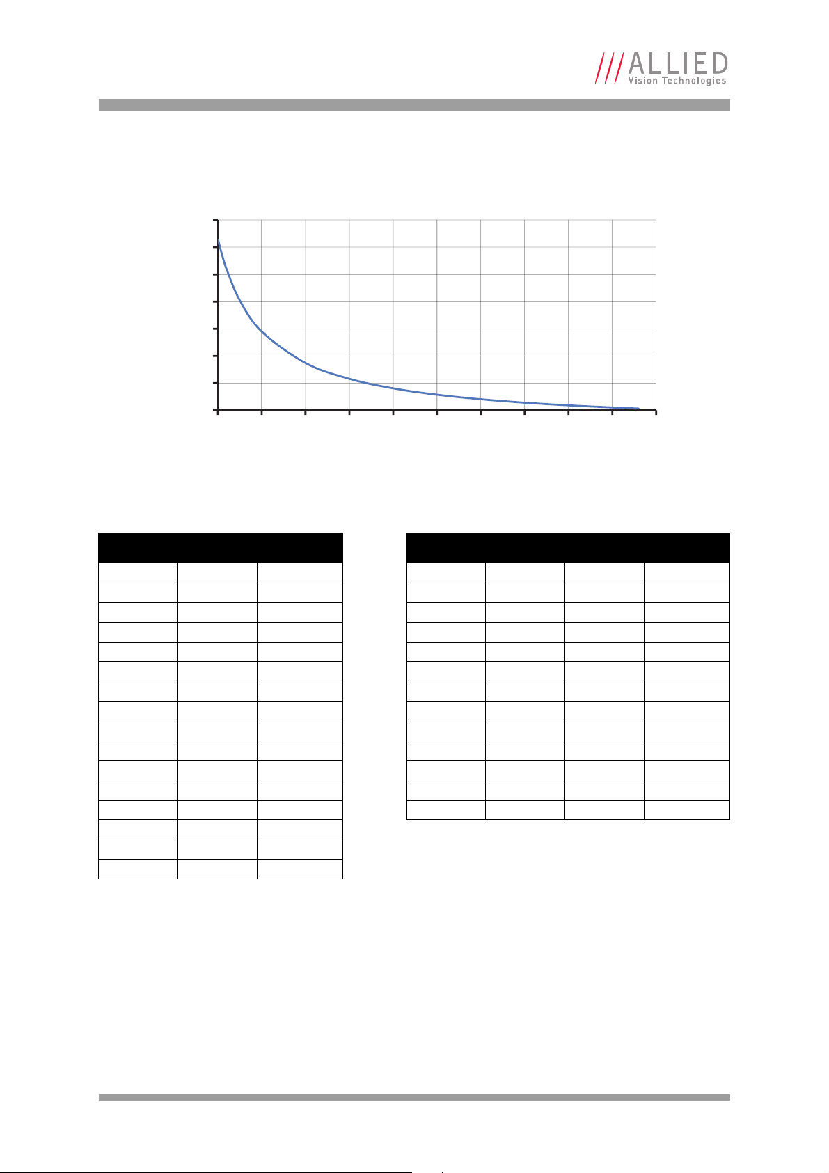
Resolution and ROI frame rates
30
80
130
180
230
280
330
380
0 100 200 300 400 500 600 700 800 900 1000
Frame Rate [fps]
Height [pixels]
Prosilica GT1290
Figure 52: Frame rate vs. height for GT1290
Height
1
Width
Frame rate
2
BinningY Height
Width
Frame rate
960 1280 33.3 2 480 1280 60.8
900 1280 35.3 3 320 1280 83.8
800 1280 39.2 4 240 1280 103.3
700 1280 44.1 5 192 1280 120
600 1280 50.4 6 160 1280 134.5
500 1280 58.8 7 137 1280 147.2
400 1280 70.5 8 120 1280 158.3
300 1280 88.0 9 106 1280 168.7
200 1280 117.1 10 96 1280 176.9
100 1280 175.0 11 87 1280 185.1
50 1280 232.4 12 80 1280 191.9
20 1280 289.5 13 73 1280 199.2
10 1280 315.2 14 68 1280 204.8
51280329.9
21280339.4
11280342.7
1
There is no frame rate increase with reduced width.
2
BinningY is horizontal row summing on CCD before readout.
AVT Prosilica GT Technical Manual V2.1.0
74
Page 75
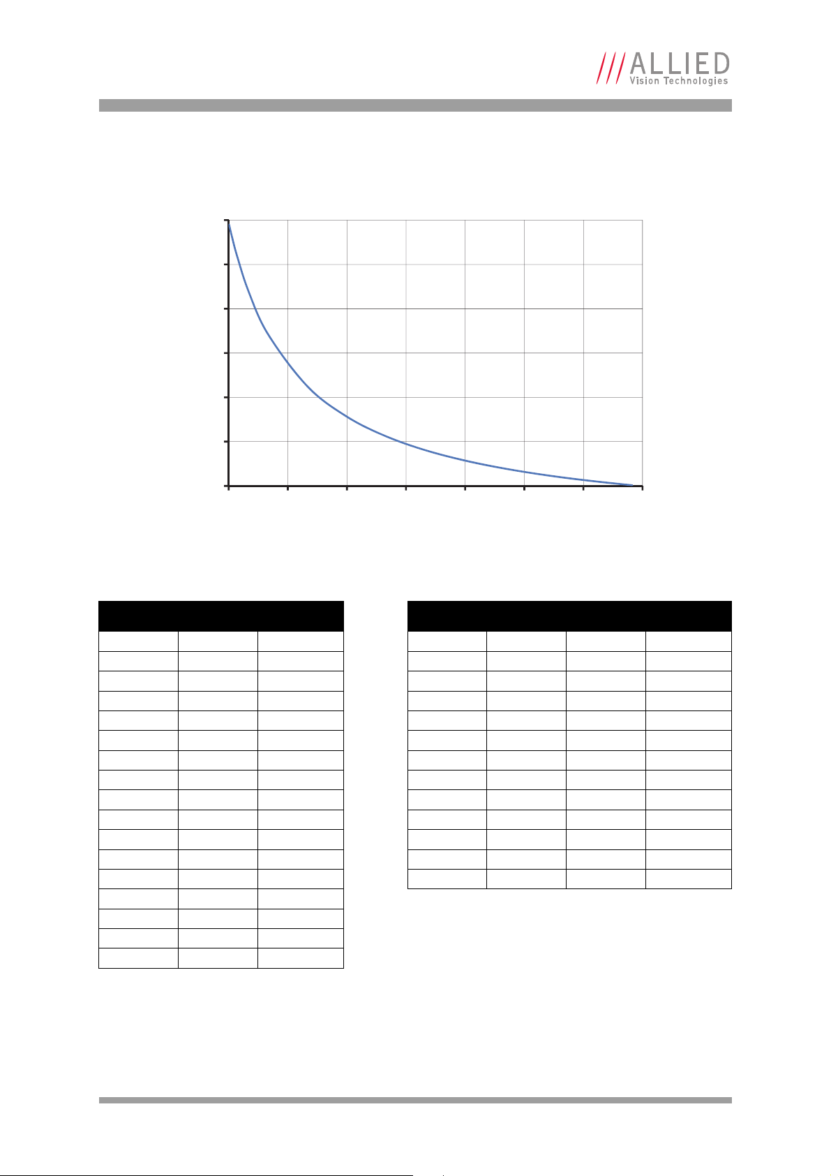
Resolution and ROI frame rates
30
60
90
120
150
180
210
0 150 300 450 600 750 900 1050
Frame Rate [fps]
Height [pixels]
Prosilica GT1380
Figure 53: Frame rate vs. height for GT1380
Height
1
Width
Frame rate
2
BinningY Height
Width
Frame rate
1024 1360 30.5 2 512 1360 53.2
1000 1360 31.1 3 341 1360 70.7
900 1360 34.0 4 256 1360 84.6
800 1360 37.5 5 204 1360 96
700 1360 41.8 6 170 1360 105.4
600 1360 47.2 7 146 1360 113.1
500 1360 54.1 8 128 1360 119.6
400 1360 63.5 9 113 1360 125.6
300 1360 76.9 10 102 1360 130.4
200 1360 97.4 11 93 1360 134.6
100 1360 132.7 12 85 1360 138.5
50 1360 162.1 13 78 1360 142.1
20 1360 186.9 14 73 1360 144.7
10 1360 197.0
51360202.5
21360205.9
11360207.0
1
There is no frame rate increase with reduced width.
2
BinningY is horizontal row summing on CCD before readout.
AVT Prosilica GT Technical Manual V2.1.0
75
Page 76

Resolution and ROI frame rates
25
75
125
175
225
275
325
0 140 280 420 560 700 840 980 1120 1260
Frame Rate [fps]
Height [pixels]
Prosilica GT1600
Figure 54: Frame rate vs. height for GT1600
Height
1
Width
Frame rate
2
BinningY Height
Width
Frame rate
1220 1620 25.8 2 610 1620 47.9
1100 1620 28.4 3 406 1620 66.9
1000 1620 31.0 4 305 1620 83.3
900 1620 34.0 5 244 1620 97.8
800 1620 37.8 6 203 1620 110.7
700 1620 42.5 7 174 1620 122.1
600 1620 48.5 8 152 1620 132.4
500 1620 56.5 9 135 1620 141.2
400 1620 67.7 10 122 1620 149.6
300 1620 84.4 11 110 1620 157.7
200 1620 112.1 12 101 1620 164.4
100 1620 166.6 13 93 1620 170.9
50 1620 220.2 14 87 1620 176
20 1620 272.9
10 1620 296.5
51620310.0
21620318.6
11620321.6
1
There is no frame rate increase with reduced width.
2
BinningY is horizontal row summing on CCD before readout.
AVT Prosilica GT Technical Manual V2.1.0
76
Page 77
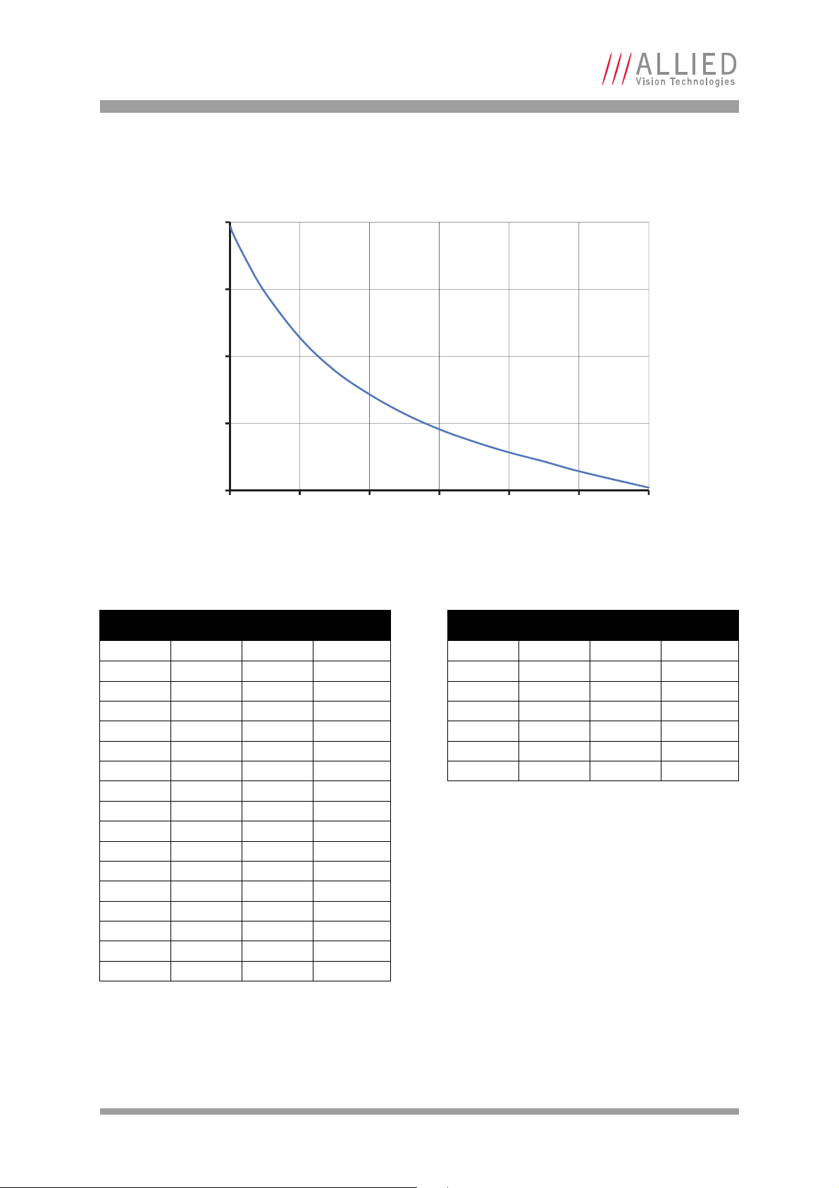
Resolution and ROI frame rates
60
110
160
210
260
0 200 400 600 800 1000 1200
Frame Rate [fps]
Height [pixels]
Prosilica GT1660
Figure 55: Frame rate vs. height for GT1660
Height
1
Width2RegionY Frame rate
3
BinningY Height
Width Frame rate
1200 1600 0 62.1 2 600 1600 121
1000 1600 100 74.3 3 400 1600 165.4
900 1600 150 81.6 4 300 1600 202.8
800 1600 200 88.4 5 240 1600 234.2
700 1600 250 96.3 6 200 1600 260.8
600 1600 300 105.6 7 170 1600 284
500 1600 350 117.2 8 150 1600 303.1
400 1600 400 131.6
300 1600 450 149.4
200 1600 500 174.0
100 1600 550 207.8
50 1600 575 230.2
20 1600 590 245.3
10 1600 595 250.8
5 1600 598 253.6
2 1600 599 256.5
1 1600 600 256.5
1
There is no frame rate increase with reduced width.
2
For maximum speed advantage ROIs are taken as center image, where attribute RegionY = (full sensor height – ROI height)/2.
3
BinningY is horizontal row summing on CCD before readout.
AVT Prosilica GT Technical Manual V2.1.0
77
Page 78
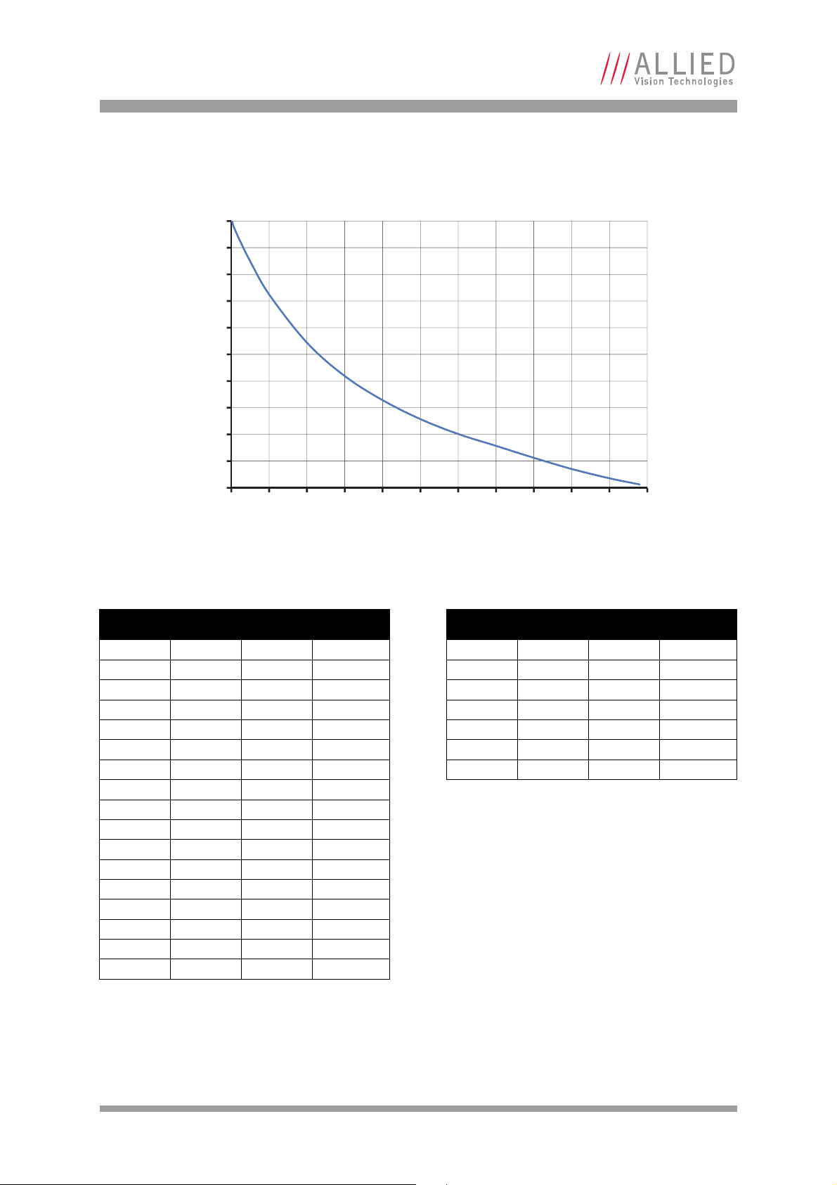
Resolution and ROI frame rates
55
75
95
115
135
155
175
195
215
235
255
0 100 200 300 400 500 600 700 800 900 1000 1100
Frame Rate [fps]
Height [pixels]
Prosilica GT1910
Figure 56: Frame rate vs. height for GT1910
Height
1
Width2RegionY Frame rate
3
BinningY Height
Width Frame rate
1080 1920 0 57.5 2 540 1920 114.1
1000 1920 40 62.1 3 360 1920 160.8
900 1920 90 69.1 4 270 1920 198.5
800 1920 140 77.5 5 216 1920 230.7
700 1920 190 86.4 6 180 1920 258.3
600 1920 240 95.3 7 154 1920 282.4
500 1920 290 106.5 8 134 1920 302.4
400 1920 340 120.7
300 1920 390 138.8
200 1920 440 163.8
100 1920 490 199.9
50 1920 515 224.7
20 1920 530 241.9
10 1920 535 248.3
5 1920 538 251.4
2 1920 539 254.8
1 1920 540 254.8
1
There is no frame rate increase with reduced width.
2
For maximum speed advantage ROIs are taken as center image, where attribute RegionY = (full sensor height – ROI height)/2.
3
BinningY is horizontal row summing on CCD before readout.
AVT Prosilica GT Technical Manual V2.1.0
78
Page 79
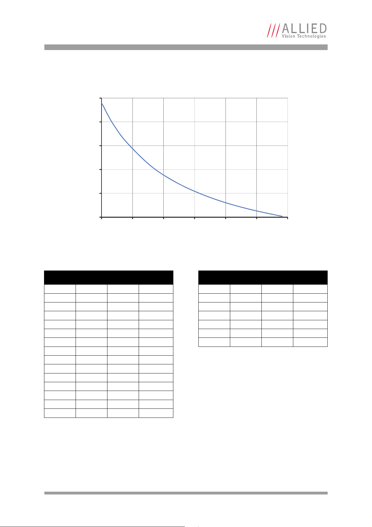
Resolution and ROI frame rates
40
60
80
100
120
140
0 250 500 750 1000 1250 1500
Frame Rate [fps]
Height [pixels]
Prosilica GT1920
Figure 57: Frame rate vs. height for GT1920
Height
1
Width2RegionY Frame rate
3
BinningY Height
Width Frame rate
1456 1936 0 40.7 2 728 1936 70.3
1400 1936 28 41.8 3 484 1936 92.8
1200 1936 128 46.4 4 364 1936 110
1000 1936 228 52.1 5 290 1936 124.1
800 1936 328 59.5 6 242 1936 135.1
600 1936 428 69.3 7 208 1936 144.1
400 1936 528 82.8 8 182 1936 151.7
200 1936 628 103.1
100 1936 678 117.2
50 1936 703 126.0
20 1936 718 132.2
10 1936 723 134.2
5 1936 726 134.7
2 1936 727 135.7
1 1936 728 135.7
1
There is no frame rate increase with reduced width.
2
For maximum speed advantage ROIs are taken as center image, where attribute RegionY = (full sensor height – ROI height)/2.
3
BinningY is horizontal row summing on CCD before readout.
AVT Prosilica GT Technical Manual V2.1.0
79
Page 80

Resolution and ROI frame rates
50
500
5000
0 100 200 300 400 500 600 700 800 900 1000 1100
Frame Rate [fps]
Height [pixels]
Prosilica GT2000
Figure 58: Frame rate vs. height for GT2000
Height
*
Width Frame rate
1088 2048 53.7
1000 2048 58.4
900 2048 64.8
800 2048 72.9
700 2048 83.2
600 2048 96.8
500 2048 115.9
400 2048 144.3
300 2048 191.2
200 2048 283.1
100 2048 545.3
50 2048 981.4
20 2048 2105.3
10 2048 2949.9
5 2048 3690.0
2 2048 4926.1
1 2048 4926.1
*There will be an increase in frame rate with reduced width if the camera is bandwidth limited.
AVT Prosilica GT Technical Manual V2.1.0
80
Page 81

Resolution and ROI frame rates
5
50
500
5000
0 300 600 900 1200 1500 1800 2100
Frame Rate [fps]
Height [pixels]
Prosilica GT2050
Figure 59: Frame rate vs. height for GT2050
Height
*
Width Frame rate
2048 2048 28.6
2000 2048 29.3
1800 2048 32.6
1600 2048 36.6
1400 2048 41.8
1200 2048 48.7
1000 2048 58.4
800 2048 72.9
600 2048 96.8
400 2048 144.3
200 2048 283.1
100 2048 545.3
50 2048 981.4
20 2048 2105.3
10 2048 2949.9
5 2048 3690.0
2 2048 4926.1
1 2048 4926.1
*There will be an increase in frame rate with reduced width if the camera is bandwidth limited.
AVT Prosilica GT Technical Manual V2.1.0
81
Page 82

Resolution and ROI frame rates
30
50
70
90
110
130
0 300 600 900 1200 1500 1800
Frame Rate [fps]
Height [pixels]
Prosilica GT2300
Figure 60: Frame rate vs. height for GT2300
Height
1
Width2RegionY Frame rate
3
BinningY Height
Width Frame rate
1752 2336 0 29.3 2 876 2336 54.2
1600 2336 76 32.1 3 584 2336 80.8
1400 2336 176 36.6 4 438 2336 99.5
1200 2336 276 42.7 5 350 2336 115
1000 2336 376 48.0 6 292 2336 128.1
800 2336 476 54.8 7 250 2336 139.5
600 2336 576 63.9 8 218 2336 148.3
400 2336 676 76.4
200 2336 776 95.2
100 2336 826 108.6
50 2336 851 116.8
20 2336 866 122.2
10 2336 871 124.5
5 2336 874 125.1
2 2336 875 125.9
1 2336 876 125.9
1
There is no frame rate increase with reduced width.
2
For maximum speed advantage ROIs are taken as center image, where attribute RegionY = (full sensor height – ROI height)/2.
3
BinningY is horizontal row summing on CCD before readout.
AVT Prosilica GT Technical Manual V2.1.0
82
Page 83

Resolution and ROI frame rates
15
25
35
45
55
65
75
85
0 300 600 900 1200 1500 1800 2100
Frame Rate [fps]
Height [pixels]
Prosilica GT2450
Figure 61: Frame rate vs. height for GT2450
Height
1
Width
Frame rate
2
BinningY Height
Width
Frame rate
2050 2448 15.0 2 1025 2448 25.4
2000 2448 15.3 3 683 2448 33.1
1800 2448 16.7 4 512 2448 38.9
1600 2448 18.4 5 410 2448 43.4
1400 2448 20.3 6 341 2448 47.1
1200 2448 22.7 7 292 2448 50.2
1000 2448 25.9 8 256 2448 52.7
800 2448 30.0 9 227 2448 54.8
600 2448 35.7 10 205 2448 56.6
400 2448 44.1 11 186 2448 58.2
200 2448 57.5 12 170 2448 59.6
100 2448 67.9 13 157 2448 60.8
50 2448 74.7 14 146 2448 61.8
20 2448 79.4
10 2448 81.1
5244882.0
2244882.5
1244882.7
1
There is no frame rate increase with reduced width.
2
BinningY is horizontal row summing on CCD before readout.
AVT Prosilica GT Technical Manual V2.1.0
83
Page 84

Resolution and ROI frame rates
15
20
25
30
35
40
45
50
55
60
65
70
75
80
0 200 400 600 800 1000 1200 1400 1600 1800 2000 2200
Frame Rate [fps]
Height [pixels]
Prosilica GT2750
Figure 62: Frame rate vs. height for GT2750
Height
1
Width2RegionY Frame rate
2200 2752 0 19.8 2 1100 2752 37
2000 2752 100 21.8 3 732 2752 50.2
1800 2752 200 23.9 4 550 2752 60.9
1600 2752 300 25.9 5 440 2752 70
1400 2752 400 28.2 6 366 2752 77.4
1200 2752 500 31.1 7 314 2752 83.8
1000 2752 600 34.5 8 274 2752 88.9
800 2752 700 38.8
600 2752 800 44.4
400 2752 900 51.7
200 2752 1000 62.0
100 2752 1050 68.9
50 2752 1075 73.0
20 2752 1090 75.6
10 2752 1095 76.5
5 2752 1098 76.9
2 2752 1099 77.4
1 2752 1100 77.4
1
There is no frame rate increase with reduced width.
2
For maximum speed advantage ROIs are taken as center image, where attribute RegionY = (full sensor height – ROI height)/2.
3
BinningY is horizontal row summing on CCD before readout.
3
BinningY Height
AVT Prosilica GT Technical Manual V2.1.0
Width Frame rate
84
Page 85

Resolution and ROI frame rates
14
19
24
29
34
39
44
49
54
59
64
69
0 500 1000 1500 2000 2500
Frame Rate [fps]
Height [pixels]
Prosilica GT3300
Figure 63: Frame rate vs. height for GT3300
Height
1
Width2RegionY Frame rate
3
BinningY Height
Width Frame rate
2472 3296 0 14.8 2 1236 3296 29.4
2200 3296 136 16.6 3 824 3296 43.1
2000 3296 236 18.2 4 618 3296 53.2
1800 3296 336 20.2 5 494 3296 62
1600 3296 436 22.8 6 412 3296 69.5
1400 3296 536 25.3 7 352 3296 75.8
1200 3296 636 27.8 8 308 3296 81.4
1000 3296 736 30.9
800 3296 836 34.7
600 3296 936 39.6
400 3296 1036 46.1
200 3296 1136 55.2
100 3296 1186 61.2
50 3296 1211 64.7
20 3296 1226 67.0
10 3296 1231 67.9
5 3296 1234 68.2
2 3296 1235 68.5
1 3296 1236 68.5
1
There is no frame rate increase with reduced width.
2
For maximum speed advantage ROIs are taken as center image, where attribute RegionY = (full sensor height – ROI height)/2.
3
BinningY is horizontal row summing on CCD before readout.
AVT Prosilica GT Technical Manual V2.1.0
85
Page 86

Resolution and ROI frame rates
13
18
23
28
33
38
43
48
53
0 250 500 750 1000 1250 1500 1750 2000 2250 2500 2750
Frame Rate [fps]
Height [pixels]
Prosilica GT3400
Figure 64: Frame rate vs. height for GT3400
Height
1
Width2RegionY Frame rate
3
BinningY Height
Width Frame rate
2704 3384 0 13.2 2 1352 3384 25.1
2600 3384 52 13.7 3 900 3384 34.1
2400 3384 152 14.8 4 676 3384 41.4
2200 3384 252 16.2 5 540 3384 47.6
2000 3384 352 17.4 6 450 3384 52.8
1800 3384 452 18.6 7 386 3384 57.2
1600 3384 552 20.1 8 338 3384 61.0
1400 3384 652 21.7
1200 3384 752 23.8
1000 3384 852 26.1
800 3384 952 29.1
600 3384 1052 32.8
400 3384 1152 37.5
200 3384 1252 43.9
100 3384 1302 48.0
50 3384 1327 50.4
20 3384 1342 51.8
10 3384 1347 52.3
5 3384 1350 52.6
2 3384 1351 52.8
1 3384 1352 52.8
1
There is no frame rate increase with reduced width.
2
For maximum speed advantage ROIs are taken as center image, where attribute RegionY = (full sensor height – ROI height)/2.
3
BinningY is horizontal row summing on CCD before readout.
AVT Prosilica GT Technical Manual V2.1.0
86
Page 87

Resolution and ROI frame rates
7
12
17
22
27
32
0 300 600 900 1200 1500 1800 2100 2400 2700 3000 3300
Frame Rate [fps]
Height [pixels]
Prosilica GT4905
Figure 65: Frame rate vs. height for GT4905
Height
1
Width2RegionY Frame rate
3
BinningY Height
Width Frame rate
3264 4896 0 7.5 2 1632 4896 15.1
3200 4896 32 7.7 3 1088 4896 20.7
3000 4896 132 8.2 4 816 4896 25.1
2800 4896 232 8.8 5 652 4896 28.8
2600 4896 332 9.5 6 544 4896 31.8
2400 4896 432 10.2 7 466 4896 34.4
2200 4896 532 11.2 8 408 4896 36.6
2000 4896 632 12.0
1800 4896 732 12.7
1600 4896 832 13.7
1400 4896 932 14.7
1200 4896 1032 15.9
1000 4896 1132 17.4
800 4896 1232 19.1
600 4896 1332 21.2
400 4896 1432 23.9
200 4896 1532 27.3
100 4896 1582 29.4
50 4896 1607 30.6
20 4896 1622 31.3
10 4896 1627 31.6
5 4896 1630 31.7
2 4896 1631 31.8
1 4896 1632 31.8
1
There is no frame rate increase with reduced width.
2
For maximum speed advantage ROIs are taken as center image, where attribute RegionY = (full sensor height – ROI height)/2.
3
BinningY is horizontal row summing on CCD before readout.
AVT Prosilica GT Technical Manual V2.1.0
87
Page 88

Resolution and ROI frame rates
7
10
13
16
19
22
0 650 1300 1950 2600 3250
Frame Rate [fps]
Height [pixels]
Prosilica GT4907
Figure 66: Frame rate vs. height for GT4907
Height
1
Width2RegionY Frame rate
3
BinningY Height
Width Frame rate
3232 4864 0 7.7 2 1616 4864 12.5
3200 4864 16 7.7 3 1076 4864 15.7
3000 4864 116 8.1 4 808 4864 17.9
2800 4864 216 8.4 5 646 4864 19.6
2600 4864 316 8.8 6 538 4864 21.0
2400 4864 416 9.2 7 460 4864 21.9
2200 4864 516 9.7 8 404 4864 22.7
2000 4864 616 10.2
1800 4864 716 10.7
1600 4864 816 11.3
1400 4864 916 12.0
1200 4864 1016 12.8
1000 4864 1116 13.7
800 4864 1216 14.8
600 4864 1316 16.0
400 4864 1416 17.4
200 4864 1516 19.1
100 4864 1566 20.0
50 4864 1591 20.6
20 4864 1606 20.9
10 4864 1611 21.0
5 4864 1614 21.1
2 4864 1615 21.1
1 4864 1616 21.1
1
There is no frame rate increase with reduced width.
2
For maximum speed advantage ROIs are taken as center image, where attribute RegionY = (full sensor height – ROI height)/2.
3
BinningY is horizontal row summing on CCD before readout.
AVT Prosilica GT Technical Manual V2.1.0
88
Page 89

Resolution and ROI frame rates
4
6
8
10
12
14
16
18
0 400 800 1200 1600 2000 2400 2800 3200 3600 4000 4400
Frame Rate [fps]
Height [pixels]
Prosilica GT6600
Figure 67: Frame rate vs. height for GT6600
Height
1
Width2RegionY Frame rate
3
BinningY Height
Width Frame rate
4384 6576 0 4.0 2 2192 6576 7.5
4000 6576 192 4.3 3 1460 6576 10.4
3500 6576 442 4.7 4 1096 6576 13.0
3000 6576 692 5.3 5 876 6576 15.3
2500 6576 942 6.0 6 730 6576 17.3
2000 6576 1192 6.9 7 626 6576 19.1
1500 6576 1442 8.1 8 548 6576 20.7
1000 6576 1692 9.8
800 6576 1792 10.8
600 6576 1892 11.9
400 6576 1992 13.3
200 6576 2092 15.0
100 6576 2142 16.0
50 6576 2167 16.6
20 6576 2182 17.0
10 6576 2187 17.1
5 6576 2190 17.2
2 6576 2191 17.2
1 6576 2192 17.2
1
There is no frame rate increase with reduced width.
2
For maximum speed advantage ROIs are taken as center image, where attribute RegionY = (full sensor height – ROI height)/2.
3
BinningY is horizontal row summing on CCD before readout.
AVT Prosilica GT Technical Manual V2.1.0
89
Page 90
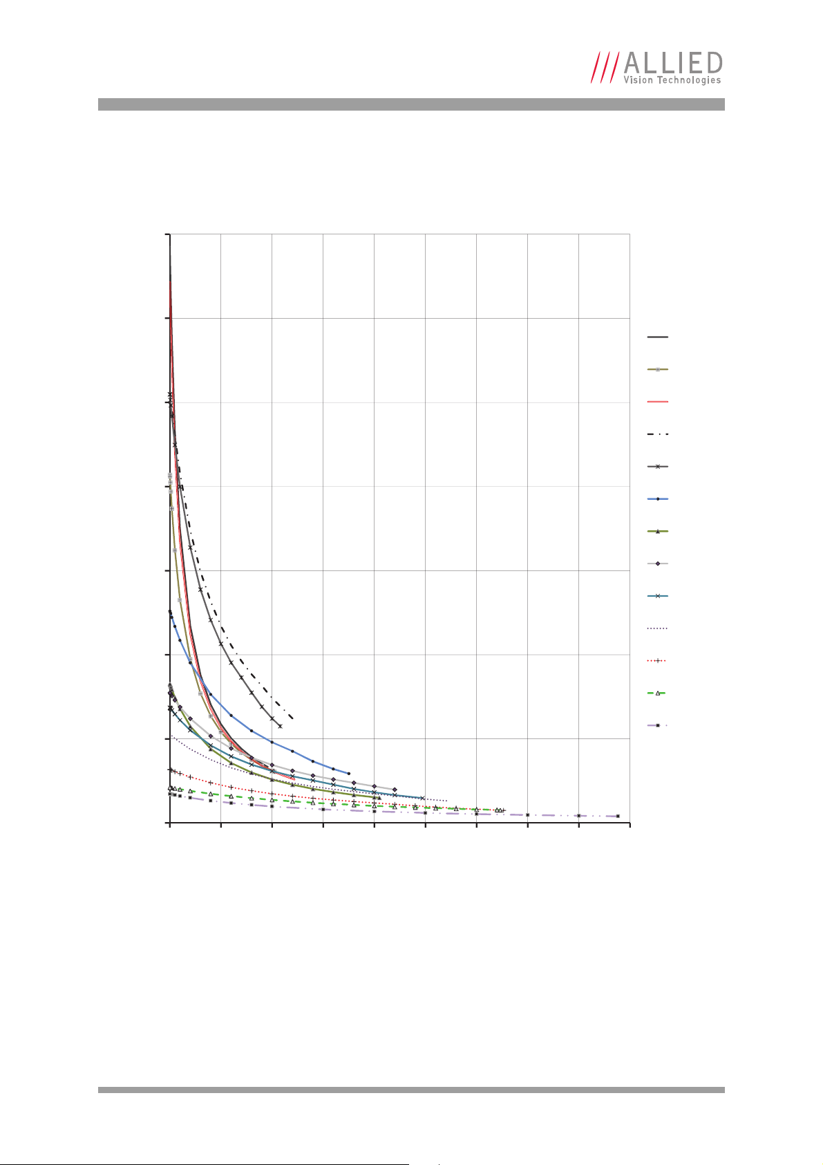
Resolution and ROI frame rates
0
50
100
150
200
250
300
350
0 500 1000 1500 2000 2500 3000 3500 4000 4500
Frame Rate [fps]
Height [pixels]
GT1290
GT1380
GT1600
GT1660
GT1910
GT2300
GT2450
GT2750
GT3300
GT3400
GT4905
GT4907
GT6600
Prosilica GT model comparison
Figure 68: Frame rate vs. height model comparison. GT2000, GT2050 not included for scale reasons
AVT Prosilica GT Technical Manual V2.1.0
90
Page 91
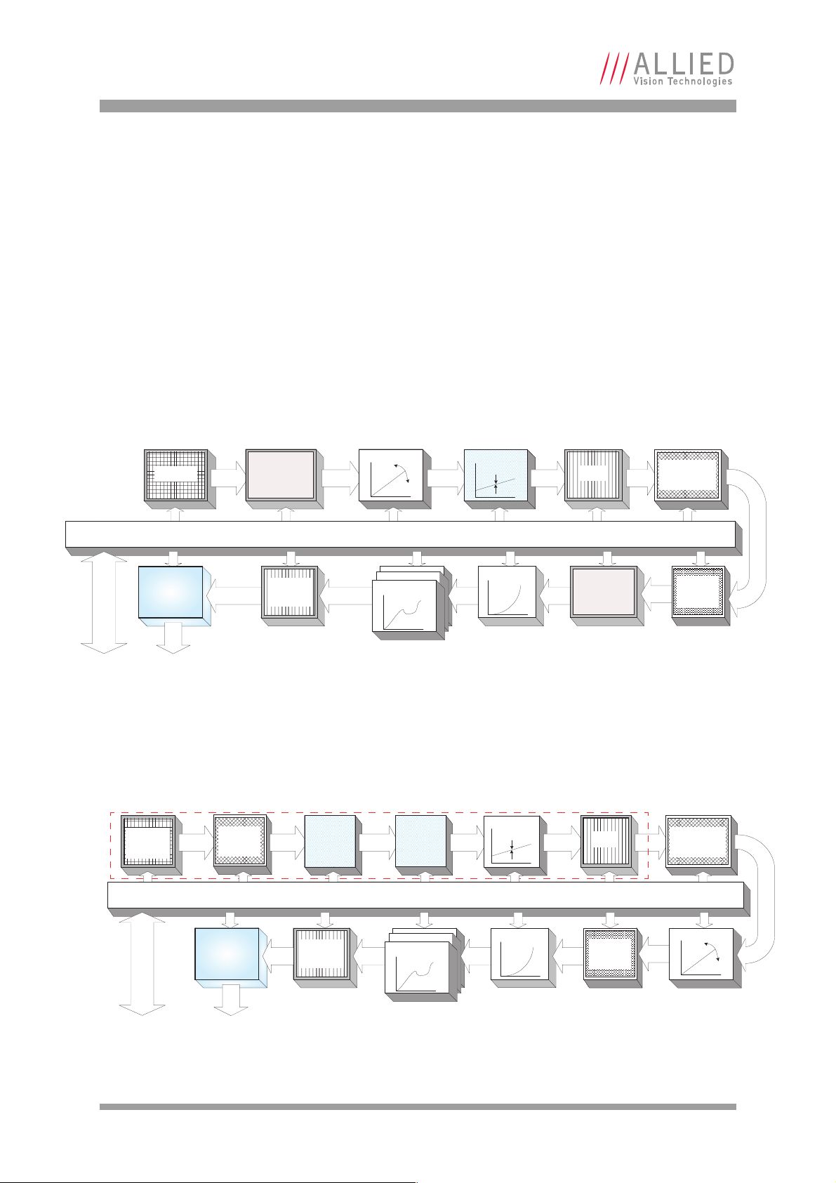
Description of the data path
12/14* bit
Sensor
Analog Analog
ADC
HIROSE I/O
RS232
Analog Analog
Vertical
binning /
Vertical ROI
14 bit
Gigabit
Ethernet
interface
‡
Factory calibrated. NOT a user control.
Oset
‡
Gain
*
12 bits with LUT , 14 bits if the LUT is bypassed
LUT
12
12
LUT
12
12
LUT 1-3
14 ĺ 12
14 bit
Gamma
14 bit
Horizontal
binning
12/14* bit
Frame
memory
14 bit
14 bit
Horizontal
ROI
Camera control
Defect
mask
GigE
HIROSE I/O
RS232
12 bit
12 bit
Gigabit
Ethernet
interface
12 bit
LUT
12
12
LUT
12
12
LUT 1-3
12 ĺ 12
12 bit
Gamma
12 bit
Frame
memory
‡
Factory calibrated. NOT a user control.
Sensor
array
Analog Analog 12 bitAnalog
Analog
Oset
Sensor
System
Gain
‡
Sensor
System
Oset
‡
Analog
Vertical
ROI
Horizontal
ROI
ADC
12 bit
Defect
mask
Camera control
Gain
GigE
Description of the data path
The following diagrams illustrate the data flow and the bit resolution of image
data. The individual blocks are described in more detail in the AVT GigE Camera
and Driver Features document.
Prosilica GT monochrome cameras
Prosilica GT with CCD sensors
GT1290, GT1380, GT1600, GT1660, GT1910, GT1920, GT2300, GT2450, GT2750,
GT3300, GT4100, GT4905, GT4907, GT6600
re 69: Block diagram of Prosilica GT monochrome cameras with CCD sensors
Figu
Prosilica GT with CMOS sensor
GT2000, GT2000 NIR, GT2050, GT2050 NIR
Internal sensor components
AVT Prosilica GT Technical Manual V2.1.0
91
Figure 70: Block diagram of Prosilica GT2000 and GT2050 monochrome cameras
Page 92

Description of the data path
14 bit
14 bit
HIROSE I/O
RS232
For on-camera interpolated PixelFormats only—outputs 8 bit.
Raw un-interpolated PixelFormats skip this block—outputs 12/14 bit.
8 bit
8 bit
Sensor
Analog Analog 14 bit
ADC
GigE
Analog
Analog
Vertical
binning /
Vertical ROI
14 bit
Gigabit
Ethernet
interface
‡
Factory calibrated. NOT a user control.
White balance
Gain
Horizontal
binning
Hue
†
Saturation
Color tranformation
*
LUT
12
12
LUT
12
12
LUT 1-3
14 ĺ 12
14 bit
Gamma
Bayer
†
Interpolation
3 X 3
12/14* bit8/12/14 bit
Frame
memory
†
12 bits with LUT, 14 bits if the LUT is bypassed.
Horizontal
ROI
14 bit
Defect
mask
Camera control
Oset
‡
HIROSE I/O
RS232
Sensor
array
Analog
Analog
12 bit
GigE
Analog
12 bit
Gamma
12 bit
LUT
12
12
LUT
12
12
12 bit
Gigabit
Ethernet
interface
Internal sensor components
12 bit
12 bit
Analog
Oset
LUT 1-3
12 ĺ 12
8 bit 8 bit8/12 bit
Frame
memory
Hue
†
Saturation
Color tranformation
Bayer
†
Interpolation
3 X 3
For on-camera interpolated PixelFormats only—outputs 8 bit.
Raw un-interpolated PixelFormats skip this block—outputs 12 bit.
‡
Factory calibrated. NOT a user control.
†
Sensor
System
Gain
‡
Sensor
System
Oset
‡
Analog
Vertical
ROI
Defect
mask
12 bit
Camera control
White balance
Horizontal
ROI
12 bit
ADC
Gain
Prosilica GT color cameras
Prosilica GT with CCD sensors
GT1290C, GT1380C, GT1600C, GT1660C, GT1910C, GT1920C, GT2300C, GT2450C,
GT2750C, GT3300C, GT4100C, GT4905C, GT4907C, GT6600C
Figure 71: Block diagram of Prosilica GT color cameras with CCD sensors
Prosilica GT with CMOS sensors
GT2000C, GT2050C
Figure 72: Block diagram of Prosilica GT2000 and GT2050 color cameras
AVT Prosilica GT Technical Manual V2.1.0
92
Page 93
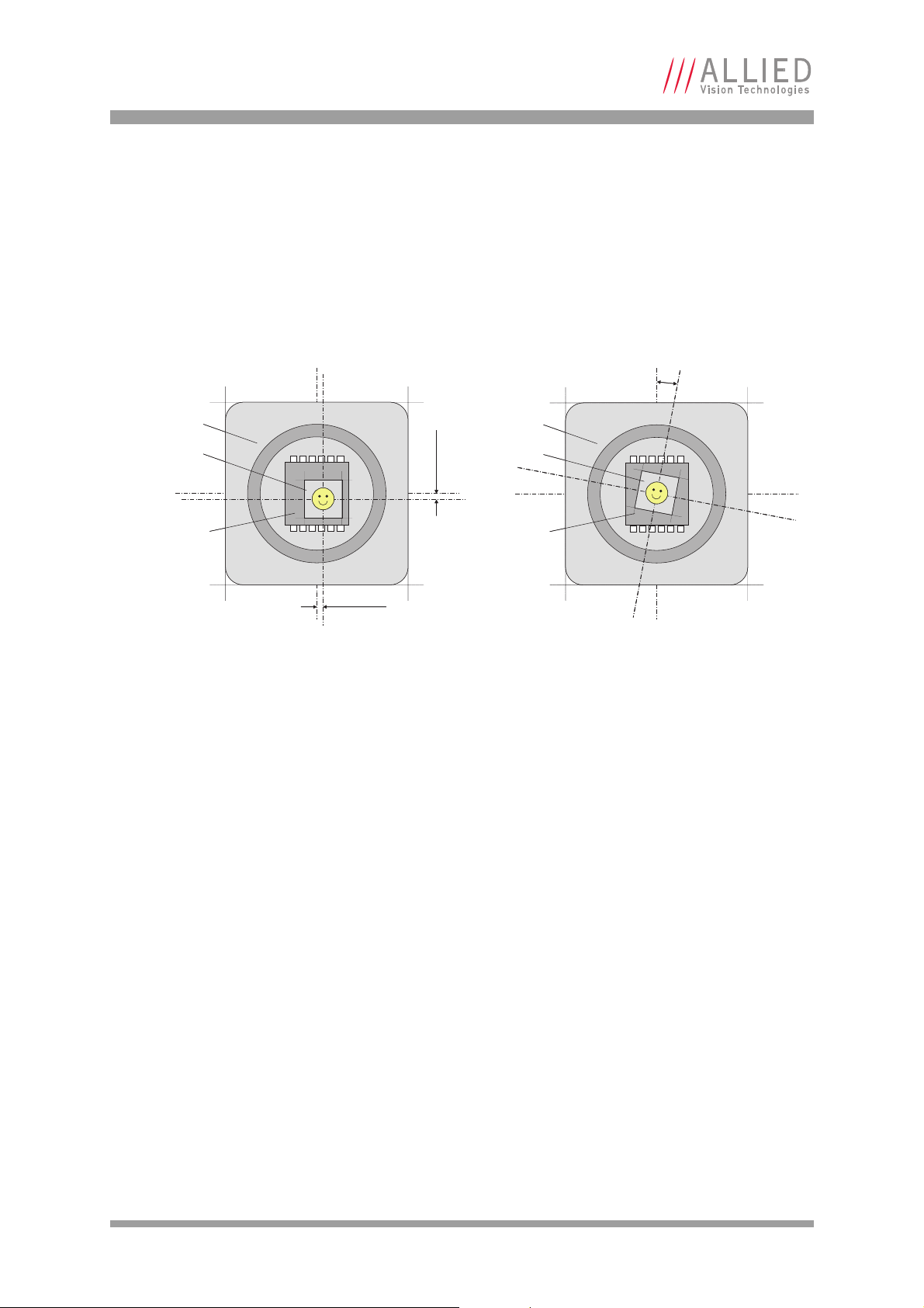
Appendix
x
y
Sensor case
D
Camera body
Pixel area
Sensor case
Camera body
Pixel area
Appendix
Sensor position accuracy of Prosilica GT standard and long cameras
Method of Positioning:
Reference points:
Accuracy:
Optical alignment of photo sensitive sensor area into camera front
module. (lens mount front flange)
Sensor: Center of pixel area (photo sensitive cells)
Camera: Center of camera front flange (outer case edges)
x/y ±250 µm (Sensor shift)
α
< 1° (Sensor rotation)
AVT Prosilica GT Technical Manual V2.1.0
93
Page 94

Additional references
Additional references
Prosilica GT webpage
http://www.alliedvisiontec.com/us/products/cameras/gigabit-ethernet/prosilica-GT.html
Prosilica GT Documentation
http://www.alliedvisiontec.com/us/support/downloads/product-literature/
prosilica-GT.html
AVT VIMBA SDK
http://www.alliedvisiontec.com/us/products/software/vimba-sdk.html
AVT GigE PvAPI SDK
http://www.alliedvisiontec.com/us/products/legacy.html
AVT Knowledge Base
http://www.alliedvisiontec.com/us/support/knowledge-base.html
AVT Case Studies
http://www.alliedvisiontec.com/emea/products/application-markets/
industrial-inspection.html
Prosilica GT Firmware
http://www.alliedvisiontec.com/us/support/downloads/firmware.html
AVT Prosilica GT Technical Manual V2.1.0
94
Page 95

Index
Index
A
Adjustment
C/CS-Mount ....................................... 56
F-Mount ............................................ 57
B
Block diagram
Prosilica GT color cameras..................... 92
Prosilica GT monochrome cameras .......... 91
Prosilica GT2000 and GT2050 cameras ..... 91
Prosilica GT2000C and GT2050C cameras .. 92
C
Camera dimensions ................................... 48
Camera GND..............................60
Camera interfaces ..................................... 58
Camera Power ..................................... 60
CE.......................................................... 12
Cleaning optics ........................................ 10
, 61, 62, 63
, 61
D
Data path................................................ 91
DC-Iris lens ........................................ 64
Declaration of conformity........................... 12
Document history ....................................... 6
, 65
E
I
Idle (signal) ............................................ 71
Imaging (signal) ...................................... 71
In 1 .................................................. 60
In 2 ............................................. 60
Integrating light (trigger)..................... 62
interline boundary.................................... 71
Interline time (signal)............................... 71
IR filter ............................................. 10
Isolated IO GND.........................60
Isolated Out Power .........................60
, 61, 62, 63
, 62
, 61, 62
, 70
, 47
, 61, 63
L
Legal notice .............................................. 2
Lens control ............................................ 64
Prosilica GT large format cameras ........... 66
Prosilica GT standard and long cameras ... 64
lens protrusion ........................................ 52
Logic trigger (definition) ........................... 70
M
Mechanical dimensions
Prosilica GT large format....................... 51
Prosilica GT long (C-Mount)................... 49
Prosilica GT long (F-Mount)................... 50
Prosilica GT standard ........................... 48
Tripod mounting plate for standard and long
GTs........................................ 55
Environmental specifications ........................9
Exposing (trigger) .................................... 71
Exposure (definition) ................................ 70
Exposure cycle (trigger)............................. 71
Exposure start delay (signal) ...................... 71
F
FCC Class A .............................................. 12
Flange focal distance................................. 52
C-Mount cross section .......................... 52
F-Mount cross section .......................... 53
G
GND for ext. power.................................... 60
O
Optical flange focal distance....................... 52
Out 1................................................. 60
Out 2................................................. 60
Out 3............................................60
Out 4............................................60
, 63
, 63
, 61, 63
, 61, 63
P
P-Iris lens .......................................... 64, 65
Precautions ............................................... 9
Propagation delay (trigger) ........................ 70
AVT Prosilica GT Technical Manual V2.1.0
95
Page 96

Index
R
Readout (definition) ................................. 70
Readout data (trigger)............................... 70
Registered exposure time (signal)................ 71
Resolution and ROI frame rates
GT model comparison........................... 90
Prosilica GT1290 ................................. 74
Prosilica GT1380 ................................. 75
Prosilica GT1600 ................................. 76
Prosilica GT1660 ................................. 77
Prosilica GT1910 ................................. 78
Prosilica GT1920 ................................. 79
Prosilica GT2000 ................................. 80
Prosilica GT2050 ................................. 81
Prosilica GT2300 ................................. 82
Prosilica GT2450 ................................. 83
Prosilica GT2750 ................................. 84
Prosilica GT3300 ................................. 85
Prosilica GT3400 ................................. 86
Prosilica GT4905 ................................. 87
Prosilica GT4907 ................................. 88
Prosilica GT6600 ................................. 89
RoHS (2011/65/EU).................................. 12
RS-232 .............................................. 60
, 61
S
Sensor position ........................................ 93
Sensor row readout cycles .......................... 71
Specifications .......................................... 13
Spectral sensitivity
Prosilica GT1290-Color ......................... 14
Prosilica GT1290-Monochrome............... 14
Prosilica GT1380-Color ......................... 16
Prosilica GT1380-Monochrome............... 16
Prosilica GT1600-Color ......................... 18
Prosilica GT1600-Monochrome............... 18
Prosilica GT1660-Color ......................... 20
Prosilica GT1660-Monochrome............... 20
Prosilica GT1910-Color ......................... 22
Prosilica GT1910-Monochrome............... 22
Prosilica GT1920-Color ......................... 24
Prosilica GT1920-Monochrome............... 24
Prosilica GT2000 / 2000 NIR-Monochrome 26
Prosilica GT2000-Color ......................... 26
Prosilica GT2050 / 2050 NIR Monochrome 28
Prosilica GT2050-Color ......................... 28
Prosilica GT2300-Color ......................... 30
Prosilica GT2300-Monochrome............... 30
Prosilica GT2450-Color......................... 32
Prosilica GT2450-Monochrome............... 32
Prosilica GT2750-Color......................... 34
Prosilica GT2750-Monochrome............... 34
Prosilica GT3300-Color......................... 36
Prosilica GT3300-Monochrome............... 36
Prosilica GT3400-Color......................... 38
Prosilica GT3400-Monochrome............... 38
Prosilica GT4905-Color......................... 41
Prosilica GT4905-Monochrome............... 41
Prosilica GT4907C ............................... 43
Prosilica GT4907-Monochrome............... 43
Prosilica GT6600-Color......................... 45
Prosilica GT6600-Monochrome............... 45
Spectral transmission
IRC30 filter ........................................ 47
Status LEDs ............................................. 58
Styles....................................................... 8
Symbols ................................................... 8
T
Time delay (trigger) .................................. 70
Tpd (definition) ....................................... 70
Trademarks ............................................... 2
Trigger jitter (definition) ........................... 70
Trigger latency (definition) ........................ 70
trigger latency time .................................. 70
Trigger ready (signal)................................ 71
Trigger rules............................................ 71
Trigger timing diagram .............................. 70
U
User trigger (definition) ............................ 70
W
Warranty................................................2, 9
AVT Prosilica GT Technical Manual V2.1.0
96
 Loading...