

Page 1
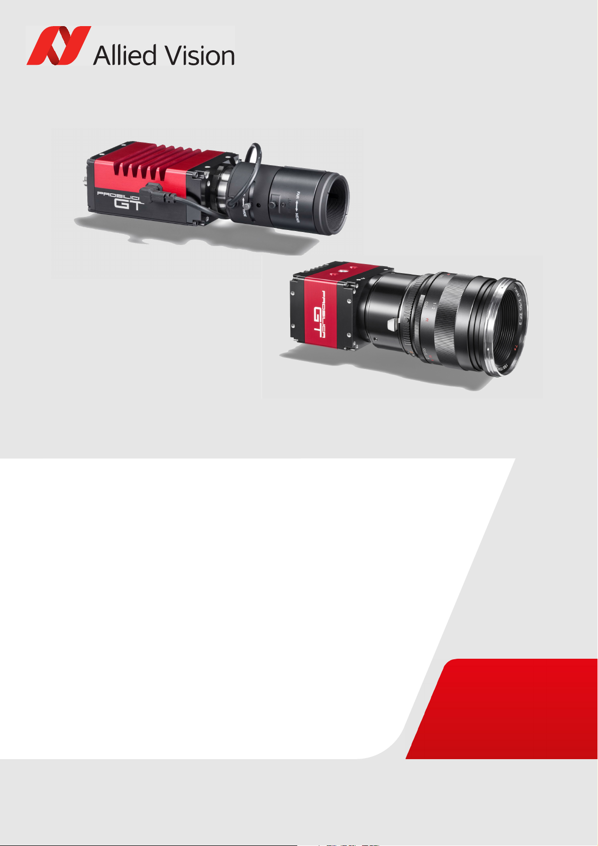
GIGE VISION CAMERAS
Prosilica GT
Technical Manual
V2.9.0
Allied Vision Technologies GmbH // Taschenweg 2a, 07646 Stadtroda / Germany 2017-Aug-04
Page 2

Prosilica GT at a glance
Prosilica GT cameras have a Gigabit Ethernet (GigE) interface and work with Gigabit
Ethernet hardware and cable lengths up to 100 m. Prosilica GT cameras are GigE
Vision V1.2 and GenICam Standard Feature Naming Convention (SFNC) V1.2.1
compliant.
Applied standards
Prosilica GT at a glance
GigE Vision®
GenICam™
The GigE Vision standard is an interface standard for digital machine vision
cameras administered by the Automated Imaging Association (AIA) that is widely
supported in the machine vision industry. In contrast, Gigabit Ethernet is the
network GigE Vision is built upon.
GenICam is a machine vision standard hosted by the European Machine Vision
Association (EMVA). The aim of GenICam is to provide a generic configuration
interface for cameras and devices independent of the used interface technology
(i.e., GigE Vision, USB3 Vision, DCAM IEEE 1394, Camera Link). This approach
enables proper interoperability between GenICam compliant hardware and
software solutions without the need for customization.
The GenICam standard consists of multiple modules that specify tasks to be solved.
Allied Vision cameras and software make use of these modules, like the Standard
Feature Naming Convention (SFNC) that standardizes feature names and types via
an XML file or the transport layer interface (GenTL) that is used to grab images.
What else do you need?
Content URL
Camera data sheets
GigE Installation Manual
GigE Features Reference
Modular Concept
3D CAD STEP files
Software and firmware downloads
https://www.alliedvision.com/en/support/
technical-documentation/prosilica-gtdocumentation.html
Technical papers and knowledge base https://www.alliedvision.com/en/support/
technical-papers-knowledge-base.html
Read this manual carefully
Learn how to protect your camera from damage and fully understand its functions.
2Prosilica GT Technical Manual V2.9.0
Page 3

Contact us
Connect with Allied Vision by function
https://www.alliedvision.com/en/meta-header/contact.html
Find an Allied Vision office or Allied Vision distribution partner
https://www.alliedvision.com/en/about-us/where-we-are.html
Email
Sales offices
Europe, Middle East, and Africa: +49 36428-677-230
UK, Ireland, Nordic countries: +44 207 1934408
France: +33 6 7383 9543
North and South America: +1 (877) USA-1394
Asia-Pacific: +65 6634-9027
China: +86 (21) 64861133
Contact us
Headquarters
Allied Vision Technologies GmbH
Taschenweg 2a, 07646 Stadtroda, Germany
T// +49 36428 677-0
F// +49 36428 677-28
President/CEO: Frank Grube
Registration Office: AG Jena HRB 208962
Tax ID: DE 184383113
3Prosilica GT Technical Manual V2.9.0
Page 4

Contents
Contents
Prosilica GT at a glance 2
Applied standards . . . . . . . . . . . . . . . . . . . . . . . . . . . . . . . . . . . . . . . . . . . . . . . . . . . . . . . . . . . . . . . . . . . . . . . . . 2
What else do you need? . . . . . . . . . . . . . . . . . . . . . . . . . . . . . . . . . . . . . . . . . . . . . . . . . . . . . . . . . . . . . . . . . . . . 2
Contact us 3
Document history and conventions 8
Document history . . . . . . . . . . . . . . . . . . . . . . . . . . . . . . . . . . . . . . . . . . . . . . . . . . . . . . . . . . . . . . . . . . . . . . . . . 9
Manual conventions . . . . . . . . . . . . . . . . . . . . . . . . . . . . . . . . . . . . . . . . . . . . . . . . . . . . . . . . . . . . . . . . . . . . . . 14
Styles . . . . . . . . . . . . . . . . . . . . . . . . . . . . . . . . . . . . . . . . . . . . . . . . . . . . . . . . . . . . . . . . . . . . . . . . . . . . . . . 14
Symbols . . . . . . . . . . . . . . . . . . . . . . . . . . . . . . . . . . . . . . . . . . . . . . . . . . . . . . . . . . . . . . . . . . . . . . . . . . . . . 15
Product naming. . . . . . . . . . . . . . . . . . . . . . . . . . . . . . . . . . . . . . . . . . . . . . . . . . . . . . . . . . . . . . . . . . . . . . . 15
Safety and regulations 16
General safety notes . . . . . . . . . . . . . . . . . . . . . . . . . . . . . . . . . . . . . . . . . . . . . . . . . . . . . . . . . . . . . . . . . . . . . . 17
Regulations. . . . . . . . . . . . . . . . . . . . . . . . . . . . . . . . . . . . . . . . . . . . . . . . . . . . . . . . . . . . . . . . . . . . . . . . . . . . . . 18
European Economic Area requirements. . . . . . . . . . . . . . . . . . . . . . . . . . . . . . . . . . . . . . . . . . . . . . . . . . . 18
CE and RoHS . . . . . . . . . . . . . . . . . . . . . . . . . . . . . . . . . . . . . . . . . . . . . . . . . . . . . . . . . . . . . . . . . . . . . . 18
REACH . . . . . . . . . . . . . . . . . . . . . . . . . . . . . . . . . . . . . . . . . . . . . . . . . . . . . . . . . . . . . . . . . . . . . . . . . . . 18
WEEE . . . . . . . . . . . . . . . . . . . . . . . . . . . . . . . . . . . . . . . . . . . . . . . . . . . . . . . . . . . . . . . . . . . . . . . . . . . . 18
FCC – Class A Device . . . . . . . . . . . . . . . . . . . . . . . . . . . . . . . . . . . . . . . . . . . . . . . . . . . . . . . . . . . . . . . . . . . 18
Industry Canada Equipment Standard for Digital Equipment (ICES) . . . . . . . . . . . . . . . . . . . . . . . . . . . . 19
Life support applications. . . . . . . . . . . . . . . . . . . . . . . . . . . . . . . . . . . . . . . . . . . . . . . . . . . . . . . . . . . . . . . . . . . 19
Other legal notices . . . . . . . . . . . . . . . . . . . . . . . . . . . . . . . . . . . . . . . . . . . . . . . . . . . . . . . . . . . . . . . . . . . . . . . 19
Installation and hardware 20
Configuring the host computer . . . . . . . . . . . . . . . . . . . . . . . . . . . . . . . . . . . . . . . . . . . . . . . . . . . . . . . . . . . . . 21
Installing the Ethernet adapter driver. . . . . . . . . . . . . . . . . . . . . . . . . . . . . . . . . . . . . . . . . . . . . . . . . . . . . 21
Optional: Modifying Ethernet adapter IP address . . . . . . . . . . . . . . . . . . . . . . . . . . . . . . . . . . . . . . . . . . . 21
Ethernet adapter driver settings . . . . . . . . . . . . . . . . . . . . . . . . . . . . . . . . . . . . . . . . . . . . . . . . . . . . . . . . . 22
Enabling jumbo packets . . . . . . . . . . . . . . . . . . . . . . . . . . . . . . . . . . . . . . . . . . . . . . . . . . . . . . . . . . . . . . . . 23
Connecting your camera. . . . . . . . . . . . . . . . . . . . . . . . . . . . . . . . . . . . . . . . . . . . . . . . . . . . . . . . . . . . . . . . . . . 23
Downloading camera drivers . . . . . . . . . . . . . . . . . . . . . . . . . . . . . . . . . . . . . . . . . . . . . . . . . . . . . . . . . . . . . . . 24
Powering up the camera. . . . . . . . . . . . . . . . . . . . . . . . . . . . . . . . . . . . . . . . . . . . . . . . . . . . . . . . . . . . . . . . . . . 24
Connecting to host application . . . . . . . . . . . . . . . . . . . . . . . . . . . . . . . . . . . . . . . . . . . . . . . . . . . . . . . . . . . . . 24
Specifications 26
Notes on specifications. . . . . . . . . . . . . . . . . . . . . . . . . . . . . . . . . . . . . . . . . . . . . . . . . . . . . . . . . . . . . . . . . . . . 27
Frame memory . . . . . . . . . . . . . . . . . . . . . . . . . . . . . . . . . . . . . . . . . . . . . . . . . . . . . . . . . . . . . . . . . . . . . . . 28
Resolution and ROI frame rate . . . . . . . . . . . . . . . . . . . . . . . . . . . . . . . . . . . . . . . . . . . . . . . . . . . . . . . . . . 28
Sensor tap mode (CCD models only). . . . . . . . . . . . . . . . . . . . . . . . . . . . . . . . . . . . . . . . . . . . . . . . . . . . . . 29
Absolute quantum efficiency plots . . . . . . . . . . . . . . . . . . . . . . . . . . . . . . . . . . . . . . . . . . . . . . . . . . . . . . . 29
Spectral response plots . . . . . . . . . . . . . . . . . . . . . . . . . . . . . . . . . . . . . . . . . . . . . . . . . . . . . . . . . . . . . . . . 30
Prosilica GT1290, GT1290C . . . . . . . . . . . . . . . . . . . . . . . . . . . . . . . . . . . . . . . . . . . . . . . . . . . . . . . . . . . . . . . . 31
Absolute QE. . . . . . . . . . . . . . . . . . . . . . . . . . . . . . . . . . . . . . . . . . . . . . . . . . . . . . . . . . . . . . . . . . . . . . . . . . 33
4Prosilica GT Technical Manual V2.9.0
Page 5

Contents
Spectral response . . . . . . . . . . . . . . . . . . . . . . . . . . . . . . . . . . . . . . . . . . . . . . . . . . . . . . . . . . . . . . . . . . . . . 33
ROI frame rate. . . . . . . . . . . . . . . . . . . . . . . . . . . . . . . . . . . . . . . . . . . . . . . . . . . . . . . . . . . . . . . . . . . . . . . . 34
Prosilica GT1380, GT1380C . . . . . . . . . . . . . . . . . . . . . . . . . . . . . . . . . . . . . . . . . . . . . . . . . . . . . . . . . . . . . . . . 35
Absolute QE. . . . . . . . . . . . . . . . . . . . . . . . . . . . . . . . . . . . . . . . . . . . . . . . . . . . . . . . . . . . . . . . . . . . . . . . . . 37
Spectral response . . . . . . . . . . . . . . . . . . . . . . . . . . . . . . . . . . . . . . . . . . . . . . . . . . . . . . . . . . . . . . . . . . . . . 37
ROI frame rate. . . . . . . . . . . . . . . . . . . . . . . . . . . . . . . . . . . . . . . . . . . . . . . . . . . . . . . . . . . . . . . . . . . . . . . . 38
Prosilica GT1600, GT1600C . . . . . . . . . . . . . . . . . . . . . . . . . . . . . . . . . . . . . . . . . . . . . . . . . . . . . . . . . . . . . . . . 39
Absolute QE. . . . . . . . . . . . . . . . . . . . . . . . . . . . . . . . . . . . . . . . . . . . . . . . . . . . . . . . . . . . . . . . . . . . . . . . . . 41
Spectral response . . . . . . . . . . . . . . . . . . . . . . . . . . . . . . . . . . . . . . . . . . . . . . . . . . . . . . . . . . . . . . . . . . . . . 41
ROI frame rate. . . . . . . . . . . . . . . . . . . . . . . . . . . . . . . . . . . . . . . . . . . . . . . . . . . . . . . . . . . . . . . . . . . . . . . . 42
Prosilica GT1660, GT1660C . . . . . . . . . . . . . . . . . . . . . . . . . . . . . . . . . . . . . . . . . . . . . . . . . . . . . . . . . . . . . . . . 43
Absolute QE. . . . . . . . . . . . . . . . . . . . . . . . . . . . . . . . . . . . . . . . . . . . . . . . . . . . . . . . . . . . . . . . . . . . . . . . . . 44
ROI frame rate. . . . . . . . . . . . . . . . . . . . . . . . . . . . . . . . . . . . . . . . . . . . . . . . . . . . . . . . . . . . . . . . . . . . . . . . 45
Prosilica GT1910, GT1910C . . . . . . . . . . . . . . . . . . . . . . . . . . . . . . . . . . . . . . . . . . . . . . . . . . . . . . . . . . . . . . . . 46
Absolute QE. . . . . . . . . . . . . . . . . . . . . . . . . . . . . . . . . . . . . . . . . . . . . . . . . . . . . . . . . . . . . . . . . . . . . . . . . . 48
ROI frame rate. . . . . . . . . . . . . . . . . . . . . . . . . . . . . . . . . . . . . . . . . . . . . . . . . . . . . . . . . . . . . . . . . . . . . . . . 49
Prosilica GT1920, GT1920C . . . . . . . . . . . . . . . . . . . . . . . . . . . . . . . . . . . . . . . . . . . . . . . . . . . . . . . . . . . . . . . . 50
Absolute QE. . . . . . . . . . . . . . . . . . . . . . . . . . . . . . . . . . . . . . . . . . . . . . . . . . . . . . . . . . . . . . . . . . . . . . . . . . 52
Spectral response . . . . . . . . . . . . . . . . . . . . . . . . . . . . . . . . . . . . . . . . . . . . . . . . . . . . . . . . . . . . . . . . . . . . . 52
ROI frame rate. . . . . . . . . . . . . . . . . . . . . . . . . . . . . . . . . . . . . . . . . . . . . . . . . . . . . . . . . . . . . . . . . . . . . . . . 53
Prosilica GT1930, GT1930C . . . . . . . . . . . . . . . . . . . . . . . . . . . . . . . . . . . . . . . . . . . . . . . . . . . . . . . . . . . . . . . . 54
Absolute QE. . . . . . . . . . . . . . . . . . . . . . . . . . . . . . . . . . . . . . . . . . . . . . . . . . . . . . . . . . . . . . . . . . . . . . . . . . 56
Spectral response . . . . . . . . . . . . . . . . . . . . . . . . . . . . . . . . . . . . . . . . . . . . . . . . . . . . . . . . . . . . . . . . . . . . . 56
ROI frame rate. . . . . . . . . . . . . . . . . . . . . . . . . . . . . . . . . . . . . . . . . . . . . . . . . . . . . . . . . . . . . . . . . . . . . . . . 57
Prosilica GT1930L, GT1930LC. . . . . . . . . . . . . . . . . . . . . . . . . . . . . . . . . . . . . . . . . . . . . . . . . . . . . . . . . . . . . . . 58
Absolute QE. . . . . . . . . . . . . . . . . . . . . . . . . . . . . . . . . . . . . . . . . . . . . . . . . . . . . . . . . . . . . . . . . . . . . . . . . . 60
ROI frame rate. . . . . . . . . . . . . . . . . . . . . . . . . . . . . . . . . . . . . . . . . . . . . . . . . . . . . . . . . . . . . . . . . . . . . . . . 61
Prosilica GT2000, GT2000NIR, GT2000C . . . . . . . . . . . . . . . . . . . . . . . . . . . . . . . . . . . . . . . . . . . . . . . . . . . . . . 62
Absolute QE. . . . . . . . . . . . . . . . . . . . . . . . . . . . . . . . . . . . . . . . . . . . . . . . . . . . . . . . . . . . . . . . . . . . . . . . . . 64
ROI frame rate. . . . . . . . . . . . . . . . . . . . . . . . . . . . . . . . . . . . . . . . . . . . . . . . . . . . . . . . . . . . . . . . . . . . . . . . 65
Prosilica GT2050, GT2050NIR, GT2050C . . . . . . . . . . . . . . . . . . . . . . . . . . . . . . . . . . . . . . . . . . . . . . . . . . . . . . 66
Absolute QE. . . . . . . . . . . . . . . . . . . . . . . . . . . . . . . . . . . . . . . . . . . . . . . . . . . . . . . . . . . . . . . . . . . . . . . . . . 68
ROI frame rate. . . . . . . . . . . . . . . . . . . . . . . . . . . . . . . . . . . . . . . . . . . . . . . . . . . . . . . . . . . . . . . . . . . . . . . . 69
Prosilica GT2300, GT2300C . . . . . . . . . . . . . . . . . . . . . . . . . . . . . . . . . . . . . . . . . . . . . . . . . . . . . . . . . . . . . . . . 70
Absolute QE. . . . . . . . . . . . . . . . . . . . . . . . . . . . . . . . . . . . . . . . . . . . . . . . . . . . . . . . . . . . . . . . . . . . . . . . . . 71
ROI frame rate. . . . . . . . . . . . . . . . . . . . . . . . . . . . . . . . . . . . . . . . . . . . . . . . . . . . . . . . . . . . . . . . . . . . . . . . 72
Prosilica GT2450, GT2450C . . . . . . . . . . . . . . . . . . . . . . . . . . . . . . . . . . . . . . . . . . . . . . . . . . . . . . . . . . . . . . . . 73
Absolute QE. . . . . . . . . . . . . . . . . . . . . . . . . . . . . . . . . . . . . . . . . . . . . . . . . . . . . . . . . . . . . . . . . . . . . . . . . . 75
Spectral response . . . . . . . . . . . . . . . . . . . . . . . . . . . . . . . . . . . . . . . . . . . . . . . . . . . . . . . . . . . . . . . . . . . . . 75
ROI frame rate. . . . . . . . . . . . . . . . . . . . . . . . . . . . . . . . . . . . . . . . . . . . . . . . . . . . . . . . . . . . . . . . . . . . . . . . 76
Prosilica GT2750, GT2750C . . . . . . . . . . . . . . . . . . . . . . . . . . . . . . . . . . . . . . . . . . . . . . . . . . . . . . . . . . . . . . . . 77
Absolute QE. . . . . . . . . . . . . . . . . . . . . . . . . . . . . . . . . . . . . . . . . . . . . . . . . . . . . . . . . . . . . . . . . . . . . . . . . . 79
Spectral response . . . . . . . . . . . . . . . . . . . . . . . . . . . . . . . . . . . . . . . . . . . . . . . . . . . . . . . . . . . . . . . . . . . . . 79
ROI frame rate. . . . . . . . . . . . . . . . . . . . . . . . . . . . . . . . . . . . . . . . . . . . . . . . . . . . . . . . . . . . . . . . . . . . . . . . 80
Prosilica GT3300, GT3300C . . . . . . . . . . . . . . . . . . . . . . . . . . . . . . . . . . . . . . . . . . . . . . . . . . . . . . . . . . . . . . . . 81
Absolute QE. . . . . . . . . . . . . . . . . . . . . . . . . . . . . . . . . . . . . . . . . . . . . . . . . . . . . . . . . . . . . . . . . . . . . . . . . . 82
ROI frame rate. . . . . . . . . . . . . . . . . . . . . . . . . . . . . . . . . . . . . . . . . . . . . . . . . . . . . . . . . . . . . . . . . . . . . . . . 83
Prosilica GT3400, GT3400C . . . . . . . . . . . . . . . . . . . . . . . . . . . . . . . . . . . . . . . . . . . . . . . . . . . . . . . . . . . . . . . . 84
5Prosilica GT Technical Manual V2.9.0
Page 6

Contents
Absolute QE. . . . . . . . . . . . . . . . . . . . . . . . . . . . . . . . . . . . . . . . . . . . . . . . . . . . . . . . . . . . . . . . . . . . . . . . . . 86
Spectral response . . . . . . . . . . . . . . . . . . . . . . . . . . . . . . . . . . . . . . . . . . . . . . . . . . . . . . . . . . . . . . . . . . . . . 86
ROI frame rate. . . . . . . . . . . . . . . . . . . . . . . . . . . . . . . . . . . . . . . . . . . . . . . . . . . . . . . . . . . . . . . . . . . . . . . . 87
Prosilica GT4090, GT4090NIR. . . . . . . . . . . . . . . . . . . . . . . . . . . . . . . . . . . . . . . . . . . . . . . . . . . . . . . . . . . . . . . 88
Absolute QE. . . . . . . . . . . . . . . . . . . . . . . . . . . . . . . . . . . . . . . . . . . . . . . . . . . . . . . . . . . . . . . . . . . . . . . . . . 89
ROI frame rate. . . . . . . . . . . . . . . . . . . . . . . . . . . . . . . . . . . . . . . . . . . . . . . . . . . . . . . . . . . . . . . . . . . . . . . . 90
Prosilica GT4096, GT4096NIR. . . . . . . . . . . . . . . . . . . . . . . . . . . . . . . . . . . . . . . . . . . . . . . . . . . . . . . . . . . . . . . 91
Absolute QE. . . . . . . . . . . . . . . . . . . . . . . . . . . . . . . . . . . . . . . . . . . . . . . . . . . . . . . . . . . . . . . . . . . . . . . . . . 92
ROI frame rate. . . . . . . . . . . . . . . . . . . . . . . . . . . . . . . . . . . . . . . . . . . . . . . . . . . . . . . . . . . . . . . . . . . . . . . . 93
Prosilica GT4905, GT4905C . . . . . . . . . . . . . . . . . . . . . . . . . . . . . . . . . . . . . . . . . . . . . . . . . . . . . . . . . . . . . . . . 94
Absolute QE. . . . . . . . . . . . . . . . . . . . . . . . . . . . . . . . . . . . . . . . . . . . . . . . . . . . . . . . . . . . . . . . . . . . . . . . . . 96
ROI frame rate. . . . . . . . . . . . . . . . . . . . . . . . . . . . . . . . . . . . . . . . . . . . . . . . . . . . . . . . . . . . . . . . . . . . . . . . 97
Prosilica GT4907, GT4907C . . . . . . . . . . . . . . . . . . . . . . . . . . . . . . . . . . . . . . . . . . . . . . . . . . . . . . . . . . . . . . . . 98
Absolute QE. . . . . . . . . . . . . . . . . . . . . . . . . . . . . . . . . . . . . . . . . . . . . . . . . . . . . . . . . . . . . . . . . . . . . . . . . 100
ROI frame rate. . . . . . . . . . . . . . . . . . . . . . . . . . . . . . . . . . . . . . . . . . . . . . . . . . . . . . . . . . . . . . . . . . . . . . . 101
Prosilica GT5120, GT5120NIR. . . . . . . . . . . . . . . . . . . . . . . . . . . . . . . . . . . . . . . . . . . . . . . . . . . . . . . . . . . . . . 102
Absolute QE. . . . . . . . . . . . . . . . . . . . . . . . . . . . . . . . . . . . . . . . . . . . . . . . . . . . . . . . . . . . . . . . . . . . . . . . . 103
ROI frame rate. . . . . . . . . . . . . . . . . . . . . . . . . . . . . . . . . . . . . . . . . . . . . . . . . . . . . . . . . . . . . . . . . . . . . . . 104
Prosilica GT6600, GT6600C . . . . . . . . . . . . . . . . . . . . . . . . . . . . . . . . . . . . . . . . . . . . . . . . . . . . . . . . . . . . . . . 105
Absolute QE. . . . . . . . . . . . . . . . . . . . . . . . . . . . . . . . . . . . . . . . . . . . . . . . . . . . . . . . . . . . . . . . . . . . . . . . . 107
ROI frame rate. . . . . . . . . . . . . . . . . . . . . . . . . . . . . . . . . . . . . . . . . . . . . . . . . . . . . . . . . . . . . . . . . . . . . . . 108
Prosilica GT model comparison . . . . . . . . . . . . . . . . . . . . . . . . . . . . . . . . . . . . . . . . . . . . . . . . . . . . . . . . . . . . 109
Camera feature comparison. . . . . . . . . . . . . . . . . . . . . . . . . . . . . . . . . . . . . . . . . . . . . . . . . . . . . . . . . . . . . . . 111
Mechanical dimensions 113
Prosilica GT standard format housing . . . . . . . . . . . . . . . . . . . . . . . . . . . . . . . . . . . . . . . . . . . . . . . . . . . . . . . 114
Prosilica GT extended format housing. . . . . . . . . . . . . . . . . . . . . . . . . . . . . . . . . . . . . . . . . . . . . . . . . . . . . . . 116
Prosilica GT extended format housing. . . . . . . . . . . . . . . . . . . . . . . . . . . . . . . . . . . . . . . . . . . . . . . . . . . . . . . 117
Prosilica GT large format housing . . . . . . . . . . . . . . . . . . . . . . . . . . . . . . . . . . . . . . . . . . . . . . . . . . . . . . . . . . 118
EF-Mount PA (planarity adjustable) . . . . . . . . . . . . . . . . . . . . . . . . . . . . . . . . . . . . . . . . . . . . . . . . . . . . . 118
F-Mount (default) . . . . . . . . . . . . . . . . . . . . . . . . . . . . . . . . . . . . . . . . . . . . . . . . . . . . . . . . . . . . . . . . . . . . 119
F-Mount PA (planarity adjustable) . . . . . . . . . . . . . . . . . . . . . . . . . . . . . . . . . . . . . . . . . . . . . . . . . . . . . . 120
M42-Mount PA (planarity adjustable) . . . . . . . . . . . . . . . . . . . . . . . . . . . . . . . . . . . . . . . . . . . . . . . . . . . 121
M42-Mount . . . . . . . . . . . . . . . . . . . . . . . . . . . . . . . . . . . . . . . . . . . . . . . . . . . . . . . . . . . . . . . . . . . . . . . . . 122
M58-Mount PA (planarity adjustable) . . . . . . . . . . . . . . . . . . . . . . . . . . . . . . . . . . . . . . . . . . . . . . . . . . . 123
M58-Mount . . . . . . . . . . . . . . . . . . . . . . . . . . . . . . . . . . . . . . . . . . . . . . . . . . . . . . . . . . . . . . . . . . . . . . . . . 124
Tripod adapter. . . . . . . . . . . . . . . . . . . . . . . . . . . . . . . . . . . . . . . . . . . . . . . . . . . . . . . . . . . . . . . . . . . . . . . . . . 125
Flange focal distance. . . . . . . . . . . . . . . . . . . . . . . . . . . . . . . . . . . . . . . . . . . . . . . . . . . . . . . . . . . . . . . . . . . . . 126
C-Mount. . . . . . . . . . . . . . . . . . . . . . . . . . . . . . . . . . . . . . . . . . . . . . . . . . . . . . . . . . . . . . . . . . . . . . . . . . . . 126
Adjustment of C-Mount . . . . . . . . . . . . . . . . . . . . . . . . . . . . . . . . . . . . . . . . . . . . . . . . . . . . . . . . . . . 127
Lens protrusion. . . . . . . . . . . . . . . . . . . . . . . . . . . . . . . . . . . . . . . . . . . . . . . . . . . . . . . . . . . . . . . . . . . 128
F-Mount . . . . . . . . . . . . . . . . . . . . . . . . . . . . . . . . . . . . . . . . . . . . . . . . . . . . . . . . . . . . . . . . . . . . . . . . . . . . 129
Adjustment of F-Mount . . . . . . . . . . . . . . . . . . . . . . . . . . . . . . . . . . . . . . . . . . . . . . . . . . . . . . . . . . . . 129
Other mounts . . . . . . . . . . . . . . . . . . . . . . . . . . . . . . . . . . . . . . . . . . . . . . . . . . . . . . . . . . . . . . . . . . . . . . . 130
Planarity adjustment mounts . . . . . . . . . . . . . . . . . . . . . . . . . . . . . . . . . . . . . . . . . . . . . . . . . . . . . . . . . . 130
M42-Mount flange focal distance . . . . . . . . . . . . . . . . . . . . . . . . . . . . . . . . . . . . . . . . . . . . . . . . . . . . . . . 131
M42-Mount PA (planarity adjustable) . . . . . . . . . . . . . . . . . . . . . . . . . . . . . . . . . . . . . . . . . . . . . . . . 131
M42-Mount . . . . . . . . . . . . . . . . . . . . . . . . . . . . . . . . . . . . . . . . . . . . . . . . . . . . . . . . . . . . . . . . . . . . . 132
M58-Mount flange focal distance . . . . . . . . . . . . . . . . . . . . . . . . . . . . . . . . . . . . . . . . . . . . . . . . . . . . . . . 132
6Prosilica GT Technical Manual V2.9.0
Page 7

Contents
M58-Mount . . . . . . . . . . . . . . . . . . . . . . . . . . . . . . . . . . . . . . . . . . . . . . . . . . . . . . . . . . . . . . . . . . . . . 132
Sensor position accuracy . . . . . . . . . . . . . . . . . . . . . . . . . . . . . . . . . . . . . . . . . . . . . . . . . . . . . . . . . . . . . . . . . 133
IR cut filter . . . . . . . . . . . . . . . . . . . . . . . . . . . . . . . . . . . . . . . . . . . . . . . . . . . . . . . . . . . . . . . . . . . . . . . . . . . . . 134
Camera interfaces 135
Back panel . . . . . . . . . . . . . . . . . . . . . . . . . . . . . . . . . . . . . . . . . . . . . . . . . . . . . . . . . . . . . . . . . . . . . . . . . . . . . 136
Status LEDs. . . . . . . . . . . . . . . . . . . . . . . . . . . . . . . . . . . . . . . . . . . . . . . . . . . . . . . . . . . . . . . . . . . . . . . . . . . . . 137
Gigabit Ethernet interface . . . . . . . . . . . . . . . . . . . . . . . . . . . . . . . . . . . . . . . . . . . . . . . . . . . . . . . . . . . . . . . . 137
Camera I/O connector pin assignment . . . . . . . . . . . . . . . . . . . . . . . . . . . . . . . . . . . . . . . . . . . . . . . . . . . . . . 138
I/O definition . . . . . . . . . . . . . . . . . . . . . . . . . . . . . . . . . . . . . . . . . . . . . . . . . . . . . . . . . . . . . . . . . . . . . . . . . . . 140
Camera power. . . . . . . . . . . . . . . . . . . . . . . . . . . . . . . . . . . . . . . . . . . . . . . . . . . . . . . . . . . . . . . . . . . . . . . 140
RxD RS232 and TxD RS232 . . . . . . . . . . . . . . . . . . . . . . . . . . . . . . . . . . . . . . . . . . . . . . . . . . . . . . . . . . . . 140
Input triggers. . . . . . . . . . . . . . . . . . . . . . . . . . . . . . . . . . . . . . . . . . . . . . . . . . . . . . . . . . . . . . . . . . . . . . . . 140
Output signals . . . . . . . . . . . . . . . . . . . . . . . . . . . . . . . . . . . . . . . . . . . . . . . . . . . . . . . . . . . . . . . . . . . . . . . 142
Lens control . . . . . . . . . . . . . . . . . . . . . . . . . . . . . . . . . . . . . . . . . . . . . . . . . . . . . . . . . . . . . . . . . . . . . . . . . . . . 145
Prosilica GT standard and extended cameras . . . . . . . . . . . . . . . . . . . . . . . . . . . . . . . . . . . . . . . . . . . . . 145
Prosilica GT large format cameras. . . . . . . . . . . . . . . . . . . . . . . . . . . . . . . . . . . . . . . . . . . . . . . . . . . . . . . 148
Camera trigger. . . . . . . . . . . . . . . . . . . . . . . . . . . . . . . . . . . . . . . . . . . . . . . . . . . . . . . . . . . . . . . . . . . . . . . . . . 149
Trigger timing diagram . . . . . . . . . . . . . . . . . . . . . . . . . . . . . . . . . . . . . . . . . . . . . . . . . . . . . . . . . . . . . . . . 149
Trigger definitions. . . . . . . . . . . . . . . . . . . . . . . . . . . . . . . . . . . . . . . . . . . . . . . . . . . . . . . . . . . . . . . . . . . . 149
Image data flow 151
Prosilica GT models with CCD sensors. . . . . . . . . . . . . . . . . . . . . . . . . . . . . . . . . . . . . . . . . . . . . . . . . . . . . . . 152
Prosilica GT models with CMOS sensors . . . . . . . . . . . . . . . . . . . . . . . . . . . . . . . . . . . . . . . . . . . . . . . . . . . . . 153
Cleaning optical components 156
Warranty . . . . . . . . . . . . . . . . . . . . . . . . . . . . . . . . . . . . . . . . . . . . . . . . . . . . . . . . . . . . . . . . . . . . . . . . . . . . . . 157
Keep optical components clean . . . . . . . . . . . . . . . . . . . . . . . . . . . . . . . . . . . . . . . . . . . . . . . . . . . . . . . . . . . . 157
Identifying impurities . . . . . . . . . . . . . . . . . . . . . . . . . . . . . . . . . . . . . . . . . . . . . . . . . . . . . . . . . . . . . . . . . . . . 158
Locating impurities . . . . . . . . . . . . . . . . . . . . . . . . . . . . . . . . . . . . . . . . . . . . . . . . . . . . . . . . . . . . . . . . . . . . . . 158
Materials for cleaning optical components. . . . . . . . . . . . . . . . . . . . . . . . . . . . . . . . . . . . . . . . . . . . . . . . . . . 159
Cleaning Instructions. . . . . . . . . . . . . . . . . . . . . . . . . . . . . . . . . . . . . . . . . . . . . . . . . . . . . . . . . . . . . . . . . . . . . 159
Cleaning with compressed air . . . . . . . . . . . . . . . . . . . . . . . . . . . . . . . . . . . . . . . . . . . . . . . . . . . . . . . . . . 160
Firmware update 162
Index 167
7Prosilica GT Technical Manual V2.9.0
Page 8

Document history and conventions
This chapter includes:
• Document history
• Layout styles and symbols used in this manual
Prosilica GT Technical Manual V2.9.0 8
Page 9
Document history and conventions
Document history
Version Date Remarks
V2.0.0 2011-Dec-12 New manual release status
V2.0.1 2012-Mar-08 Added absolute QE plots
Added Prosilica GT1910, GT1920, GT2300, and GT2750 frame rate plots
V2.0.2 2012-May-31 Added new models: Prosilica GT3300 and GT1660
V2.0.3 2012-Jun-21 Added DC-Iris information
V2.0.4 2012-Sep-21 Added new models: Prosilica GT2000, GT2050, and GT6600
Link added to RS232 application note
Added lens control port wiring
Renamed camera IO signals
V2.0.5 2013-Jan-14 Added new models: Prosilica GT3400, GT4100, GT4905, and GT4907
Updated the circuits diagrams in the camera trigger section
Updated the Prosilica GT trigger circuit values
Removed the supported P-Iris section
Updated the exposure control values
V2.0.6 2013-Feb-12 Added status LEDs section
Updated the RoHS directive
V2.0.7 2013-May-16 Updated the bit depth and exposure control camera specifications in the
Specifications chapter
Updated pixel format naming according to the GenICam naming convention
Corrected body dimensions and mass for Prosilica GT3400
Corrected the absolute QE plot for Prosilica GT3400
Added Vimba SDK link
Added frame rate vs. height plots for Prosilica GT3400, GT4905, and GT4907
Updated frame rate vs. height plots in Specifications chapter
Updated Allied Vision recommended cabling to Category 6 or higher in Gigabit
Ethernet interface section
V2.0.8 2013-Jul-05 Updated the absolute QE plot for Prosilica GT1910
Updated the links to Allied Vision GigE Installation Manual
Added links to Allied Vision GigE Camera and Driver Features document
Table 1: Document history
9Prosilica GT Technical Manual V2.9.0
Page 10

Document history and conventions
Version Date Remarks
V2.0.9 2013-Sep-16 Updated the Mechanical dimensions chapter
Updated lens control section
Updated color cameras with IR cut filter section
Updated the specifications for Prosilica GT2000C and GT2050C
Added a note on the locking screw cables
Added optical flange focal distance and maximum lens protrusion information
for C-Mount and F-Mount
Added 1 inch lens format recommendation for Prosilica GT2000 cameras
Added temperature monitoring information in the Specifications chapter
Updated specifications for Prosilica GT2000, GT2000C, GT2000NIR, GT2050,
GT2050C, and GT2050NIR models
Added frame rate tables in the Specifications chapter
V2.1.0 2013-Oct-28 Added Description of the data path chapter
Added section Adjustment of F-Mount
V2.1.1 2014-Jul-14 Updated frame rate specification for Prosilica GT2000, GT2000C, GT2000NIR,
GT2050, GT2050C, GT2050NIR, GT3400, GT3400C, GT4905, and GT4905C
Added defect mask note in block diagram of Prosilica GT monochrome
cameras with CCD sensors and block diagram of Prosilica GT color cameras
with CCD sensors
Corrected the sensor and pixel size for Prosilica GT6600 and GT6600C
Added a note on binning in block diagram of Prosilica GT color cameras with
CCD sensors
Added link to the technical drawing for Prosilica GT large format camera with
M42-Mount and M58-Mount
Updated sensor position accuracy section
Updated minimum exposure time for Prosilica GT2000, GT2000C, GT2000NIR,
GT2050, GT2050C, and GT2050NIR
Updated specifications for Prosilica GT4905 and GT4905C
Updated the power consumption specification in the Specifications chapter
Replaced the optical flange focal distance section with the following sections:
- C-Mount flange focal distance
- F-Mount flange focal distance
Updated information on Prosilica GT Out 3 / Out 4 trigger circuit and in section
Output: Opto-isolated internal circuit
Updated temperature monitoring information in the Specifications chapter
Updated filter and lenses section
Replaced A/D and bit depth with Max image bit depth in the Specifications
chapter
Added M42-Mount technical drawing links for Prosilica GT standard and
extended cameras
Table 1: Document history (continued)
10Prosilica GT Technical Manual V2.9.0
Page 11

Document history and conventions
Version Date Remarks
V2.2.0 2015-Mar-11 Updated Allied Vision logo
Changed AVT and Allied Vision Technologies references to Allied Vision
Updated additional references section
Added new model: Prosilica GT1930L
- Prosilica GT1930L and GT1930LC specifications
- Dimensions of Prosilica GT1930L with EF-Mount (Planarity adjustable)
- Adjustment of EF-Mount information
- Description of data path for Prosilica GT1930L
- EF lens control section
- Frame rate vs ROI height graph for Prosilica GT1930L
Added Prosilica GT3300 with ON Semi KAI-08050 sensor information
Renamed Truesense references to ON Semi
Updated lens control port wiring
Updated temperature monitoring specification for Prosilica GT2300 and
GT2300C
Updated data path diagrams for color Prosilica GT cameras in Description of
the data path section
Updated the defect masking information for the following:
- Prosilica GT monochrome cameras
- Prosilica GT color cameras
V2.3.0 2015-Mar-20 Replaced old links with new Allied Vision website links
Changed file name from GigE Camera and Driver Features to GigE Features
Reference
Changed chapter name from Description of data path to Camera data path
V2.4.0 2015-Aug-25 Updated color formats specification in Specifications chapter
Updated camera I/O connector pin assignment, Input triggers and output
signals sections
Added camera feature comparison section to replace ‘Camera smart features’
section of V2.3.0
V2.4.1 2015-Sep-15 Added a note on removal of 4.75 KΩ resistors from PCBA in Out 3 and 4 in
Opto-isolated section
Table 1: Document history (continued)
11Prosilica GT Technical Manual V2.9.0
Page 12

Document history and conventions
Version Date Remarks
V2.5.0 2015-Dec-21 Changed the technical manual layout
Changed chapter name from Camera data path to Image data flow and
updated the figures
Changed chapter name from Camera dimensions to Mechanical dimensions
Merged the Resolution and ROI frame rates chapter into Specifications chapter
Added Prosilica GT at a glance section
Added General safety notes section
Added Regulations section in Safety and regulations chapter to replace ‘Legal
notice’ and ‘Conformity’ sections
Moved ‘Sensor position accuracy’ section from Appendix to Mechanical
dimensions chapter and deleted ‘Appendix’
Added Camera features comparison section in Specifications chapter to
replace ‘Camera smart features’ and ‘Camera features’ sections
Added Cleaning optical components chapter to replace Camera cleaning and
updated information
Added Contact us section to replace Contacting Allied Vision section
Updated Prosilica GT large format lens mount drawings
V2.6.0 2016-Mar-04 Added new models: Prosilica GT1930 and GT1930C
Updated compliance statements
Various minor corrections
Added installation chapter
V2.7.0 2016-May-11 Changed all instances of RegionY to OffsetY
Changed all instances of BinningY to BinningVertical
Aligned the information in the specification tables with the information on the
web pages
New features for various Prosilica GT models including:
• Decimation X/Y (single-tap and quad-tap cameras only)
• Look-up tables
•Reverse X/Y
• Binning
• Sensor digitization taps (single-tap and quad-tap cameras only)
Added sensor tap mode note in Specifications chapter
Updated frame rate information plots
Various other minor improvements and corrections
Table 1: Document history (continued)
12Prosilica GT Technical Manual V2.9.0
Page 13

Document history and conventions
Version Date Remarks
V2.8.0 2016-July-07 Added spectral response curve for Prosilica GT1930, GT1930L, and GT3400
Updated the absolute QE curve for GT1930 and GT1930L
Added spectral response curve for Prosilica GT cameras with Sony CCD sensors
Updated absolute QE curve for Prosilica GT cameras with Sony CCD sensors
Added REACH certification statement
Updated the image flow diagrams
Trigger over Ethernet (ToE) action command feature to select models
New features for Prosilica GT2000 and GT2050 series:
•Decimation X/Y
•Reverse X/Y
• DeviceUserID
Feature change for Prosilica GT2000 and GT2050 series:
• Column defect masking has been replaced by pixel defect masking
V2.8.1 2016-Aug-16 Added optical filter information to specification tables
Trigger over Ethernet (ToE) action command feature
Updated absolute QE curve for Prosilica GT cameras with Sony CCD sensors
Updated specification notes section
Various other minor improvements and corrections
New features for Prosilica GT2450 and GT2450C including:
• New PTP implementation
• Temperature readout (main board and sensor board)
• Look-up tables
•Decimation X/Y
• DeviceUserID
Table 1: Document history (continued)
13Prosilica GT Technical Manual V2.9.0
Page 14

Document history and conventions
Version Date Remarks
V2.9.0 2017-Aug-04 Added new models: Prosilica GT4090, GT4090NIR, GT4096, GT4096NIR,
GT5120, and GT5120NIR
Corrected the Out3/Out4 trigger circuit specification from 20mA to 8mA
Added Piecewise Linear HDR mode option to Exposure Mode for the Prosilica
GT2000 and GT2050 series. For more information, see the GigE Features
Reference
Changed the Prosilica GT1930L standard mount to EF-Mount PA
Updated absolute QE curve for Prosilica GT cameras with CMOSIS/ams CMOS
sensors
Updated all ON Semi absolute QE plots to reflect the Gen 2 CFA material
change
Added cable color to camera I/O connector pin assignment including pin
assignment figure and cross reference to the Allied Vision I/O cable data sheet
Updated camera I/O connector pin assignment, input triggers, and output
signals section
Added note to Specifications chapter for lens support with heavy lens load and
high vibration environments
CMOSIS renamed to CMOSIS/ams following the acquisition of CMOSIS by ams
Sensors Belgium
Corrected exposure value range for Prosilica GT2000
Changed Cell size terminology to Pixel size
Various other minor improvements and corrections
Table 1: Document history (continued)
Manual conventions
To give this manual an easily understood layout and to emphasize important
information, the following typographical styles and symbols that are used.
Styles
Style Function Example
Bold Program names, UI elements, highlighting
important things
Italics Publication names, UI non-interactive elements Italics
Courier New Code listings, feature names Input
Courier New
Italics
Blue Cross references, web page links, email links Link
Table 2: Styles used in this technical manual
Feature options Mode
bold
14Prosilica GT Technical Manual V2.9.0
Page 15
Document history and conventions
i
Symbols
Safety note
Note to prevent physical injury.
Possible material damage
This symbol addresses important information to avoid material damage; however,
is not related to physical injury.
Damage to the camera by electrostatic discharge (ESD)
This symbol addresses important information to avoid material damage by ESD.
Safety related instructions to avoid malfunctions
This symbol indicates important or specific instructions or procedures that are
related to product safety. You have to follow these instructions to avoid
malfunctions.
Practical hint
This symbol highlights a practical hint that helps to better understand the camera‘s
features and functions, and to make better use of it.
Further information available online
This symbol highlights URLs for further information. The URL itself is shown in blue.
Example:
https://www.alliedvision.com
Product naming
Names of third-party products in this document are shortened to ease reading.
Nevertheless, we respect all manufacturer rights and trademarks.
Official product name Naming in this document Manufacturer website
Sony Semiconductor Solutions Sony http://www.sony-semicon.co.jp/
ON Semiconductor ON Semi http://www.onsemi.com/
ams Sensors Belgium CMOSIS/ams http://www.cmosis.com/
Table 3: Third-party product naming
15Prosilica GT Technical Manual V2.9.0
Page 16

Safety and regulations
§
This chapter includes:
• General safety notes for Prosilica GT cameras
• Information about the legal requirements and
restrictions for Prosilica GT cameras based on
current and relevant regulations
• Particular emphasis has been given to regulations
of the European Economic Area (CE, RoHS,
REACH, WEEE) as well as regulations of the
United States of America (FCC), and Canada (ICES)
Prosilica GT Technical Manual V2.9.0 16
Page 17
General safety notes
Avoid damage to the camera by ESD
Inadequate protection of the camera from ESD can damage the camera
permanently. Read the safety instructions and ESD warnings in the GigE
Installation Manual.
Do not operate the camera beyond the environmental specifications
See environmental specifications limits in the Specifications chapter of this
document. Special care must be taken to maintain a reasonable operating
temperature. If the camera is operated in temperatures higher than the specified
range, the camera should be mounted on a heat sink.
For more information, see the Prosilica GT Camera Body Temperature application
note:
https://www.alliedvision.com/en/support/technical-papers-knowledgebase.html
Safety and regulations
Verify all external connections
Verify all external connections in terms of voltage levels, power requirements,
voltage polarity, and signal integrity prior to powering the device.
Do not disassemble the camera housing
This camera contains sensitive internal components. The warranty is void if the
camera is disassembled.
Keep shipping material
Poor packaging of the product may cause damage during shipping.
Cleaning optical components
This product can be damaged by some volatile cleaning agents. Avoid cleaning the
image sensor unless absolutely necessary. See instructions on optics cleaning in
this document.
Allied Vision can clean your camera as a service for you, if necessary. For more
information, contact Allied Vision support.
17Prosilica GT Technical Manual V2.9.0
Page 18
Regulations
European Economic Area requirements
CE and RoHS
Allied Vision Technologies declares under its sole responsibility that all standard
cameras of the Prosilica GT family to which this declaration relates are in
conformity with the following standard(s) or other normative document(s):
• CE, following the provisions of 2004/108/EC directive
• RoHS (2011/65/EU)
REACH
Allied Vision Technologies products are in compliance with the Regulation (EC) No
1907/2006 REACH.
Safety and regulations
(Prosilica GT board level cameras do not have CE)
WEEE
This product must be disposed of in compliance with the directive 2002/96/EC on
waste electrical and electronic equipment (WEEE).
FCC – Class A Device
For customers in the U.S.A.
This equipment has been tested and found to comply with the limits for a Class A
digital device, pursuant to Part 15 of the FCC Rules. These limits are designed to
provide reasonable protection against harmful interference when the equipment is
operated in a residential environment. This equipment generates, uses, and can
radiate radio frequency energy and, if not installed and used in accordance with
the instruction manual, may cause harmful interference to radio communications.
However, there is no guarantee that interferences will not occur in a particular
installation. If the equipment does cause harmful interference to radio or
television reception, the user is encouraged to try to correct the interference by
one or more of the following measures:
• Reorient or relocate the receiving antenna.
• Increase the distance between the equipment and the receiver.
• Use a different line outlet for the receiver.
• Consult a radio or TV technician for help.
You are cautioned that any changes or modifications not expressly approved in this
manual could void your authority to operate this equipment. The shielded
interface cable recommended in this manual must be used with this equipment in
order to comply with the limits for a computing device pursuant to Subpart A of
Part 15 of FCC Rules.
18Prosilica GT Technical Manual V2.9.0
Page 19

Industry Canada Equipment Standard for Digital Equipment (ICES)
CAN ICES-003 (A) / NMB-3 (A)
For customers in Canada
This apparatus complies with the Class A limits for radio noise emissions set out in
the Radio Interference Regulations.
Pour utilisateurs au Canada
Cet appareil est conforme aux normes classe A pour bruits radioélectriques,
spécifiées dans le Règlement sur le brouillage radioélectrique.
Life support applications
Safety and regulations
These products are not designed for use in life support appliances, devices, or
systems where malfunction of these products can reasonably be expected to result
in personal injury. Allied Vision Technologies customers using or selling these
products for use in such applications do so at their own risk and agree to fully
indemnify Allied Vision Technologies for any damages resulting from such
improper use or sale.
Other legal notices
Trademarks
Unless stated otherwise, all trademarks shown in this document of Allied Vision
Technologies are brands protected by law. All other product or company names
may be trademarks of their respective owners.
Warranty
The information provided by Allied Vision Technologies is supplied without any
guarantees or warranty whatsoever, be it specific or implicit. Also excluded are all
implicit warranties concerning the negotiability, the suitability for specific
applications or the non-breaking of laws and patents. Even if we assume that the
information supplied to us is accurate, errors and inaccuracy may still occur.
Copyright
All texts, pictures and graphics are protected by copyright and other laws
protecting intellectual property. It is not permitted to copy or modify them for
trade use or transfer, nor may they be used on websites.
For the latest version of this document, visit the Allied Vision documentation
website.
Copyright © 2017 Allied Vision Technologies GmbH. All rights reserved.
19Prosilica GT Technical Manual V2.9.0
Page 20

Installation and hardware
This chapter describes the components required for
your vision system including configuring the host
computer, Ethernet adapter settings, and connecting
your Prosilica GT camera.
Prosilica GT Technical Manual V2.9.0 20
Page 21

Configuring the host computer
Allied Vision GigE Vision cameras can operate on 10/100 or Gigabit speed Ethernet
adapters. In order to reach the maximum camera frame rate, a Gigabit speed
Ethernet adapter with jumbo packet support is required.
If your host computer has an available Ethernet interface, this can be used with
Allied Vision GigE cameras. We recommend that your camera system uses a
dedicated Ethernet interface not shared with Internet or local area networks. If
more interfaces are needed, or your existing Ethernet adapter is unable to operate
at Gigabit Ethernet speeds, installing additional hardware may be required.
Usage on mixed-use networks (with printers, Internet/email, etc.) is possible but
may impact camera performance (e.g., framerate). Check with your IT
administrator if required for network configuration.
Installing the Ethernet adapter driver
Installation and hardware
Install the network card driver from your network card manufacturer. If no
installation application is provided, update the driver manually.
To update the driver manually
1. Click the Start icon and select Control Panel in the menu.
2. Click View by Large Icons and select Device Manager in the list.
3. Under Network Adapters, locate the Ethernet network adapter, right-click the
entry, and select Update Driver Software in the menu.
4. Select the Search automatically for updated driver software or Browse my
computer for driver software.
5. Click Close once the driver has been installed.
Optional: Modifying Ethernet adapter IP address
After initial Ethernet adapter hardware installation, connect the Ethernet adapter
directly to the camera. The default configuration assigns an IP address
automatically using the Link-Local Address range of 169.254.xxx.xxx or an address
defined by the DHCP server, if present.
Users can fix the adapter address to minimize the time required for a camera to be
recognized by the host application. Systems that employ multiple Ethernet
adapters connected to multiple cameras will also be required to fix the address of
the Ethernet adapter.
To connect to the camera, edit the host PC’s adapter settings and configure the
following settings:
• IP Address: 169.254.100.1
• Subnet mask: 255.255.0.0
• Default gateway: blank
21Prosilica GT Technical Manual V2.9.0
Page 22
Installation and hardware
i
Ethernet adapter driver settings
The Ethernet adapter should be adjusted to improve system performance when
using a GigE Vision camera. This performance is related to minimizing CPU usage
and dropped or resent packets.
Edit the Ethernet adapter driver properties according to the values in the table
below. The names and availability of the properties listed may vary depending on
adapter manufacturer and model.
Property Value
Packet size/maximum transmission unit (MTU) 8228 bytes or larger
Interrupt Moderation Enable
Interrupt Moderation Rate Extreme
Receive Buffers Maximum value configurable
Transmit Buffers 256 bytes
Default packet size
The default packet size of Allied Vision GigE cameras is 8228 bytes. The host
network adapter needs to support a packet size of equal or larger size to stream
from the camera.
Ethernet adapter
For desktop systems, use a PCI Express bus Ethernet adapter. For laptops, use an
expansion slot via an ExpressCard®.
A list of Allied Vision recommended Ethernet adapters is available on the Allied
Vision website. See the Hardware Selection for Allied Vision GigE Cameras
application note:
https://www.alliedvision.com/en/support/technical-papers-knowledgebase.html
Ethernet adapter settings
The Ethernet adapter settings may also vary depending on your system
configuration and the network adapter manufacturer.
22Prosilica GT Technical Manual V2.9.0
Page 23
Installation and hardware
i
i
Enabling jumbo packets
Jumbo Frames/Jumbo Packets
The properties listed for the network adapter may include either Jumbo Packet or
Jumbo Frames depending on the manufacturer. If neither is listed under
properties, your network card may not support this feature. You must use a
network adapter that supports Jumbo Frames/Jumbo Packets.
To enable jumbo packets
1. Click the Start icon and select Control Panel in the menu.
2. Click View by Large Icons and select Device Manager in the list.
3. Under Network Adapters, locate the Ethernet network adapter, right-click the
entry, and select Properties in the menu.
4. Select the Advanced tab.
5. Select the property Jumbo Packet and set the value to 9014 Bytes.
6. Click OK to save the setting.
Connecting your camera
Use a Category 6 or higher rated Ethernet cable to connect the camera to the host
adapter. Crossover cabling is not required but does work. The camera has circuitry
to determine if a crossover cable is being used.
Allied Vision recommends Category 6 (Cat 6) or higher rated Ethernet cables. A
different rating may not sustain peak interface bandwidth; leading to lost
connectivity or image data coming from the camera.
Contact your Allied Vision Sales representative or your local Allied Vision
distribution partner for information on accessories:
https://www.alliedvision.com/en/about-us/where-we-are.html
Contact your Allied Vision Sales representative or your local Allied Vision
distribution partner for lens recommendations:
https://www.alliedvision.com/en/meta-header/contact/contact-sales
23Prosilica GT Technical Manual V2.9.0
Page 24
Downloading camera drivers
i
i
Allied Vision GigE cameras work with any or all of the following software options.
Vimba Viewer or Vimba SDK:
https://www.alliedvision.com/en/products/software
Third-party software solutions:
https://www.alliedvision.com/en/products/software/third-party-libraries.html
Powering up the camera
A camera power adapter for each GigE camera is available from Allied Vision. See
Specifications on page 26 for connector definition and voltage specifications.
Installation and hardware
For Prosilica GT cameras
• Use only DC power supplies with insulated cases.
• For all power connections use only shielded cables to avoid electromagnetic
interferences.
• Prosilica GT cameras can source power from:
- IEEE 802.3af (100 Mb/s and 1000 Mb/s), and
- IEEE 802.3at compliant PoE power sourcing equipment (PSE) devices such as
switches, injectors, or network interface controller (NIC).
Connecting to host application
Once you have installed the Vimba Viewer or third-party application to your host
computer, you can connect your Allied Vision GigE camera via an Ethernet cable. If
your camera is not PoE powered, connect the Hirose cable to power the camera.
GigE Installation Manual
For information on starting your camera and connecting to a host application, see
the GigE Installation Manual:
https://www.alliedvision.com/en/support/technical-documentation/prosilica-gtdocumentation.html
Allied Vision recommends Category 6 (Cat 6) or higher rated Ethernet cables. A
different rating may not sustain peak interface bandwidth; leading to lost
connectivity or image data coming from the camera.
24Prosilica GT Technical Manual V2.9.0
Page 25

Installation and hardware
Vimba Viewer documentation
Vimba Viewer documentation is included with the software download. Once
Vimba Viewer is installed on your host PC, documentation is located under
\Program Files\Allied Vision\Vimba.
25Prosilica GT Technical Manual V2.9.0
Page 26

Specifications
This chapter provides:
• Technical specifications
• Absolute quantum efficiency plots
• Spectral response plots (select models)
• ROI height vs. frame rate plots
• Comparison of feature availability in various
Prosilica GT camera models
Prosilica GT Technical Manual V2.9.0 26
Page 27
Notes on specifications
Dimensions and mass
Dimensions include connectors but not the tripod and lens.
Mass does not include the tripod and lens.
Lens support for heavy lens load
Many of the lens mount styles available such as M42, F, EF-Mount are not
designed for high vibration environments with a heavy lens load. Allied Vision
recommends supporting the lens externally in these environments.
Modular options
Prosilica GT and GT Large Format cameras can be ordered with several modular
options including lens mount, optical filter, and sensor options. For more
information, see the Modular Concept at https://www.alliedvision.com/en/
support/technical-documentation.html.
Specifications
Maximum power via PoE
The maximum power supplied via PoE is 13 W. EF lens power requirements will
vary from lens to lens; however, typical ratings are in the 3 to 4 W range.
Should your lens plus camera power requirements exceed 13 W, it will be
necessary to power the camera via Hirose I/O port.
Mono8
Prosilica GT color models include the Mono8 monochrome pixel format in addition
to color and RAW formats.
Monochrome and NIR models
As monochrome and NIR models do not have an optical filter always attach a dust
cap when a lens is not attached to minimize the possibility of contaminants falling
on the sensor surface.
ON Semi sensor change
Prosilica GT color models with ON Semi sensors now use sensors with the new
generation 2 CFA materials. For more information, see the Product Change
Notification on the Allied Vision website.
27Prosilica GT Technical Manual V2.9.0
Page 28
Specifications
Frame memory
Normally, an image is captured and transported in consecutive steps. The image is
taken, read out from the sensor, digitized and sent over the GigE network. Prosilica
GT cameras are equipped with an image buffer. The memory operates according to
the first in, first out (FIFO) principle. Specification tables show how many frames
can be stored by each model.
Number of frames
The number of frames (
format, and GigE Vision Streaming Protocol (GVSP) packet size. The stated number
of frames is typical for full resolution, Mono8/Bayer8, and a
GevSCPSPacketSize = 8192 bytes per packet.
StreamHoldCapacity) depends on resolution, pixel
Resolution and ROI frame rate
Resolution and ROI frame rate is listed after the specification table. The resulting
frame rate from changing sensor height from full image to a single line. Unless
otherwise noted, sensors do not give an increase in readout speed with a
reduction in width. However, in cases where a camera is limited by frame rate due
to bandwidth restrictions, a reduction in width will give a frame rate increase.
Cameras with a “burst mode” frame rate are able to output more data than the
maximum available bandwidth (124 MB/s), and will see a frame rate increase with
a reduction in width.
Resolution and ROI measurements
• Data was generated using
bandwidth), minimum exposure, full resolution, and an 8-bit pixel format.
Frame rate may be lower if using network hardware incapable of 124 MB/s.
• For maximum speed advantage on quad-tap CCD sensors, ROIs are center
image, where feature
•
BinningVertical is vertical row summing of charge on CCD sensors before
readout. The frame rate for an ROI at the same effective height as binning is
slower because the CCD still needs to read out the “fast readout rows” in ROI
mode.
StreamBytesPerSecond = 124 MB/s (full
OffsetY = (full sensor height – ROI height)/2.
Frame rate and readout
Although the sensor is capable of higher frame rates, readout is limited by GigE
bandwidth and exposure value. You can improve frame rates with a reduced
region of interest and shorter exposure values.
28Prosilica GT Technical Manual V2.9.0
Page 29
Specifications
Sensor tap mode (CCD models only)
With four-tap sensor mode you can achieve a higher frame rate than with one-tap
mode. With one-tap sensor mode, you can achieve an image certain to be free of
any tap-boundary artifacts. You can also use one-tap mode if you experience tap
imbalance issues with your camera. You can change the sensor digitization tap
mode in Vimba Viewer 2.0 or later. Applicable to four-tap cameras as detailed in
the specification tables.
Image acquisition must be stopped before changing sensor tap mode.
Affected features
This table lists features which are affected when switching from four-tap to one-tap
sensor mode.
Feature Four-tap mode One-tap mode
ReverseX Available Not available
ReverseY Available Not available
DecimationHorizontal Available Not available
DecimationVertical Available Not available
Absolute quantum efficiency plots
Important notice before reading the specifications tables
All measurements were done without protection glass or IR cut filter. With
protection glass or filters, quantum efficiency (QE) decreases by approximately
10%.
The uncertainty in measurement of the QE values is 10.25%.
This is mainly due to uncertainties in the measuring apparatus itself (Ulbricht
sphere, optometer, etc.).
Manufacturing tolerance of the sensor increases overall uncertainty.
Monochrome Sony CCD/CMOS sensors
The curve in the absolute QE plots shown in this chapter were calculated from a
single measured quantum efficiency for monochrome sensors. The shape of the
curve is from the sensor data sheet but the values have been adjusted based on
this measured value.
29Prosilica GT Technical Manual V2.9.0
Page 30
Specifications
Color Sony CCD/CMOS sensors
The curves in the absolute QE plots shown in this chapter were calculated from
three measured quantum efficiency values for color sensors. The shape of the
curves are from the sensor data sheet but the values have been adjusted based on
these measured values.
ON Semi CCD/CMOS sensors
The curve in the absolute QE plots shown in this chapter is from the sensor
manufacturer data sheet.
The information was correct at the time of publishing.
Wavelength
The wavelength range in the absolute QE plots reflects the information available
in the sensor manufacturer data sheet at the time of publishing. Many color
sensors are documented by the sensor manufacturer only for wavelengths from
400 nm to 700 nm.
For additional wavelength information, contact the sensor manufacturer.
Spectral response plots
For select models
The curves in the spectral response plots shown in this chapter were calculated
from measured quantum efficiencies at 448 nm, 529 nm, and 632 nm. The shape
of the curve is from the sensor data sheet but the values have been adjusted based
on these measured values.
30Prosilica GT Technical Manual V2.9.0
Page 31
Specifications
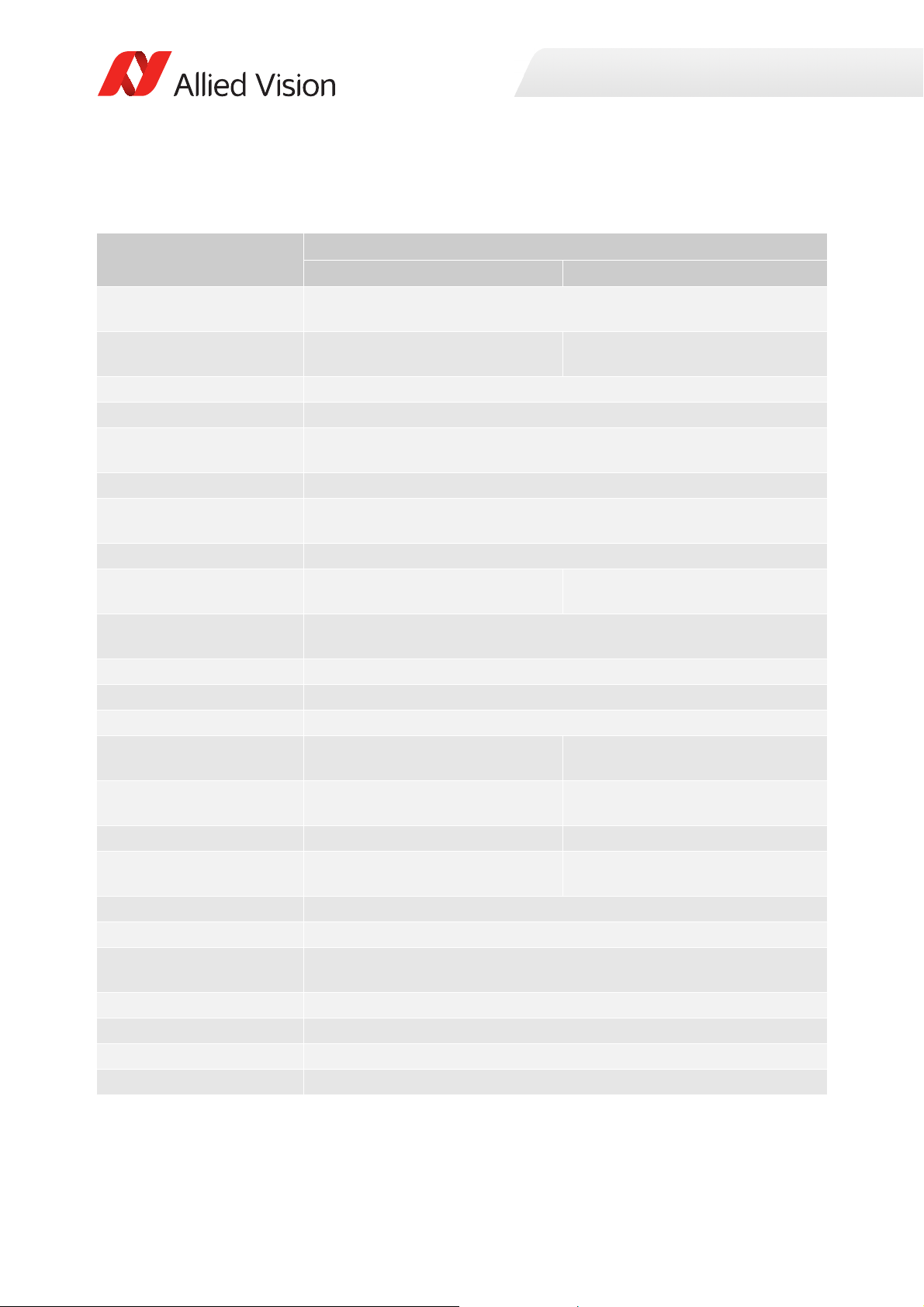
Prosilica GT1290, GT1290C
Specification
Feature
Resolution 1280 (H) × 960 (V)
Sensor Sony ICX445ALA with EXview
HAD CCD™ technology
Sensor type Interline CCD, Progressive Scan
Shutter type Global
Sensor size Type 1/3
Pixel size 3.75 μm × 3.75 μm
Lens mount Standard: C -Mount
Housing Standard format
Optical filter Standard: No optical filter
Optional: See the Modular Concept
Maximum frame rate at full
resolution
Maximum image bit depth 14-bit (monochrome), 12-bit (color)
Image buffer 128 MB
StreamHoldCapacity Up to 53 frames at full resolution
Monochrome formats Mono8, Mono12, Mono12Packed,
Mono14
Color formats (YUV) N/A YUV411Packed, YUV422Packed,
Color formats (RGB) N/A RGB8Packed, BGR8Packed
RAW formats N/A BayerRG8, BayerRG12,
Exposure time control 12 µs to 77.3 s; 1 µs increments
Gain control 0 to 29 dB; 1 dB increments
Binning Horizontal: 1 to 8 columns
Decimation X/Y Horizontal and vertical: 1, 2, 4, 8 factor
Sensor taps Single-tap
TTL (non-isolated) I/Os 1 input, 2 outputs
Opto-isolated I/Os 1 input, 2 outputs
Prosilica GT1290 Prosilica GT1290C
1.2 MP
Sony ICX445AQA with EXview
HAD CCD™ technology
6.0 mm diagonal
Optional: See the Modular Concept
Standard: IRC30 IR cut filter
Optional: See the Modular Concept
33.3 fps
Mono8
YUV444Packed
BayerRG12Packed
Vertical: 1 to 14 rows
Table 4: Prosilica GT1290, GT1290C model specifications
31Prosilica GT Technical Manual V2.9.0
Page 32
Specification
Specifications
Feature
RS232 1 TxD, 1 RxD
Voltage requirements 7 to 25 VDC; PoE
Power consumption 2.9 W @ 12 VDC; 3.5 W PoE
Trigger latency 2 µs
Trigger jitter ±20 ns
Propagation delay (tpd) 30 ns for non-isolated I/O; 70 ns for isolated I/O
Operating temperature -20 °C to +65 °C ambient temperature (without condensation)
Storage temperature -20 °C to +70 °C ambient temperature (without condensation)
Operating humidity 20 to 80% non-condensing
Body dimensions (L × W × H) 86 × 53.3 × 33 mm
Mass (typical) 211 g
Interface IEEE 802.3 1000BASE-T (Gigabit Ethernet), IEEE 802.3af (PoE)
Interface standard GigE Vision® Standard V1.2
Camera control standard GenICam SFNC V1.2.1
Regulations
Temperature monitoring Available for main board and sensor board.
Prosilica GT1290 Prosilica GT1290C
CE, RoHS, REACH, WEEE, FCC, ICES
Resolution: 0.031; Accuracy: ±1 °C
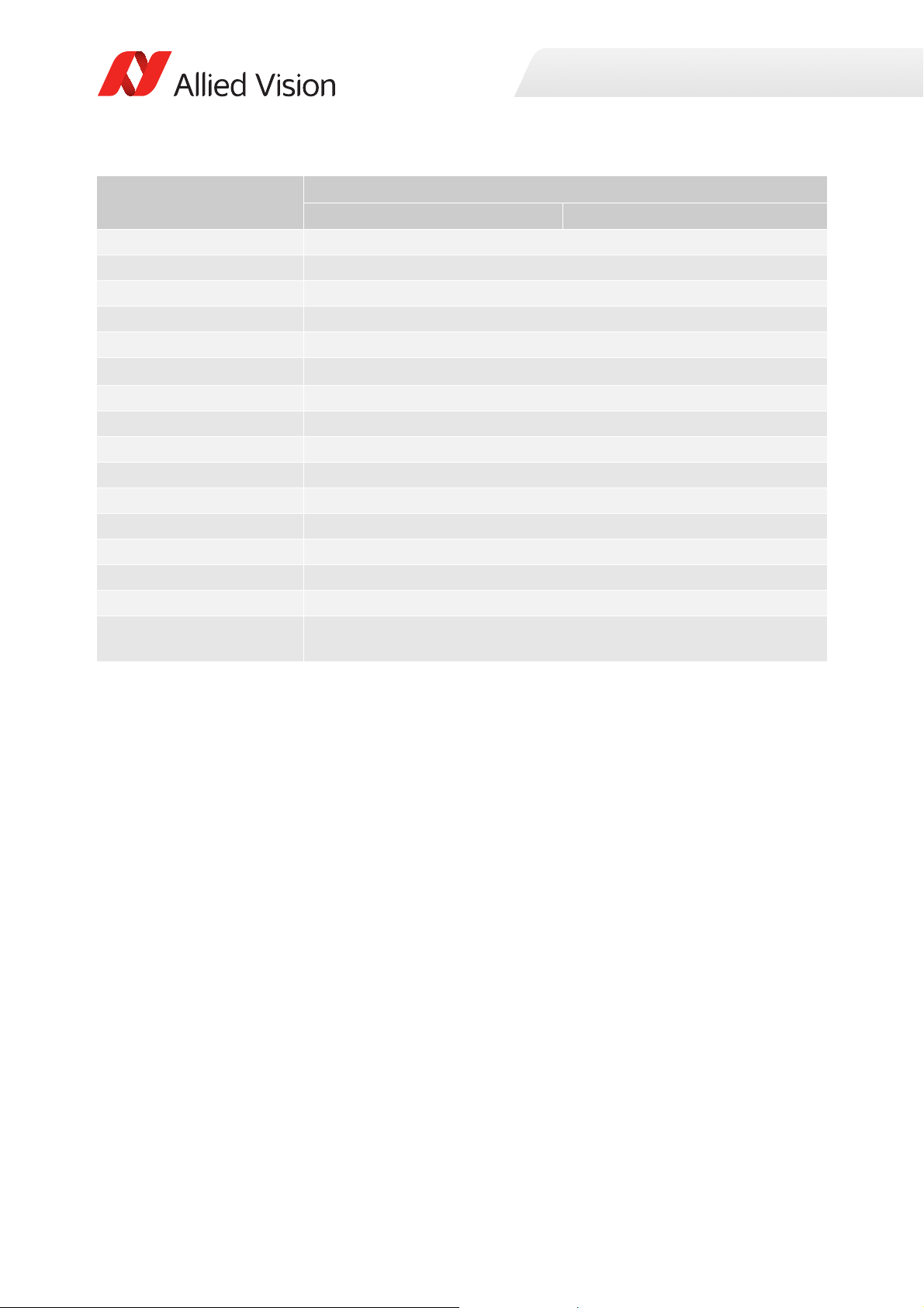
Table 4: Prosilica GT1290, GT1290C model specifications (continued)
32Prosilica GT Technical Manual V2.9.0
Page 33
Absolute QE
0%
10%
20%
30%
40%
50%
60%
400 450 500 550 600 650 700 750 800 850 900 950 1000
QuantumEfficiency[%]
Wavelength[nm]
SonyICX445absoluteQE
AllmeasurementsweredonewithoutprotectionglassorIRcutfilter.
Withprotectionglassorfilters,quantumefficiency(QE)decreasesbyapproximately10%.
TheuncertaintyinmeasurementoftheQEis+/Ͳ 10.25%.
Thevaluesaretypicalandaresubjecttominorvariations.
RedQE GreenQE BlueQE MonochromeQE
0.0000
0.1000
0.2000
0.3000
400 450 500 550 600 650 700 750 800 850 900 950 1000
SpectralResponse[A/W]
Wavelength[nm]
SonyICX445spectralresponse
RedResponse GreenResponse BlueResponse MonochromeResponse
Specifications
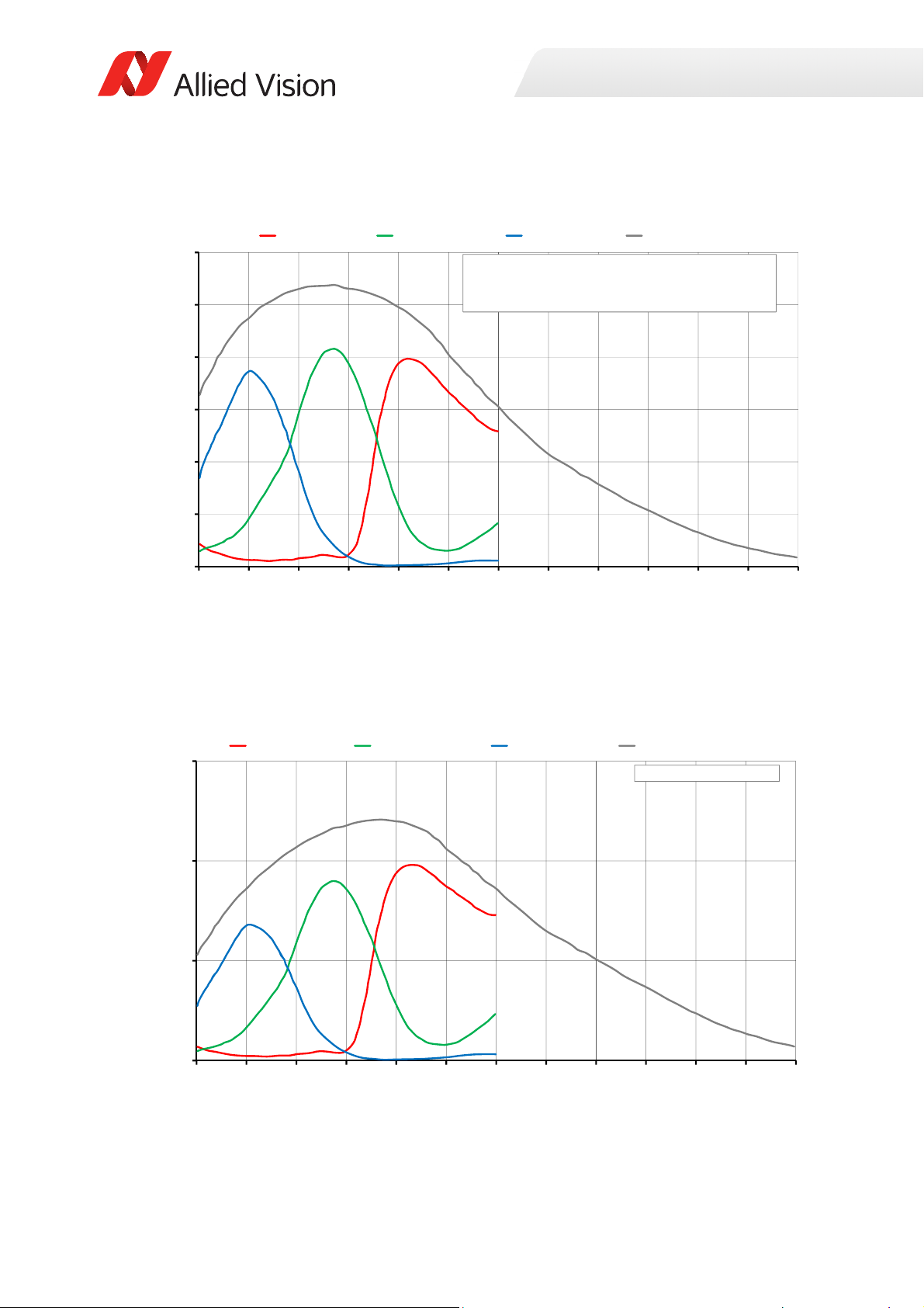
Figure 1: Prosilica GT1290, GT1290C (Sony ICX445) absolute QE
Spectral response
Figure 2: Prosilica GT1290, GT1290C (Sony ICX445) spectral response
33Prosilica GT Technical Manual V2.9.0
Page 34
ROI frame rate
20
60
100
140
180
220
260
300
340
0 100 200 300 400 500 600 700 800 900 1000
Framerate[fps]
ROIheight[pixels]
Specifications
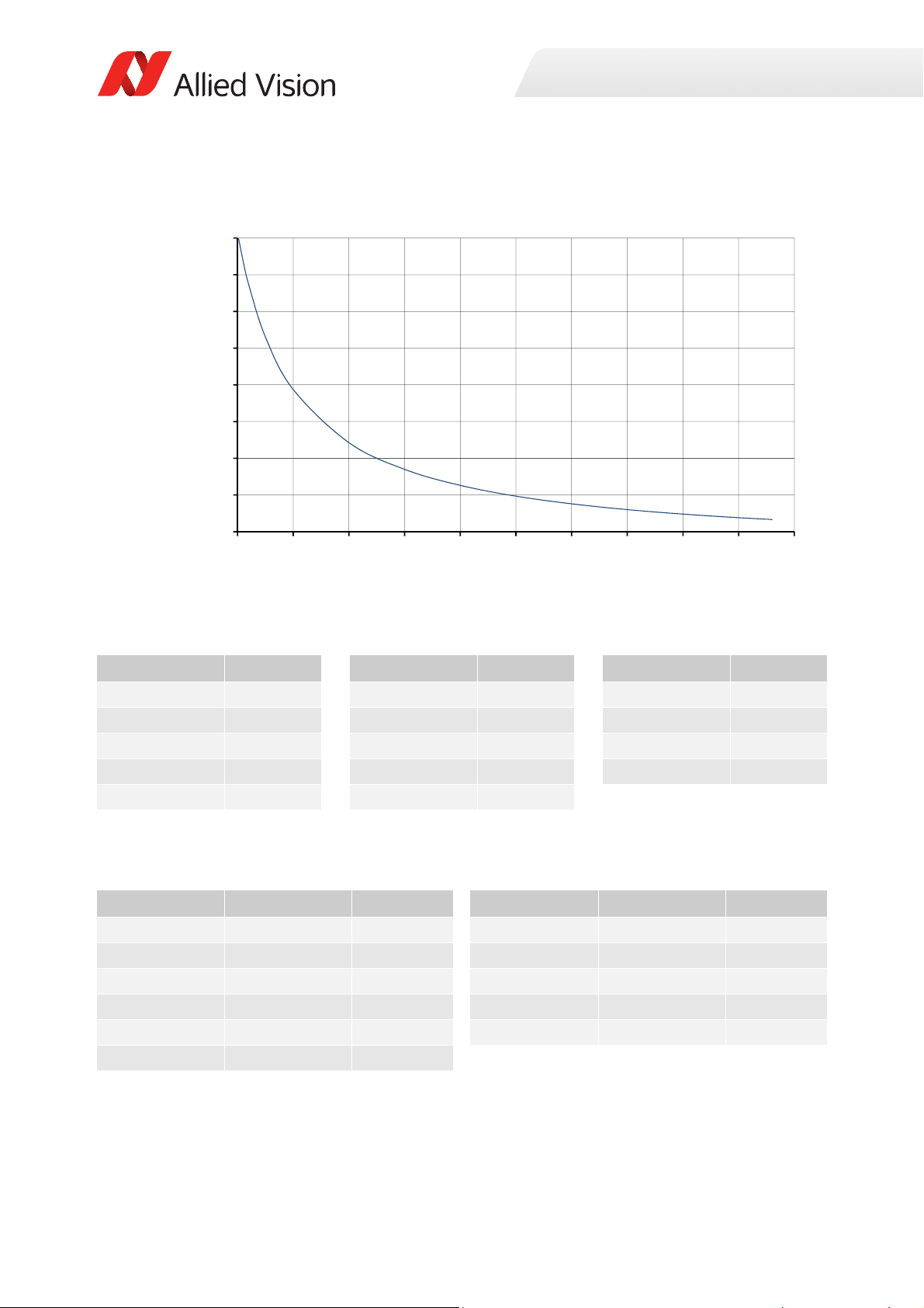
Figure 3: Frame rate as a function of ROI height [width=1280 pixels]
Height in pixels Frame rate Height in pixels Frame rate Height in pixels Frame rate
960 33.3 500 58.8 50 232.4
900 35.3 400 70.5 20 289.5
800 39.2 300 88 10 315.2
700 44.1 200 117.1 2 339.4
600 50.4 100 175
Table 5: Frame rate as a function of ROI height [width=1280 pixels]
The following table shows how binning affects frame rate.
BinningVertical Height in pixels Frame rate BinningVertical Height in pixels Frame rate
2 480 60.8 8 120 158.3
3 320 83.8 9 106 168.7
4 240 103.3 10 96 176.9
5 192 120 11 86 185.1
6 160 134.5 12 80 191.9
7 136 147.8
Table 6: Frame rate as a function of ROI height with vertical binning enabled
34Prosilica GT Technical Manual V2.9.0
Page 35
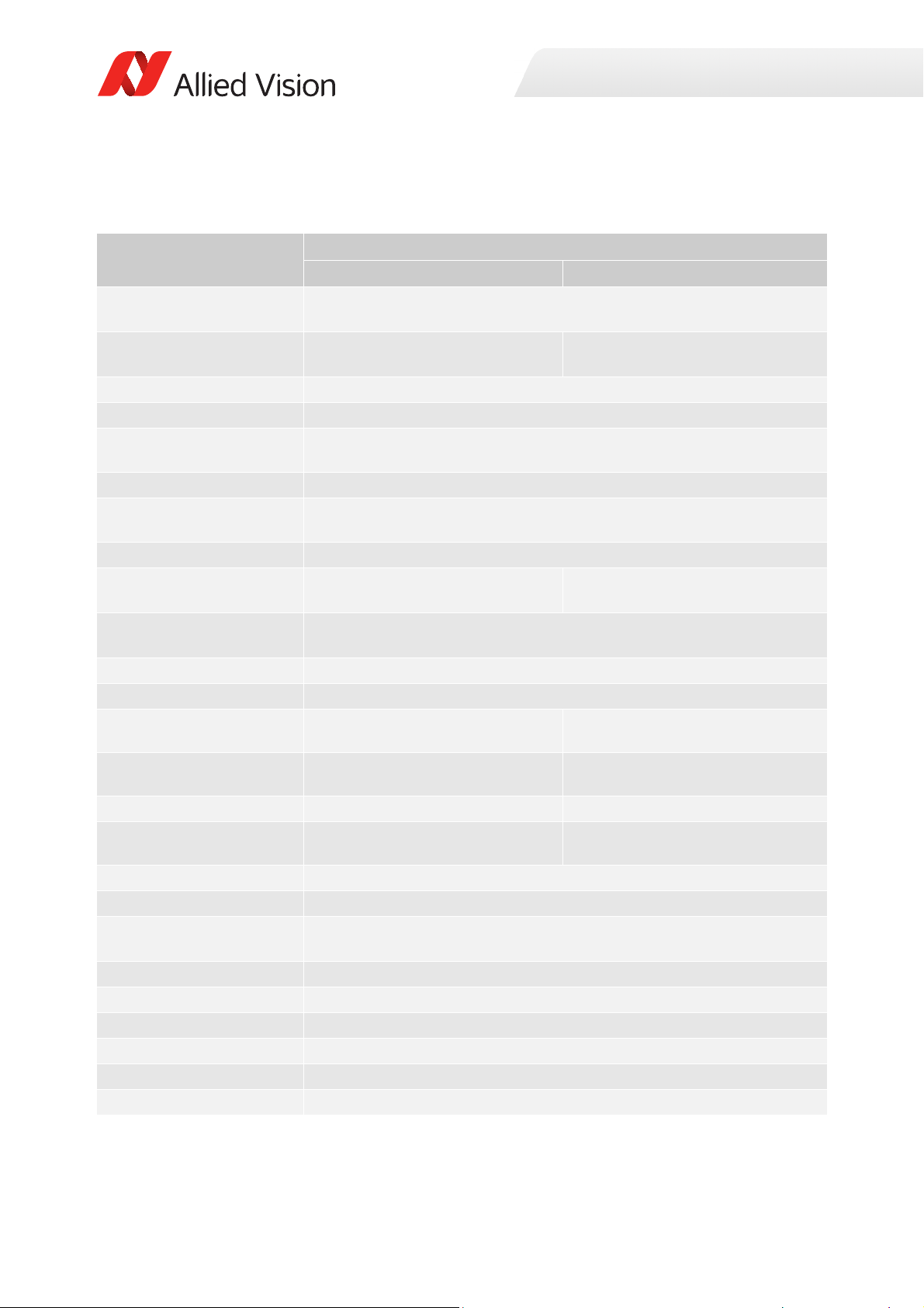
Prosilica GT1380, GT1380C
Specification
Feature
Resolution 1360 (H) × 1024 (V)
Sensor Sony ICX285AL with EXview
HAD CCD™ technology
Sensor type
Shutter type Global
Sensor size
Pixel size 6.45 μm × 6.45 μm
Lens mount
Housing Standard format
Optical filter Standard: No optical filter
Optional: See the Modular Concept
Maximum frame rate at full
resolution
Maximum image bit depth
Image buffer
Monochrome formats
Color formats (YUV) N/A
Color formats (RGB) N/A
RAW formats N/A
Exposure time control
Gain control
Binning Horizontal: 1 to 8 columns
Decimation X/Y Horizontal and vertical: 1, 2, 4, 8 factor
Sensor taps Single-tap
TTL (non-isolated) I/Os
Opto-isolated I/Os
RS232
Voltage requirements
Mono8, Mono12, Mono12Packed,
Mono14
Prosilica GT1380 Prosilica GT1380C
1.4 MP
Sony ICX285AQ with EXview
HAD CCD™ technology
Interline CCD, Progressive Scan
Typ e 2/3
11.0 mm
Standard: C-Mount
Optional: See the
14-bit (monochrome), 12-bit (color)
10 µs to 77.3 s; 1 µs increments
0 to 34 dB; 1 dB increments
Vertical: 1 to 14 rows
1 input, 2 outputs
1 input, 2 outputs
7 to 25 VDC; PoE
diagonal
Modular Concept
Standard: IRC30 IR cut filter
Optional: See the Modular Concept
30.5 fps
128 MB
Mono8
YUV411Packed, YUV422Packed,
YUV444Packed
RGB8Packed, BGR8Packed
BayerRG8, BayerRG12,
BayerRG12Packed
1 TxD, 1 RxD
Specifications
Table 7: Prosilica GT1380, GT1380C model specifications
35Prosilica GT Technical Manual V2.9.0
Page 36
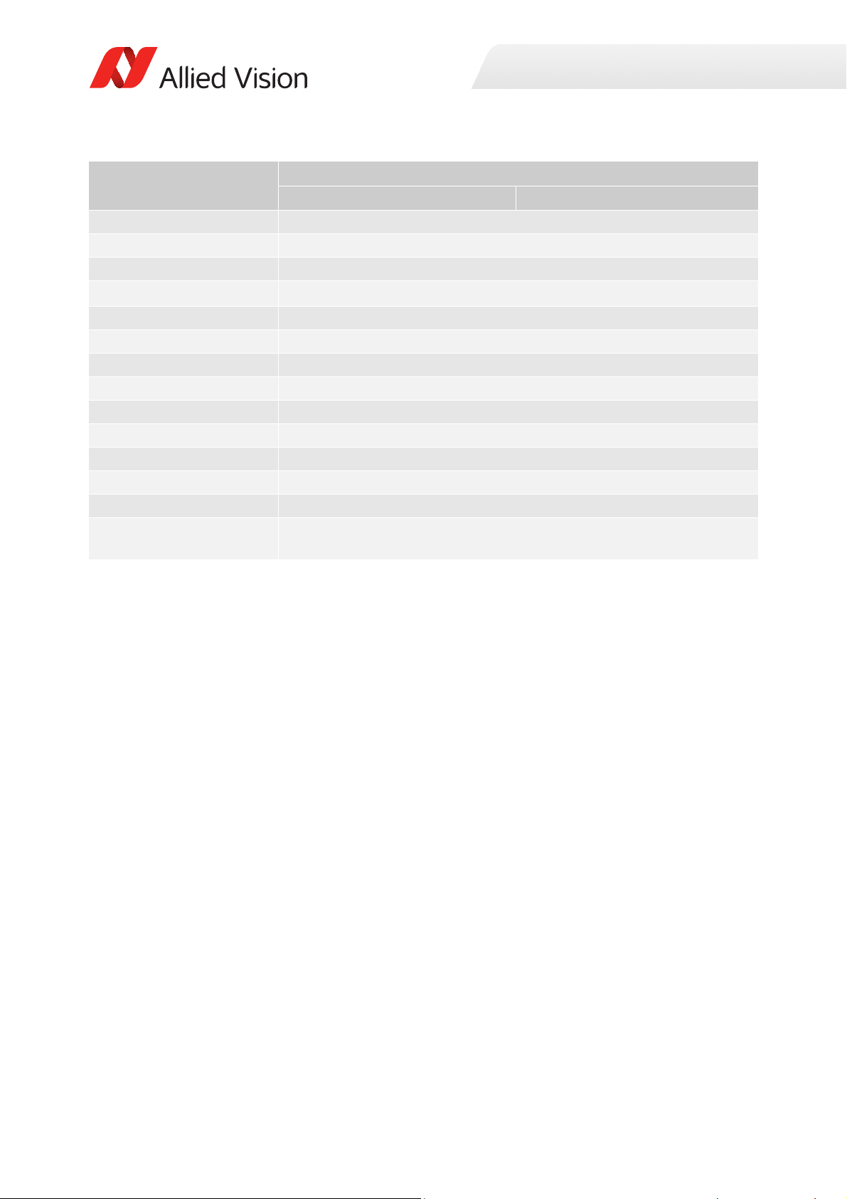
Specification
Specifications
Feature
Power consumption
Trigger latency
Prosilica GT1380 Prosilica GT1380C
3.4 W @ 12 VDC; 4.2 W PoE
2.2 µs
Trigger jitter ±20 ns
Propagation delay (tpd)
Operating temperature
Storage temperature
Operating humidity
Body dimensions (L × W × H)
Mass (typical)
Interface
Interface standard
30 ns for non-isolated I/O; 70 ns for isolated I/O
-20 °C to +65 °C ambient temperature (without condensation)
-20 °C to +70 °C ambient temperature (without condensation)
20 to 80% non-condensing
86 × 53.3 × 33 mm
211 g
IEEE 802.3 1000BASE-T (Gigabit Ethernet), IEEE 802.3af (PoE)
GigE Vision® Standard V1.2
Camera control standard GenICam SFNC V1.2.1
Regulations
CE, RoHS, REACH, WEEE, FCC, ICES
Temperature monitoring Available for main board and sensor board.
Resolution: 0.031; Accuracy: ±1 °C
Table 7: Prosilica GT1380, GT1380C model specifications (continued)
36Prosilica GT Technical Manual V2.9.0
Page 37
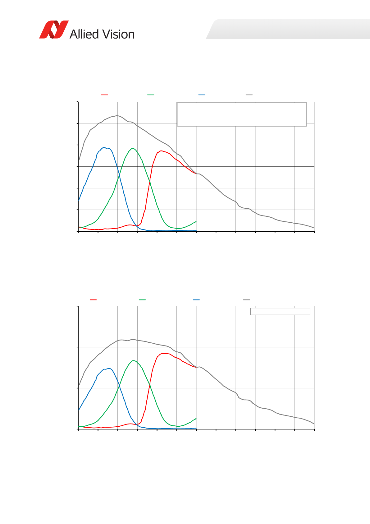
Absolute QE
0%
10%
20%
30%
40%
50%
60%
400 450 500 550 600 650 700 750 800 850 900 950 1000
QuantumEfficiency[%]
Wavelength[nm]
SonyICX285absoluteQE
AllmeasurementsweredonewithoutprotectionglassorIRcutfilter.
Withprotectionglassorfilters,quantumefficiency(QE)decreasesbyapproximately10%.
TheuncertaintyinmeasurementoftheQEis+/Ͳ 10.25%.
Thevaluesaretypicalandaresubjecttominorvariations.
RedQE GreenQE BlueQE MonochromeQE
0.0000
0.1000
0.2000
0.3000
400 450 500 550 600 650 700 750 800 850 900 950 1000
SpectralResponse[A/W]
Wavelength[nm]
SonyICX285spectralresponse
RedResponse GreenResponse BlueResponse MonochromeResponse
Specifications
Figure 4: Prosilica GT1380, GT1380C (Sony ICX285) absolute QE
Spectral response
Figure 5: Prosilica GT1380, GT1380C (Sony ICX285) spectral response
37Prosilica GT Technical Manual V2.9.0
Page 38
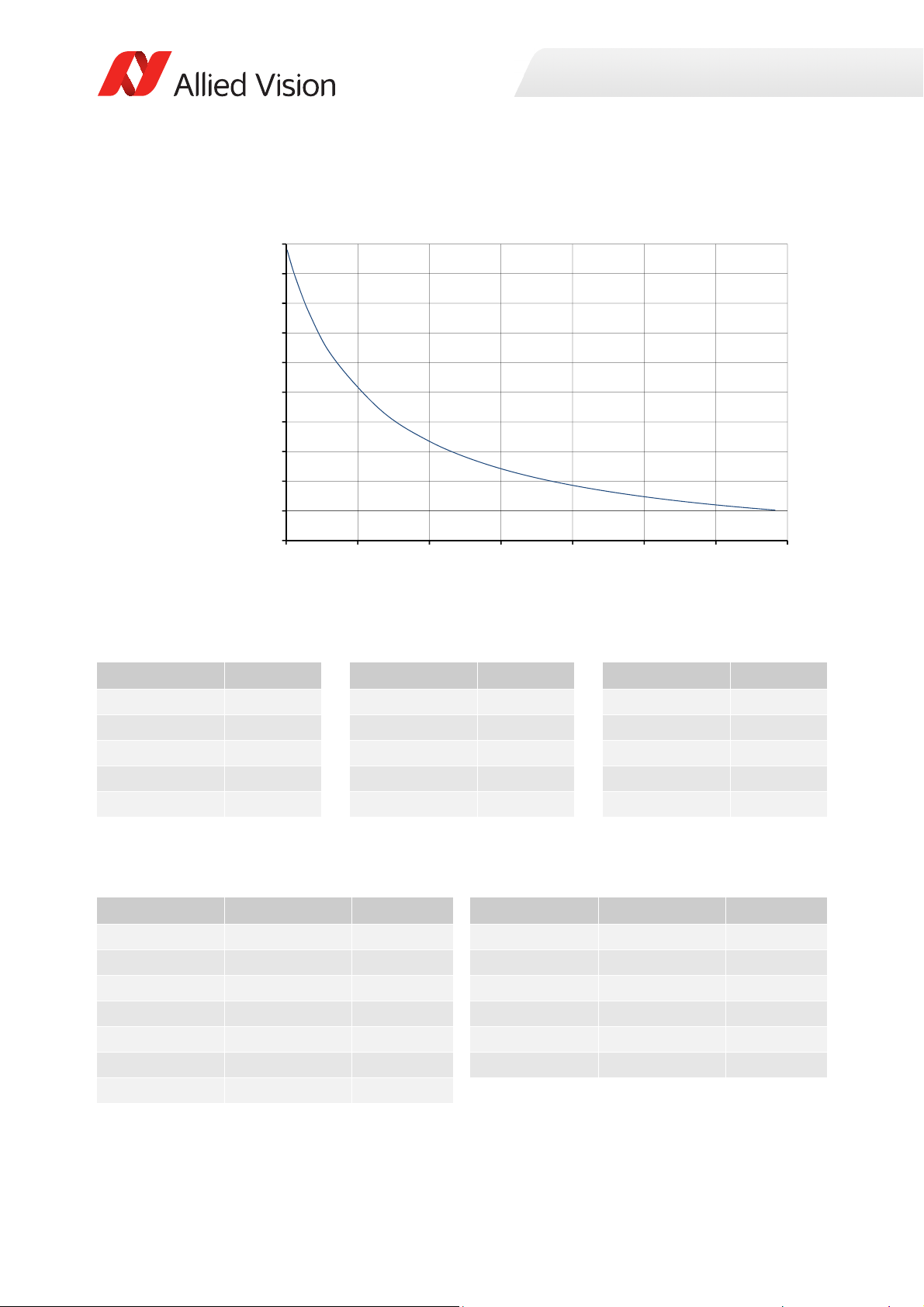
ROI frame rate
10
30
50
70
90
110
130
150
170
190
210
0 150 300 450 600 750 900 1050
Framerate[fps]
ROIheight[pixels]
Specifications
Figure 6: Frame rate as a function of ROI height [width=1360 pixels]
Height in pixels Frame rate Height in pixels Frame rate Height in pixels Frame rate
1024 30.5 600 47.2 100 132.7
1000 31.1 500 54.1 50 162.1
900 34 400 63.5 20 186.9
800 37.5 300 76.9 10 197
700 41.8 200 97.4 2 205.9
Table 8: Frame rate as a function of ROI height [width=1360 pixels]
The following table shows how binning affects frame rate.
BinningVertical Height in pixels Frame rate BinningVertical Height in pixels Frame rate
2 512 53.2 9 113 125.6
3 341 70.7 10 102 130.4
4 256 84.6 11 93 134.6
5 204 96.0 12 85 138.5
6 170 105.4 13 78 142.1
7 146 113.1 14 73 144.7
8 128 119.6
Table 9: Frame rate as a function of ROI height with vertical binning enabled
38Prosilica GT Technical Manual V2.9.0
Page 39
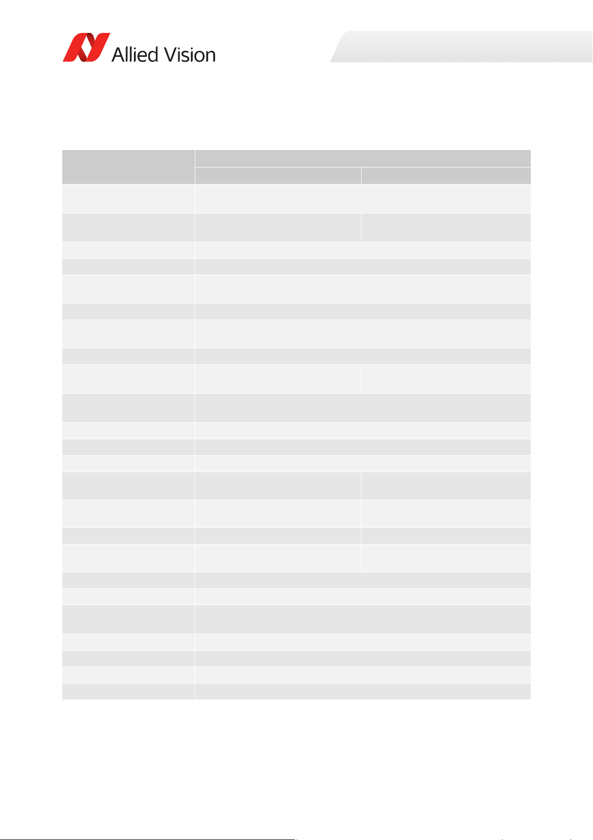
Prosilica GT1600, GT1600C
Specification
Feature
Resolution 1620 (H) × 1220 (V)
Sensor Sony ICX274AL with Super HAD
CCD™ technology
Sensor type
Shutter type Global
Sensor size
Pixel size 4.4 μm × 4.4 μm
Lens mount
Housing Standard format
Optical filter Standard: No optical filter
Optional: See the Modular Concept
Maximum frame rate at full
resolution
Maximum image bit depth
Image buffer
StreamHoldCapacity
Monochrome formats
Color formats (YUV) N/A
Color formats (RGB) N/A
RAW formats N/A
Exposure time control
Gain control
Binning Horizontal: 1 to 8 columns
Decimation X/Y Horizontal and vertical: 1, 2, 4, 8 factor
Sensor taps Single-tap
TTL (non-isolated) I/Os
Opto-isolated I/Os
Mono8, Mono12, Mono12Packed,
Mono14
Prosilica GT1600 Prosilica GT1600C
2 MP
Sony ICX274AQ with Super HAD
Wfine CCD™ technology
Interline CCD, Progressive Scan
Type 1/1.8
8.923 mm diagonal
Standard: C-Mount
Optional: See the
14-bit (monochrome), 12-bit (color)
Up to 33 frames at full resolution
10 µs to 68.7 s, 1 µs increments
0 to 26 dB; 1 dB increments
Vertical: 1 to 14 rows
1 input, 2 outputs
1 input, 2 outputs
Modular Concept
Standard: IRC30 IR cut filter
Optional: See the Modular Concept
25.8 fps
128 MB
Mono8
YUV411Packed, YUV422Packed,
YUV444Packed
RGB8Packed, BGR8Packed
BayerRG8, BayerRG12,
BayerRG12Packed
Specifications
Table 10: Prosilica GT1600, GT1600C model specifications
39Prosilica GT Technical Manual V2.9.0
Page 40
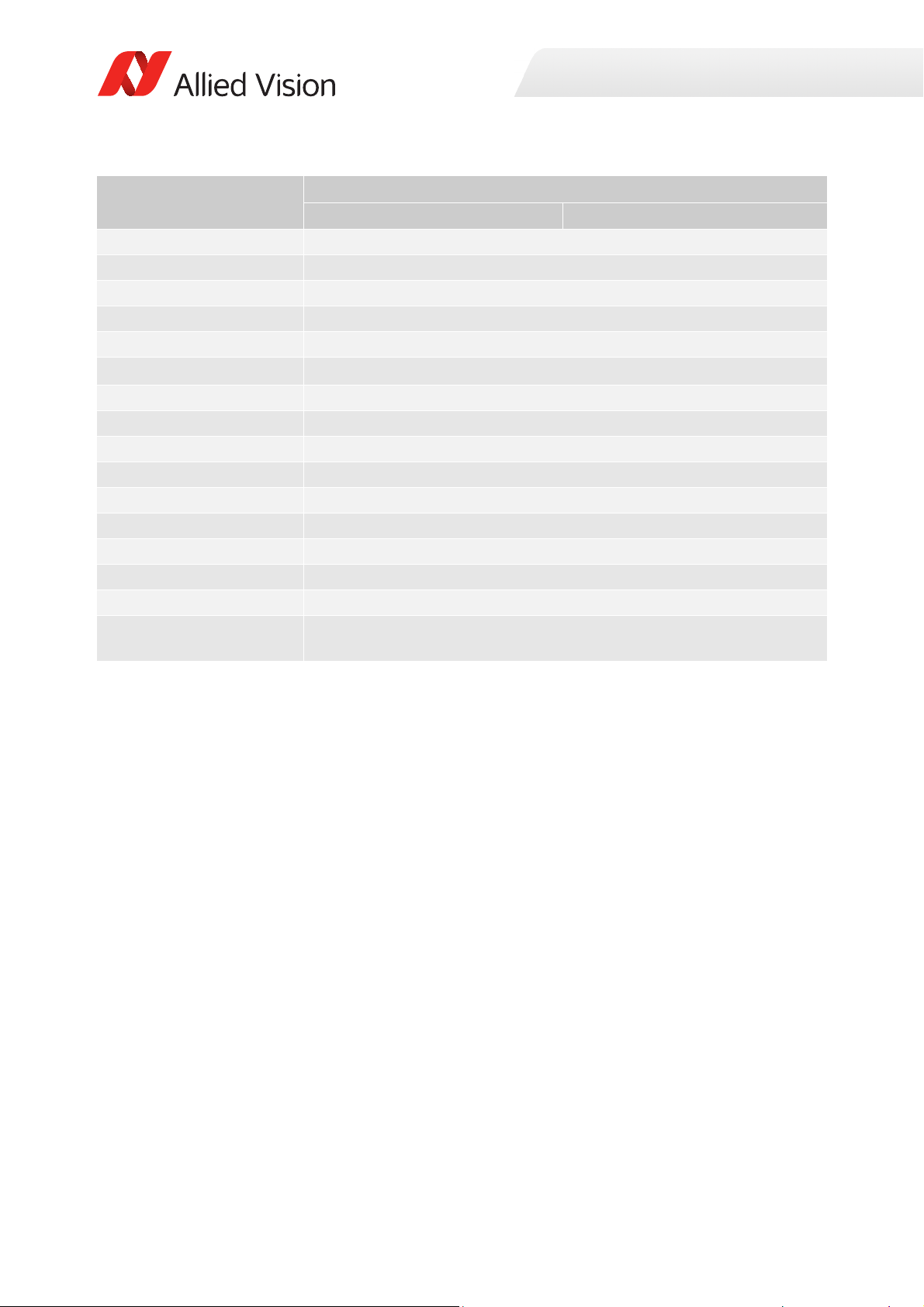
Specification
Specifications
Feature
RS232
Voltage requirements
Power consumption
Trigger latency
Prosilica GT1600 Prosilica GT1600C
1 TxD, 1 RxD
7 to 25 VDC; PoE
3.3 W @ 12 VDC; 4.0 W PoE
1.4 µs
Trigger jitter ±20 ns
Propagation delay (tpd)
Operating temperature
Storage temperature
Operating humidity
Body dimensions (L × W × H)
Mass (typical)
Interface
Interface standard
30 ns for non-isolated I/O; 70 ns for isolated I/O
-20 °C to +65 °C ambient temperature (without condensation)
-20 °C to +70 °C ambient temperature (without condensation)
20 to 80% non-condensing
86 × 53.3 × 33 mm
211 g
IEEE 802.3 1000BASE-T (Gigabit Ethernet), IEEE 802.3af (PoE)
GigE Vision® Standard V1.2
Camera control standard GenICam SFNC V1.2.1
Regulations
CE, RoHS, REACH, WEEE, FCC, ICES
Temperature monitoring Available for main board and sensor board.
Resolution: 0.031; Accuracy: ±1 °C
Table 10: Prosilica GT1600, GT1600C model specifications (continued)
40Prosilica GT Technical Manual V2.9.0
Page 41
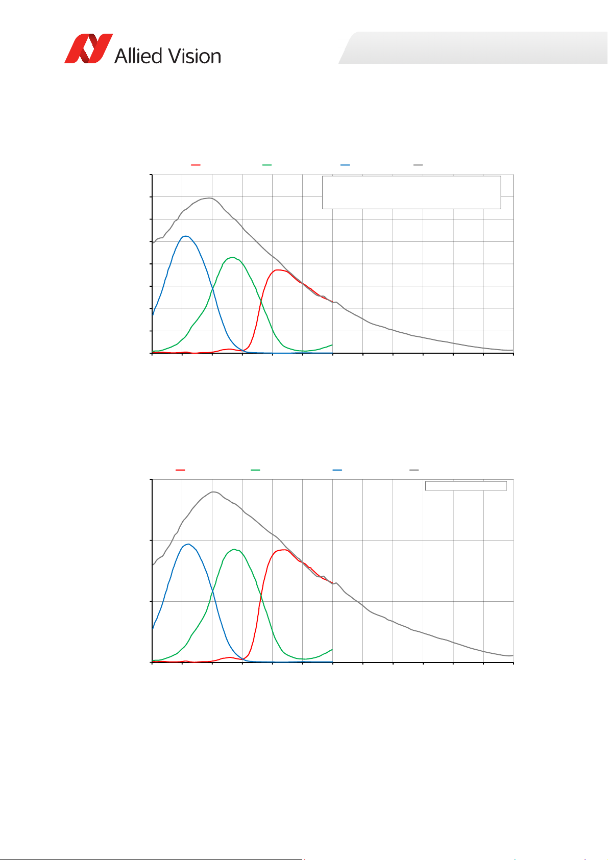
Absolute QE
0%
10%
20%
30%
40%
50%
60%
70%
80%
400 450 500 550 600 650 700 750 800 850 900 950 1000
QuantumEfficiency[%]
Wavelength[nm]
SonyICX274absoluteQE
AllmeasurementsweredonewithoutprotectionglassorIRcutfilter.
Withprotectionglassorfilters,quantumefficiency(QE)decreasesbyapproximately10%.
TheuncertaintyinmeasurementoftheQEis+/Ͳ 10.25%.
Thevaluesaretypicalandaresubjecttominorvariations.
RedQE GreenQE BlueQE MonochromeQE
0.0000
0.1000
0.2000
0.3000
400 450 500 550 600 650 700 750 800 850 900 950 1000
SpectralResponse[A/W]
Wavel ength[nm]
SonyICX274spectralresponse
RedResponse GreenResponse BlueResponse MonochromeResponse
Specifications
Figure 7: Prosilica GT1600, GT1600C (Sony ICX274) absolute QE
Spectral response
Figure 8: Prosilica GT1600, GT1600C (Sony ICX274) spectral response
41Prosilica GT Technical Manual V2.9.0
Page 42
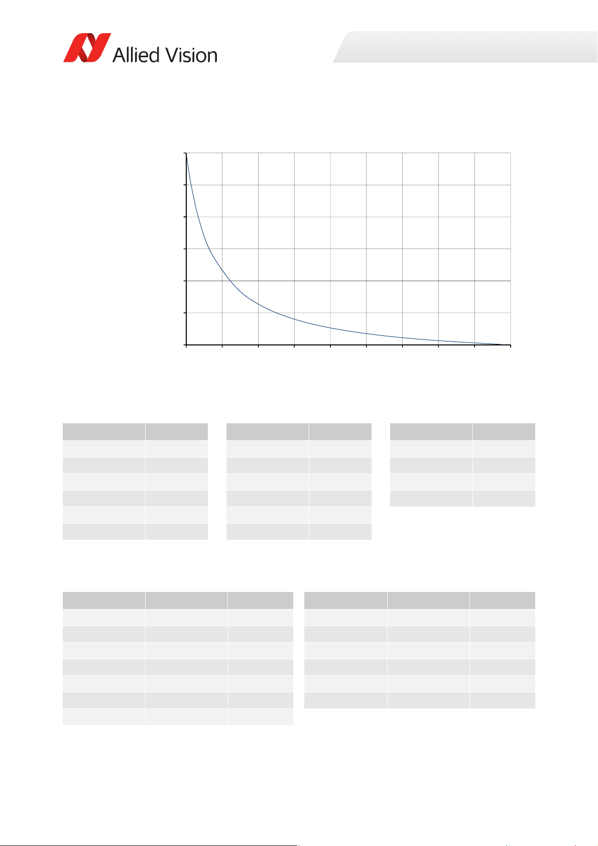
ROI frame rate
25
75
125
175
225
275
325
0 140 280 420 560 700 840 980 1120 1260
Framerate[fps]
ROIheight[pixels]
Specifications
Figure 9: Frame rate as a function of ROI height [width=1620 pixels]
Height in pixels Frame rate Height in pixels Frame rate Height in pixels Frame rate
1220 25.8 600 48.5 50 220.2
1100 28.4 500 56.5 20 272.9
1000 31 400 67.7 10 296.5
900 34 300 84.4 2 318.6
800 37.8 200 112.1
700 42.5 100 116.6
Table 11: Frame rate as a function of ROI height [width=1620 pixels]
The following table shows how binning affects frame rate.
BinningVertical Height in pixels Frame rate BinningVertical Height in pixels Frame rate
2 610 47.9 9 134 142.2
3 406 66.9 10 122 149.6
4 304 83.5 11 110 157.7
5 244 97.8 12 100 165.2
6 202 111.0 13 92 171.7
7 174 122.1 14 86 176.9
8 152 132.4
Table 12: Frame rate as a function of ROI height with vertical binning enabled
42Prosilica GT Technical Manual V2.9.0
Page 43
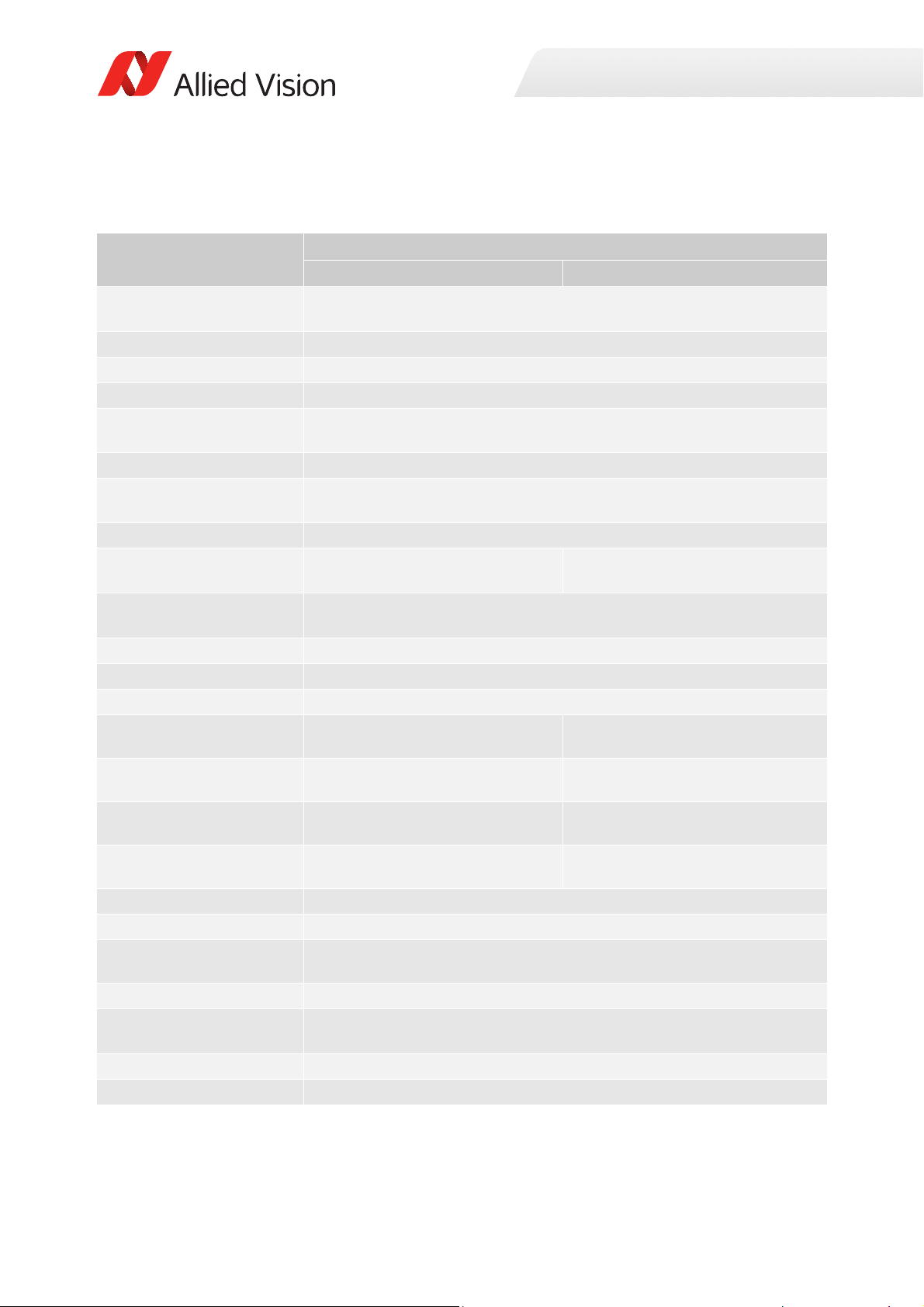
Prosilica GT1660, GT1660C
Specification
Feature
Resolution 1600 (H) × 1200 (V)
Sensor ON Semi KAI-02050 TRUESENSE Gen 2
Sensor type
Shutter type Global
Sensor size
Pixel size 5.5 μm × 5.5 μm
Lens mount
Housing Extended format
Optical filter Standard: No optical filter
Optional: See the Modular Concept
Maximum frame rate at full
resolution
Maximum image bit depth
Image buffer
StreamHoldCapacity
Monochrome formats
Color formats (YUV)
Color formats (RGB)
RAW formats
Exposure time control
Gain control
Binning
Decimation X/Y Horizontal and vertical: 1, 2, 4, 8 factor
Sensor taps Four-tap
TTL (non-isolated) I/Os
Opto-isolated I/Os
Mono8, Mono12, Mono12Packed,
Mono14
N/A YUV411Packed, YUV422Packed,
N/A RGB8Packed, BGR8Packed,
N/A BayerGR8, BayerGR12,
Prosilica GT1660 Prosilica GT1660C
1.9 MP
Interline CCD, Progressive Scan
Typ e 2/3
11.0 mm
Standard: C-Mount
Optional: See the
Four-tap mode: 62.1 fps
One-tap mode: 17.9 fps
14-bit (monochrome), 12-bit (color)
Up to 68 frames at full resolution
10 µs to 26.8 s, 1 µs increments
0 to 32 dB; 1 dB increments
Horizontal: 1 to 8 columns
Vertical: 1 to 8 rows
Single-tap switchable in Vimba Viewer 2.0 or later
1 input, 2 outputs
1 input, 2 outputs
diagonal
Modular Concept
Standard: IRC30 IR cut filter
Optional: See the Modular Concept
128 MB
Mono8
YUV444Packed
RGBA8Packed, BGRA8Packed
BayerRG12Packed
Specifications
Table 13: Prosilica GT1660, GT1660C model specifications
43Prosilica GT Technical Manual V2.9.0
Page 44
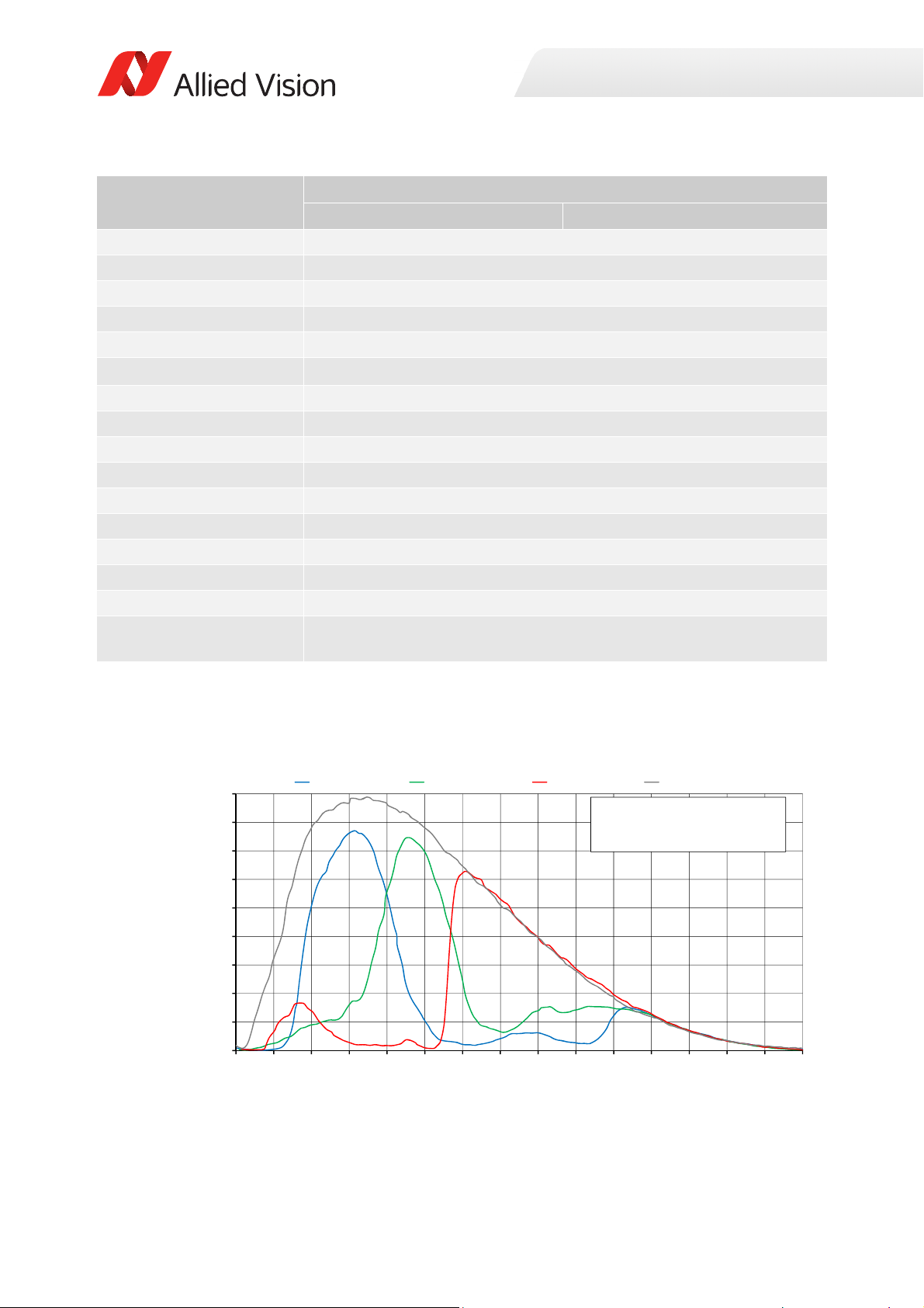
Specification
0%
5%
10%
15%
20%
25%
30%
35%
40%
45%
300 350 400 450 500 550 600 650 700 750 800 850 900 950 1000 1050
QuantumEfficiency
Wavelen gth[nm]
ONSemiconductorKAIͲ02050absoluteQE
ONSemiconductorGen2CFAmaterialforcolorsensors
Note:MeasuredwithARcoatedcoverglass.
TheuncertaintyinmeasurementoftheQEis+/Ͳ 10.25%.
Thevaluesaretypicalandaresubjecttominorvariations.
BlueQE GreenQE RedQE MonochromeQE
Specifications
Feature
RS232
Voltage requirements
Power consumption
Trigger latency
Prosilica GT1660 Prosilica GT1660C
1 TxD, 1 RxD
7 to 25 VDC; PoE
5.1 W @ 12 VDC; 6.3 W PoE
2.1 µs
Trigger jitter ±20 ns
Propagation delay (tpd)
Operating temperature
Storage temperature
Operating humidity
Body dimensions (L × W × H)
Mass (typical)
Interface
Interface standard
30 ns for non-isolated I/O; 70 ns for isolated I/O
-20 °C to +60 °C ambient temperature (without condensation)
-20 °C to +70 °C ambient temperature (without condensation)
20 to 80% non-condensing
92 × 53.3 × 33 mm
224 g
IEEE 802.3 1000BASE-T (Gigabit Ethernet), IEEE 802.3af (PoE)
GigE Vision® Standard V1.2
Camera control standard GenICam SFNC V1.2.1
Regulations
CE, RoHS, REACH, WEEE, FCC, ICES
Temperature monitoring Available for main board and sensor board.
Resolution: 0.031; Accuracy: ±1 °C
Table 13: Prosilica GT1660, GT1660C model specifications (continued)
Absolute QE
Figure 10: Prosilica GT1660, GT1660C (ON Semi KAI-02050 Gen 2) absolute QE
44Prosilica GT Technical Manual V2.9.0
Page 45
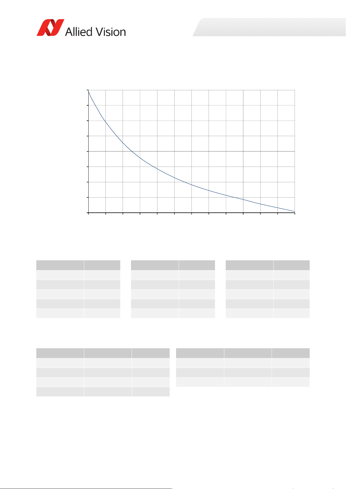
ROI frame rate
60
85
110
135
160
185
210
235
260
0 100 200 300 400 500 600 700 800 900 1000 1100 1200
Framerate[fps]
ROIheight[pixels]
Specifications
Figure 11: Frame rate as function of ROI height [width=1600 pixels]
Height in pixels Frame rate Height in pixels Frame rate Height in pixels Frame rate
1200 62.1 600 105.6 100 207.8
1000 74.3 500 117.2 50 230.2
900 81.6 400 131.6 20 245.3
800 88.4 300 149.4 10 250.8
700 96.3 200 174 2 256.5
Table 14: Frame rate as a function of ROI height [width=1600 pixels]
The following table shows how binning affects frame rate.
BinningVertical Height in pixels Frame rate BinningVertical Height in pixels Frame rate
2 600 121 6 200 260.8
3 400 165.4 7 170 284.0
4 300 202.8 8 150 303.1
5 240 234.2
Table 15: Frame rate as a function of ROI height with vertical binning enabled
45Prosilica GT Technical Manual V2.9.0
Page 46
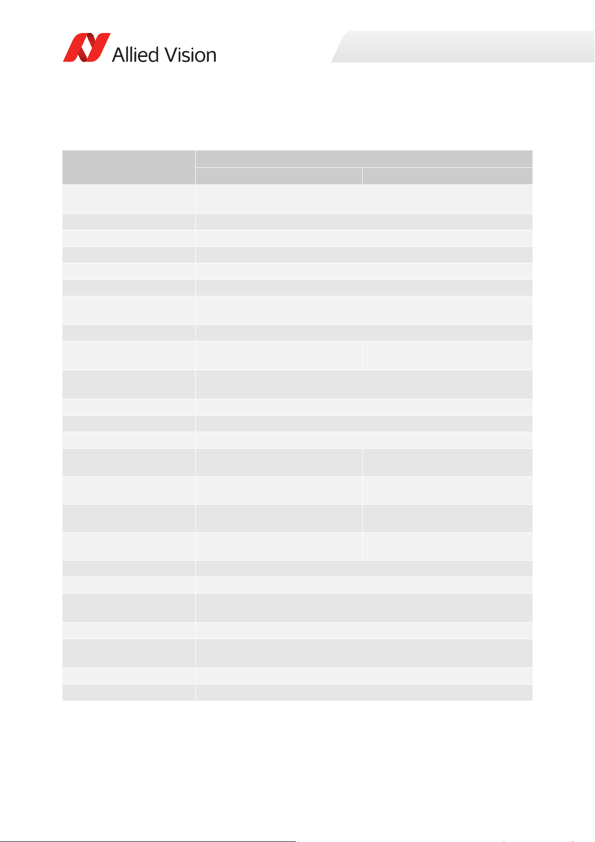
Prosilica GT1910, GT1910C
Specification
Feature
Resolution 1920 (H) × 1080 (V)
Sensor ON Semi KAI-02150 TRUESENSE Gen 2
Sensor type
Shutter type Global
Sensor size Type 2/3; 12.1 mm diagonal
Pixel size 5.5 μm × 5.5 μm
Lens mount
Housing Extended format
Optical filter Standard: No optical filter
Optional: See the Modular Concept
Maximum frame rate at full
resolution
Maximum image bit depth
Image buffer
StreamHoldCapacity
Monochrome formats
Color formats (YUV)
Color formats (RGB)
RAW formats
Exposure time control
Gain control
Binning Horizontal: 1 to 8 columns
Decimation X/Y Horizontal and vertical: 1, 2, 4, 8 factor
Sensor taps Four-tap
TTL (non-isolated) I/Os
Opto-isolated I/Os
Mono8, Mono12, Mono12Packed,
Mono14
N/A YUV411Packed, YUV422Packed,
N/A RGB8Packed, BGR8Packed,
N/A BayerGR8, BayerGR12,
Prosilica GT1910 Prosilica GT1910C
2.1 MP
Interline CCD, Progressive Scan
Standard: C-Mount
Optional: See the
Four-tap mode: 57.5 fps
One-tap mode: 16.9 fps
14-bit (monochrome), 12-bit (color)
Up to 63 frames at full resolution
10 µs to 26.8 s, 1 µs increments
0 to 32 dB; 1 dB increments
Vertical: 1 to 8 rows
Single-tap switchable in Vimba Viewer 2.0 or later
1 input, 2 outputs
1 input, 2 outputs
Modular Concept
Standard: IRC30 IR cut filter
Optional: See the Modular Concept
128 MB
Mono8
YUV444Packed
RGBA8Packed, BGRA8Packed
BayerRG12Packed
Specifications
Table 16: Prosilica GT1910, GT1910C model specifications
46Prosilica GT Technical Manual V2.9.0
Page 47
Specification
Specifications
Feature
RS232
Voltage requirements
Power consumption
Trigger latency
Prosilica GT1910 Prosilica GT1910C
1 TxD, 1 RxD
7 to 25 VDC; PoE
5.1 W @ 12 VDC; 6.3 W PoE
2.2 µs
Trigger jitter ±20 ns
Propagation delay (tpd)
Operating temperature
Storage temperature
Operating humidity
Body dimensions (L × W × H)
Mass (typical)
Interface
Interface standard
30 ns for non-isolated I/O; 70 ns for isolated I/O
-20 °C to +60 °C ambient temperature (without condensation)
-20 °C to +70 °C ambient temperature (without condensation)
20 to 80% non-condensing
92 × 53.3 × 33 mm
224 g
IEEE 802.3 1000BASE-T (Gigabit Ethernet), IEEE 802.3af (PoE)
GigE Vision® Standard V1.2
Camera control standard GenICam SFNC V1.2.1
Regulations
CE, RoHS, REACH, WEEE, FCC, ICES
Temperature monitoring Available for main board and sensor board.
Resolution: 0.031; Accuracy: ±1 °C
Table 16: Prosilica GT1910, GT1910C model specifications (continued)
47Prosilica GT Technical Manual V2.9.0
Page 48
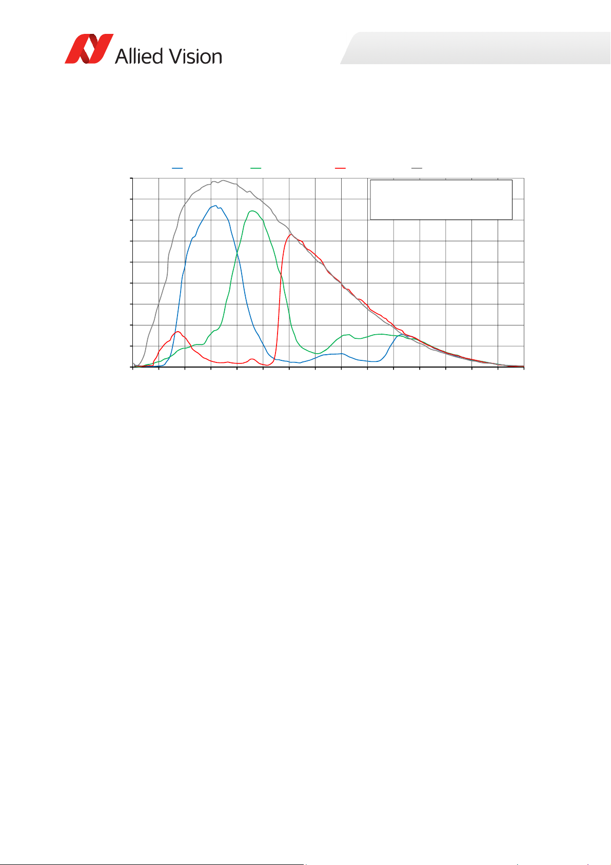
Absolute QE
0%
5%
10%
15%
20%
25%
30%
35%
40%
45%
300 350 400 450 500 550 600 650 700 750 800 850 900 950 1000 1050
QuantumEfficiency
Wavelength[nm]
ONSemiconductorKAIͲ02150absoluteQE
ONSemiconductorGen2CFAmaterialforcolorsensors
Note:MeasuredwithARcoatedcoverglass.
TheuncertaintyofmeasurementoftheQEis+/Ͳ 10.25%.
Thevaluesaretypicalandaresubjecttominorvariations.
BlueQE GreenQE RedQE MonochromeQE
Specifications
Figure 12: Prosilica GT1910, GT1910C (ON Semi KAI-02150 Gen 2) absolute QE
48Prosilica GT Technical Manual V2.9.0
Page 49
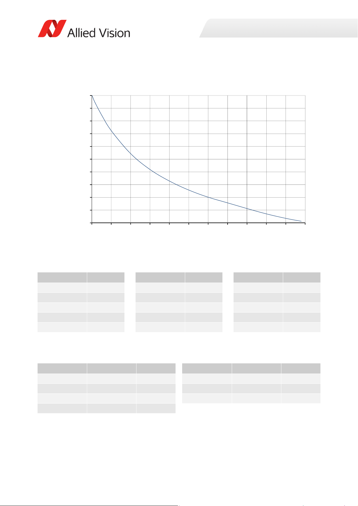
ROI frame rate
55
75
95
115
135
155
175
195
215
235
255
0 100 200 300 400 500 600 700 800 900 1000 1100
Framerate[fps]
ROIheight[pixels]
Specifications
Figure 13: Frame rate as a function of ROI height [width=1920 pixels]
Height in pixels Frame rate Height in pixels Frame rate Height in pixels Frame rate
1080 57.5 600 95.3 100 199.9
1000 62.1 500 106.5 50 224.7
900 69.1 400 120.7 20 241.9
800 77.5 300 138.8 10 248.3
700 86.4 200 163.8 2 254.8
Table 17: Frame rate as a function of ROI height [width=1920 pixels]
The following table shows how binning affects frame rate.
BinningVertical Height in pixels Frame rate BinningVertical Height in pixels Frame rate
2 540 114.1 6 180 258.5
3 360 160.8 7 154 282.6
4 270 198.7 8 134 304.0
5 216 230.8
Table 18: Frame rate as a function of ROI height with vertical binning enabled
49Prosilica GT Technical Manual V2.9.0
Page 50
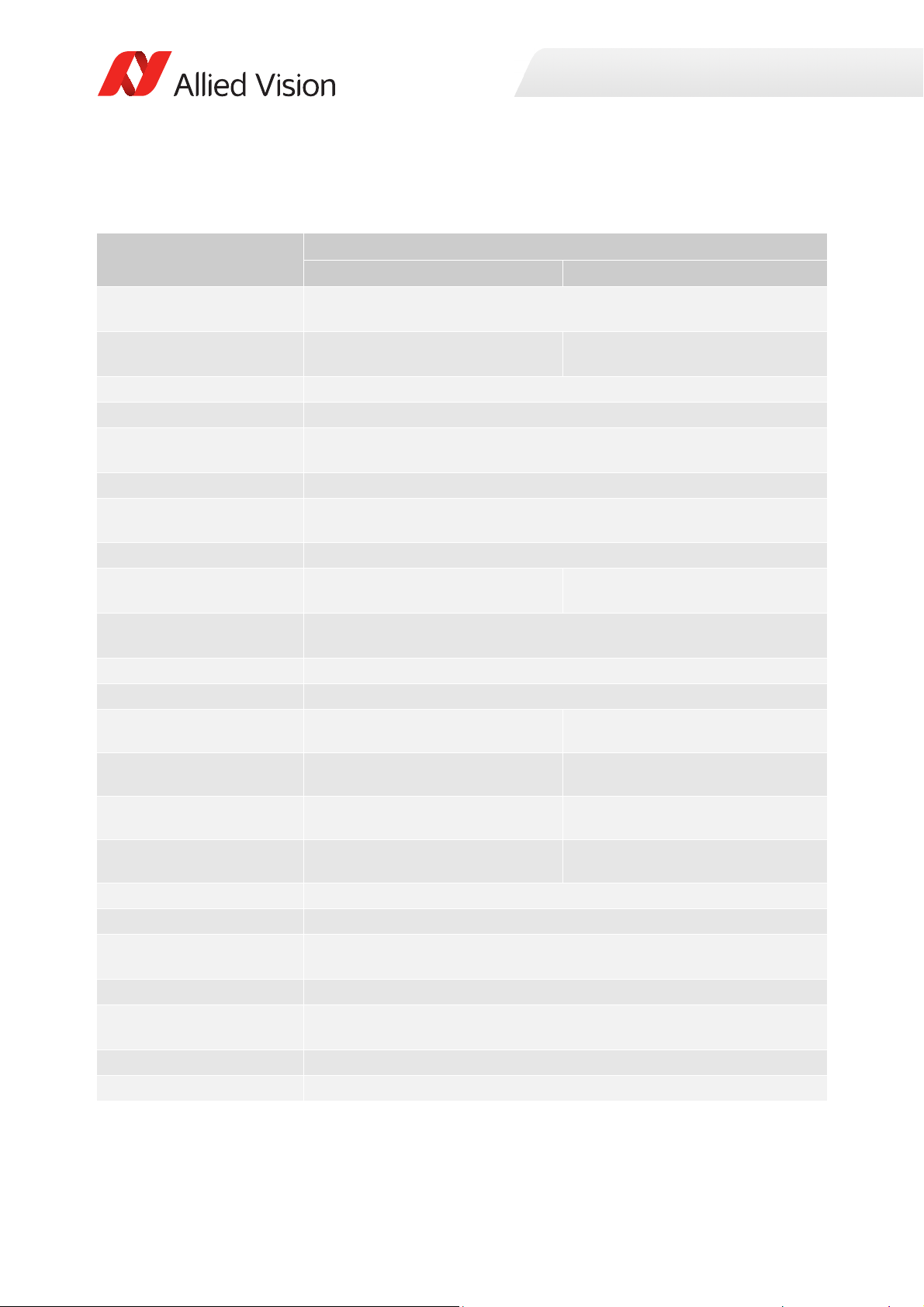
Prosilica GT1920, GT1920C
Specification
Feature
Resolution 1936 (H) × 1456 (V)
Sensor Sony ICX674ALG with EXview
HAD II™ microlens technology
Sensor type Interline CCD, Progressive Scan
Shutter type Global
Sensor size Type 2/3
Pixel size 4.54 μm × 4.54 μm
Lens mount
Housing Extended format
Optical filter Standard: No optical filter
Optional: See the Modular Concept
Maximum frame rate at full
resolution
Maximum image bit depth
Image buffer
Monochrome formats
Color formats (YUV)
Color formats (RGB)
RAW formats
Exposure time control
Gain control
Binning Horizontal: 1 to 8 columns
Decimation X/Y Horizontal and vertical: 1, 2, 4, 8 factor
Sensor taps Four-tap
TTL (non-isolated) I/Os
Opto-isolated I/Os
Mono8, Mono12, Mono12Packed,
Mono14
N/A YUV411Packed, YUV422Packed,
N/A RGB8Packed, BGR8Packed,
N/A BayerGR8, BayerGR12,
Prosilica GT1920 Prosilica GT1920
2.8 MP
Sony ICX674AQG with EXview
HAD II™ microlens technology
10.972 mm diagonal
Standard: C-Mount
Optional: See the
Four-tap mode: 40.7 fps
One-tap mode: 11.6 fps
14-bit (monochrome), 12-bit (color)
10 µs to 26.8 s, 1 µs increments
0 to 33 dB; 1 dB increments
Vertical: 1 to 8 rows
Single-tap switchable in Vimba Viewer 2.0 or later
1 input, 2 outputs
1 input, 2 outputs
Modular Concept
Standard: IRC30 IR cut filter
Optional: See the Modular Concept
128 MB
Mono8
YUV444Packed
RGBA8Packed, BGRA8Packed
BayerRG12Packed
Specifications
Table 19: Prosilica GT1920, GT1920C model specifications
50Prosilica GT Technical Manual V2.9.0
Page 51
Specification
Specifications
Feature
RS232
Voltage requirements
Power consumption
Trigger latency
Prosilica GT1920 Prosilica GT1920
1 TxD, 1 RxD
7 to 25 VDC; PoE
4.9 W @ 12 VDC; 6.0 W PoE
2 µs
Trigger jitter ±20 ns
Propagation delay (tpd)
Operating temperature
Storage temperature
Operating humidity
Body dimensions (L × W × H)
Mass (typical)
Interface
Interface standard
30 ns for non-isolated I/O; 70 ns for isolated I/O
-20 °C to +60 °C ambient temperature (without condensation)
-20 °C to +70 °C ambient temperature (without condensation)
20 to 80% non-condensing
92 × 53.3 × 33 mm
224 g
IEEE 802.3 1000BASE-T (Gigabit Ethernet), IEEE 802.3af (PoE)
GigE Vision® Standard V1.2
Camera control standard GenICam SFNC V1.2.1
Regulations
CE, RoHS, REACH, WEEE, FCC, ICES
Temperature monitoring Available for main board and sensor board.
Resolution: 0.031; Accuracy: ±1 °C
Table 19: Prosilica GT1920, GT1920C model specifications (continued)
51Prosilica GT Technical Manual V2.9.0
Page 52
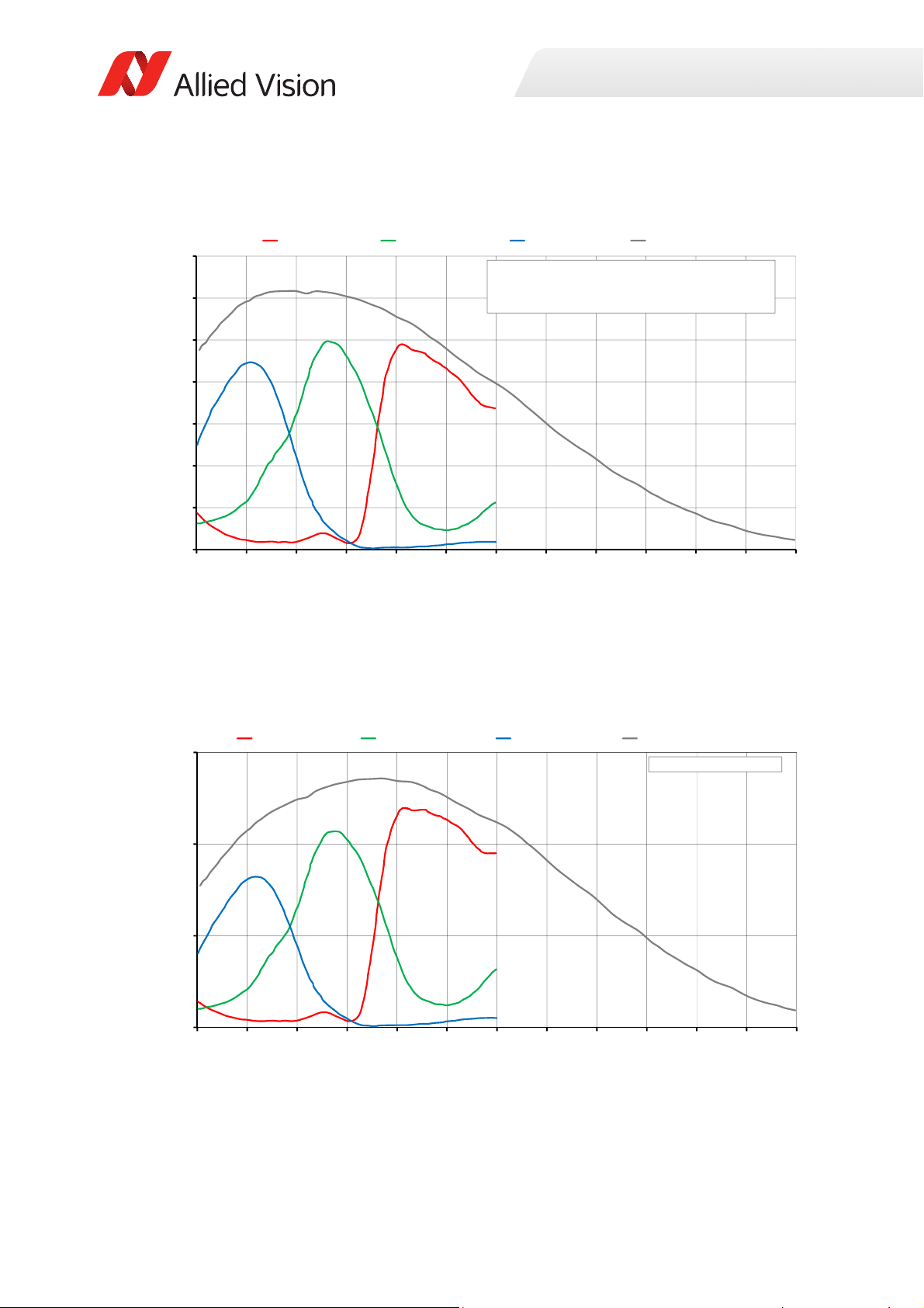
Absolute QE
0%
10%
20%
30%
40%
50%
60%
70%
400 450 500 550 600 650 700 750 800 850 900 950 1000
QuantumEfficiency[%]
Wavel ength[nm]
SonyICX674absoluteQE
AllmeasurementsweredonewithoutprotectionglassorIRcutfilter.
Withprotectionglassorfilters,quantumefficiency(QE)decreasesbyapproximately10%.
TheuncertaintyinmeasurementoftheQEis+/Ͳ 10.25%.
Thevaluesaretypicalandaresubjecttominorvariations.
RedQE GreenQE BlueQE MonochromeQE
0.0000
0.1000
0.2000
0.3000
400 450 500 550 600 650 700 750 800 850 900 950 1000
SpectralResponse[A/W]
Wavelength[nm]
SonyICX674spectralresponse
RedResponse GreenResponse BlueResponse MonochromeResponse
Specifications
Figure 14: Prosilica GT1920, GT1920C (Sony ICX674) absolute QE
Spectral response
Figure 15: Prosilica GT1920, GT1920C (Sony ICX674) spectral response
52Prosilica GT Technical Manual V2.9.0
Page 53
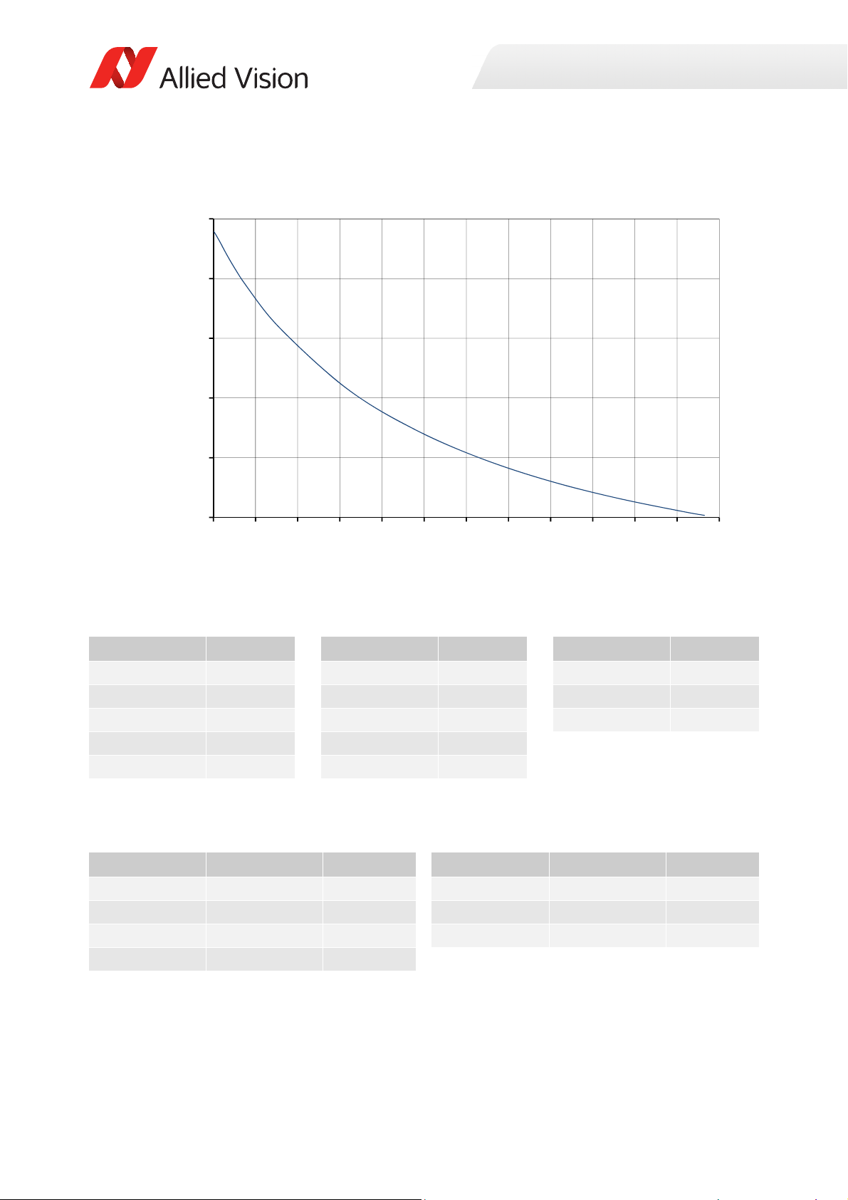
ROI frame rate
40
60
80
100
120
140
0 125 250 375 500 625 750 875 1000 1125 1250 1375 1500
Framerate[fps]
ROIheight[pixels]
Specifications
Figure 16: Frame rate as function of ROI height [width=1936 pixels]
Height in pixels Frame rate Height in pixels Frame rate Height in pixels Frame rate
1456 40.7 600 69.3 20 132.2
1400 41.8 400 82.8 10 134.2
1200 46.4 200 103.1 2 135.7
1000 52.1 100 117.2
800 59.5 50 126
Table 20: Frame rate as a function of ROI height [width=1936 pixels]
The following table shows how binning affects frame rate.
BinningVertical Height in pixels Frame rate BinningVertical Height in pixels Frame rate
2 728 70.3 6 242 135.1
3 484 92.8 7 208 144.1
4 364 110.0 8 182 151.7
5 290 124.1
Table 21: Frame rate as a function of ROI height with vertical binning enabled
53Prosilica GT Technical Manual V2.9.0
Page 54
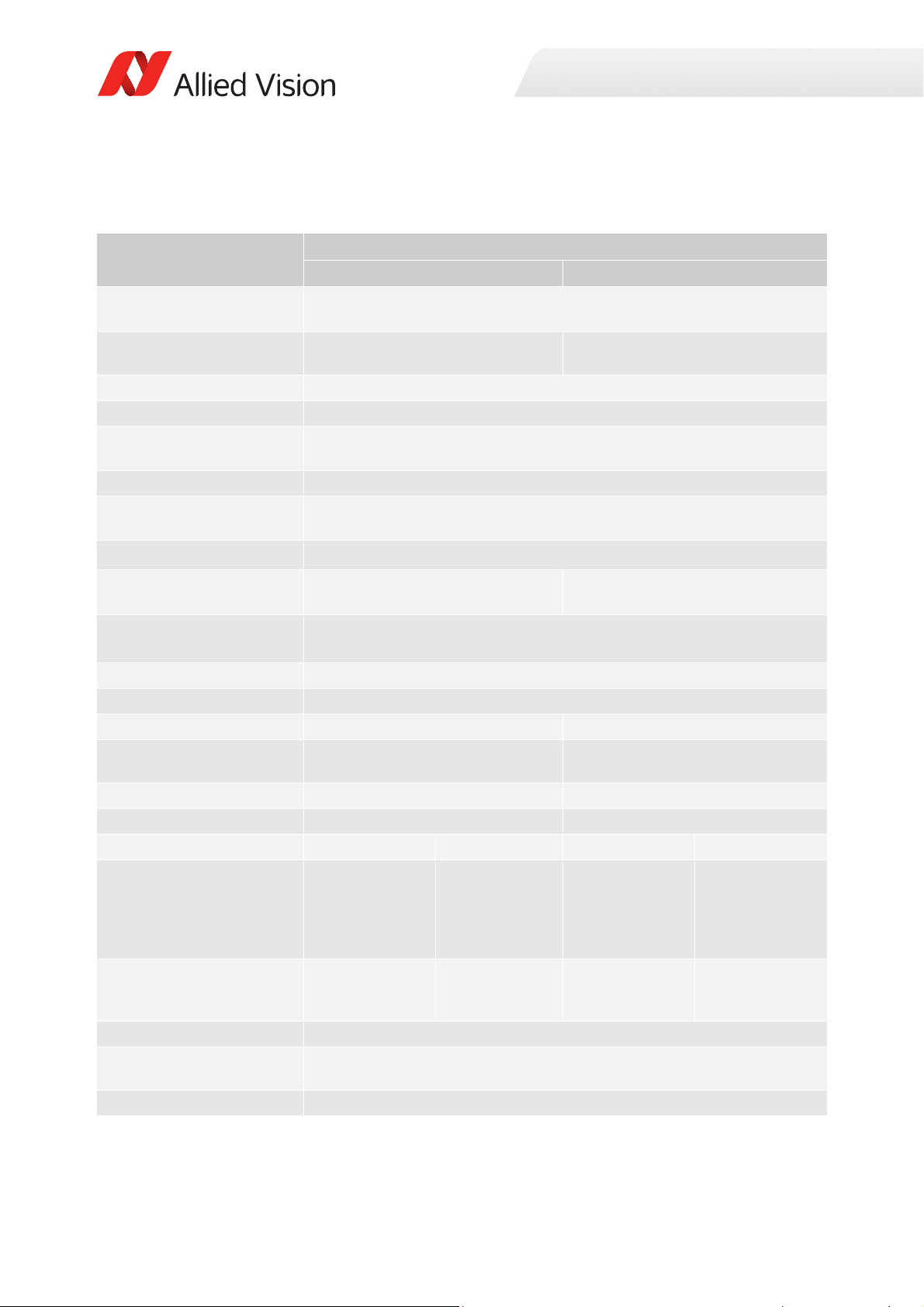
Prosilica GT1930, GT1930C
Specification
Feature
Resolution 1936 (H) × 1216 (V)
Sensor
Sony IMX174LLJ Exmor with Pregius®
global shutter
Sensor type
Shutter type Global
Sensor size
Pixel size 5.86 μm × 5.86 μm
Lens mount
Housing
1
Optical filter Standard: No optical filter
Optional: See the Modular Concept
Maximum frame rate at full
resolution
Maximum image bit depth
Image buffer
Monochrome formats
Color formats (YUV)
Color formats (RGB)
RAW formats
Mono8, Mono12, Mono12Packed Mono8
N/A YUV411Packed, YUV422Packed,
N/A RGB8Packed, BGR8Packed
N/A BayerRG8, BayerRG12
Exposure time control Pixel format Range Pixel format Range
Mono8, Mono12,
Mono12Packed
Gain control
Binning
Decimation X/Y Horizontal and vertical: 1, 2, 4, 8 factor
Prosilica GT1930 Prosilica GT1930C
2.4 MP
Sony IMX174LQJ Exmor with Pregius®
global shutter
CMOS
Type 1/1.2
13.4 mm diagonal
Standard: C-Mount
Optional: See the
Modular Concept
Standard format
Standard: IRC30 IR cut filter
Optional: See the Modular Concept
50.7 fps
55.8 fps burst mode
12-bit
128 MB
YUV444Packed
42 μs to 88 s Mono8,
BayerRG8,
BayerRG12,
YUV411Packed,
YUV422Packed
RGB8Packed,
BGR8Packed,
YUV444Packed
0.0 to 40.0 dB, 0.1 dB increments
Horizontal: 1 to 4 pixels
Vertical: 1 to 4 rows
2
28 μs to 88 s
14 μs increments
56 μs to 88 s
28 μs increments
Specifications
Table 22: Prosilica GT1930, GT1930C model specifications
54Prosilica GT Technical Manual V2.9.0
Page 55
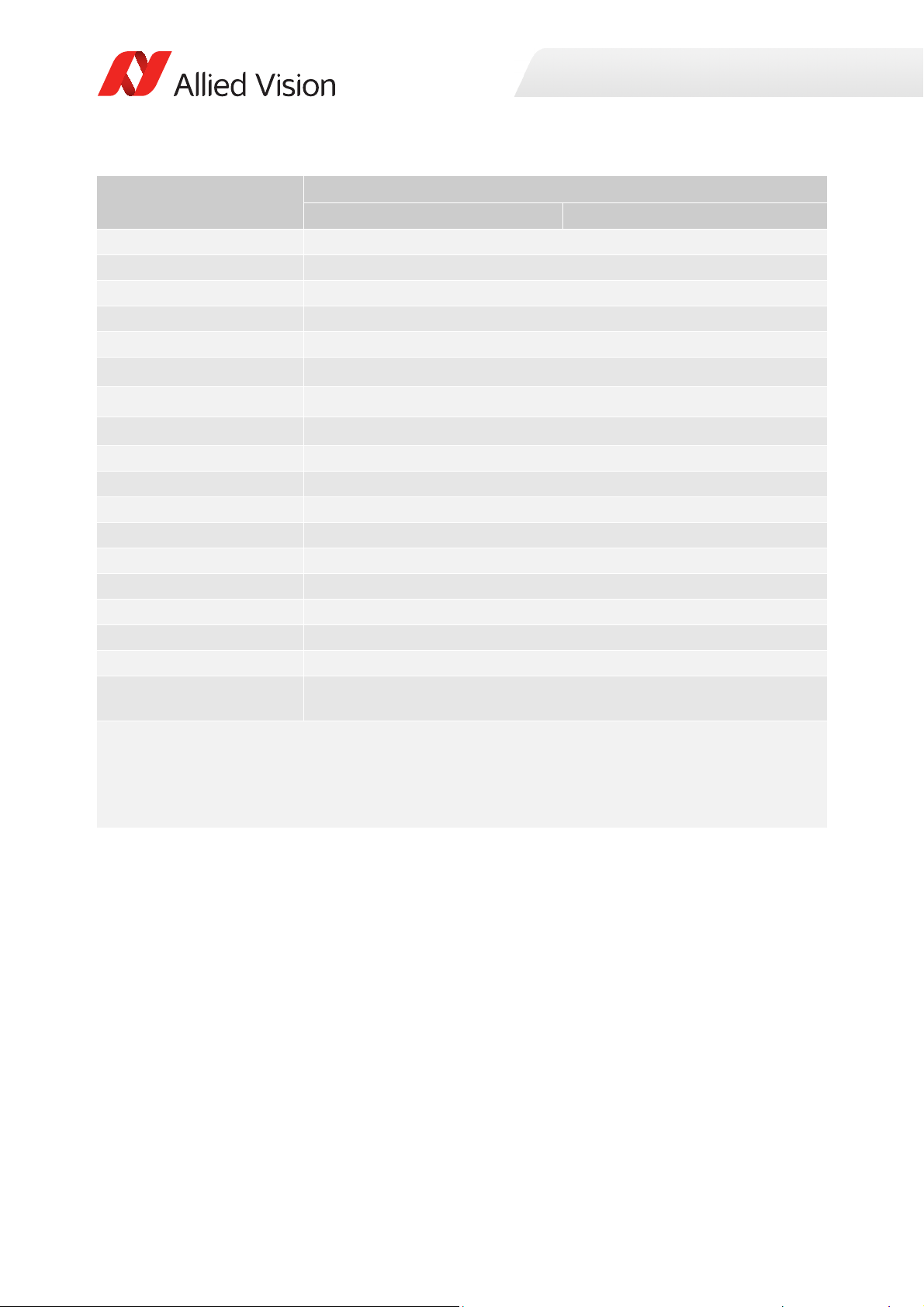
Specification
Specifications
Feature
TTL (non-isolated) I/Os
Prosilica GT1930 Prosilica GT1930C
1 input, 2 outputs
Opto-isolated I/Os 1 input, 2 outputs
RS232 1 TxD, 1 RxD
Voltage requirements 7 to 25 VDC; PoE
Power consumption 3.4 W @ 12 VDC; 4.2 W PoE
Trigger latency
Trigger jitter
3
3
50.1 µs
±7.2 µs
Propagation delay (tpd) 30 ns for non-isolated I/O; 70 ns for isolated I/O
Operating temperature -20 °C to +65 °C ambient temperature (without condensation)
Storage temperature -20 °C to +70 °C ambient temperature (without condensation)
Operating humidity 20 to 80% non-condensing
Body dimensions (L × W × H) 86 × 53 × 33 mm
Mass (typical) 211 g
Interface IEEE 802.3 1000BASE-T (Gigabit Ethernet), IEEE 802.3af (PoE)
Interface standard GigE Vision® Standard V1.2
Camera control standard GenICam SFNC V1.2.1
Regulations CE, RoHS, REACH, WEEE, FCC, ICES
Temperature monitoring Available for main board only.
Resolution: 0.031; Accuracy: ±1 °C
1
The Prosilica GT1930, GT1930C housing lens protrusion is 2.3 mm shorter than a regular standard housing.
2
These values are calculated directly from the microcontroller source. These values are only valid for pixel formats ≤16 bit
per pixel.
3
GigE host controller card with jumbo packets is required. See Hardware Selection for Allied Vision GigE Cameras
application note for a list of recommended GigE host controller cards.
Table 22: Prosilica GT1930, GT1930C model specifications (continued)
55Prosilica GT Technical Manual V2.9.0
Page 56
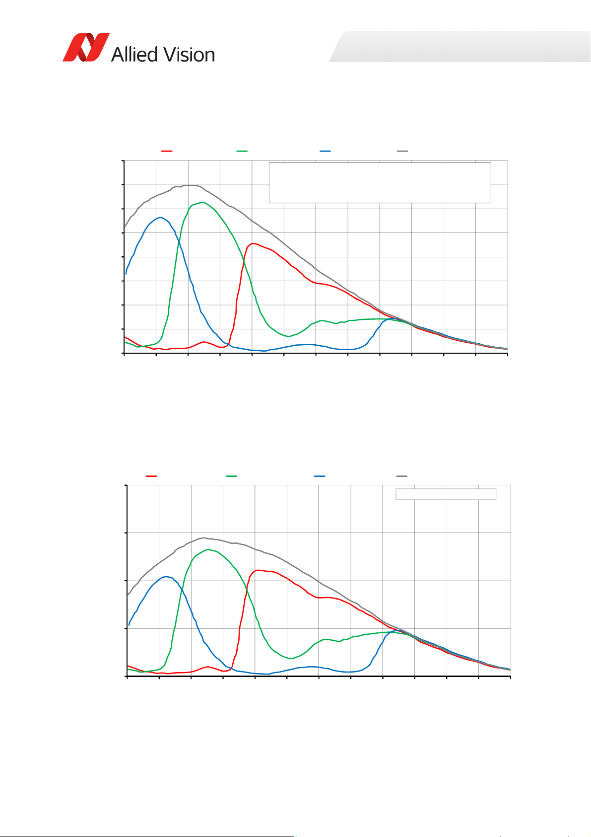
Absolute QE
0%
10%
20%
30%
40%
50%
60%
70%
80%
400 450 500 550 600 650 700 750 800 850 900 950 1000
QuantumEfficiency[%]
Wavelength[nm]
SonyIMX174absoluteQE
AllmeasurementsweredonewithoutprotectionglassorIRcutfilter.
Withprotectionglassorfilters,quantumefficiency(QE)decreasesbyapproximately10%.
TheuncertaintyinmeasurementoftheQEis+/Ͳ 10.25%.
Thevaluesaretypicalandaresubjecttominorvariations.
RedQE GreenQE BlueQE MonochromeQE
0.0000
0.1000
0.2000
0.3000
0.4000
400 450 500 550 600 650 700 750 800 850 900 950 1000
SpectralResponse[A/W]
Wavelength[nm]
SonyIMX174spectralresponse
RedResponse GreenResponse BlueResponse MonochromeResponse
Specifications
Figure 17: Prosilica GT1930, GT1930C (Sony IMX174) absolute QE
Spectral response
Figure 18: Prosilica GT1930, GT1930C (Sony IMX174) spectral response
56Prosilica GT Technical Manual V2.9.0
Page 57
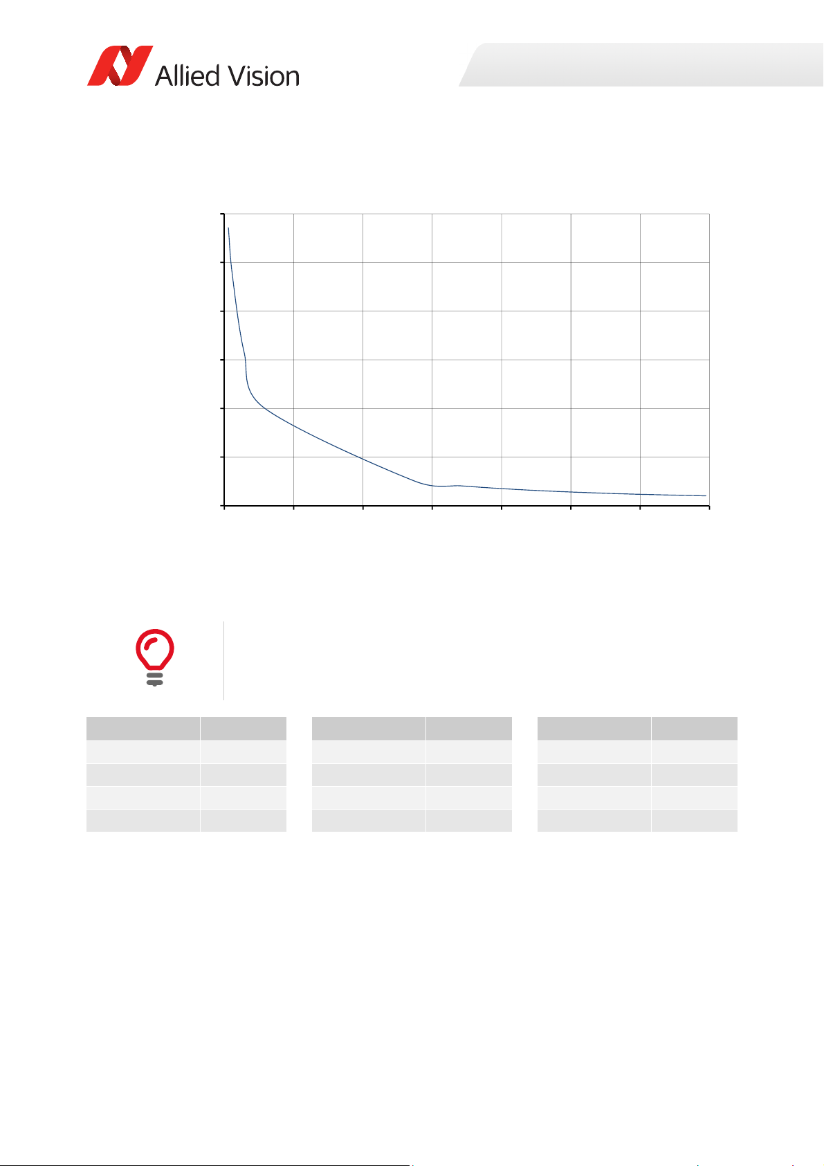
ROI frame rate
0
250
500
750
1000
1250
1500
0 175 350 525 700 875 1050 1225
Framerate[fps]
ROIheight[pixels]
Specifications
Figure 19: Frame rate as a function of ROI height [width=1936 pixels]
There will be an increase in frame rate with reduced width if the camera is
bandwidth limited.
Height in pixels Frame rate Height in pixels Frame rate Height in pixels Frame rate
1216 50.7 960 64 100 503.6
1200 51.4 768 80.1 50 787
1080 57 600 102 20 1187.2
1024 60 480 126.9 10 1429.4
Table 23: Frame rate as a function of ROI height [width=1936 pixels]
57Prosilica GT Technical Manual V2.9.0
Page 58
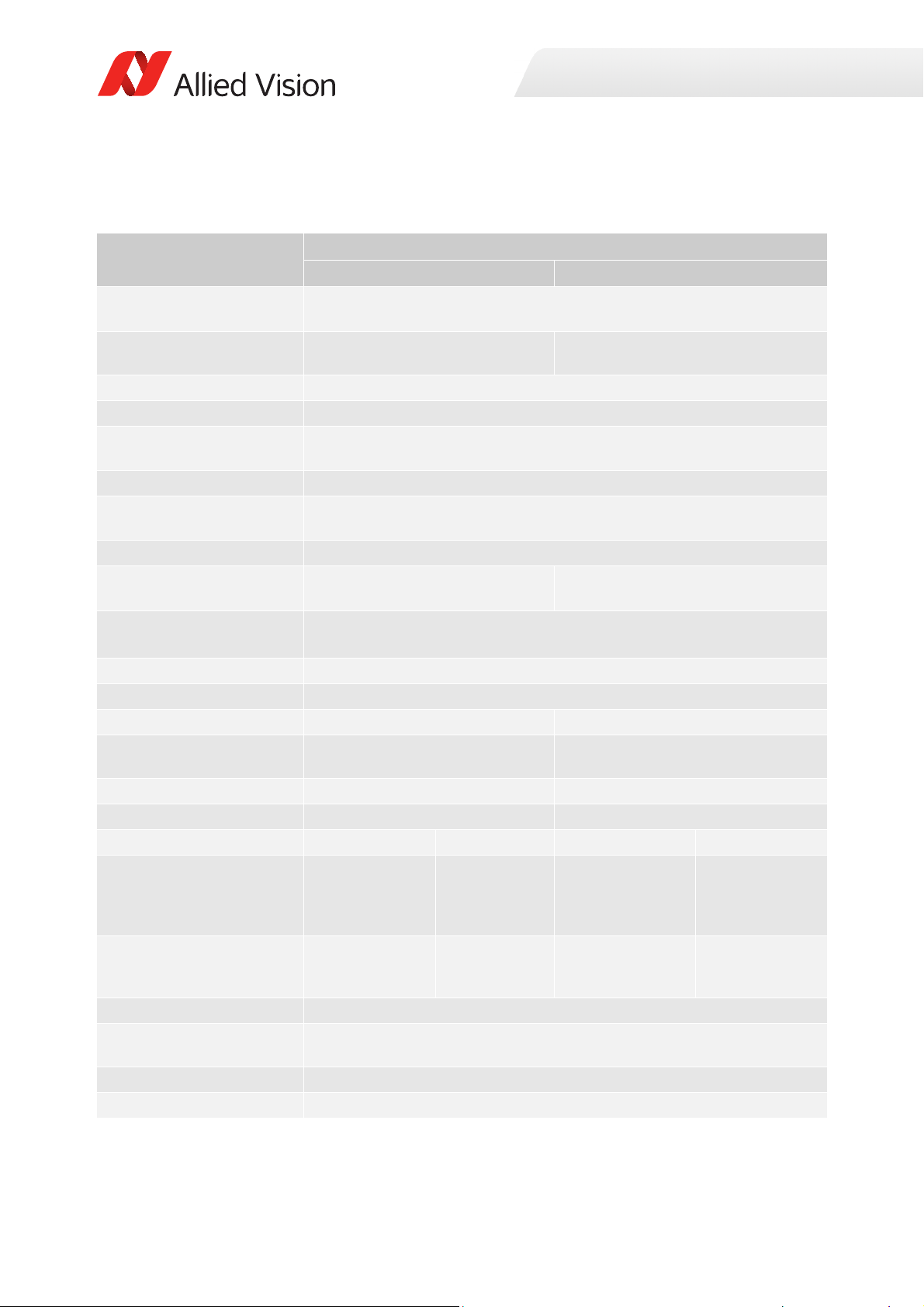
Prosilica GT1930L, GT1930LC
Specification
Feature
Resolution 1936 (H) × 1216 (V)
Sensor
Sony IMX174LLJ Exmor with Pregius®
global shutter
Sensor type
Shutter type Global
Sensor size
Pixel size 5.86 μm × 5.86 μm
Lens mount
1
Housing Large format
Optical filter Standard: No optical filter
Optional: See the Modular Concept
Maximum frame rate at full
resolution
Maximum image bit depth
Image buffer
Monochrome formats
Color formats (YUV)
Color formats (RGB)
RAW formats
Mono8, Mono12, Mono12Packed Mono8
N/A YUV411Packed, YUV422Packed,
N/A RGB8Packed, BGR8Packed
N/A BayerRG8, BayerRG12
Exposure time control Pixel format Range Pixel format Range
Mono8, Mono12,
Mono12Packed
Gain control
Binning
Decimation X/Y Horizontal and vertical: 1, 2, 4, 8 factor
TTL (non-isolated) I/Os
Prosilica GT1930L Prosilica GT1930LC
2.4 MP
Sony IMX174LQJ Exmor with Pregius®
global shutter
CMOS
Type 1/1.2
13.4 mm
Standard: EF-Mount PA
Optional: See the
diagonal
Modular Concept
Standard: IRC30 IR cut filter
Optional: See the Modular Concept
50.7 fps
55.8 fps burst mode
12-bit
128 MB
YUV444Packed
42 μs to 88 s Mono8, BayerRG8,
BayerRG12,
YUV411Packed,
YUV422Packed
RGB8Packed,
BGR8Packed,
YUV444Packed
0.0 to 40.0 dB, 0.1 dB increments
Horizontal: 1 to 4 pixels
Vertical: 1 to 4 rows
1 input, 2 outputs
2
28 μs to 88 s
14 μs increments
56 μs to 88 s
28 μs increments
Specifications
Table 24: Prosilica GT1930L, GT1930LC model specifications
58Prosilica GT Technical Manual V2.9.0
Page 59

Specification
Specifications
Feature
Opto-isolated I/Os
Prosilica GT1930L Prosilica GT1930LC
1 input, 2 outputs
RS232 1 TxD, 1 RxD
Voltage requirements 7 to 25 VDC; PoE
Power consumption 3.24 W @ 12 VDC; 3.88 W PoE
Trigger latency
Trigger jitter
3
3
50.1 µs
±7.2 µs
Propagation delay (tpd) 30 ns for non-isolated I/O; 70 ns for isolated I/O
Operating temperature
4
-30 to +75 °C DeviceTemperatureSelector = Sensor,
-30 to +80 °C
DeviceTemperatureSelector = Main,
-30 to +70 °C housing temperature (without condensation),
-30 to +65 °C ambient temperature (without condensation)
Storage temperature -40 °C to +80 °C ambient temperature (without condensation)
Operating humidity 20 to 80% non-condensing
Body dimensions (L × W × H) 96 × 66 × 53.3 mm
Mass (typical) 372 g
Interface IEEE 802.3 1000BASE-T (Gigabit Ethernet), IEEE 802.3af (PoE)
Interface standard GigE Vision® Standard V1.2
Camera control standard GenICam SFNC V1.2.1
Regulations CE, RoHS, REACH, WEEE, FCC, ICES
Temperature monitoring Available for main board only.
Resolution: 0.031; Accuracy: ±1 °C
1
To enable EF lens control on Prosilica GT cameras you must update firmware to version 01.54.14263 or later.
2
GigE host controller card with jumbo packets is required. See the Hardware Selection for Allied Vision GigE Cameras
application note for a list of recommended GigE host controller cards.
3
These values are calculated directly from the microcontroller source. These values are only valid for pixel formats ≤16 bit
per pixel.
4
Selects the site which temperature is reported. For more information on DeviceStatus, see the GigE Features
Reference.
Table 24: Prosilica GT1930L, GT1930LC model specifications (continued)
59Prosilica GT Technical Manual V2.9.0
Page 60
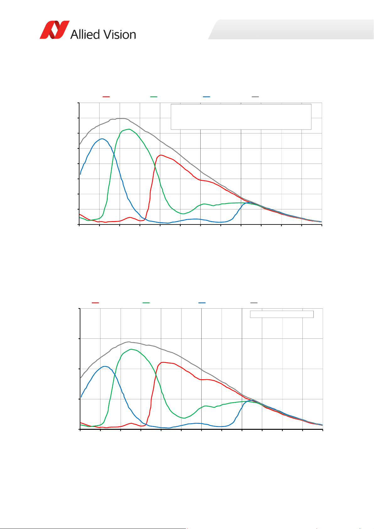
Absolute QE
0%
10%
20%
30%
40%
50%
60%
70%
80%
400 450 500 550 600 650 700 750 800 850 900 950 1000
QuantumEfficiency[%]
Wavelength[nm]
SonyIMX174absoluteQE
AllmeasurementsweredonewithoutprotectionglassorIRcutfilter.
Withprotectionglassorfilters,quantumefficiency(QE)decreasesbyapproximately10%.
TheuncertaintyinmeasurementoftheQEis+/Ͳ 10.25%.
Thevaluesaretypicalandaresubjecttominorvariations.
RedQE GreenQE BlueQE MonochromeQE
0.0000
0.1000
0.2000
0.3000
0.4000
400 450 500 550 600 650 700 750 800 850 900 950 1000
SpectralResponse[A/W]
Wavelength[nm]
SonyIMX174spectralresponse
RedResponse GreenResponse BlueResponse MonochromeResponse
Specifications
Figure 20: Prosilica GT1930L, GT1930LC (Sony IMX174) absolute QE
Spectral response
Figure 21: Prosilica GT1930L, GT1930LC (Sony IMX174) spectral response
60Prosilica GT Technical Manual V2.9.0
Page 61
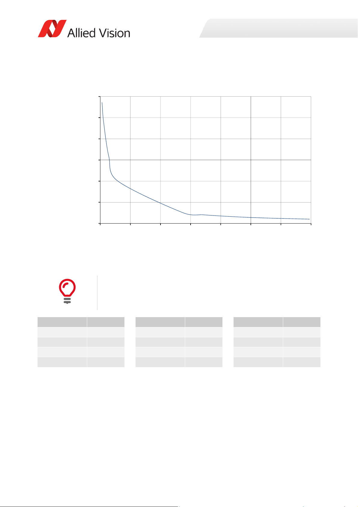
ROI frame rate
0
250
500
750
1000
1250
1500
0 175 350 525 700 875 1050 1225
Framerate[fps]
ROIheight[pixels]
Specifications
Figure 22: Frame rate as a function of ROI height [width=1936 pixels]
There will be an increase in frame rate with reduced width if the camera is
bandwidth limited.
Height in pixels Frame rate Height in pixels Frame rate Height in pixels Frame rate
1216 50.7 960 64 100 503.6
1200 51.4 768 80.1 50 787
1080 57 600 102 20 1187.2
1024 60 480 126.9 10 1429.4
Table 25: Frame rate as a function of ROI height [width=1936 pixels]
61Prosilica GT Technical Manual V2.9.0
Page 62
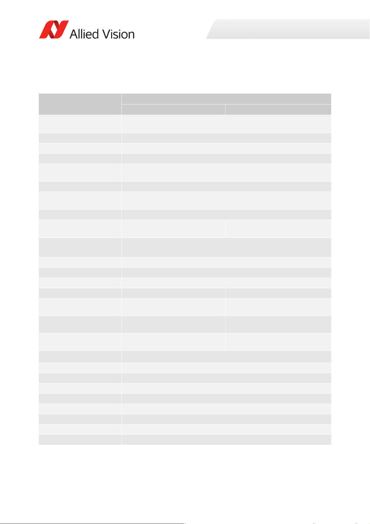
Prosilica GT2000, GT2000NIR, GT2000C
Specification
Feature
Resolution 2048 (H) × 1088 (V)
Sensor CMOSIS/ams CMV2000
Sensor type CMOS
Shutter type Global
Sensor size
Pixel size 5.5 μm × 5.5 μm
Lens mount
1
Housing Standard format
Optical filter Standard: No optical filter
Maximum frame rate at full
resolution
Maximum image bit depth
Image buffer
StreamHoldCapacity
Monochrome formats Mono8, Mono12, Mono12Packed Mono8
Color formats (YUV) N/A
Color formats (RGB) N/A
RAW formats N/A
Exposure time control
3
Gain control
Binning
Decimation X/Y Horizontal and vertical: 1, 2, 4, 8 factor
TTL (non-isolated) I/Os
Opto-isolated I/Os
RS232
Voltage requirements
Power consumption
Prosilica GT2000, GT2000NIR Prosilica GT2000C
2.2 MP
Typ e 2/3
12.7 mm
Standard: C-Mount
Optional: See the
diagonal
Modular Concept
Standard: IRC30 IR cut filter
Optional: See the Modular Concept
Optional: See the Modular Concept
53.7 fps
60.1 fps burst mode
12-bit
128 MB
Up to 29 frames at full resolution
YUV411Packed, YUV422Packed,
YUV444Packed
RGB8Packed, BGR8Packed,
RGBA8Packed, BGRA8Packed
BayerGB8, BayerGB12,
BayerGB12Packed
25 µs to 122 s, 1 µs increments
0 to 26 dB; 1 dB increments
N/A
1 input, 2 outputs
1 input, 2 outputs
1 TxD, 1 RxD
7 to 25 VDC; PoE
3.4 W @ 12 VDC; 4.2 W PoE
2
Specifications
Table 26: Prosilica GT2000, GT2000NIR, GT2000C model specifications
62Prosilica GT Technical Manual V2.9.0
Page 63

Specification
Specifications
Feature
Prosilica GT2000, GT2000NIR Prosilica GT2000C
Trigger latency 700 ns
Trigger jitter ±20 ns
Propagation delay (tpd) 30 ns for non-isolated I/O; 70 ns for isolated I/O
Operating temperature -20 °C to +65 °C ambient temperature (without condensation)
Storage temperature -20 °C to +70 °C ambient temperature (without condensation)
Operating humidity 20 to 80% non-condensing
Body dimensions (L × W × H) 86 × 53.3 × 33 mm
Mass (typical) 210 g
Interface IEEE 802.3 1000BASE-T (Gigabit Ethernet), IEEE 802.3af (PoE)
Interface standard GigE Vision® Standard V1.2
Camera control standard GenICam SFNC V1.2.1
Regulations CE, RoHS, REACH, WEEE, FCC, ICES
Temperature monitoring Available for main board only.
Resolution: 0.031; Accuracy: ±1 °C
1
1 inch format lens recommended
2
GigE host controller card with jumbo packets is required. See the Hardware Selection for Allied Vision GigE Cameras
application note for a list of recommended GigE host controller cards.
3
Camera firmware version 01.52.8151 shows minimum exposure values without frame overhead time, i.e., 1 µs. See
sensor data sheet for details on frame overhead time.
Table 26: Prosilica GT2000, GT2000NIR, GT2000C model specifications (continued)
63Prosilica GT Technical Manual V2.9.0
Page 64
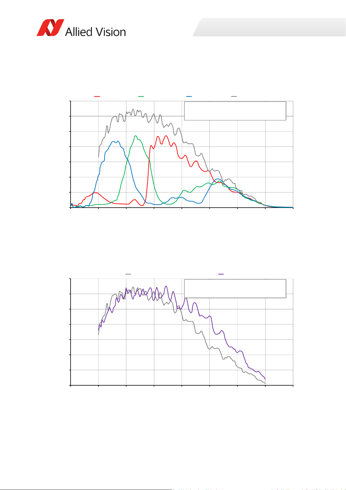
Absolute QE
0%
10%
20%
30%
40%
50%
60%
70%
300 400 500 600 700 800 900 1000 1100
QuantumEfficiency
Wavelength[nm]
CMOSIS/amsCMV2000absoluteQE
Allmeasurementsweredonewithoutprotectio nglassorIRcutfilter.
Withprotectionglassorf ilters,quantumefficiency(QE)decreasesbyapproximately10%.
Theuncertaintyinmeasurementofthe QEis+/Ͳ 10.25%.
Thevaluesaretypicalandaresubjecttominorvariations.
RedQE GreenQE BlueQE MonochromeQE
0%
10%
20%
30%
40%
50%
60%
70%
300 400 500 600 700 800 900 1000 1100
QuantumEfficiency
Wavelength[nm]
CMOSIS/amsCMV2000absoluteQE
Allmeasurementsweredonewithoutprotectio nglassorIRcutfilter.
Withprotectionglassorf ilters,quantumefficiency(QE)decreasesbyapproximately10%.
Theuncertaintyinmeasurementofthe QEis+/Ͳ 10.25%.
Thevaluesaretypicalandaresubjecttominorvariations.
MonochromeQE NIRQE
Specifications
Figure 23: Prosilica GT2000, GT2000C (CMOSIS/ams CMV2000) absolute QE
Figure 24: Prosilica GT2000, GT2000NIR (CMOSIS/ams CMV2000) absolute QE
64Prosilica GT Technical Manual V2.9.0
Page 65
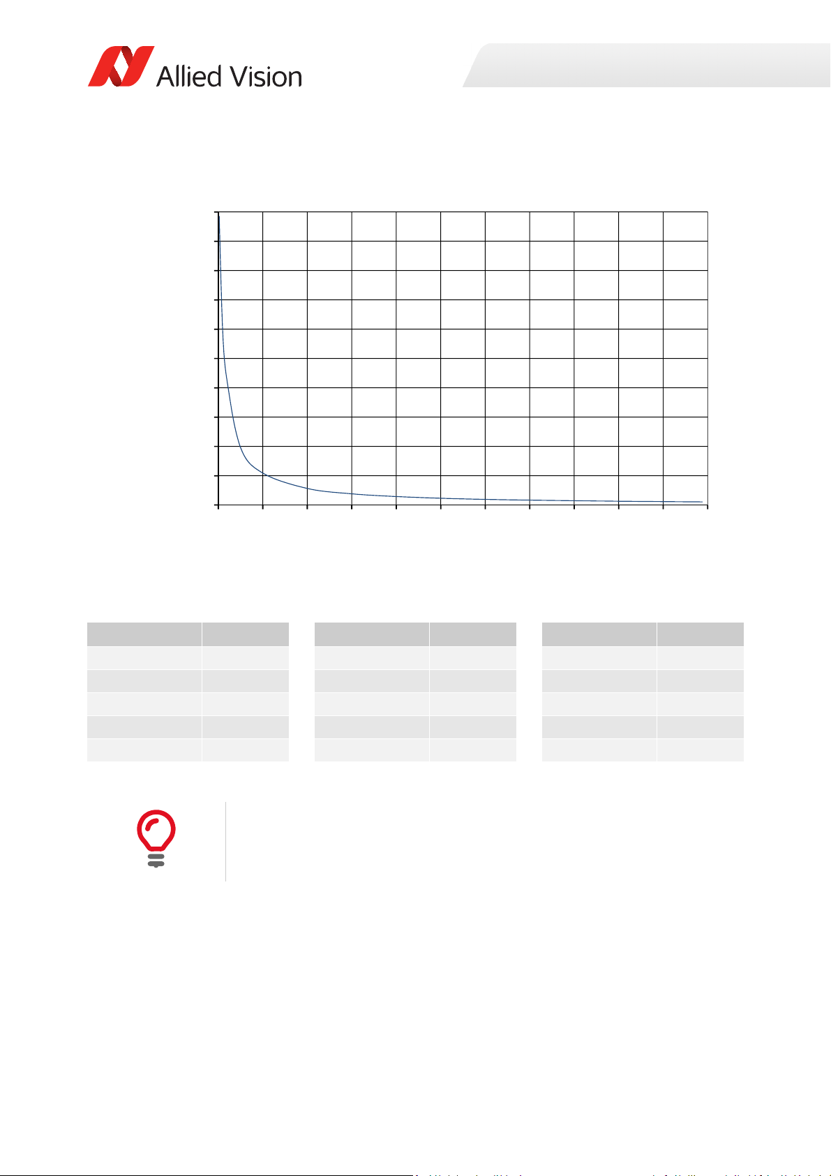
ROI frame rate
0
500
1000
1500
2000
2500
3000
3500
4000
4500
5000
0 100 200 300 400 500 600 700 800 900 1000 1100
Framerate[fps]
ROIheight[pixels]
Specifications
Figure 25: Frame rate as a function of ROI height [width=2048 pixels]
Height in pixels Frame rate Height in pixels Frame rate Height in pixels Frame rate
1088 53.7 600 96.8 100 545.3
1000 58.4 500 115.9 50 981.4
900 64.8 400 144.3 20 2105.3
800 72.9 300 191.2 10 2949.9
700 83.2 200 283.1 2 4926.1
Table 27: Frame rate as a function of ROI height [width=2048 pixels]
There will be an increase in frame rate with reduced width if the camera is
bandwidth limited.
65Prosilica GT Technical Manual V2.9.0
Page 66
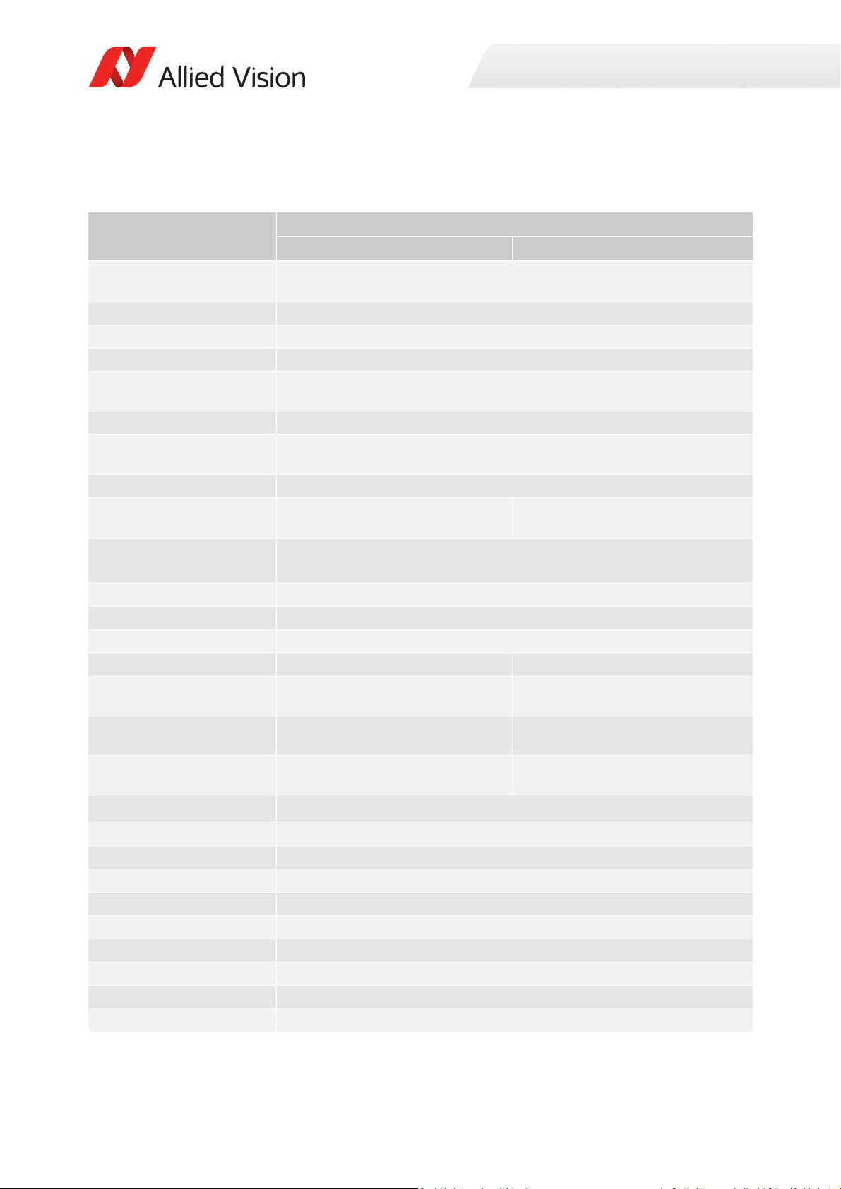
Prosilica GT2050, GT2050NIR, GT2050C
Specification
Feature
Resolution 2048 (H) × 2048 (V)
Sensor CMOSIS/ams CMV4000
Sensor type CMOS
Shutter type Global
Sensor size
Pixel size 5.5 μm × 5.5 μm
Lens mount
Housing Standard format
Optical filter Standard: No optical filter
Maximum frame rate at full
resolution
Maximum image bit depth
Image buffer
StreamHoldCapacity
Monochrome formats Mono8, Mono12, Mono12Packed Mono8
Color formats (YUV) N/A
Color formats (RGB) N/A
RAW formats N/A
Exposure time control
Gain control
Binning
Decimation X/Y Horizontal and vertical: 1, 2, 4, 8 factor
TTL (non-isolated) I/Os
Opto-isolated I/Os
RS232
Voltage requirements
Power consumption
Trigger latency
2
Prosilica GT2050, GT2050NIR Prosilica GT2050C
4.2 MP
Typ e 1
16.0 mm diagonal
Standard: C-Mount
Optional: See the
Optional: See the Modular Concept
32.0 burst mode
Up to 15 frames at full resolution
34 µs to 126.2 s, 1 µs increments
0 to 26 dB; 1 dB increments
1 input, 2 outputs
1 input, 2 outputs
7 to 25 VDC; PoE
3.5 W @ 12 VDC; 4.3 W PoE
Modular Concept
Standard: IRC30 IR cut filter
Optional: See the Modular Concept
28.6 fps
1
12-bit
128 MB
YUV411Packed, YUV422Packed,
YUV444Packed
RGB8Packed, BGR8Packed,
RGBA8Packed, BGRA8Packed
BayerGB8, BayerGB12,
BayerGB12Packed
N/A
1 TxD, 1 RxD
700 ns
Specifications
Table 28: Prosilica GT2050, GT2050NIR, GT2050C model specifications
66Prosilica GT Technical Manual V2.9.0
Page 67

Specification
Specifications
Feature
Prosilica GT2050, GT2050NIR Prosilica GT2050C
Trigger jitter ±20 ns
Propagation delay (tpd)
Operating temperature
Storage temperature
Operating humidity
Body dimensions (L × W × H)
Mass (typical)
Interface
Interface standard
30 ns for non-isolated I/O; 70 ns for isolated I/O
-20 °C to +65 °C ambient temperature (without condensation)
-20 °C to +70 °C ambient temperature (without condensation)
20 to 80% non-condensing
86 × 53.3 × 33 mm
210 g
IEEE 802.3 1000BASE-T (Gigabit Ethernet), IEEE 802.3af (PoE)
GigE Vision® Standard V1.2
Camera control standard GenICam SFNC V1.2.1
Regulations
CE, RoHS, REACH, WEEE, FCC, ICES
Temperature monitoring Available for main board only.
Resolution: 0.031; Accuracy: ±1 °C
1
GigE host controller card with jumbo packets is required. See the Hardware Selection for Allied Vision GigE Cameras
application note for a list of recommended GigE host controller cards.
2
Camera firmware version ≤ 01.52.8151 shows minimum exposure values without frame overhead time, i.e., 1 µs. See
sensor data sheet for details on frame overhead time.
Table 28: Prosilica GT2050, GT2050NIR, GT2050C model specifications (continued)
67Prosilica GT Technical Manual V2.9.0
Page 68
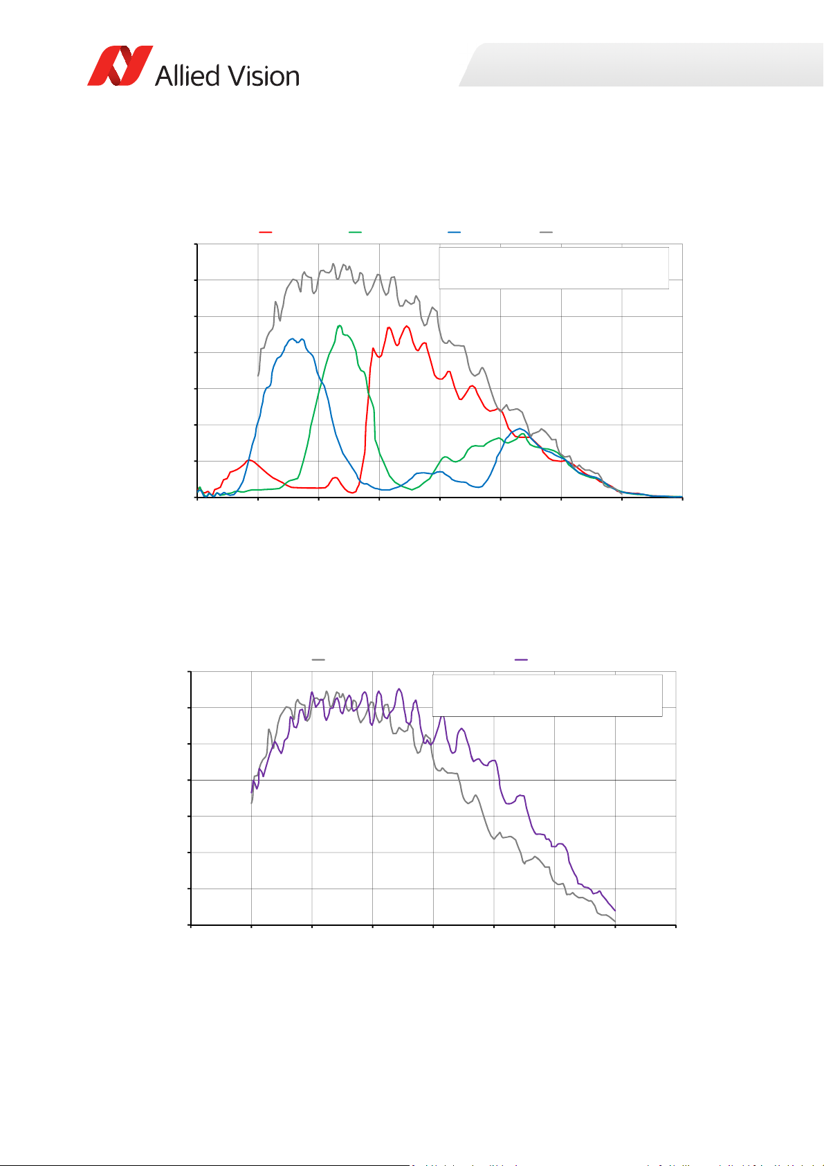
Absolute QE
0%
10%
20%
30%
40%
50%
60%
70%
300 400 500 600 700 800 900 1000 1100
QuantumEfficiency
Wavelen gth[nm]
CMOSIS/amsCMV4000absoluteQE
Allmeasurementsweredonewithoutprotectionglass orIRcutfilter.
Withprotectionglassorfilters,quantumefficiency(QE)decreases byapproximately10%.
Theuncertaintyinmeasurementofth eQEis+/Ͳ 10.25%.
Thevaluesaretypicalandaresubjecttominorvariations.
Red Green Blue MonochromeQE
0%
10%
20%
30%
40%
50%
60%
70%
300 400 500 600 700 800 900 1000 1100
QuantumEfficiency
Wavelen gth[nm]
CMOSIS/amsCMV4000absoluteQE
Allmeasurementsweredonewithoutprotectionglass orIRcutfilter.
Withprotectionglassorfilters,quantumefficiency(QE)decreases byapproximately10%.
Theuncertaintyinmeasurementofth eQEis+/Ͳ 10.25%.
Thevaluesaretypicalandaresubjecttominorvariations.
MonochromeQE NIRQE
Specifications
Figure 26: Prosilica GT2050, GT2050C (CMOSIS/ams CMV4000) absolute QE
Figure 27: Prosilica GT2050, GT2050NIR (CMOSIS/ams CMV4000) absolute QE
68Prosilica GT Technical Manual V2.9.0
Page 69
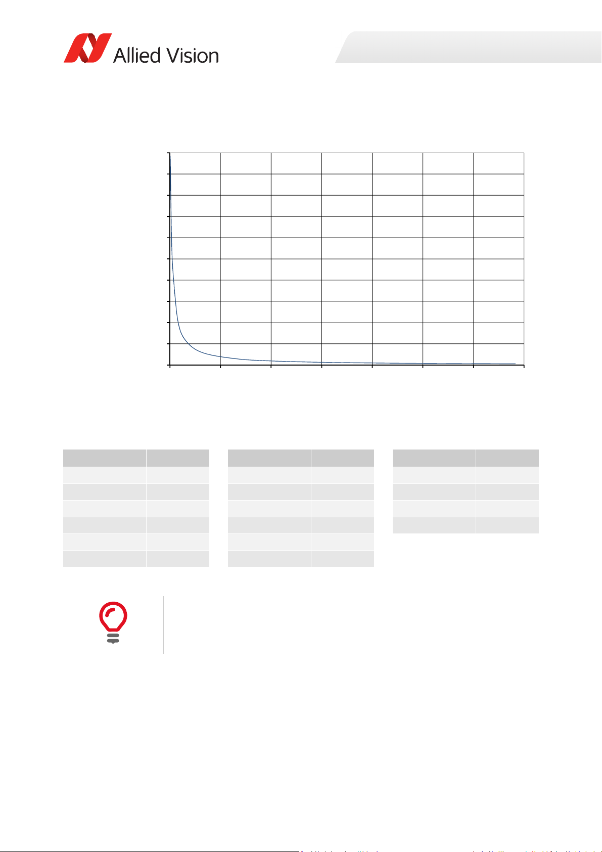
ROI frame rate
0
500
1000
1500
2000
2500
3000
3500
4000
4500
5000
0 300 600 900 1200 1500 1800 2100
Framerate[fps]
ROIheight[pixels]
Specifications
Figure 28: Frame rate as a function of ROI height [width=2048 pixels]
Height in pixels Frame rate Height in pixels Frame rate Height in pixels Frame rate
2048 28.6 1000 58.4 50 981.4
2000 29.3 800 72.9 20 2105.3
1800 32.6 600 96.8 10 2949.9
1600 36.6 400 144.3 2 4926.1
1400 41.8 200 283.1
1200 48.7 100 545.3
Table 29: Frame rate as a function of ROI height [width=2048 pixels]
There will be an increase in frame rate with reduced width if the camera is
bandwidth limited.
69Prosilica GT Technical Manual V2.9.0
Page 70
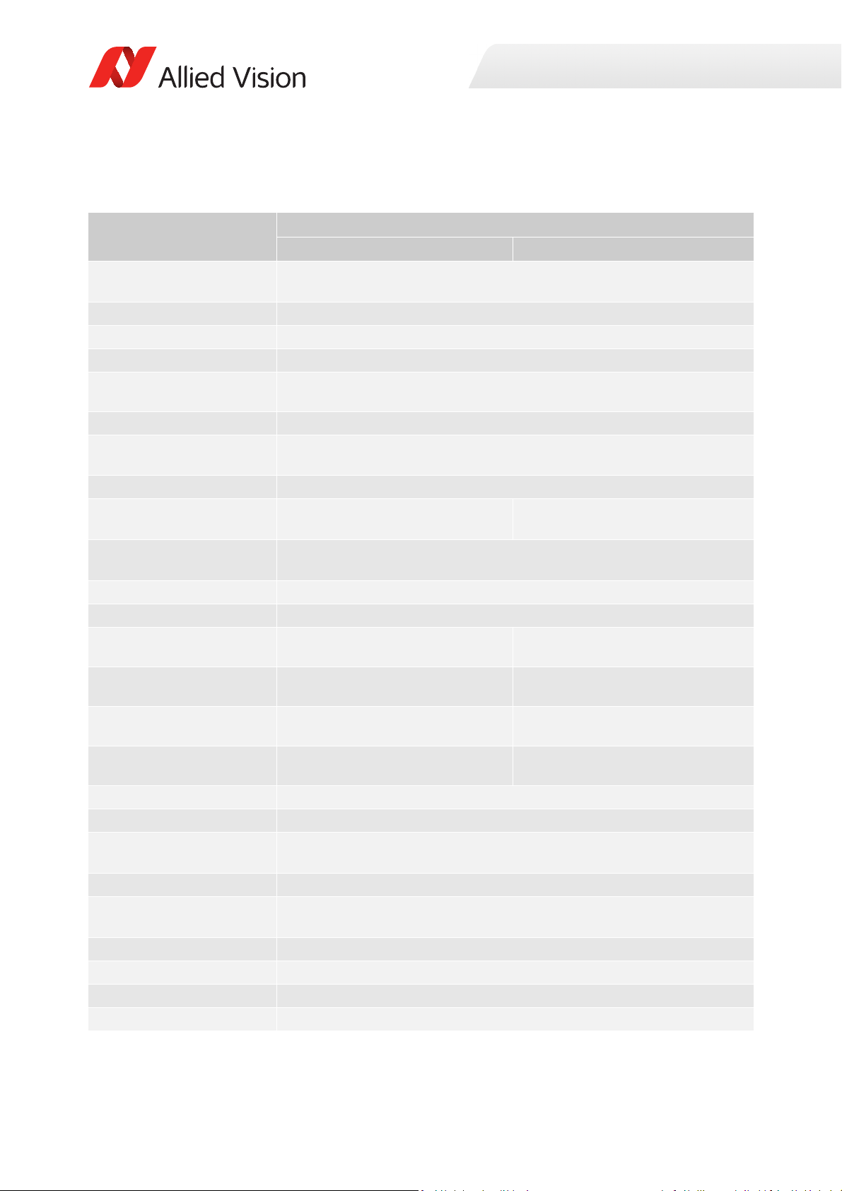
Prosilica GT2300, GT2300C
Specification
Feature
Resolution 2336 (H) × 1752 (V)
Sensor ON Semi KAI-04050 TRUESENSE Gen 2
Sensor type
Shutter type Global
Sensor size
Pixel size 5.5 μm × 5.5 μm
Lens mount
Housing Extended format
Optical filter Standard: No optical filter
Optional: See the Modular Concept
Maximum frame rate at full
resolution
Maximum image bit depth
Image buffer
Monochrome formats
Color formats (YUV)
Color formats (RGB)
RAW formats
Exposure time control
Gain control
Binning Horizontal: 1 to 8 columns
Decimation X/Y Horizontal and vertical: 1, 2, 4, 8 factor
Sensor taps Four-tap
TTL (non-isolated) I/Os
Opto-isolated I/Os
RS232
Voltage requirements
Mono8, Mono12, Mono12Packed,
Mono14
N/A YUV411Packed, YUV422Packed,
N/A RGB8Packed, BGR8Packed,
N/A BayerGR8, BayerGR12,
Prosilica GT2300 Prosilica GT2300C
4.1 MP
Interline CCD, Progressive Scan
Typ e 1
16.06 mm diagonal
Standard: C-Mount
Optional: See the
Four-tap mode: 29.3 fps
One-tap mode: 8.7 fps
14-bit (monochrome), 12-bit (color)
10 µs to 26.8 s, 1 µs increments
0 to 32 dB; 1 dB increments
Vertical: 1 to 8 rows
Single-tap switchable in Vimba Viewer 2.0 or later
1 input, 2 outputs
1 input, 2 outputs
7 to 25 VDC; PoE
Modular Concept
Standard: IRC30 IR cut filter
Optional: See the Modular Concept
128 MB
Mono8
YUV444Packed
RGBA8Packed, BGRA8Packed
BayerRG12Packed
1 TxD, 1 RxD
Specifications
Table 30: Prosilica GT2300, GT2300C model specifications
70Prosilica GT Technical Manual V2.9.0
Page 71
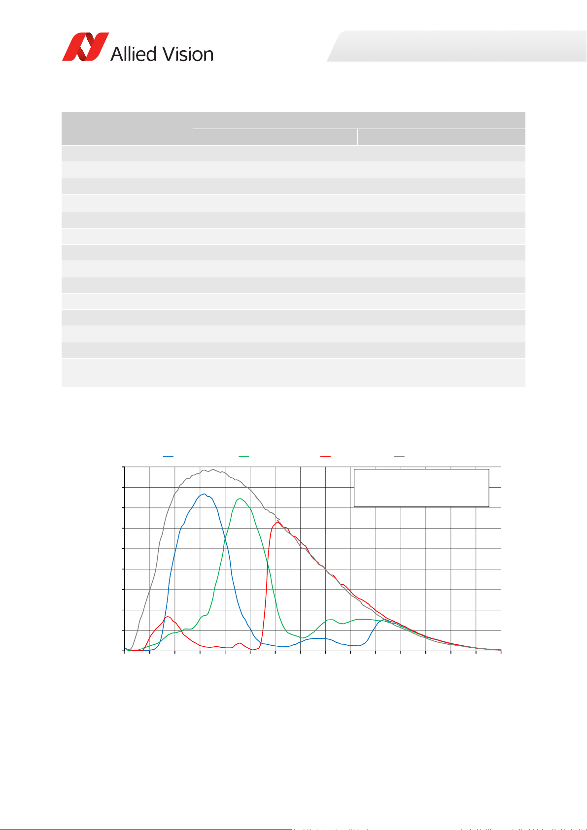
Specification
0%
5%
10%
15%
20%
25%
30%
35%
40%
45%
300 350 400 450 500 550 600 650 700 750 800 850 900 950 1000 1050
QuantumEfficiency
Wavelength[nm]
ONSemiconductorKAIͲ04050absoluteQE
ONSemiconductorGen2CFAmaterialforcolorsensors
Note:MeasuredwithARcoatedcoverglass.
TheuncertaintyofmeasurementoftheQEis+/Ͳ 10.25%.
Thevaluesaretypicalandaresubjecttominor variations.
BlueQE GreenQE RedQE MonochromeQE
Specifications
Feature
Power consumption
Trigger latency
Prosilica GT2300 Prosilica GT2300C
4.9 W @ 12 VDC; 6.0 W PoE
2.2 µs
Trigger jitter ±20 ns
Propagation delay (tpd)
Operating temperature
Storage temperature
Operating humidity
Body dimensions (L × W × H)
Mass (typical)
Interface
Interface standard
30 ns for non-isolated I/O; 70 ns for isolated I/O
-20 °C to +60 °C ambient temperature (without condensation)
-20 °C to +70 °C ambient temperature (without condensation)
20 to 80% non-condensing
92 × 53.3 × 33 mm
229 g
IEEE 802.3 1000BASE-T (Gigabit Ethernet), IEEE 802.3af (PoE)
GigE Vision® Standard V1.2
Camera control standard GenICam SFNC V1.2.1
Regulations
CE, RoHS, REACH, WEEE, FCC, ICES
Temperature monitoring Available for main board and sensor board.
Resolution: 0.031; Accuracy: ±1 °C
Table 30: Prosilica GT2300, GT2300C model specifications (continued)
Absolute QE
Figure 29: Prosilica GT2300, GT2300C (ON Semi KAI-04050 Gen 2) absolute QE
71Prosilica GT Technical Manual V2.9.0
Page 72
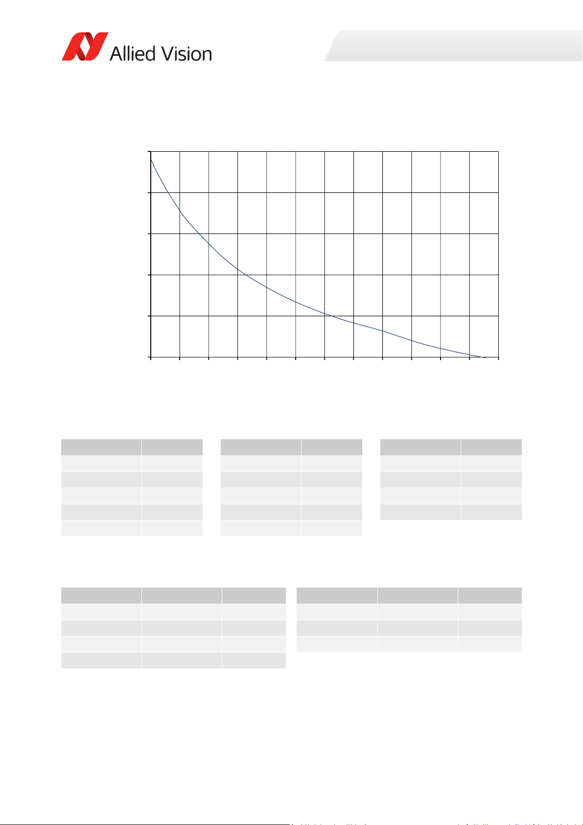
ROI frame rate
30
50
70
90
110
130
0 150 300 450 600 750 900 1050 1200 1350 1500 1650 1800
Framerate[fps]
ROIheight[pixels]
Specifications
Figure 30: Frame rate as a function of ROI height [width=2336 pixels]
Height in pixels Frame rate Height in pixels Frame rate Height in pixels Frame rate
1752 29.3 800 54.8 50 116.8
1600 32.1 600 63.9 20 122.2
1400 36.6 400 76.4 10 124.5
1200 42.7 200 95.2 2 125.9
1000 48 100 108.6
Table 31: Frame rate as a function of ROI height [width=2336 pixels]
The following table shows how binning affects frame rate.
BinningVertical Height in pixels Frame rate BinningVertical Height in pixels Frame rate
2 876 58.3 6 292 128.5
3 584 81.4 7 250 140.0
4 438 99.7 8 218 148.9
5 350 115.3
Table 32: Frame rate as a function of ROI height with vertical binning enabled
72Prosilica GT Technical Manual V2.9.0
Page 73
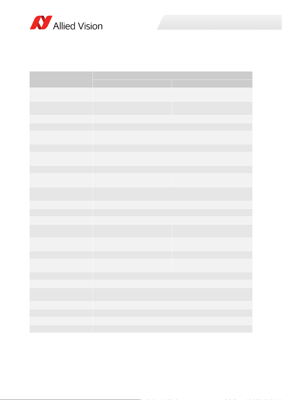
Prosilica GT2450, GT2450C
Specification
Feature
Resolution 2448 (H) × 2050 (V)
Sensor Sony ICX625ALA with Super HAD
CCD™ technology
Sensor type
Shutter type Global
Sensor size
Pixel size 3.45 μm × 3.45 μm
Lens mount
Housing Standard format
Optical filter Standard: No optical filter
Optional: See the Modular Concept
Maximum frame rate at full
resolution
Maximum image bit depth
Image buffer
StreamHoldCapacity
Monochrome formats
Color formats (YUV)
Color formats (RGB)
RAW formats
Exposure time control
Gain control
Binning Horizontal: 1 to 8 columns
Decimation X/Y Horizontal and vertical: 1, 2, 4, 8 factor
Sensor taps Dual-tap
TTL (non-isolated) I/Os
Opto-isolated I/Os
Mono8, Mono12, Mono12Packed,
Mono14
N/A YUV411Packed, YUV422Packed,
N/A RGB8Packed, BGR8Packed
N/A BayerRG8, BayerRG12,
Prosilica GT2450 Prosilica GT2450C
5 MP
Sony ICX625AQA with Super HAD
CCD™ technology
Interline CCD, Progressive Scan
Typ e 2/3
11.016 mm diagonal
Standard: C-Mount
Optional: See the
14-bit (monochrome), 12-bit (color)
Up to 13 frames at full resolution
25 µs to 42.9 s, 1 µs increments
0 to 30 dB; 1 dB increments
Vertical: 1 to 14 rows
1 input, 2 outputs
1 input, 2 outputs
Modular Concept
Standard: IRC30 IR cut filter
Optional: See the Modular Concept
15 fps
128 MB
Mono8
YUV444Packed
BayerRG12Packed
Specifications
Table 33: Prosilica GT2450, GT2450C model specifications
73Prosilica GT Technical Manual V2.9.0
Page 74
Specification
Specifications
Feature
RS232
Voltage requirements
Power consumption
Trigger latency
Prosilica GT2450 Prosilica GT2450C
1 TxD, 1 RxD
7 to 25 VDC; PoE
3.8 W @ 12 VDC; 4.7 W PoE
1.1 µs
Trigger jitter ±20 ns
Propagation delay (tpd)
Operating temperature
Storage temperature
Operating humidity
Body dimensions (L × W × H)
Mass (typical)
Interface
Interface standard
30 ns for non-isolated I/O; 70 ns for isolated I/O
-20 °C to +65 °C ambient temperature (without condensation)
-20 °C to +70 °C ambient temperature (without condensation)
20 to 80% non-condensing
86 × 53.3 × 33 mm
211 g
IEEE 802.3 1000BASE-T (Gigabit Ethernet), IEEE 802.3af (PoE)
GigE Vision® Standard V1.2
Camera control standard GenICam SFNC V1.2.1
Regulations
CE, RoHS, REACH, WEEE, FCC, ICES
Temperature monitoring Available for main board and sensor board.
Resolution: 0.031; Accuracy: ±1 °C
Table 33: Prosilica GT2450, GT2450C model specifications (continued)
74Prosilica GT Technical Manual V2.9.0
Page 75
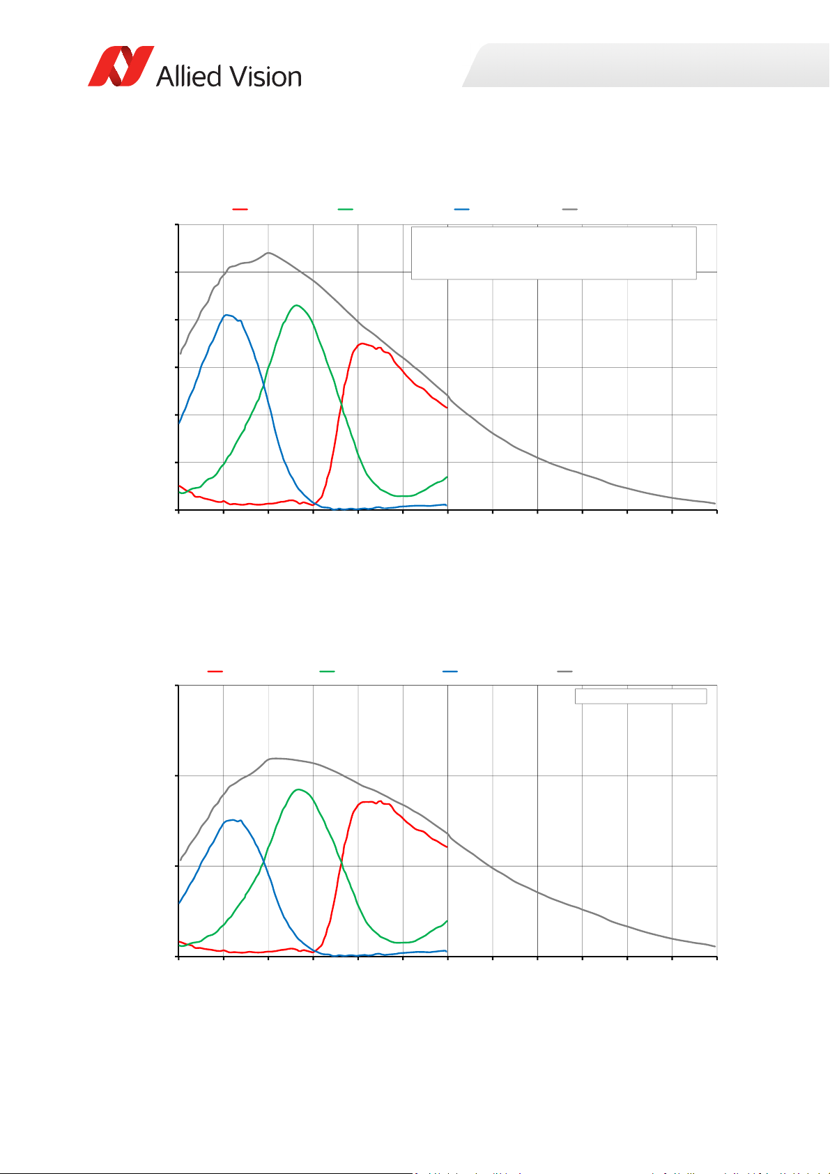
Absolute QE
0%
10%
20%
30%
40%
50%
60%
400 450 500 550 600 650 700 750 800 850 900 950 1000
QuantumEfficiency[%]
Wavelength[nm]
SonyICX625absoluteQE
AllmeasurementsweredonewithoutprotectionglassorIRcutfilter.
Withprotectionglassorfilters,quantumefficiency(QE)decreasesbyapproximately10%.
TheuncertaintyinmeasurementoftheQEis+/Ͳ 10.25%.
Thevaluesaretypicalandaresubjecttominorvariations.
RedQE GreenQE BlueQE MonochromeQE
0.0000
0.1000
0.2000
0.3000
400 450 500 550 600 650 700 750 800 850 900 950 1000
SpectralResponse[A/W]
Wavelength[nm]
SonyICX625spectralresponse
RedResponse GreenResponse BlueResponse MonochromeResponse
Specifications
Figure 31: Prosilica GT2450, GT2450C (Sony ICX625) absolute QE
Spectral response
Figure 32: Prosilica GT2450, GT2450C (Sony ICX625) spectral response
75Prosilica GT Technical Manual V2.9.0
Page 76
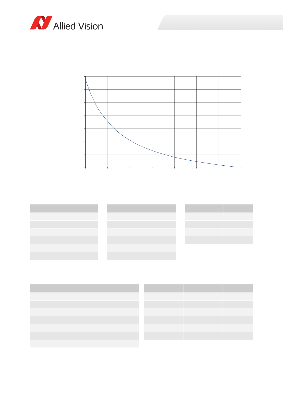
ROI frame rate
15
25
35
45
55
65
75
85
0 300 600 900 1200 1500 1800 2100
Framerate[fps]
ROIheight[pixels]
Specifications
Figure 33: Frame rate as a function of ROI height [width=2448 pixels]
Height in pixels Frame rate Height in pixels Frame rate Height in pixels Frame rate
2050 15 1000 25.9 50 74.7
2000 15.3 800 30 20 79.4
1800 16.7 600 35.7 10 81.1
1600 18.4 400 44.1 2 82.5
1400 20.3 200 57.5
1200 22.7 100 67.9
Table 34: Frame rate as a function of ROI height [width=2448 pixels]
The following table shows how binning affects frame rate.
BinningVertical Height in pixels Frame rate BinningVertical Height in pixels Frame rate
2 1025 25.4 9 227 54.8
3 683 33.1 10 205 56.6
4 512 38.9 11 186 58.2
5 410 43.4 12 170 59.6
6 341 47.1 13 157 60.8
7 292 50.2 14 146 61.8
8 256 52.7
Table 35: Frame rate as a function of ROI height with vertical binning enabled
76Prosilica GT Technical Manual V2.9.0
Page 77
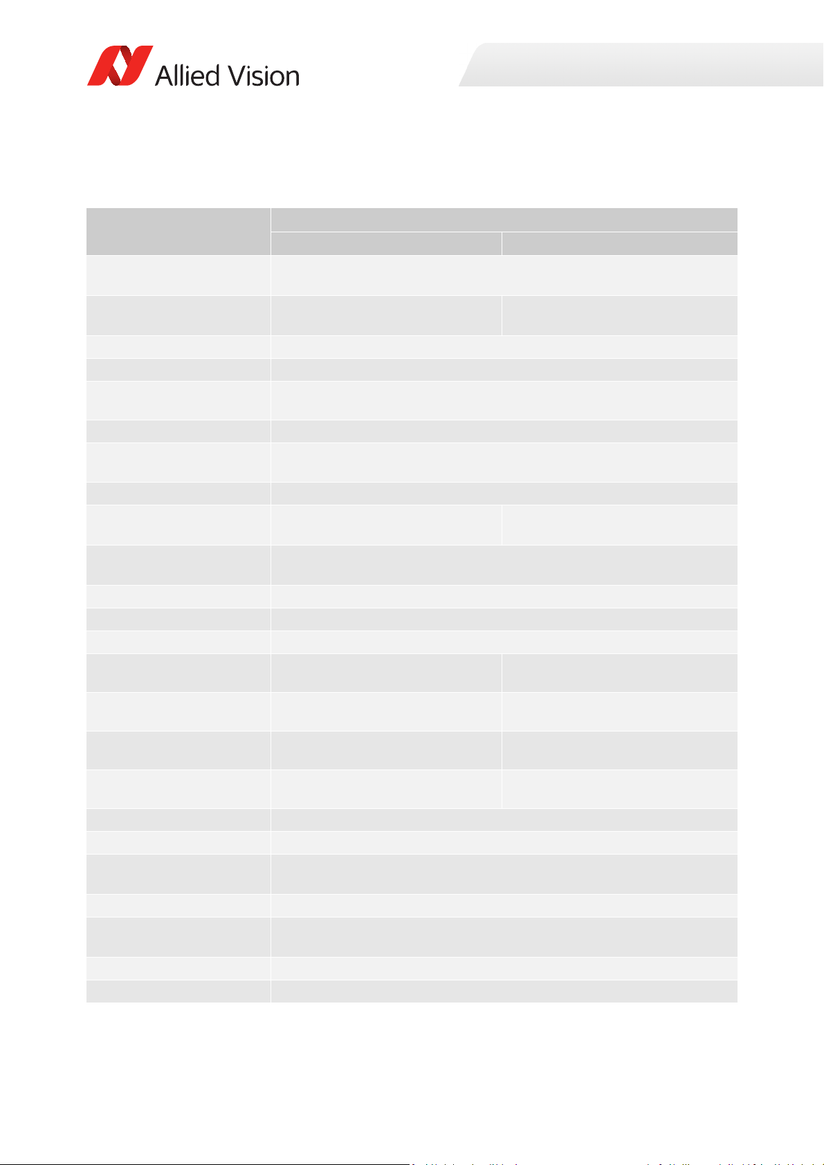
Prosilica GT2750, GT2750C
Specification
Feature
Resolution 2750 (H) × 2200 (V)
Sensor Sony ICX694ALG with EXview HAD
CCD II™ technology
Sensor type
Shutter type Global
Sensor size
Pixel size 4.54 μm × 4.54 μm
Lens mount
Housing Extended format
Optical filter Standard: No optical filter
Optional: See the Modular Concept
Maximum frame rate at full
resolution
Maximum image bit depth
Image buffer
StreamHoldCapacity
Monochrome formats
Color formats (YUV)
Color formats (RGB)
RAW formats
Exposure time control
Gain control
Binning Horizontal: 1 to 8 columns
Decimation X/Y Horizontal and vertical: 1, 2, 4, 8 factor
Sensor taps Four-tap
TTL (non-isolated) I/Os
Opto-isolated I/Os
Mono8, Mono12, Mono12Packed,
Mono14
N/A YUV411Packed, YUV422Packed,
N/A RGB8Packed, BGR8Packed,
N/A BayerGR8, BayerGR12,
Prosilica GT2750 Prosilica GT2750C
6.1 MP
Sony ICX694AQG with EXview HAD
CCD II™ technology
Interline CCD, Progressive Scan
Typ e 1
15.989 mm diagonal
Standard: C-Mount
Optional: See the
Four-tap mode: 19.8 fps
One-tap mode: 5.7 fps
14-bit (monochrome), 12-bit (color)
Up to 21 frames at full resolution
10 µs to 26.8 s, 1 µs increments
0 to 33 dB; 1 dB increments
Vertical: 1 to 8 rows
Single-tap switchable in Vimba Viewer 2.0 or later
1 input, 2 outputs
1 input, 2 outputs
Modular Concept
Standard: IRC30 IR cut filter
Optional: See the Modular Concept
128 MB
Mono8
YUV444Packed
RGBA8Packed, BGRA8Packed
BayerRG12Packed
Specifications
Table 36: Prosilica GT2750, GT2750C model specifications
77Prosilica GT Technical Manual V2.9.0
Page 78
Specification
Specifications
Feature
RS232
Voltage Requirements
Power consumption
Trigger latency
Prosilica GT2750 Prosilica GT2750C
1 TxD, 1 RxD
7 to 25 VDC; PoE
5.4 W @ 12 VDC; 6.6 W PoE
2.2 µs
Trigger jitter ±20 ns
Propagation delay (tpd)
Operating temperature
Storage temperature
Operating humidity
Body dimensions (L × W × H)
Mass (typical)
Interface
Interface standard
30 ns for non-isolated I/O; 70 ns for isolated I/O
-20 °C to +60 °C ambient temperature (without condensation)
-20 °C to +70 °C ambient temperature (without condensation)
20 to 80% non-condensing
92 × 53.3 × 33 mm
224 g
IEEE 802.3 1000BASE-T (Gigabit Ethernet), IEEE 802.3af (PoE)
GigE Vision® Standard V1.2
Camera control standard GenICam SFNC V1.2.1
Regulations
CE, RoHS, REACH, WEEE, FCC, ICES
Temperature monitoring Available for main board and sensor board
Resolution: 0.031; Accuracy: ±1
°C
Table 36: Prosilica GT2750, GT2750C model specifications (continued)
78Prosilica GT Technical Manual V2.9.0
Page 79
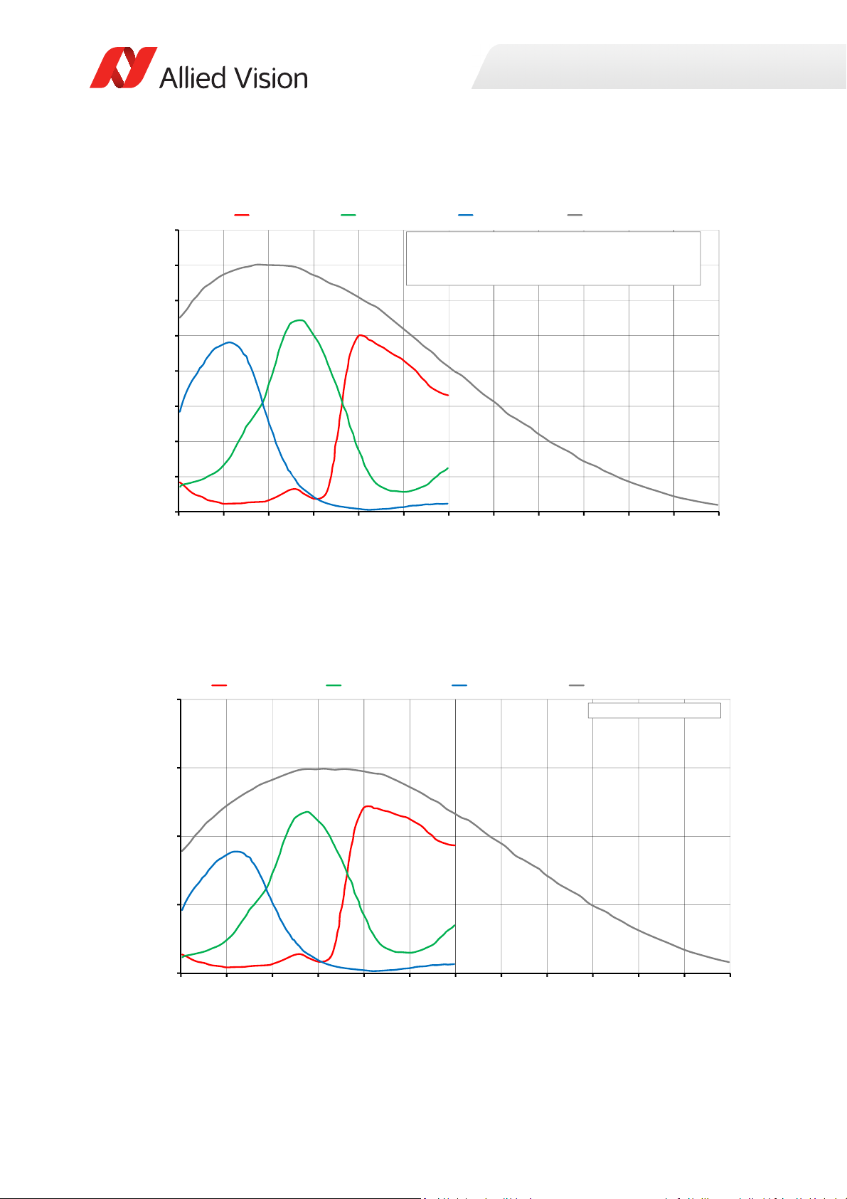
Absolute QE
0%
10%
20%
30%
40%
50%
60%
70%
80%
400 450 500 550 600 650 700 750 800 850 900 950 1000
QuantumEfficiency[%]
Wavelength[nm]
SonyICX694absoluteQE
AllmeasurementsweredonewithoutprotectionglassorIRcutfilter.
Withprotectionglassorfilters,quantumefficiency(QE)decreasesbyapproximately10%.
TheuncertaintyinmeasurementoftheQEis+/Ͳ 10.25%.
Thevaluesaretypicalandaresubjecttominorvariations.
RedQE GreenQE BlueQE MonochromeQE
0.0000
0.1000
0.2000
0.3000
0.4000
400 450 500 550 600 650 700 750 800 850 900 950 1000
SpectralResponse[A/W]
Wavelength[nm]
SonyICX694spectralresponse
RedResponse GreenResponse BlueResponse MonochromeResponse
Specifications
Figure 34: Prosilica GT2750, GT2750 (Sony ICX694) absolute QE
Spectral response
Figure 35: Prosilica GT2750, GT2750C (Sony ICX694) spectral response
79Prosilica GT Technical Manual V2.9.0
Page 80
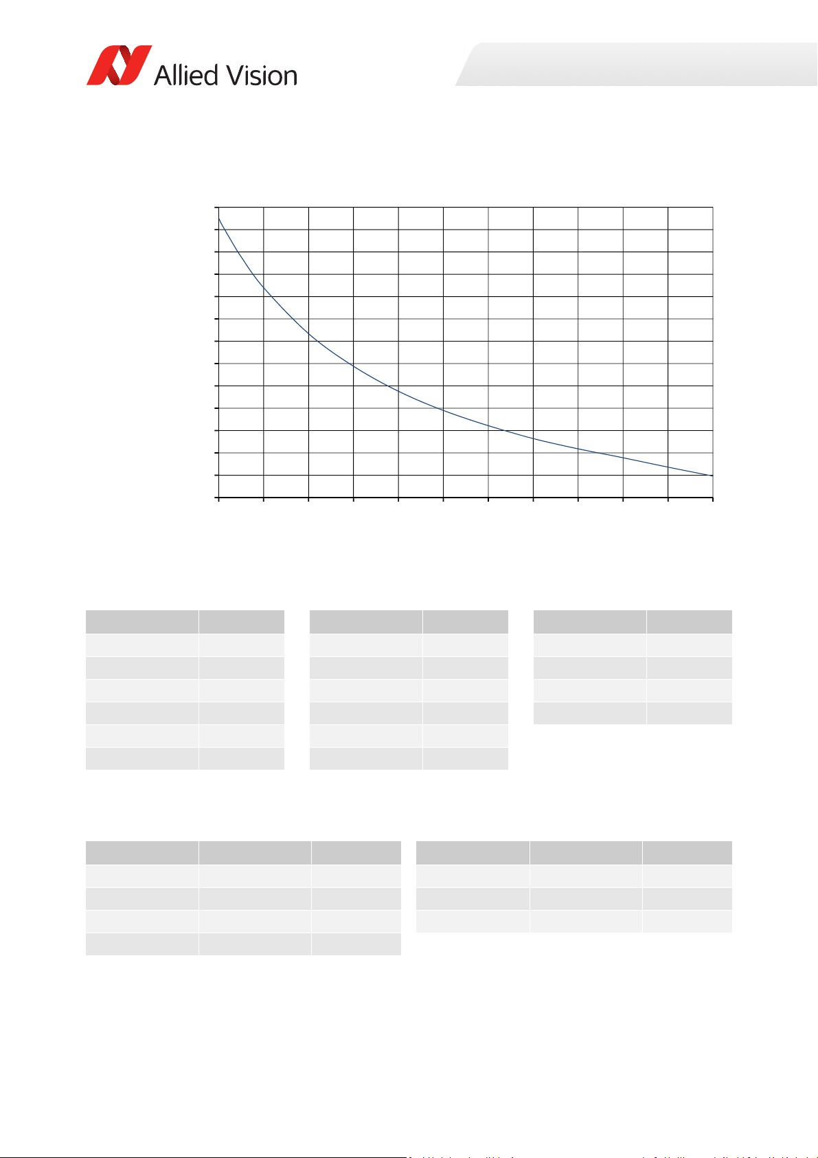
ROI frame rate
15
20
25
30
35
40
45
50
55
60
65
70
75
80
0 200 400 600 800 1000 1200 1400 1600 1800 2000 2200
Framerate[fps]
ROIheight[pixels]
Specifications
Figure 36: Frame rate as a function of ROI height [width=2750 pixels]
Height in pixels Frame rate Height in pixels Frame rate Height in pixels Frame rate
2200 19.8 1000 34.5 50 73
2000 21.8 800 38.8 20 75.6
1800 23.9 600 44.4 10 76.5
1600 25.9 400 51.7 2 77.4
1400 28.2 200 62
1200 31.1 100 68.9
Table 37: Frame rate as a function of ROI height [width=2750 pixels]
BinningVertical Height in pixels Frame rate BinningVertical Height in pixels Frame rate
2 1100 37.0 6 366 77.4
3 732 50.2 7 314 83.8
4 550 60.9 8 274 88.9
5 440 70.0
The following table shows how binning affects frame rate.
Table 38: Frame rate as a function of ROI height with vertical binning enabled
80Prosilica GT Technical Manual V2.9.0
Page 81
Prosilica GT3300, GT3300C
Specification
Feature
Resolution 3296 (H) × 2472 (V)
Sensor ON Semi KAI-08050 TRUESENSE Gen 2
Sensor Type
Shutter type Global
Sensor size
Pixel size 5.5 μm × 5.5 μm
Lens mount
Housing Extended format
Optical filter Standard: No optical filter
Optional: See the Modular Concept
Maximum frame rate at full
resolution
Maximum image bit depth
Image buffer
StreamHoldCapacity
Monochrome formats
Color formats (YUV)
Color formats (RGB)
RAW formats
Exposure time control
Gain control
Binning Horizontal: 1 to 8 columns
Decimation X/Y Horizontal and vertical: 1, 2, 4, 8 factor
Sensor taps Four-tap
TTL (non-isolated) I/Os
Opto-isolated I/Os
Mono8, Mono12, Mono12Packed,
Mono14
N/A YUV411Packed, YUV422Packed,
N/A RGB8Packed, BGR8Packed,
N/A BayerGR8, BayerGR12,
Prosilica GT3300 Prosilica GT3300C
8.1 MP
Interline CCD, Progressive Scan
Typ e 4/3
22.66 mm diagonal
Standard: F-Mount
Optional: See the
Four-tap mode: 14.7 fps
One-tap mode: 4.5 fps
14-bit (monochrome), 12-bit (color)
Up to 16 frames at full resolution
10 µs to 26.8 s, 1 µs increments
0 to 32 dB; 1 dB increments
Vertical: 1 to 8 rows
Single-tap switchable in Vimba Viewer 2.0 or later
1 input, 2 outputs
1 input, 2 outputs
Modular Concept
Standard: IRC30 IR cut filter
Optional: See the Modular Concept
128 MB
Mono8
YUV444Packed
RGBA8Packed, BGRA8Packed
BayerRG12Packed
Specifications
Table 39: Prosilica GT3300, GT3300C model specifications
81Prosilica GT Technical Manual V2.9.0
Page 82
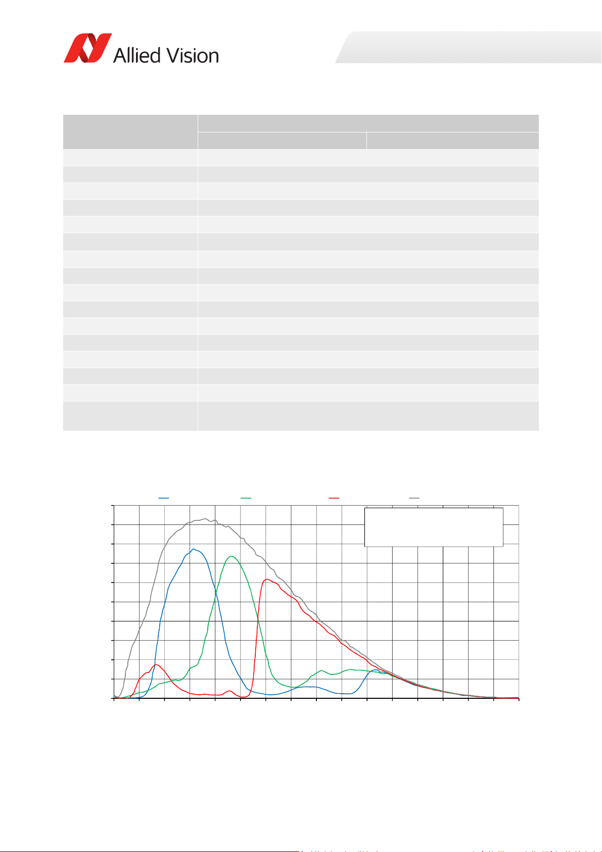
Specification
0%
5%
10%
15%
20%
25%
30%
35%
40%
45%
50%
300 350 400 450 500 550 600 650 700 750 800 850 900 950 1000 1050 1100
QuantumEfficiency
Wavelength[nm]
ONSemiconductorKAIͲ08050absoluteQE
ONSemiconductorGen2CFAmaterialforco lorsensors
Note:MeasuredwithARcoatedcoverglass.
TheuncertaintyofmeasurementoftheQEis+/Ͳ 10.25%.
Thevaluesaretypicalandaresubjecttominorvariations.
BlueQE GreenQE RedQE MonochromeQE
Specifications
Feature
RS232
Voltage requirements
Power consumption
Trigger latency
Prosilica GT3300 Prosilica GT3300C
1 TxD, 1 RxD
7 to 25 VDC; PoE
5.6 W @ 12 VDC; 6.9 W PoE
2.2 µs
Trigger jitter ±20 ns
Propagation delay (tpd)
Operating temperature
Storage temperature
Operating humidity
Body dimensions (L × W × H)
Mass (typical)
Interface
Interface standard
30 ns for non-isolated I/O; 70 ns for isolated I/O
-20 to +60 °C ambient temperature (without condensation)
-20 to +70 °C ambient temperature (without condensation)
20 to 80% non-condensing
121 × 59.7 × 59.7 mm
314 g
IEEE 802.3 1000BASE-T (Gigabit Ethernet), IEEE 802.3af (PoE)
GigE Vision® Standard V1.2
Camera control standard GenICam SFNC V1.2.1
Regulations
CE, RoHS, REACH, WEEE, FCC, ICES
Temperature monitoring Available for main board and sensor board.
Resolution: 0.031; Accuracy: ±1 °C
Table 39: Prosilica GT3300, GT3300C model specifications (continued)
Absolute QE
Figure 37: Prosilica GT3300, GT3300C (ON Semi KAI-08050 Gen 2) absolute QE
82Prosilica GT Technical Manual V2.9.0
Page 83
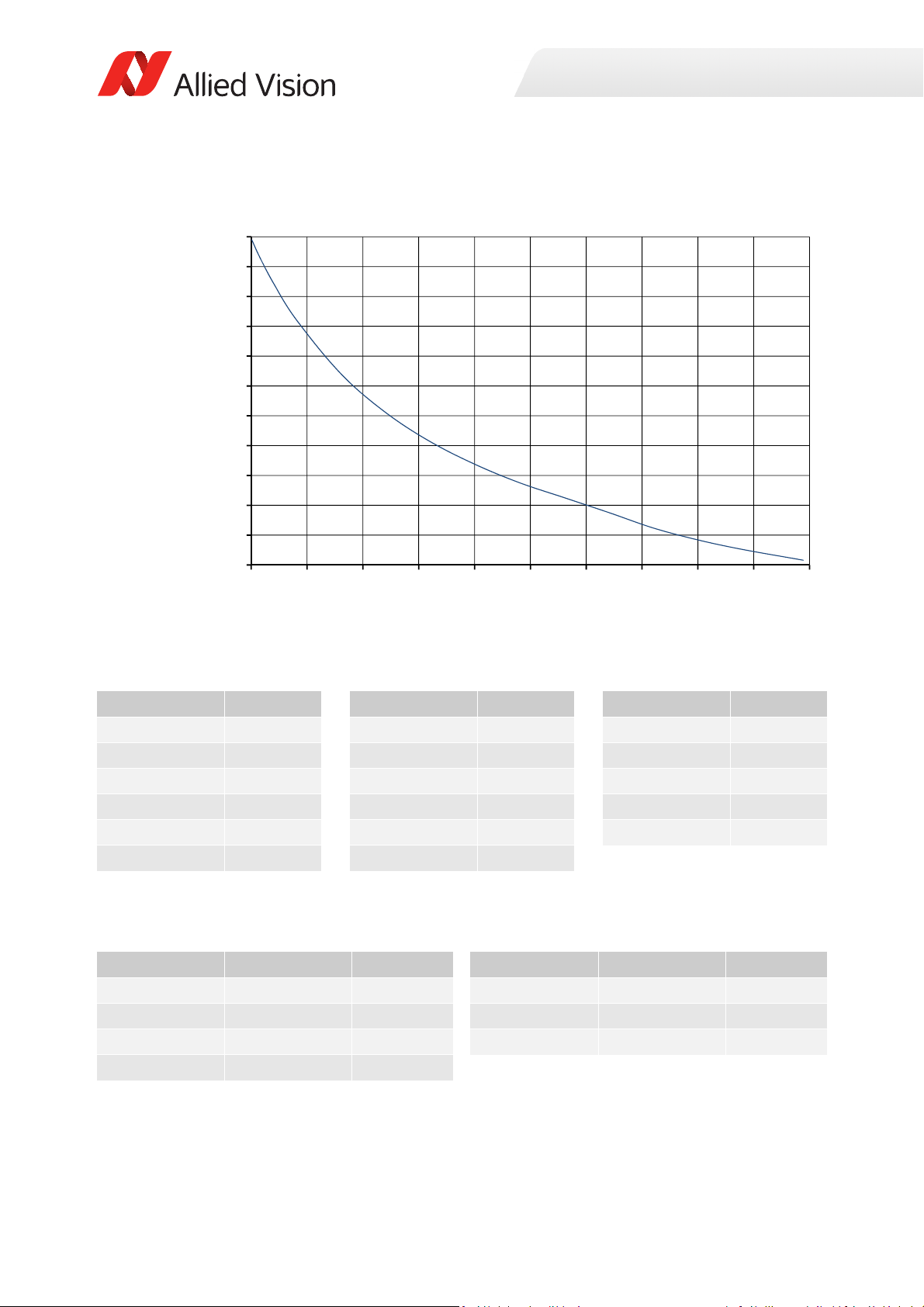
ROI frame rate
14
19
24
29
34
39
44
49
54
59
64
69
0 250 500 750 1000 1250 1500 1750 2000 2250 2500
Framerate[fps]
ROIheight[pixels]
Specifications
Figure 38: Frame rate as a function of ROI height [width=3296 pixels]
Height in pixels Frame rate Height in pixels Frame rate Height in pixels Frame rate
2472 14.8 1200 27.8 100 61.2
2200 16.6 1000 30.9 50 64.7
2000 18.2 800 34.7 20 67
1800 20.2 600 39.6 10 67.9
1600 22.8 400 46.1 2 68.5
1400 25.3 200 55.2
Table 40: Frame rate as a function of ROI height [width=3296 pixels]
The following table shows how binning affects frame rate.
BinningVertical Height in pixels Frame rate BinningVertical Height in pixels Frame rate
2 1236 29.4 6 412 69.5
3 824 43.1 7 352 75.8
4 618 53.2 8 308 81.4
5 494 62.0
Table 41: Frame rate as a function of ROI height with vertical binning enabled
83Prosilica GT Technical Manual V2.9.0
Page 84
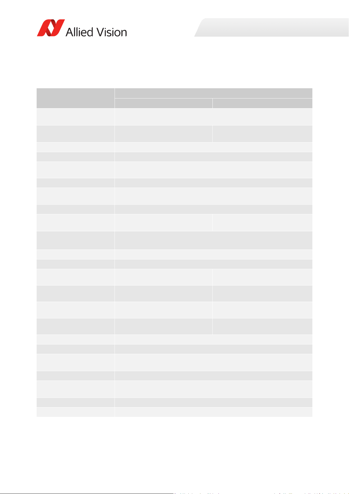
Prosilica GT3400, GT3400C
Specification
Feature
Resolution 3384 (H) × 2704 (V)
Sensor Sony ICX814ALG with EXview HAD
II™ technology
Sensor type
Shutter type Global
Sensor size
Pixel size 3.69 μm × 3.69 μm
Lens mount
Housing Extended format
Optical filter Standard: No optical filter
Optional: See the Modular Concept
Maximum frame rate at full
resolution
Maximum image bit depth
Image buffer
Monochrome formats
Color formats (YUV
Color formats (RGB)
RAW formats
Exposure time control 10 µs to 26.8 s, 1 µs increments
Gain control
Binning Horizontal: 1 to 8 columns
Decimation X/Y Horizontal and vertical: 1, 2, 4, 8 factor
Sensor taps Four-tap
TTL (non-isolated) I/Os
Opto-isolated I/Os
Mono8, Mono12, Mono12Packed,
Mono14
N/A YUV411Packed, YUV422Packed,
N/A RGB8Packed, BGR8Packed,
N/A BayerRG8, BayerRG12,
Prosilica GT3400 Prosilica GT3400C
9.2 MP
Sony ICX814AQG with EXview HAD
II™ technology
Interline CCD, Progressive Scan
Typ e 1
15.972 mm diagonal
Standard: C-Mount
Optional: See the
Four-tap mode: 13.2 fps (14 fps burst mode1)
One-tap mode: 3.8 fps
14-bit (monochrome), 12-bit (color)
0 to 31 dB; 1 dB increments
Vertical: 1 to 8 rows
Single-tap switchable in Vimba Viewer 2.0 or later
1 input, 2 outputs
1 input, 2 outputs
Modular Concept
Standard: IRC30 IR cut filter
Optional: See the Modular Concept
128 MB
Mono8
YUV444Packed
RGBA8Packed, BGRA8Packed
BayerRG12Packed
Specifications
Table 42: Prosilica GT3400, GT3400C model specifications
84Prosilica GT Technical Manual V2.9.0
Page 85
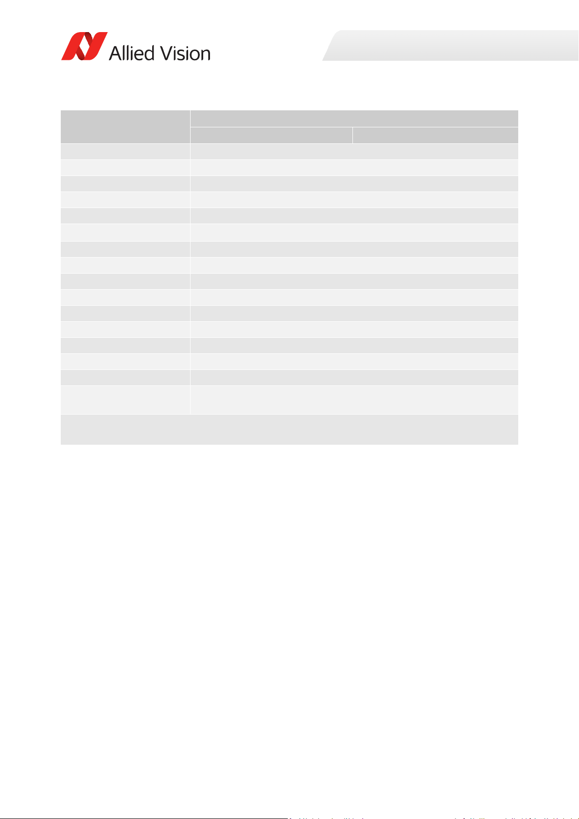
Specification
Specifications
Feature
RS232
Voltage requirements
Power consumption
Prosilica GT3400 Prosilica GT3400C
1 TxD, 1 RxD
7 to 25 VDC; PoE
5.4 W @ 12 VDC; 6.6 W PoE
Trigger latency 2.5 µs
Trigger jitter ±20 ns
Propagation delay (tpd)
Operating temperature
Storage temperature
Operating humidity
Body dimensions (L × W × H)
Mass (typical)
Interface
Interface standard
30 ns for non-isolated I/O; 70 ns for isolated I/O
-20 °C to +60 °C ambient temperature (without condensation)
-20 °C to +70 °C ambient temperature (without condensation)
20 to 80% non-condensing
92 × 53.3 × 33 mm
224 g
IEEE 802.3 1000BASE-T (Gigabit Ethernet), IEEE 802.3af (PoE)
GigE Vision® Standard V1.2
Camera control standard GenICam SFNC V1.2.1
Regulations
CE, RoHS, REACH, WEEE, FCC, ICES
Temperature monitoring Available for main board and sensor board.
Resolution: 0.031; Accuracy: ±1 °C
1
GigE host controller card with jumbo packets is required. See Hardware Selection for Allied Vision GigE
Cameras application note for a list of recommended GigE host controller cards.
Table 42: Prosilica GT3400, GT3400C model specifications (continued)
85Prosilica GT Technical Manual V2.9.0
Page 86
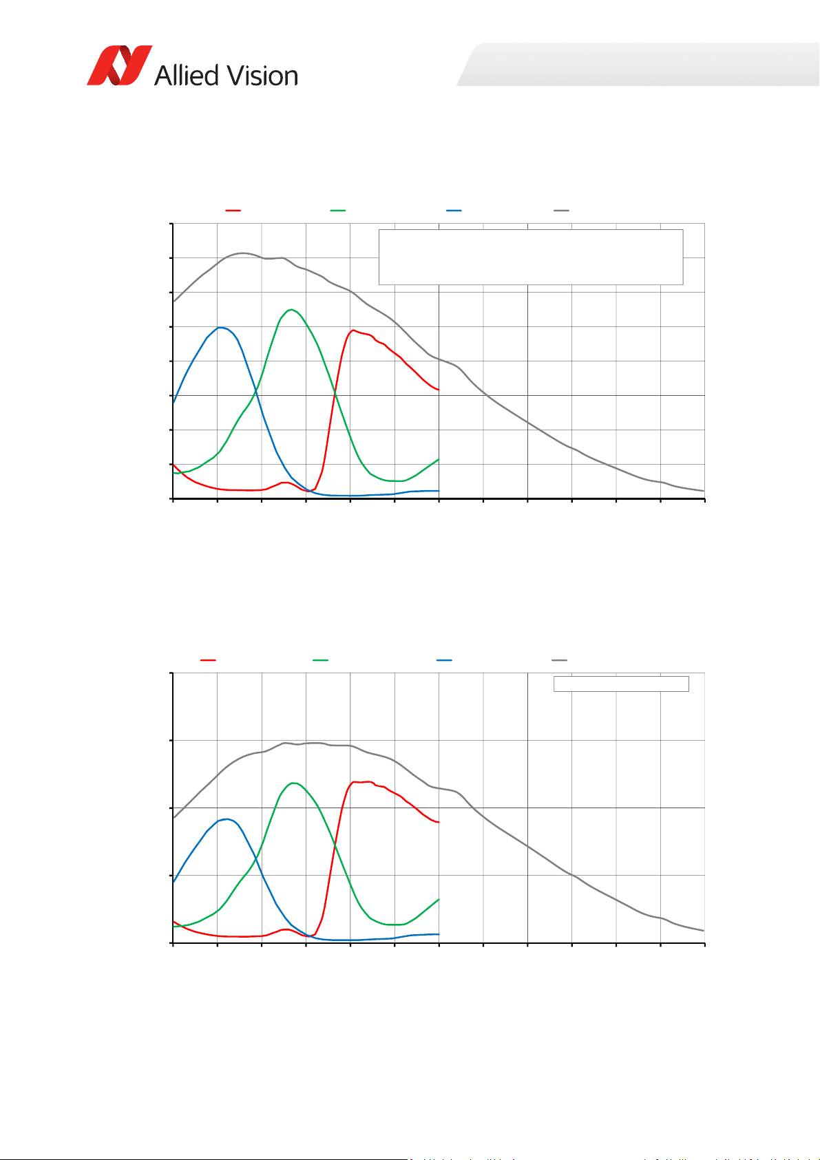
Absolute QE
0%
10%
20%
30%
40%
50%
60%
70%
80%
400 450 500 550 600 650 700 750 800 850 900 950 1000
QuantumEfficiency[%]
Wavelength[nm]
SonyICX814absoluteQE
AllmeasurementsweredonewithoutprotectionglassorIRcutfilter.
Withprotectionglassorfilters,quantumefficiency(QE)decreasesbyapproximately10%.
TheuncertaintyinmeasurementoftheQEis+/Ͳ 10.25%.
Thevaluesaretypicalandaresubjecttominorvariations.
RedQE GreenQE BlueQE MonochromeQE
0.0000
0.1000
0.2000
0.3000
0.4000
400 450 500 550 600 650 700 750 800 850 900 950 1000
SpectralResponse[A/W]
Wavelength[nm]
SonyICX814spectralresponse
RedResponse GreenResponse BlueResponse MonochromeResponse
Specifications
Figure 39: Prosilica GT3400, GT3400C (Sony ICX814) absolute QE
Spectral response
Figure 40: Prosilica GT3400B, GT3400C (Sony ICX814) spectral response
86Prosilica GT Technical Manual V2.9.0
Page 87
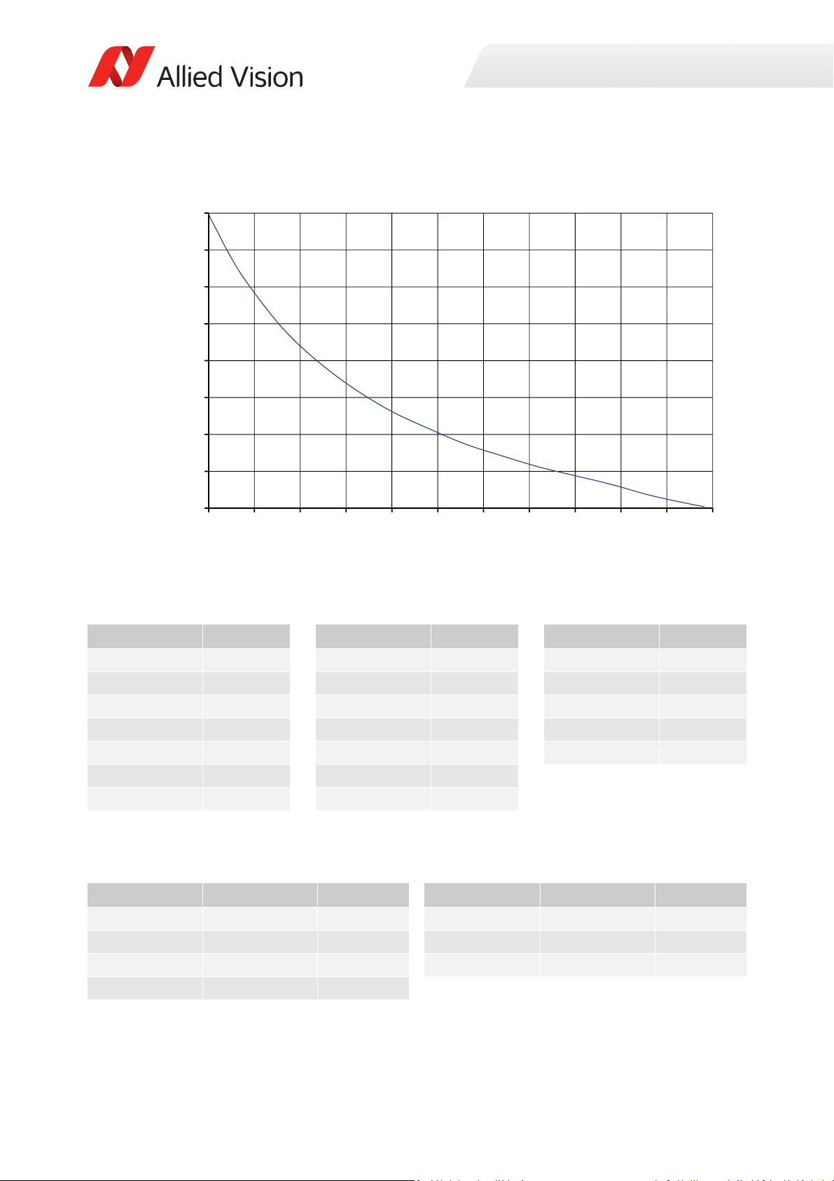
ROI frame rate
13
18
23
28
33
38
43
48
53
0 250 500 750 1000 1250 1500 1750 2000 2250 2500 2750
Framerate[fps]
ROIheight[pixels]
Specifications
Figure 41: Frame rate as a function of ROI height [width=3384 pixels]
Height in pixels Frame rate Height in pixels Frame rate Height in pixels Frame rate
2704 13.2 1400 21.7 100 48
2600 13.7 1200 23.8 50 50.4
2400 14.8 1000 26.1 20 51.8
2200 16.2 800 29.1 10 52.3
2000 17.4 600 32.8 2 52.8
1800 18.6 400 37.5
1600 20.1 200 43.9
Table 43: Frame rate as a function of ROI height [width=3384 pixels]
The following table shows how binning affects frame rate.
BinningVertical Height in pixels Frame rate BinningVertical Height in pixels Frame rate
2 1352 25.1 6 450 52.8
3 900 34.1 7 386 57.2
4 676 41.4 8 338 61.0
5 540 47.6
Table 44: Frame rate as a function of ROI height with vertical binning enabled
87Prosilica GT Technical Manual V2.9.0
Page 88
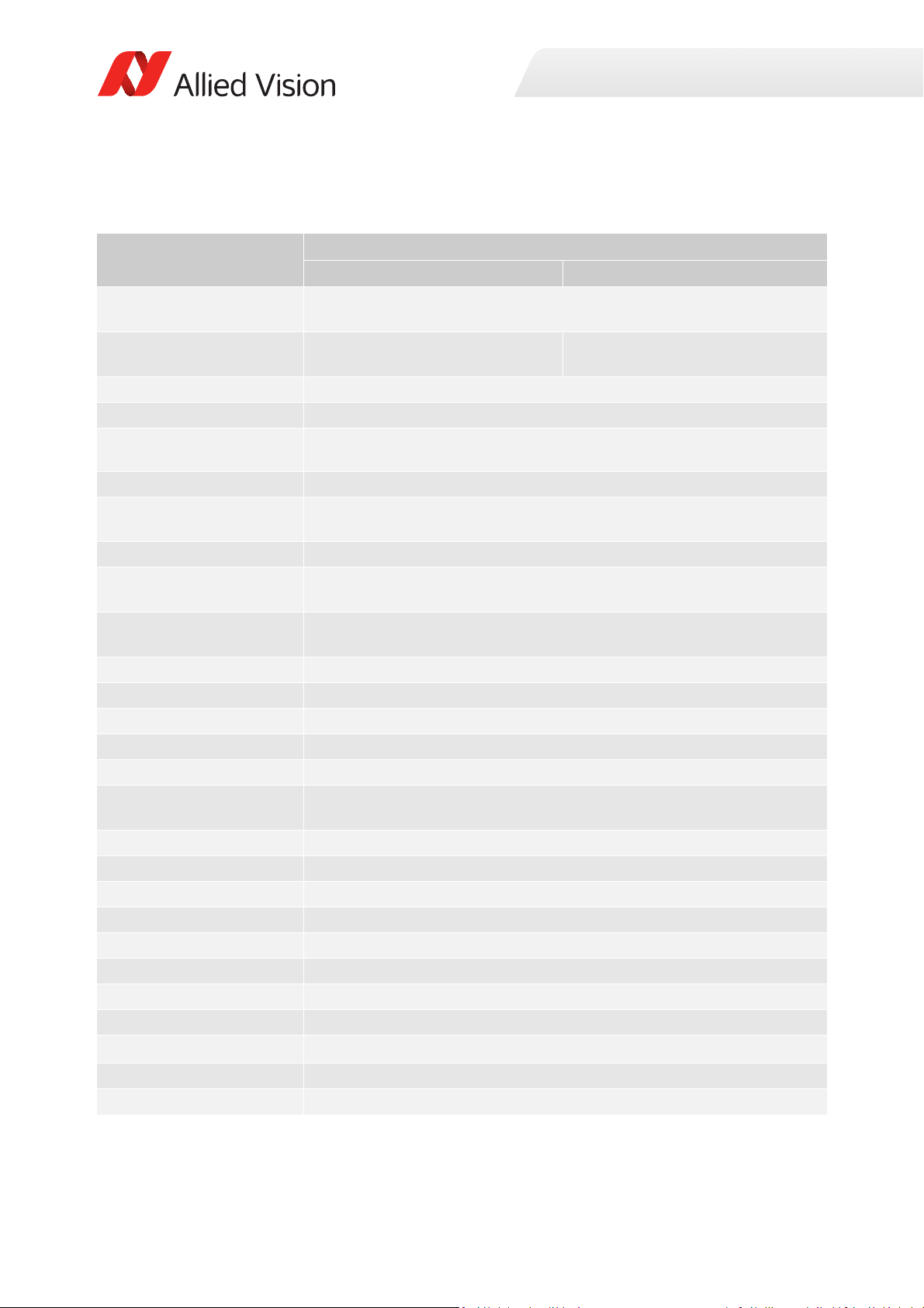
Prosilica GT4090, GT4090NIR
Specification
Feature
Resolution 4096 (H) × 3072 (V)
Sensor ON Semi PYTHON 12K
(NOIP1SN012KA)
Sensor type
Shutter type Global
Sensor size
Pixel size 4.5 μm × 4.5 μm
Lens mount
Housing Large format
Optical filter Standard: No optical filter
Maximum frame rate at full
resolution
Maximum image bit depth
Image buffer
Monochrome formats Mono8, Mono10
Exposure control
Gain control
Binning Horizontal: 1 to 8 columns
Decimation X/Y Horizontal and vertical: 1, 2, 4, 8 factor
TTL (non-isolated) I/Os
Opto-isolated I/Os
RS232
Voltage requirements
Power consumption
Trigger latency
Trigger jitter ±100 ns
Propagation delay (tpd)
1
Prosilica GT4090 Prosilica GT4090NIR
12.5 MP
ON Semi PYTHON 12K
(NOIP1FN012KA)
CMOS
Typ e 4/3
23.04 mm diagonal
Standard: F-Mount
Optional: See the
Optional: See the Modular Concept
9.58 fps (Mono8); 10.15 fps burst mode
4.79 fps (Mono10); 10.15 fps burst mode
100 µs to 1 s, 1 µs increments
Vertical: 1 to 8 rows
1 input, 2 outputs
1 input, 2 outputs
7 to 25 VDC; PoE
4.96 W @ 12 VDC; 6.7 W PoE
30 ns for non-isolated I/O; 70 ns for isolated I/O
Modular Concept
10-bit
128 MB
0 to 22 dB
1 TxD, 1 RxD
25.8 µs
Specifications
Operating temperature
Storage temperature
-20 °C to +50 °C ambient temperature (without condensation)
-20 °C to +70 °C ambient temperature (without condensation)
Table 45: Prosilica GT4090, GT4090NIR model specifications
88Prosilica GT Technical Manual V2.9.0
Page 89
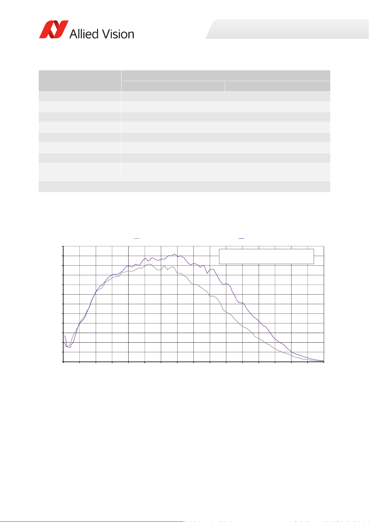
Specification
0
5
10
15
20
25
30
35
40
45
50
55
60
300 350 400 450 500 550 600 650 700 750 800 850 900 950 1000 1050 1100
Quantum Eĸciency [%]
Wavelength [nm]
ON Semiconductor PYTHON 12K, 16K, 25K absolute QE
The uncertainty of measurement of the QE is +/- 10.25%.
The values are typical and are subject to minor variaƟons.
Monochrome QE
NIR QE
Specifications
Feature
Operating humidity
Body dimensions (L × W × H)
Mass
Interface
Interface standard
Prosilica GT4090 Prosilica GT4090NIR
20 to 80% non-condensing
96 × 66 × 53.3 mm
372 g
IEEE 802.3 1000BASE-T (Gigabit Ethernet), IEEE 802.3af (PoE)
GigE Vision® Standard V1.2
Camera control standard GenICam SFNC V1.2.1
Regulations
CE, RoHS, REACH, WEEE, FCC, ICES
Temperature monitoring Available for main board and sensor board.
Resolution: 0.031; Accuracy: ±1 °C
1
EF lens control is only supported for cameras with EF lens mount (order option -18).
Table 45: Prosilica GT4090, GT4090NIR model specifications
Absolute QE
Figure 42: Prosilica GT4090, GT4090NIR (ON Semi PYTHON 12K) absolute QE
89Prosilica GT Technical Manual V2.9.0
Page 90
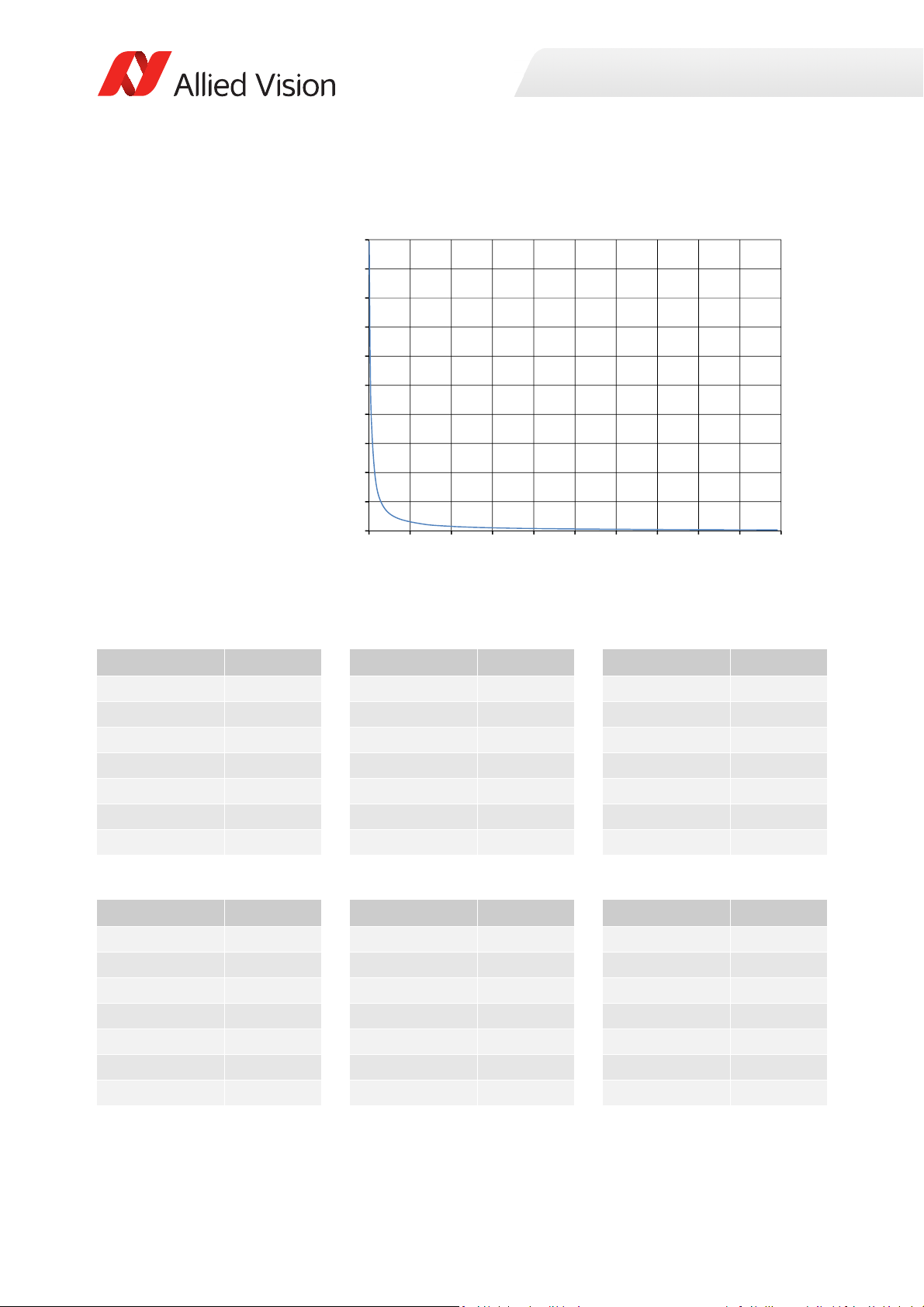
ROI frame rate
0
310
620
930
1240
1550
1860
2170
2480
2790
3100
0 310 620 930 1240 1550 1860 2170 2480 2790 3100
Framerate[fps]
ROIheight[pixels]
Specifications
Figure 43: Frame rate as a function of ROI height [width=4096 pixels]
Height in pixels Frame rate Height in pixels Frame rate Height in pixels Frame rate
3072 9.6 1800 16.3 400 72.8
3000 9.8 1600 18.3 200 143.2
2800 10.5 1400 21.0 100 280.5
2600 11.3 1200 24.4 50 538.8
2400 12.3 1000 29.3 20 1122.5
2200 13.4 800 36.6 10 1759.0
2000 14.7 600 48.6 2 3078.8
Table 46: Frame rate as a function of ROI height @ Mono8 [width=4096 pixels]
Height in pixels Frame rate Height in pixels Frame rate Height in pixels Frame rate
3072 4.8 1800 8.2 400 36.6
3000 4.9 1600 9.2 200 72.8
2800 5.3 1400 10.5 100 143.2
2600 5.7 1200 12.3 50 280.5
2400 6.1 1000 14.7 20 641.5
2200 6.7 800 18.3 10 1122.5
2000 7.4 600 24.4 2 3078.8
Table 47: Frame rate as a function of ROI height @ Mono10 [width=4096 pixels]
90Prosilica GT Technical Manual V2.9.0
Page 91
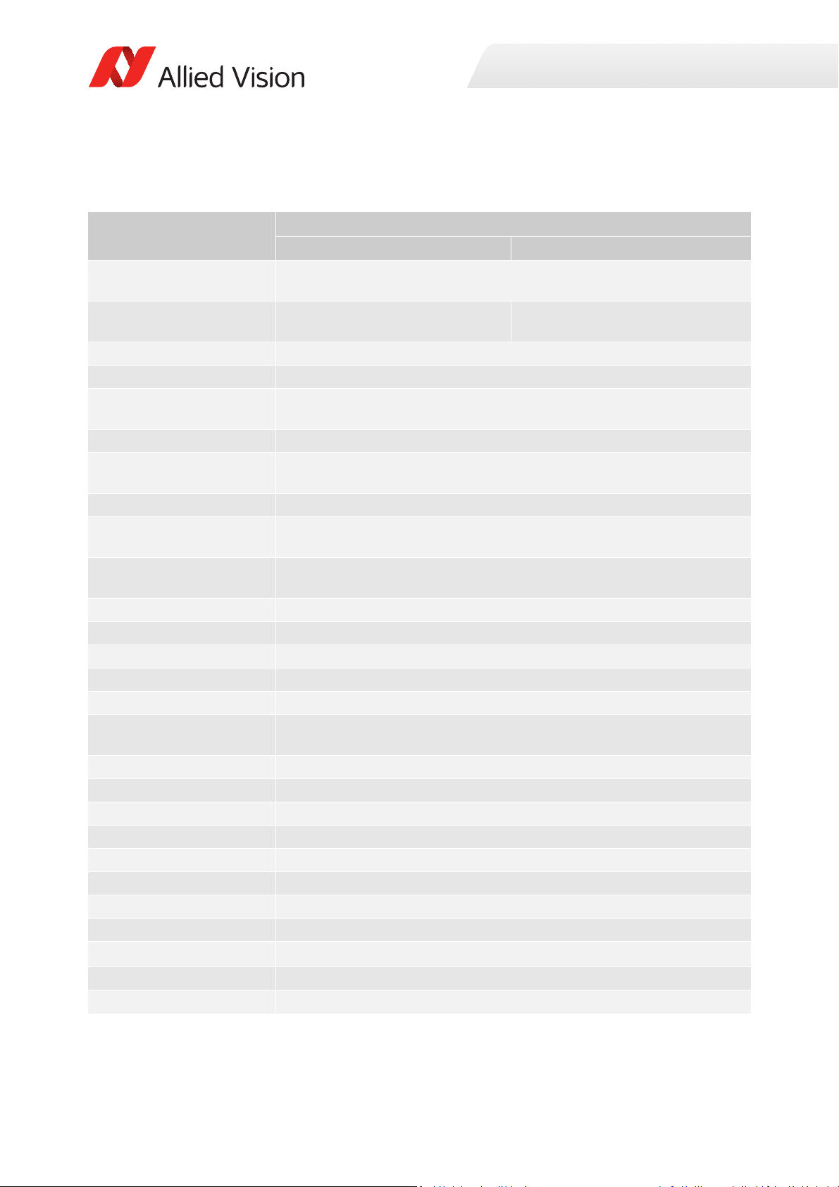
Prosilica GT4096, GT4096NIR
Specification
Feature
Resolution 4096 (H) × 4096 (V)
Sensor ON Semi PYTHON 16K
(NOIP1SN016KA)
Sensor type CMOS
Shutter type Global
Sensor size Type APS-H
Pixel size 4.5 μm × 4.5 μm
Lens mount
Housing Large format
Optical filter Standard: No optical filter
Maximum frame rate at full
resolution
Maximum image bit depth 10-bit
Image buffer 128 MB
Monochrome formats Mono8, Mono10
Exposure control 100 µs to 1 s, 1 µs increments
Gain control 0 to 22 dB
Binning Horizontal: 1 to 8 columns
Decimation X/Y Horizontal and vertical: 1, 2, 4, 8 factor
TTL (non-isolated) I/Os 1 input, 2 outputs
Opto-isolated I/Os 1 input, 2 outputs
RS232 1 TxD, 1 RxD
Voltage requirements 7 to 25 VDC; PoE
Power consumption 5.0 W @ 12 VDC; 6.4 W PoE
Trigger latency 25.8 µs
Trigger jitter ±100 ns
Propagation delay (tpd) 30 ns for non-isolated I/O; 70 ns for isolated I/O
1
Prosilica GT4096 Prosilica GT4096NIR
16.7 MP
ON Semi PYTHON 16K
(NOIP1FN016KA)
26.067 mm diagonal
Standard: F-Mount
Optional: See the Modular Concept
Optional: See the Modular Concept
7.18 fps (Mono8); 7.61 fps burst mode
3.59 (Mono10); 7.61 fps burst mode
Vertical: 1 to 8 rows
Specifications
Operating temperature -20 °C to +50 °C ambient temperature (without condensation)
Storage temperature -20 °C to +70 °C ambient temperature (without condensation)
Table 48: Prosilica GT4096, GT4096NIR model specifications
91Prosilica GT Technical Manual V2.9.0
Page 92
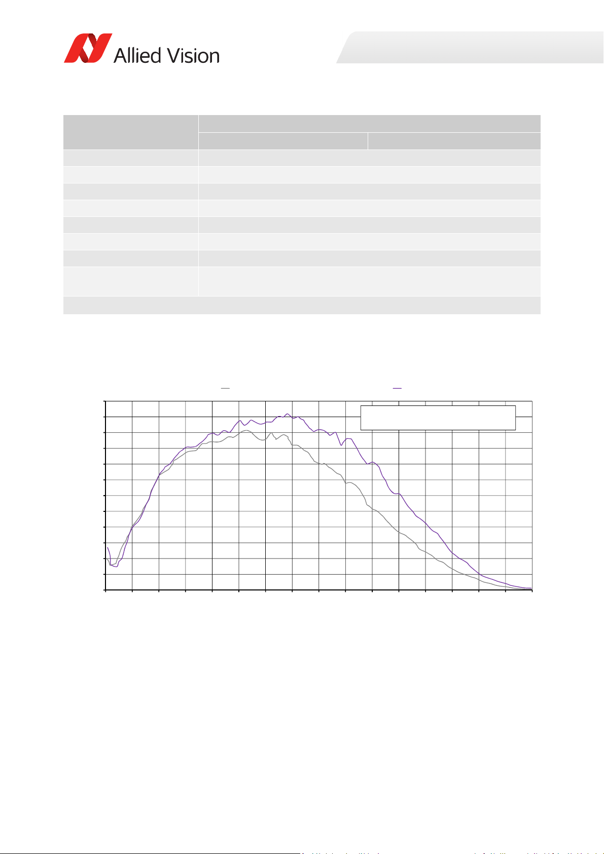
Specification
0
5
10
15
20
25
30
35
40
45
50
55
60
300 350 400 450 500 550 600 650 700 750 800 850 900 950 1000 1050 1100
Quantum Eĸciency [%]
Wavelength [nm]
ON Semiconductor PYTHON 12K, 16K, 25K absolute QE
The uncertainty of measurement of the QE is +/- 10.25%.
The values are typical and are subject to minor variaƟons.
Monochrome QE
NIR QE
Specifications
Feature
Prosilica GT4096 Prosilica GT4096NIR
Operating humidity 20 to 80% non-condensing
Body dimensions (L × W × H) 96 × 66 × 53.3 mm
Mass 372 g
Interface IEEE 802.3 1000BASE-T (Gigabit Ethernet), IEEE 802.3af (PoE)
Interface standard GigE Vision® Standard V1.2
Camera control standard GenICam SFNC V1.2.1
Regulations CE, RoHS, REACH, WEEE, FCC, ICES
Temperature monitoring Available for main board and sensor board.
Resolution: 0.031; Accuracy: ±1 °C
1
EF lens control is only supported for cameras with EF lens mount (order option -18).
Table 48: Prosilica GT4096, GT4096NIR model specifications
Absolute QE
Figure 44: Prosilica GT4096, GT4096NIR (ON Semi PYTHON 16K) absolute QE
92Prosilica GT Technical Manual V2.9.0
Page 93
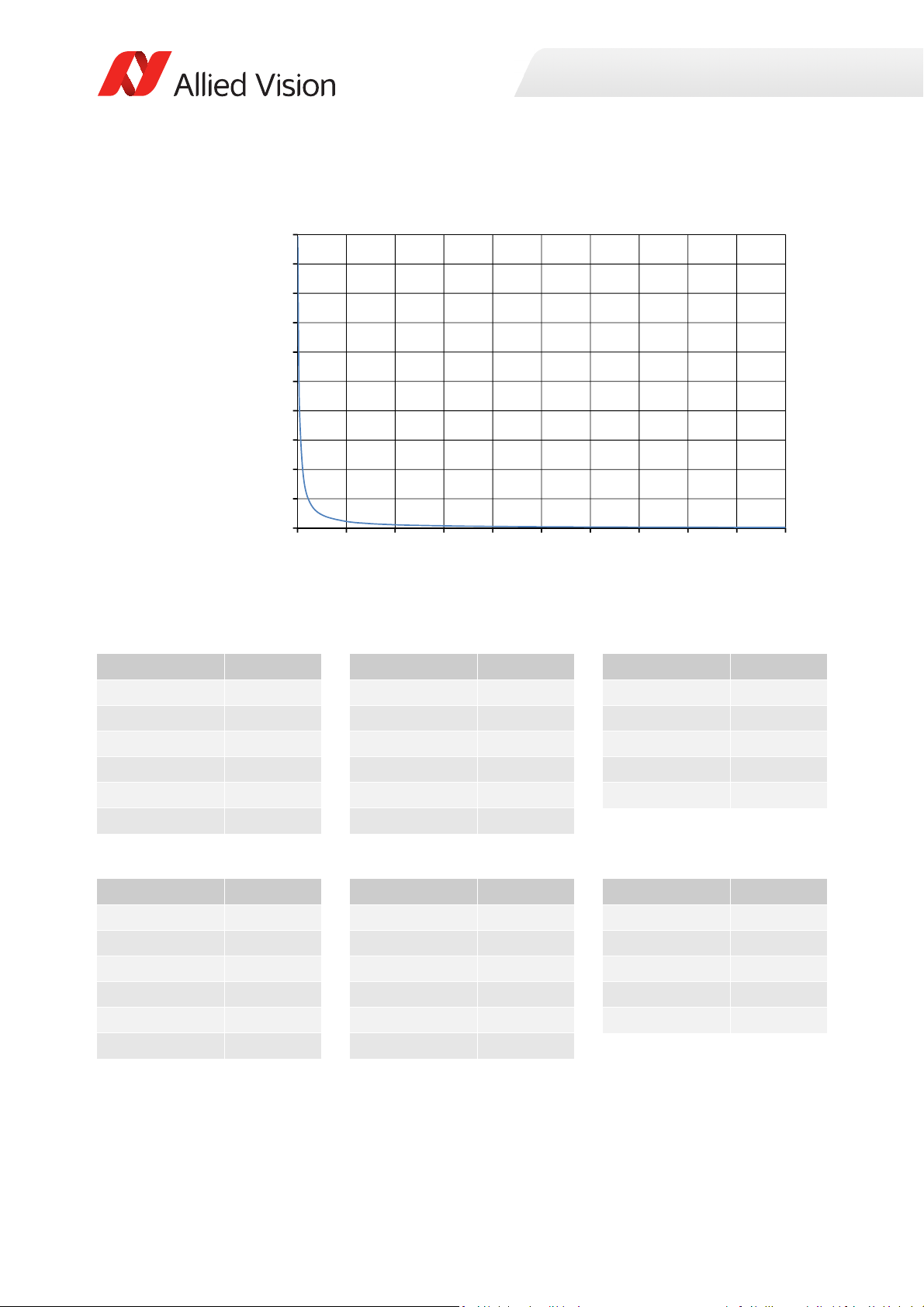
ROI frame rate
0
310
620
930
1240
1550
1860
2170
2480
2790
3100
0 410 820 1230 1640 2050 2460 2870 3280 3690 4100
Framerate[fps]
ROIheight[pixels]
Specifications
Figure 45: Frame rate as a function of ROI height [width=4096 pixels]
Height in pixels Frame rate Height in pixels Frame rate Height in pixels Frame rate
4096 7.2 1200 19.6 100 280.5
4000 7.4 1000 29.3 50 538.8
3500 8.4 800 36.6 20 1122.5
3000 9.8 600 48.6 10 1759.0
2500 11.8 400 72.8 2 3078.8
2000 14.7 200 143.2
Table 49: Frame rate as a function of ROI height @ Mono8 [width=4096 pixels]
Height in pixels Frame rate Height in pixels Frame rate Height in pixels Frame rate
4096 3.6 1200 9.8 100 143.2
4000 3.7 1000 14.7 50 280.5
3500 4.2 800 18.3 20 641.5
3000 4.9 600 24.4 10 1122.5
2500 5.9 400 36.6 2 3078.8
2000 7.4 200 72.8
Table 50: Frame rate as a function of ROI height @ Mono10 [width=4096 pixels]
93Prosilica GT Technical Manual V2.9.0
Page 94
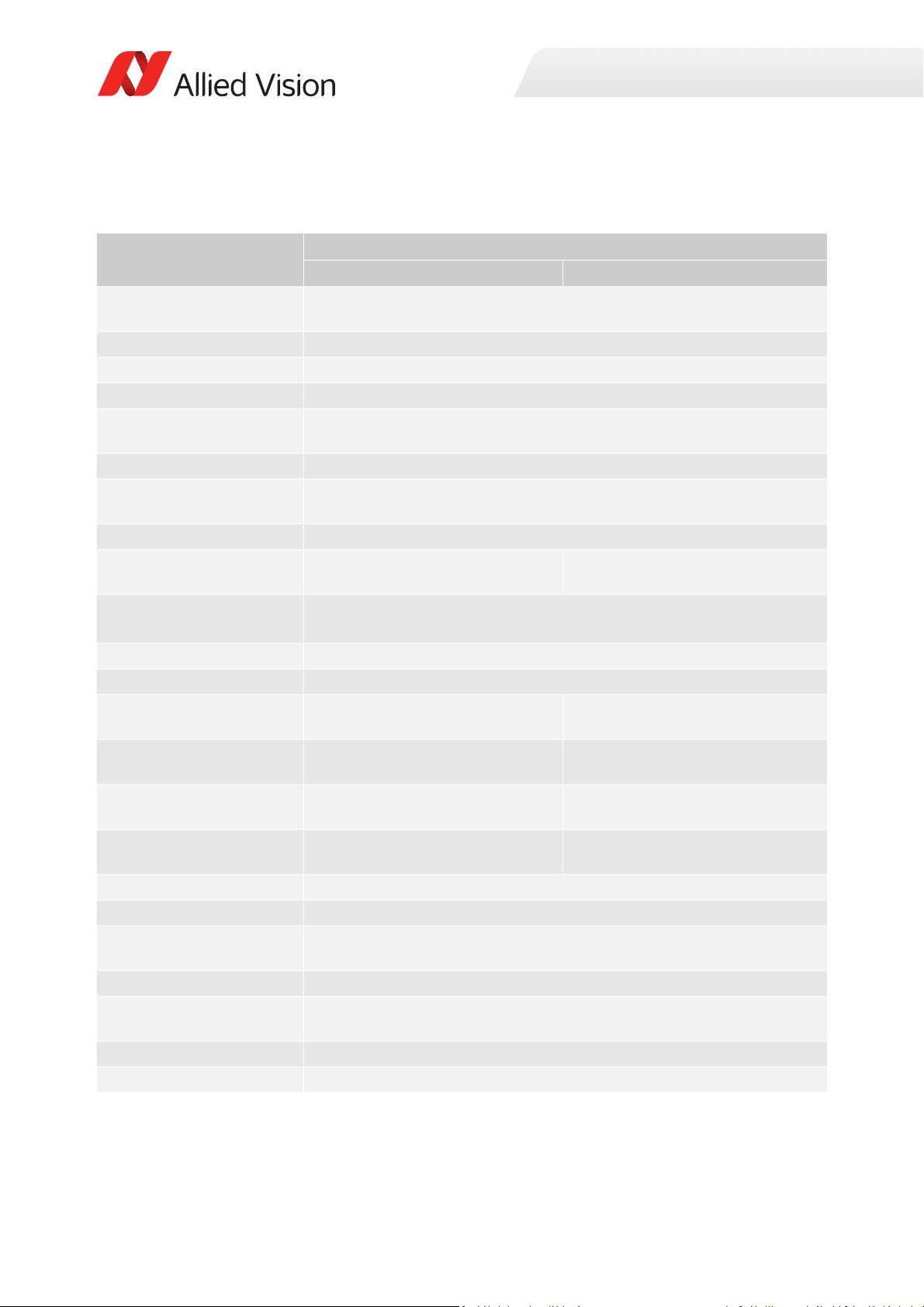
Specifications
Prosilica GT4905, GT4905C
Specification
Feature
Resolution 4896 (H) × 3264 (V)
Sensor ON Semi KAI-16050 TRUESENSE Gen 2
Sensor type Interline CCD, Progressive Scan
Shutter type Global
Sensor size Type APS-H
Pixel size 5.5 μm × 5.5 μm
Lens mount
Housing Large format
Optical filter Standard: No optical filter
Maximum frame rate at full
resolution
Maximum image bit depth 14-bit (monochrome), 12-bit (color)
Image buffer 128 MB
Monochrome formats Mono8, Mono12, Mono12Packed,
Color formats (YUV) N/A YUV411Packed, YUV422Packed,
Color formats (RGB) N/A RGB8Packed, BGR8Packed,
RAW formats N/A BayerGR8, BayerGR12,
Exposure time control 15 µs to 26.8 s, 1 µs increments
Gain control 0 to 32 dB; 1 dB increments
Binning Horizontal: 1 to 8 columns
Decimation Horizontal and vertical: 1, 2, 4, 8 factor
Sensor taps Four-tap
TTL (non-isolated) I/Os 1 input, 2 outputs
Opto-isolated I/Os 1 input, 2 outputs
1
Optional: See the Modular Concept
Mono14
Prosilica GT4905 Prosilica GT4905C
16 MP
32.36 mm diagonal
Standard: F-Mount
Optional: See the Modular Concept
Standard: IRC30 IR cut filter
Optional: See the Modular Concept
Four-tap mode: 7.5 fps (8.5 fps burst mode2)
One-tap mode: 2.2 fps
Mono8
YUV444Packed
RGBA8Packed, BGRA8Packed
BayerRG12Packed
Vertical: 1 to 8 rows
Single-tap switchable in Vimba Viewer 2.0 or later
Table 51: Prosilica GT4905, GT4905C model specifications
94Prosilica GT Technical Manual V2.9.0
Page 95

Specification
Specifications
Feature
Prosilica GT4905 Prosilica GT4905C
RS232 1 TxD, 1 RxD
Voltage requirements 7 to 25 VDC; PoE
Power consumption 7.3 W @ 12 VDC; 9.0 W PoE
Trigger latency 2.5 µs
Trigger jitter ±20 ns
Propagation delay (tpd) 30 ns for non-isolated I/O; 70 ns for isolated I/O
Operating temperature -20 °C to +50 °C ambient temperature (without condensation)
Storage temperature -20 °C to +70 °C ambient temperature (without condensation)
Operating humidity 20 to 80% non-condensing
Body dimensions (L × W × H) 96 × 66 × 53.3 mm
Mass (typical) 372 g
Interface IEEE 802.3 1000BASE-T (Gigabit Ethernet), IEEE 802.3af (PoE)
Interface standard GigE Vision® Standard V1.2
Camera control standard GenICam SFNC V1.2.1
Regulations CE, RoHS, REACH, WEEE, FCC, ICES
Temperature monitoring Available for main board and sensor board
Resolution: 0.031; Accuracy: ±1 °C
1
To enable EF lens control on Prosilica GT cameras you must update firmware to version 01.54.14263 or later. EF lens
control is only supported for cameras with EF lens mount (order option -18).
2
GigE host controller card with jumbo packets is required. See the Hardware Selection for Allied Vision GigE Cameras
application note for a list of recommended GigE host controller cards.
Table 51: Prosilica GT4905, GT4905C model specifications (continued)
95Prosilica GT Technical Manual V2.9.0
Page 96
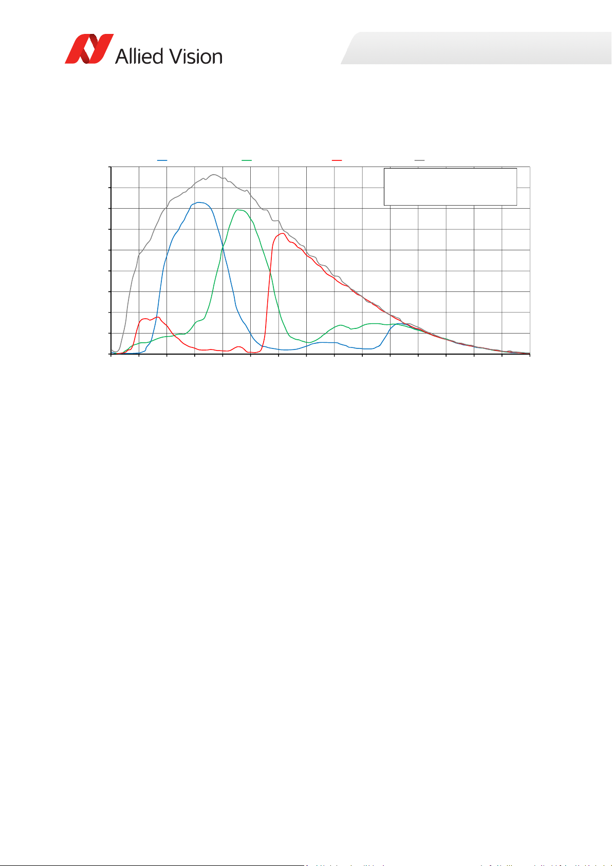
Absolute QE
0%
5%
10%
15%
20%
25%
30%
35%
40%
45%
300 350 400 450 500 550 600 650 700 750 800 850 900 950 1000 1050
QuantumEfficiency
Wavelength[nm]
ONSemiconductorKAIͲ16050absoluteQE
ONSemiconductorGen2CFAmaterialforcolorsensors
Note:MeasuredwithARcoatedcoverglass.
TheuncertaintyofmeasurementoftheQEis+/Ͳ 10.25%.
Thevaluesaretypicalandaresubjecttominorvariations.
BlueQE GreenQE RedQE MonochromeQE
Specifications
Figure 46: Prosilica GT4905, GT4905C (ON Semi KAI-16050 Gen 2) absolute QE
96Prosilica GT Technical Manual V2.9.0
Page 97
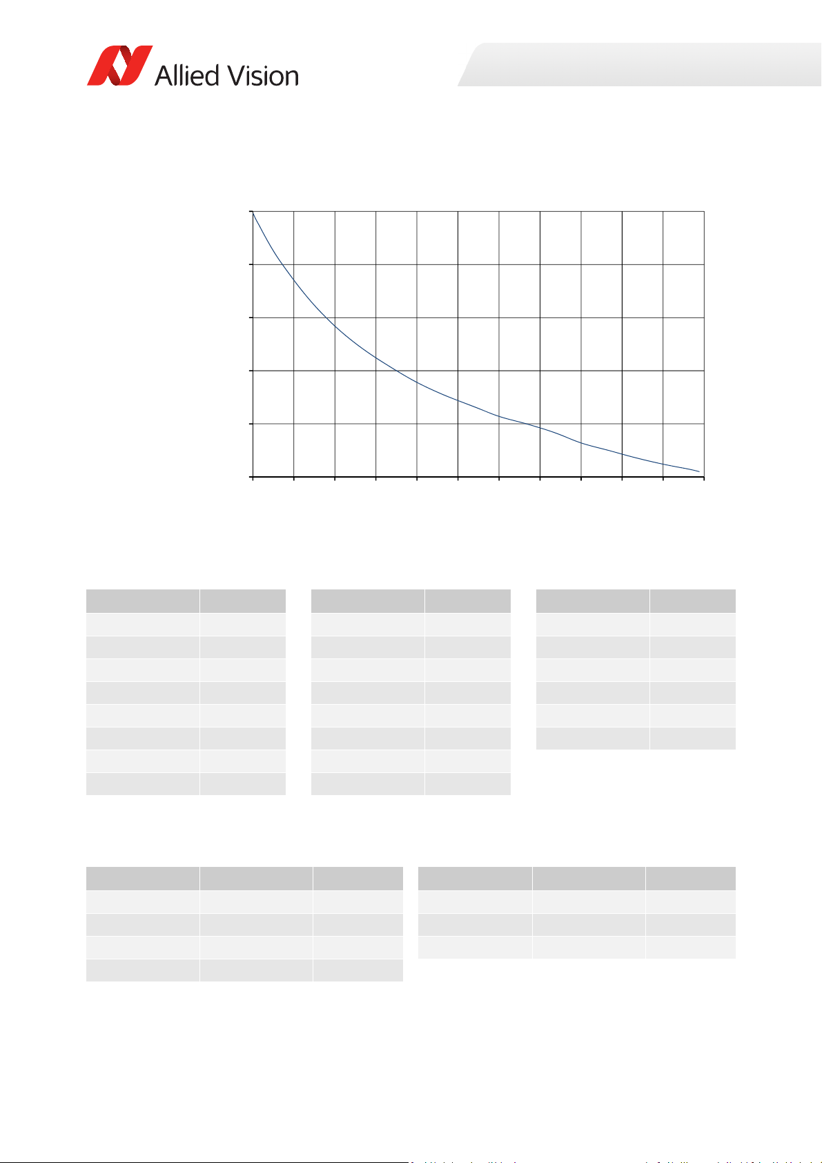
ROI frame rate
7
12
17
22
27
32
0 300 600 900 1200 1500 1800 2100 2400 2700 3000 3300
Framerate[fps]
ROIheight[pixels]
Specifications
Figure 47: Frame rate as a function of ROI height [width=4896 pixels]
Height in pixels Frame rate Height in pixels Frame rate Height in pixels Frame rate
3264 7.5 1800 12.7 200 27.3
3200 7.7 1600 13.7 100 29.4
3000 8.2 1400 14.7 50 30.6
2800 8.8 1200 15.9 20 31.3
2600 9.5 1000 17.4 10 31.6
2400 10.2 800 19.1 2 31.8
2200 11.2 600 21.2
2000 12 400 23.9
Table 52: Frame rate as a function of ROI height [width=4896 pixels]
The following table shows how binning affects frame rate.
BinningVertical Height in pixels Frame rate BinningVertical Height in pixels Frame rate
2 1632 15.1 6 544 31.8
3 1088 20.7 7 466 34.4
4 816 25.1 8 408 36.6
5 652 28.8
Table 53: Frame rate as a function of ROI height with vertical binning enabled
97Prosilica GT Technical Manual V2.9.0
Page 98
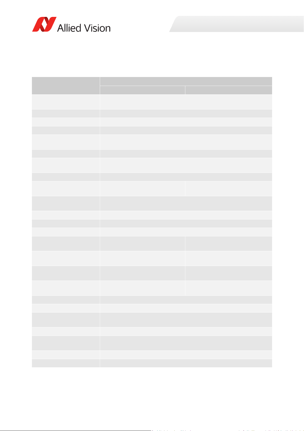
Specifications
Prosilica GT4907, GT4907C
Specification
Feature
Resolution 4864 (H) × 3232 (V)
Sensor ON Semi KAI-16070 TRUESENSE Gen 2
Sensor type Interline CCD, Progressive Scan
Shutter type Global
Sensor size Type 3 5 mm
Pixel size 7.4 μm × 7.4 μm
Lens mount
Housing Large format
Optical filter Standard: No optical filter
Maximum frame rate at full
resolution
Maximum image bit depth 14-bit (monochrome), 12-bit (color)
Image buffer 128 MB
StreamHoldCapacity Up to 8 frames at full resolution
Monochrome formats Mono8, Mono12, Mono12Packed,
Color formats (YUV) N/A YUV411Packed, YUV422Packed,
Color formats (RGB) N/A RGB8Packed, BGR8Packed,
RAW formats N/A BayerGR8, BayerGR12,
Exposure time control 35 µs to 26.8 s, 1 µs increments
Gain control 0 to 35 dB; 1 dB increments
Binning Horizontal: 1 to 8 columns
Decimation X/Y Horizontal and vertical: 1, 2, 4, 8 factor
Sensor taps Four-tap
TTL (non-isolated) I/Os 1 input, 2 outputs
Opto-isolated I/Os 1 input, 2 outputs
1
Optional: See the Modular Concept
Mono14
Prosilica GT4907 Prosilica GT4907C
15.7 MP
43.2 mm diagonal
Standard: F-Mount
Optional: See the Modular Concept
Standard: IRC30 IR cut filter
Optional: See the Modular Concept
Four-tap mode: 7.6 fps
One-tap mode: 2.2 fps
Mono8
YUV444Packed
RGBA8Packed, BGRA8Packed
BayerRG12Packed
Vertical: 1 to 8 rows
Single-tap switchable in Vimba Viewer 2.0 or later
Table 54: Prosilica GT4907, GT4907C model specifications
98Prosilica GT Technical Manual V2.9.0
Page 99

Specification
Specifications
Feature
Prosilica GT4907 Prosilica GT4907C
RS232 1 TxD, 1 RxD
Voltage requirements 7 to 25 VDC; PoE
Power consumption 7.7 W @ 12 VDC; 9.5 W PoE
Trigger latency 2.5 µs
Trigger jitter ±20 ns
Propagation delay (tpd) 30 ns for non-isolated I/O; 70 ns for isolated I/O
Operating temperature -20 °C to +50 °C ambient temperature (without condensation)
Storage temperature -20 °C to +70 °C ambient temperature (without condensation)
Operating humidity 20 to 80% non-condensing
Body dimensions (L × W × H) 96 × 66 × 53.3 mm
Mass (typical) 372 g
Interface IEEE 802.3 1000BASE-T (Gigabit Ethernet), IEEE 802.3af (PoE)
Interface standard GigE Vision® Standard V1.2
Camera control standard GenICam SFNC V1.2.1
Regulations CE, RoHS, REACH, WEEE, FCC, ICES
Temperature monitoring Available for main board and sensor board.
Resolution: 0.031; Accuracy: ±1 °C
1
To enable EF lens control on Prosilica GT cameras you must update firmware to version 01.54.14263 or later. EF lens
control is only supported for cameras with EF lens mount (order option -18).
Table 54: Prosilica GT4907, GT4907C model specifications (continued)
99Prosilica GT Technical Manual V2.9.0
Page 100
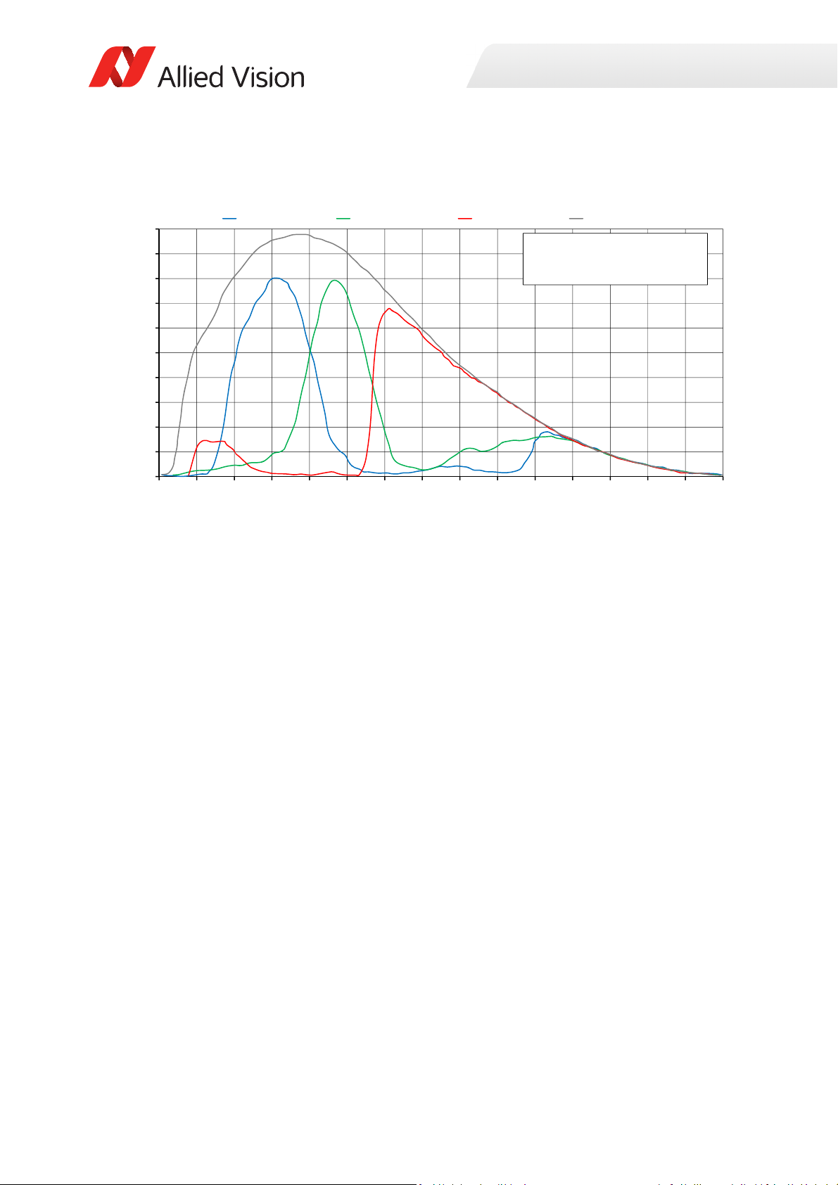
Absolute QE
0%
5%
10%
15%
20%
25%
30%
35%
40%
45%
50%
300 350 400 450 500 550 600 650 700 750 800 850 900 950 1000 1050
QuantumEfficiency
Wavelength[nm]
ONSemiconductorKAIͲ16070absoluteQE
ONSemiconductorGen2CFAmaterialforcolorsensors
Note:MeasuredwithARcoatedcoverglass.
TheuncertaintyofmeasurementoftheQEis+/Ͳ 10.25%.
Thevaluesaretypicalandaresubjecttominorvariations.
BlueQE GreenQE RedQE MonochromeQE
Specifications
Figure 48: Prosilica GT4907, GT4907C (ON Semi KAI-16070 Gen 2) absolute QE
100Prosilica GT Technical Manual V2.9.0
 Loading...