

Page 1
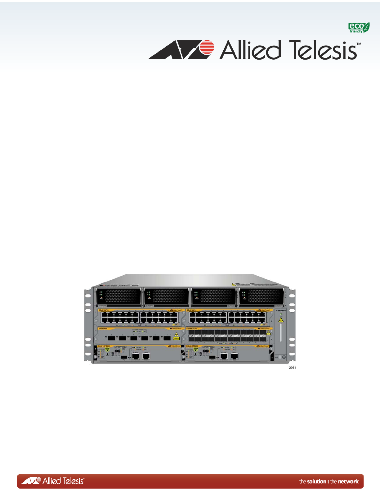
SwitchBlade x8106
Layer 3+ Chassis Switch
AT-SBx8106 Chassis
AT-SBx81GT24 Line Card
AT-SBx81GT40 Line Card
AT-SBx81GP24 PoE Line Card
AT-SBx81GS24a SFP Line Card
AT-SBx81XS6 SFP+ Line Card
AT-SBx81CFC400 Controller Fabric Card
AT-SBxPWRSYS1 AC System Power Supply
AT-SBxPWRSYS1 DC System Power Supply
AT-SBxPWRPOE1 PoE Power Supply
AT-SB xFAN0 6 M od ul e
Installation Guide
613-001835 Rev. A
Page 2

Copyright 2013 Allied Telesis, Inc.
All rights reserved. No part of this publication may be reproduced without prior written permission from Allied Telesis,
Inc.
Allied Telesis, AlliedWare Plus, and the Allied Telesis logo are trademarks of Allied Telesis, Incorporated. All other
product names, company names, logos or other designations mentioned herein are trademarks or registered trademarks of
their respective owners.
Allied Telesis, Inc. reserves the right to make changes in specifications and other information contained in this document
without prior written notice. The information provided herein is subject to change without notice. In no event shall Allied
Telesis, Inc. be liable for any incidental, special, indirect, or consequential damages whatsoever, including but not limited
to lost profits, arising out of or related to this manual or the information contained herein, even if Allied Telesis, Inc. has
been advised of, known, or should have known, the possibility of such damages.
Page 3

Electrical Safety and Emissions Standards
This product meets the following standards.
U.S. Federal Communications Commission
Radiated Energy
Note: This equipment has been tested and found to comply with the limits for a Class A digital device pursuant to Part 15
of FCC Rules. These limits are designed to provide reasonable protection against harmful interference when the
equipment is operated in a commercial environment. This equipment generates, uses, and can radiate radio frequency
energy and, if not installed and used in accordance with this instruction manual, may cause harmful interference to radio
communications. Operation of this equipment in a residential area is likely to cause harmful interference in which case
the user will be required to correct the interference at his own expense.
Note: Modifications or changes not expressly approved of by the manufacturer or the FCC, can void your right to operate
this equipment.
Industry Canada
This Class A digital apparatus complies with Canadian ICES-003.
Cet appareil numérique de la classe A est conforme à la norme NMB-003 du Canada.
European Union Restriction of the Use of Certain Hazardous Substances
(RoHS) in Electrical and Electronic Equipment
This Allied Telesis RoHS-compliant product conforms to the European Union Restriction of the Use of Certain Hazardous
Substances (RoHS) in Electrical and Electronic Equipment. Allied Telesis ensures RoHS conformance by requiring
supplier Declarations of Conformity, monitoring incoming materials, and maintaining manufacturing process controls.
EMI/RFI Emissions: FCC Class A, EN55022 Class A, EN61000-3-2, EN61000-3-3, CISPR Class A,
VCCI Class A, AS/NZS Class A
Warning: In a domestic environment this product may cause radio interference in
which case the user may be required to take adequate measures.
Immunity: EN55024
Electrical Safety: EN60950-1 (TUV), UL 60950-1 (
Safety Agency Approvals:
CULUS
, TUV, C-TICK, CE
CULUS
), EN60825
Laser Safety EN60825
3
Page 4

SwitchBlade x8106 Chassis Switch Installation Guide
Translated Safety Statements
Important: The indicates that a translation of the safety statement is available in a PDF
document titled “Translated Safety Statements” on our web site at
http://www.alliedtelesis.com/support.
4
Page 5

Contents
Preface ............................................................................................................................................................15
Safety Symbols Used in this Document ...........................................................................................................16
Contacting Allied Telesis ..................................................................................................................................17
Chapter 1: Overview ......................................................................................................................................19
Introduction....................................................................................................................................................... 20
AT-SBx8106 Chassis .......................................................................................................................................23
Ethernet Line and Controller Cards Slots................................................................................................... 24
Power Supply Slots .................................................................................................................................... 25
AT-SBx81GT24 Line Card................................................................................................................................ 27
AT-SBx81GT40 Line Card................................................................................................................................ 28
AT-SBx81GP24 PoE Line Card........................................................................................................................29
AT-SBx81GS24a SFP Line Card ..................................................................................................................... 30
AT-SBx81XS6 SFP+ Line Card........................................................................................................................ 31
10/100/1000Base-T Twisted Pair Ports............................................................................................................ 32
Connector Type..........................................................................................................................................32
Speed.........................................................................................................................................................32
Duplex Mode .............................................................................................................................................. 32
Maximum Distance.....................................................................................................................................33
Cable Requirements ..................................................................................................................................33
Automatic MDIX Detection .........................................................................................................................34
Port Pinouts................................................................................................................................................34
Power over Ethernet on the AT-SBx81GP24 Line Card...................................................................................35
Powered Device Classes ........................................................................................................................... 35
Power Budgeting........................................................................................................................................ 36
PoE Wiring ................................................................................................................................................. 36
Port LEDs on the Ethernet Line Cards .............................................................................................................38
AT-SBx81GT24 Line Card .........................................................................................................................38
AT-SBx81GT40 Line Card .........................................................................................................................39
AT-SBx81GP24 Line Card ......................................................................................................................... 41
AT-SBx81GS24a Line Card .......................................................................................................................42
AT-SBx81XS6 Line Card ...........................................................................................................................43
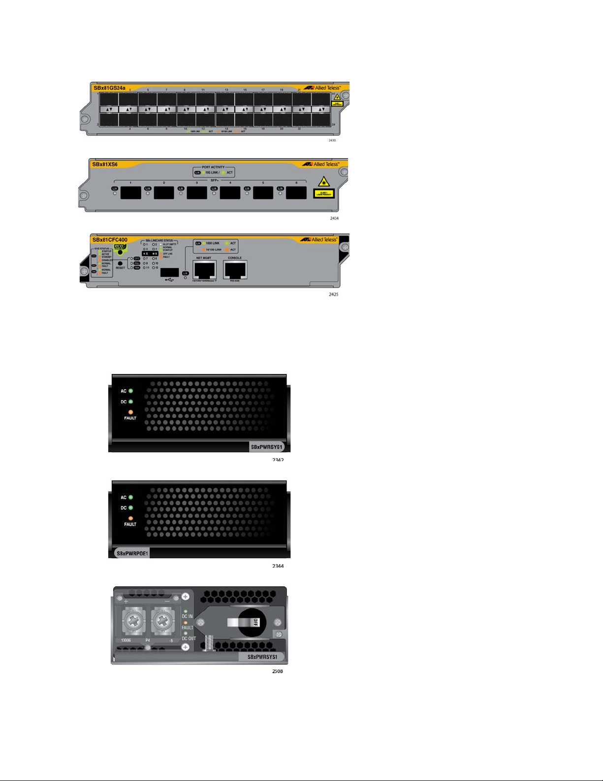
AT-SBx81CFC400 Controller Fabric Card .......................................................................................................44
SYS Status LEDs ....................................................................................................................................... 45
SBx STATUS LEDs....................................................................................................................................47
eco-friendly Button ..................................................................................................................................... 48
Reset Button .............................................................................................................................................. 48
NET MGMT Port ........................................................................................................................................49
NET MGMT LED ........................................................................................................................................ 51
Console (RS-232) Port............................................................................................................................... 51
USB Port .................................................................................................................................................... 52
AT-SBxPWRSYS1 AC Power Supply ..............................................................................................................53
LEDs ..........................................................................................................................................................53
AT-SBxPWRPOE1 Power Supply ....................................................................................................................55
LEDs ..........................................................................................................................................................55
5
Page 6

Contents
AT-SBxPWRSYS1 DC Power Supply.............................................................................................................. 57
LEDs.......................................................................................................................................................... 58
AT-SBxFAN06 Module..................................................................................................................................... 59
LED............................................................................................................................................................ 59
Power Supply Interfaces (Opto-couplers) ........................................................................................................ 60
LED............................................................................................................................................................ 60
AlliedWare Plus Software Releases for the Hardware Components ............................................................... 62
Chapter 2: Safety Precautions and Site Requirements ............................................................................. 63
Reviewing Safety Precautions ......................................................................................................................... 64
Selecting a Site for the SwitchBlade x8106 ..................................................................................................... 68
Installation Tools and Material ......................................................................................................................... 70
Chapter 3: Installing the Chassis in an Equipment Rack .......................................................................... 71
Required Tools and Material............................................................................................................................ 72
Preparing the Equipment Rack ........................................................................................................................ 73
Unpacking the AT-SBx8106 Chassis ............................................................................................................... 76
Removing the Rubber Feet .............................................................................................................................. 78
Adjusting the Equipment Rack Brackets .......................................................................................................... 80
Installing the Chassis in the Equipment Rack .................................................................................................. 82
Removing the Shipping Brace ......................................................................................................................... 86
Installing the Chassis Grounding Lug .............................................................................................................. 87
Chapter 4: Installing the Power Supplies ................................................................................................... 89
Protecting Against Electrostatic Discharge (ESD) ........................................................................................... 90
Installing the AT-SBxPWRSYS1 AC System Power Supply............................................................................ 91
Installing the AT-SBxPWRPOE1 PoE Power Supply....................................................................................... 97
Installing the AT-SBxPWRSYS1 DC Power Supply....................................................................................... 103
Chapter 5: Installing the AT-SBx81CFC400 Controller and Ethernet Line Cards ................................. 109
Guidelines to Handling the Controller and Line Cards ................................................................................... 110
Installing the AT-SBx81CFC400 Controller Fabric Card................................................................................ 112
Installing the Ethernet Line Cards .................................................................................................................. 118
Installing the Blank Slot Covers ..................................................................................................................... 122
Chapter 6: Installing the Transceivers and Cabling the Ports ................................................................ 125
Cabling Guidelines for the Twisted Pair Ports on the AT-SBx81GT24, AT-SBx81GP24, and
AT-SBx81GT40 Line Cards ........................................................................................................................... 126
Connecting Cables to the AT-SBx81GT40 Line Card ............................................................................. 127
Guidelines to Installing SFP and SFP+ Transceivers .................................................................................... 129
Installing SFP Transceivers in the AT-SBx81GS24a Line Card .................................................................... 130
Installing SFP+ Transceivers in the AT-SBx81XS6 Line Card.......................................................................134
Installing AT-SP10TW Cables in the AT-SBx81XS6 Line Card ..................................................................... 138
Cabling the NET MGMT Port on the AT-SBx81CFC400 Card....................................................................... 141
Chapter 7: Powering On the Chassis ........................................................................................................ 143
Verifying the Installation................................................................................................................................. 144
Powering On the AT-SBxPWRSYS1 AC Power Supply ................................................................................ 145
Powering On the AT-SBxPWRPOE1 Power Supply......................................................................................148
Powering On the AT-SBxPWRSYS1 DC System Power Supply ................................................................... 151
Choosing a Method for Attaching the Grounding Wire ............................................................................ 153
Connecting the Grounding Wire with the Grounding Terminal ................................................................ 153
Connecting the Grounding Wire with Bare Wire...................................................................................... 156
Choosing a Method for Attaching the Power Wires.................................................................................158
Connecting the DC Power Wires with the Straight Terminals ................................................................. 158
Connecting the DC Power Wires with the Right Angle Terminals ........................................................... 167
Connecting Bare DC Power Wires .......................................................................................................... 173
6
Page 7

SwitchBlade x8106 Chassis Switch Installation Guide
Monitoring the Initialization Process ...............................................................................................................177
Using the LEDs to Monitor the Initialization Process ............................................................................... 177
Using the Console Port to Monitor the Initialization Process ...................................................................177
Chapter 8: Verifying the Hardware Operations of the Chassis ...............................................................181
Using the LEDs to Verify the Chassis.............................................................................................................182
Using Local Management to Verify the Chassis.............................................................................................184
Starting a Local Management Session .................................................................................................... 184
Entering the AlliedWare Plus Operating System Commands ..................................................................185
Chapter 9: Troubleshooting .......................................................................................................................189
AT-SBxPWRSYS1 and AT-SBxPWRPOE1 AC Power Supplies ................................................................... 190
AT-SBxPWRSYS1 DC Power Supply ............................................................................................................ 191
Ethernet Line Cards........................................................................................................................................193
Twisted Pair Ports .......................................................................................................................................... 195
Power Over Ethernet ......................................................................................................................................197
Fiber Optic Transceivers ................................................................................................................................ 199
AT-SBx81CFC400 Controller Fabric Card .....................................................................................................200
AT-SBxFAN06 Fan Module ............................................................................................................................201
Local (Out-of-Band) Management Session ....................................................................................................202
Power Supply Interfaces (Opto-couplers).......................................................................................................203
Chapter 10: Replacing Modules .................................................................................................................205
Replacing AT-SBxPWRSYS1 AC and AT-SBxPWRPOE1 Power Supplies ..................................................206
Replacing the AT-SBxPWRSYS1 DC Power Supply .....................................................................................211
Replacing Ethernet Line Cards.......................................................................................................................222
Replacing the AT-SBx81CFC400 Controller Fabric Card .............................................................................. 224
Replacing the AT-SBxFAN06 Fan Module .....................................................................................................226
Removing the AT-SBxFAN06 Fan Module ..............................................................................................226
Installing a New AT-SBxFAN06 Fan Module ...........................................................................................229
Appendix A: Technical Specifications ......................................................................................................233
Physical Specifications ................................................................................................................................... 233
Environmental Specifications .........................................................................................................................235
Power Specifications ...................................................................................................................................... 236
Safety and Electromagnetic Emissions Certifications ....................................................................................238
Port Pinouts ....................................................................................................................................................239
7
Page 8

Contents
8
Page 9

Figures
Figure 1: AT-SBx8106 Chassis ........................................................................................................................................... 20
Figure 2: Ethernet Line Cards and Controller Card ............................................................................................................. 20
Figure 3: Ethernet Line Cards and Controller Card (Continued) ......................................................................................... 21
Figure 4: Power Supply Units .............................................................................................................................................. 21
Figure 5: Fan Module .......................................................................................................................................................... 22
Figure 6: Front View of the AT-SBx8106 Chassis ............................................................................................................... 23
Figure 7: Rear View of the AT-SBx8106 Chassis................................................................................................................ 24
Figure 8: AT-SBx8106 Chassis with Line Cards, Controller Cards, and Power Supplies ................................................... 24
Figure 9: Ethernet Line and Controller Cards Slots ............................................................................................................. 25
Figure 10: Power Supply Slots ............................................................................................................................................ 25
Figure 11: AT-SBx81GT24 Line Card.................................................................................................................................. 27
Figure 12: AT-SBx81GT40 Line Card.................................................................................................................................. 28
Figure 13: AT-SBx81GP24 PoE Line Card.......................................................................................................................... 29
Figure 14: AT-SBx81GS24a SFP Line Card ....................................................................................................................... 30
Figure 15: AT-SBx81XS6 Line Card.................................................................................................................................... 31
Figure 16: Port LEDs on the AT-SBx81GT24 Line Card ..................................................................................................... 38
Figure 17: Port LEDs on an RJ Point 5 Cable Connector for the AT-SBx81GT40 Line Card ............................................. 39
Figure 18: Port LEDs on an RJ Point 5 Cable Connector for the AT-SBx81GT40 Line Card ............................................. 40
Figure 19: Port LEDs on the AT-SBx81GP24 PoE Line Card ............................................................................................. 41
Figure 20: Port LEDs on the AT-SBx81GS24a SFP Line Card ........................................................................................... 42
Figure 21: SFP+ Slot LEDs on the AT-SBx81XS6 Line Card.............................................................................................. 43
Figure 22: AT-SBx81CFC400 Controller Fabric Card ......................................................................................................... 45
Figure 23: AT-SBxPWRSYS1 AC Power Supply .......................................................................................
Figure 24: AT-SBxPWRPOE1 Power Supply...................................................................................................................... 55
Figure 25: AT-SBxPWRSYS1 DC Power Supply ................................................................................................................ 57
Figure 26: AT-SBxFAN06 Module ....................................................................................................................................... 59
Figure 27: Power Supply Interfaces (Opto-couplers)........................................................................................................... 60
Figure 28: 100 - 125 VAC 125 V NEMA 5-20 Plug and Receptacle.................................................................................... 69
Figure 29: Reserving Vertical Rack Space.......................................................................................................................... 74
Figure 30: Rack Mounting Hole Locations........................................................................................................................... 75
Figure 31: Components of the AT-SBx8106 Chassis .......................................................................................................... 76
Figure 32: Components of the AT-SBx8106 Chassis (Continued) ...................................................................................... 77
Figure 33: Turning the Chassis Upside Down ..................................................................................................................... 78
Figure 34: Removing the Rubber Feet ................................................................................................................................ 79
Figure 35: Rack Mounting Bracket Locations...................................................................................................................... 81
Figure 36: Rack Bracket Locations for Reverse Position of Chassis................................................................................... 81
Figure 37: Lifting the AT-SBx8106 Chassis into the Equipment Rack................................................................................. 83
Figure 38: Installing the Rack Mount Screws ...................................................................................................................... 84
Figure 39: Tightening the Rack Mount Screws.................................................................................................................... 85
Figure 40: Removing the Shipping Brace............................................................................................................................ 86
Figure 41: Stripping the Grounding Wire ............................................................................................................................. 87
Figure 42: Removing the Grounding Lug............................................................................................................................. 87
Figure 43: Attaching the Grounding Wire to the Grounding Lug.......................................................................................... 88
Figure 44: Installing the Grounding Lug and Wire ............................................................................................................... 88
Figure 45: ESD Socket and Wrist Strap .............................................................................................................................. 90
Figure 46: Power Supply Slots ............................................................................................................................................ 91
Figure 47: Removing the Blank Slot Cover from Power Supply Slot C ............................................................................... 92
Figure 48: Items Included with the AT-SBxPWRSYS1 Power Supply Module...........................................................
Figure 49: Verifying the AT-SBxPWRSYS1 Power Supply ................................................................................................. 94
......................... 53
......... 93
9
Page 10

List of Figures
Figure 50: Unlocking the Handle on the AT-SBxPWRSYS1 Power Supply ........................................................................ 94
Figure 51: Inserting the AT-SBxPWRSYS1 Power Supply.................................................................................................. 95
Figure 52: Lowering the Handle on the AT-SBxPWRSYS1 Power Supply.......................................................................... 96
Figure 53: Removing the Blank Slot Cover from Power Supply Slot A................................................................................ 98
Figure 54: Items Included with the AT-SBxPWRPOE1 Power Supply Module.................................................................... 99
Figure 55: Verifying the AT-SBxPWRPOE1 PoE Power Supply ....................................................................................... 100
Figure 56: Unlocking the Handle on the AT-SBxPWRPOE1 Power Supply ...................................................................... 100
Figure 57: Inserting the AT-SBxPWRPOE1 Power Supply ............................................................................................... 101
Figure 58: Locking the Handle on the AT-SBxPWRPOE1 Power Supply ......................................................................... 102
Figure 59: Removing the Blank Slot Cover from Power Supply Slot C.............................................................................. 104
Figure 60: Items Included with the AT-SBxPWRSYS1 DC Power Supply Module............................................................ 105
Figure 61: Loosening the Handle locking Screw on the AT-SBxPWRPOE1 DC Power Supply ........................................ 106
Figure 62: Raising the Handle on the AT-SBxPWRPOE1 DC Power Supply.................................................................... 106
Figure 63: Inserting the AT-SBxPWRSYS1 DC Power Supply.......................................................................................... 107
Figure 64: Locking the Handle on the AT-SBxPWRSYS1 Power Supply.......................................................................... 108
Figure 65: Aligning Card in Slot ......................................................................................................................................... 111
Figure 66: Slots 5 and 6 for the AT-SBx81CFC400 Card .................................................................................................. 112
Figure 67: Items Included with the AT-SBx81CFC400 Controller Fabric Card.................................................................. 113
Figure 68: Removing the AT-SBx81CFC400 Controller Fabric Card from the Anti-static Bag .......................................... 113
Figure 69: Opening the Locking Handles on the AT-SBx81CFC400 Controller Fabric Card ............................................ 114
Figure 70: Removing the Battery Insulator ........................................................................................................................ 114
Figure 71: Aligning the AT-SBx81CFC400 Card in the Chassis Slot................................................................
Figure 72: Closing the Locking Levers on the AT-SBx81CFC400 Controller Fabric Card ................................................ 116
Figure 73: Tightening the Thumb Screws on the AT-SBx81CFC400 Card ....................................................................... 117
Figure 74: Removing an Ethernet Line Card from the Anti-static Bag............................................................................... 119
Figure 75: Aligning an Ethernet Line Card in a Chassis Slot ............................................................................................. 119
Figure 76: Seating an Ethernet Line Card on the Backplane Connector ........................................................................... 120
Figure 77: Tightening the Thumb Screws on an Ethernet Line Card................................................................................. 121
Figure 78: Installing a Blank Slot Cover............................................................................................................................. 122
Figure 79: Tightening the Thumbscrews on a Blank Slot Cover........................................................................................ 123
Figure 80: RJ Point 5 Cable Connector for AT-SBx81GT40 Line Card ............................................................................. 127
Figure 81: Connecting Cables to Ports on the AT-SBx81GT40 Line Card ........................................................................ 128
Figure 82: Removing the Dust Cover from an SFP Slot in the AT-SBx81GS24a Line Card ............................................. 130
Figure 83: Handle on SFP Transceiver.............................................................................................................................. 131
Figure 84: Inserting the SFP Transceiver in the AT-SBx81GS24a Line Card ................................................................... 131
Figure 85: Removing the Dust Cover from the SFP Transceiver in the AT-SBx81GS24a Line Card................................ 132
Figure 86: Verifying the Position of the Handle on the SFP Transceiver on the AT-SBx81GS24a Line Card................... 132
Figure 87: Attaching a Fiber Optic Cable to an SFP Transceiver in the AT-SBx81GS24a Line Card ............................... 133
Figure 88: Removing the Dust Cover from an SFP+ Slot in the AT-SBx81XS6 Line Card ............................................... 134
Figure 89: Handle on SFP+ Transceiver ........................................................................................................................... 135
Figure 90: Installing an SFP+ Transceiver in the AT-SBx81XS6 Line Card ...................................................................... 135
Figure 91: Removing the Dust Cover from an SFP+ Transceiver in the AT-SBx81XS6 Line Card................................... 136
Figure 92: Verifying the Position of the Handle on the SFP+ Transceiver on the AT-SBx81XS6 Line Card..................... 136
Figure 93: Attaching a Fiber Optic Cable to an SFP+ Transceiver in the AT-SBx81XS6 Line Card ................................. 137
Figure 94: Removing the Dust Cover From an SFP+ Slot in the AT-SBx81XS6 Line Card .............................................. 138
Figure 95: Release Tab on the AT-SBx81XS6 Line Card.................................................................................................. 139
Figure 96: Installing the AT-SP10TW Cable in the AT-SBx81XS6 Line Card ................................................................... 139
Figure 97: AC Sockets on the Rear Panel of the AT-SBx8106 Chassis............................................................................ 145
Figure 98: Connecting the AC Power Cord for the AT-SBxPWRSYS1 AC Power Supply ................................................ 1
Figure 99: Securing the Power Cord for the AT-SBxPWRSYS1 AC Power Supply to an Anchor..................................... 147
Figure 100: Connecting the AC Power Cord for the AT-SBxPWRPOE1 Power Supply.................................................... 148
Figure 101: Securing the Power Cord for the AT-SBxPWRPOE1 Power Supply to an Anchor ........................................ 149
Figure 102: Dress and Secure AC Power Cords ............................................................................................................... 150
Figure 103: Components of the AT-SBxPWRSYS1 DC Power Supply ............................................................................. 152
Figure 104: Grounding Wire Terminal................................................................................................................................ 153
Figure 105: Stripping the Stranded Grounding Wire.......................................................................................................... 153
Figure 106: Attaching the Stranded Grounding Wire to the Grounding Terminal .............................................................. 153
Figure 107: Removing the Nut and Washer from the Grounding Post .............................................................................. 154
Figure 108: Installing the Grounding Wire ......................................................................................................................... 155
Figure 109: Stripping the solid or Stranded Grounding Wire ............................................................................................. 156
................. 115
46
10
Page 11

SwitchBlade x8106 Chassis Switch Installation Guide
Figure 110: Attaching the Bare Grounding Wire to the Grounding Post............................................................................ 156
Figure 111: Securing the Bare Grounding Wire to the Grounding Post............................................................................. 157
Figure 112: Power Wire Terminals .................................................................................................................................... 158
Figure 113: Stripping the Power Wires.............................................................................................................................. 159
Figure 114: Attaching the Power Wires to the Straight Terminal Lugs .............................................................................. 159
Figure 115: On/Off Switch on the AT-SBxPWRSYS1 DC Power Supply.......................................................................... 160
Figure 116: Opening the Plastic Cover.............................................................................................................................. 161
Figure 117: Removing the Terminal Screws...................................................................................................................... 162
Figure 118: Connecting the Positive (+) Power Wire with a Straight Terminal.................................................................. 163
Figure 119: Connecting the Negative (-) Power Wire with a Straight Terminal ................................................................. 164
Figure 120: Closing the Plastic Cover over the Terminal Connectors ............................................................................... 165
Figure 121: Tightening the Handle Locking Screw ............................................................................................................ 166
Figure 122: Stripping the Power Wires.............................................................................................................................. 167
Figure 123: Attaching the Power Wires to the Right Angle Terminals............................................................................... 167
Figure 124: Removing the Plastic Cover ........................................................................................................................... 168
Figure 125: Removing the Terminal Screws...................................................................................................................... 169
Figure 126: Connecting the Positive (+) Power Wire with a Right Angle Terminal............................................................ 170
Figure 127: Connecting the Negative (-) Power Wire with a Right Angle Terminal ........................................................... 171
Figure 128: Tightening the Handle Locking Screw ............................................................................................................ 172
Figure 129: Stripping Solid or Stranded DC Power Wires................................................................................................. 173
Figure 130: Connecting the Positive Lead Wire ................................................................................................................ 174
Figure 131: Connecting the Negative Lead Wire............................................................................................................... 175
Figure 132: Switch Initialization Messages........................................................................................................................ 178
Figure 133: Switch Initialization Messages (Continued) .................................................................................................... 179
Figure 134: Connecting the Management Cable to the Console RS-232 Port .........................................................
Figure 135: SHOW VERSION Command.......................................................................................................................... 186
Figure 136: SHOW CARD Command................................................................................................................................ 186
Figure 137: Disconnecting the AC Power Cord from the AC Socket on the Back Panel................................................... 206
Figure 138: Lifting the Locking Handle on the Power Supply ............................................................................................ 207
Figure 139: Removing the Power Supply from the Chassis .............................................................................................. 208
Figure 140: Installing a Blank Power Supply Slot Cover ................................................................................................... 209
Figure 141: Lowering the Locking Handle on the Power Supply Slot Cover ..................................................................... 210
Figure 142: Loosening the Screw on the Locking Handle ................................................................................................. 211
Figure 143: Opening the Plastic Window on the Terminal Block....................................................................................... 212
Figure 144: Removing the Negative Lead Wire................................................................................................................. 213
Figure 145: Removing the Positive Lead Wire from the Terminal Block ........................................................................... 214
Figure 146: Reinstalling the Screws on the Positive and Negative Terminals................................................................... 215
Figure 147: Closing the Plastic Cover ............................................................................................................................... 216
Figure 148: Removing the Grounding Wire ....................................................................................................................... 217
Figure 149: Reinstalling the Nut and Washer on the Grounding Post ............................................................................... 218
Figure 150: Lifting the Locking Handle and Removing the Power Supply ......................................................................... 219
Figure 151: Installing a Blank Power Supply Slot Cover ................................................................................................... 220
Figure 152: Lowering the Locking Handle on the Power Supply Slot Cover ..................................................................... 221
Figure 153: Loosening the Screw on the AT-SBxFAN06 Fan Module .............................................................................. 227
Figure 154: Loosening the AT-SBxFAN06 Fan Module from the Backplane Connector ................................................... 227
Figure 155: Withdrawing the AT-SBxFAN06 Fan Module 25 mm (1 in.) from the Chassis ............................................... 228
Figure 156: Removing the AT-SBxFAN06 Fan Module from the Chassis......................................................................... 229
Figure 157: Installing a New AT-SBxFAN06 Fan Module.................................................................................................. 230
Figure 158: Securing the AT-SBxFAN06 Fan Module on the Backplane Connector .....................................................
Figure 159: Tightening the Screw on the AT-SBxFAN06 Fan Module .............................................................................. 231
Figure 160: Pin Numbers for RJ-45 and RJ Point 5 Ports (Front View) ............................................................................ 239
......... 184
... 231
11
Page 12

List of Figures
12
Page 13

Tab les
Table 1. Twisted Pair Cable for the AT-SBx81GT24 and AT-SBx81GT40 Line Cards ...................................................... 33
Table 2. Twisted Pair Cable for the AT-SBx81GP24 Line Card .........................................................................................34
Table 3. IEEE802.3af and IEEE802.3at Powered Device Classes ....................................................................................35
Table 4. Maximum Number of Powered Devices ...............................................................................................................36
Table 5. Port LEDs on the AT-SBx81GT24 Line Card .......................................................................................................38
Table 6. Port LEDs on the AT-SBx81GT40 Line Card .......................................................................................................40
Table 7. Port LEDs on the AT-SBx81GP24 PoE Line Card ...............................................................................................41
Table 8. Port LEDs on the AT-SBx81GS24a SFP Line Card .............................................................................................42
Table 9. SFP+ Slot LEDs on the AT-SBx81XS6 Line Card ................................................................................................43
Table 10. SYS (System) Status LEDs ................................................................................................................................46
Table 11. SBx LINECARD STATUS LEDs .........................................................................................................................47
Table 12. Features that Use the NET MGMT Port .............................................................................................................50
Table 13. NET MGMT Port LED .........................................................................................................................................51
Table 14. AT-SBxPWRSYS1 Power Supply LEDs .............................................................................................................53
Table 15. AT-SBxPWRPOE1 Power Supply LEDs ............................................................................................................56
Table 16. LEDs on the AT-SBxPWRSYS1 DC Power Supply ............................................................................................58
Table 17. AT-SBxFAN06 Module LED ...............................................................................................................................59
Table 18. Power Supply Interface LED ...............................................................................................................................61
Table 19. AlliedWare Plus Operating System Releases for the Hardware Components ...................................................62
Table 20. Front Panel to Rack Rail Dimensions .................................................................................................................80
Table 21. Product Dimensions ..........................................................................................................................................233
Table 22. Product Weights ...............................................................................................................................................233
Table 23. Environmental Specifications ............................................................................................................................235
Table 24. Acoustic Noise Test Components .....................................................................................................................235
Table 25. AC Voltage and Frequency Requirements .......................................................................................................236
Table 26. DC Voltage Requirements ................................................................................................................................236
Table 27. Typical Power Savings in eco-friendly Mode ....................................................................................................236
Table 28. Maximum Power Consumption ..........................................................................................
Table 29. Maximum Power Efficiency ...............................................................................................................................237
Table 30. Heat Dissipation ...............................................................................................................................................237
Table 31. Available Power Over Ethernet with One PoE Power Supply ..........................................................................237
Table 32. Available Power Over Ethernet with Two PoE Power Supplies ........................................................................ 238
Table 33. PoE Mode on the AT-SBx81GP24 PoE Line Card ...........................................................................................238
Table 34. Safety and Electromagnetic Emissions ............................................................................................................238
Table 35. MDI Pin Signals (10Base-T or 100Base-TX) ....................................................................................................239
Table 36. MDI-X Pin Signals (10Base-T or 100Base-TX) ................................................................................................239
Table 37. 1000Base-T Connector Pinouts ........................................................................................................................240
...............................236
13
Page 14

List of Tables
14
Page 15

Preface
Note
This guide contains the hardware installation instructions for the Layer 3+
SwitchBlade x8106 Chassis Switch. The preface contains the following
sections:
“Safety Symbols Used in this Document” on page 16
“Contacting Allied Telesis” on page 17
This version of the installation guide applies to release 5.4.3 of the
AlliedWare Plus
Chassis Switch.
™ Operating System for the SwitchBlade x8106
15
Page 16
Preface
Note
Caution
Warning
Warning
Warning
Safety Symbols Used in this Document
This document uses the following conventions.
Notes provide additional information.
Cautions inform you that performing or omitting a specific action
may result in equipment damage or loss of data.
Warnings inform you that performing or omitting a specific action
may result in bodily injury.
Laser warnings inform you that an eye or skin hazard exists due to
the presence of a Class 1 laser device.
Fan warnings inform you of danger from hazardous moving fan
blades.
16
Page 17

Contacting Allied Telesis
If you need assistance with this product, you may contact Allied Telesis
technical support by going to the Support & Services section of the Allied
Telesis web site at www.alliedtelesis.com/support. You can find links for
the following services on this page:
24/7 Online Support — Enter our interactive support center to search
for answers to your product questions in our knowledge database, to
check support tickets, to learn about RMAs, and to contact Allied
Telesis technical experts.
USA and EMEA phone support — Select the phone number that best
fits your location and customer type.
Hardware warranty information — Learn about Allied Telesis
warranties and register your product online.
Replacement Services — Submit a Return Merchandise Authorization
(RMA) request via our interactive support center.
SwitchBlade x8106 Chassis Switch Installation Guide
Documentation — View the most recent installation and user guides,
software release notes, white papers, and data sheets for your
products.
Software Downloads — Download the latest software releases for your
managed products.
For sales or corporate information, go to www.alliedtelesis.com/
purchase and select your region.
17
Page 18

Preface
18
Page 19

Chapter 1
Note
Overview
This chapter describes the Layer 3+ SwitchBlade x8106 Chassis Switch in
the following sections:
“Introduction” on page 20
“AT-SBx8106 Chassis” on page 23
“AT-SBx81GT24 Line Card” on page 27
“AT-SBx81GT40 Line Card” on page 28
“AT-SBx81GP24 PoE Line Card” on page 29
“AT-SBx81GS24a SFP Line Card” on page 30
“AT-SBx81XS6 SFP+ Line Card” on page 31
“10/100/1000Base-T Twisted Pair Ports” on page 32
“Power over Ethernet on the AT-SBx81GP24 Line Card” on page 35
“Port LEDs on the Ethernet Line Cards” on page 38
“AT-SBx81CFC400 Controller Fabric Card” on page 44
“AT-SBxPWRSYS1 AC Power Supply” on page 53
“AT-SBxPWRPOE1 Power Supply” on page 55
“AT-SBxPWRSYS1 DC Power Supply” on page 57
“AT-SBxFAN06 Module” on page 59
“Power Supply Interfaces (Opto-couplers)” on page 60
“AlliedWare Plus Software Releases for the Hardware Components” on
page 62
This version of the installation guide applies to release 5.4.3 of the
AlliedWare Plus Operating System for the SwitchBlade x8106
Chassis Switch.
19
Page 20
Chapter 1: Overview
Slots for four Ethernet line
cards, two controller cards, two
system power supplies, and two
PoE+ power supplies.
AT-SBx81GT24 Ethernet Line Card
with 24 10/100/1000Base-T twisted
pair ports.
AT-SBx81GT40 Ethernet Line Card
with 40 10/100/1000Base-T twisted
pair ports, with RJ point 5
connectors.
AT-SBx81GP24 Ethernet Line Card
with 24 10/100/1000Base-T twisted
pair ports, with PoE+.
Introduction
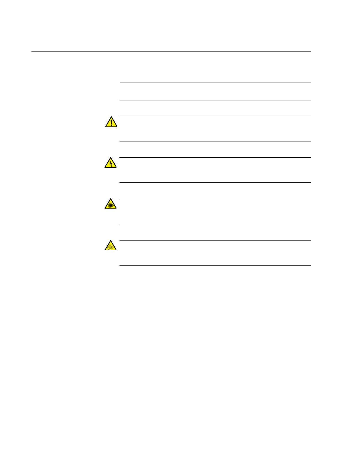
The SwitchBlade x8106 product is a modular Layer 3+ Ethernet switch.
The main components are the AT-SBx8106 Chassis, Ethernet line cards,
a controller card. system power supplies, Power over Ethernet Plus
(PoE+) power supply, and fan module. The AT-SBx8106 Chassis is
shown in Figure 1.
Figure 1. AT-SBx8106 Chassis
The Ethernet line cards and controller card are shown in Figure 2 here and
Figure 3 on page 21.
20
Figure 2. Ethernet Line Cards and Controller Card
Page 21
SwitchBlade x8106 Chassis Switch Installation Guide
AT-SBx81GS24a SFP Ethernet Card
with 24 slots for 100 or 1000Mbps,
fiber optic or twisted pair SFP
transceivers.
AT-SBx81XS6 SFP+ Ethernet Card
with six slots for 10Gbps, fiber optic
SFP+ transceivers, or Twinax direct
connect cables.
AT-SBx81CFC400 Controller Fabric
Card.
AT-SBxPWRSYS1 AC Power Supply for
the Ethernet line cards, controller card,
and fan module.
AT-SBxPWRPOE1 AC Power Supply
with 1200 W PoE budget for the ports on
the AT-SBx81GP24 PoE Ethernet Line
Card.
AT-SBxPWRSYS1 DC Power Supply
for the Ethernet line cards, controller
modules, and fan module.
Figure 3. Ethernet Line Cards and Controller Card (Continued)
Figure 4 illustrates the power supply modules.
Figure 4. Power Supply Units
21
Page 22
Chapter 1: Overview
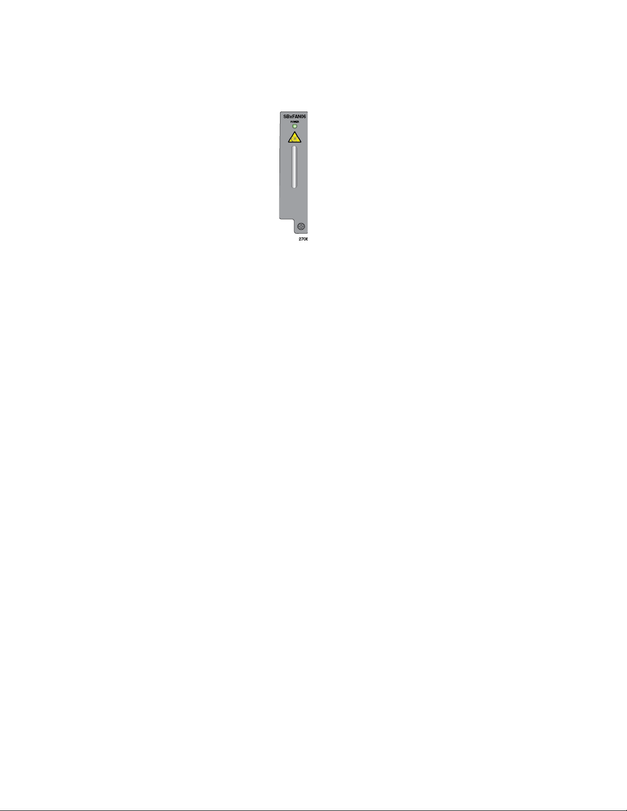
AT-SBxFAN06 Module. The cooling
module for the chassis.
Figure 5 illustrates the fan module.
Figure 5. Fan Module
22
Page 23
AT-SBx8106 Chassis
Note
Shipping Brace
Slots for Ethernet
Line Cards and
Controller Cards
PoE Power
Supply Slots
System Power
Supply Slots
Slots for Ethernet
Line Cards and
Controller Cards
AT-SBxFAN06
Module
ESD Wrist
Strap Plug
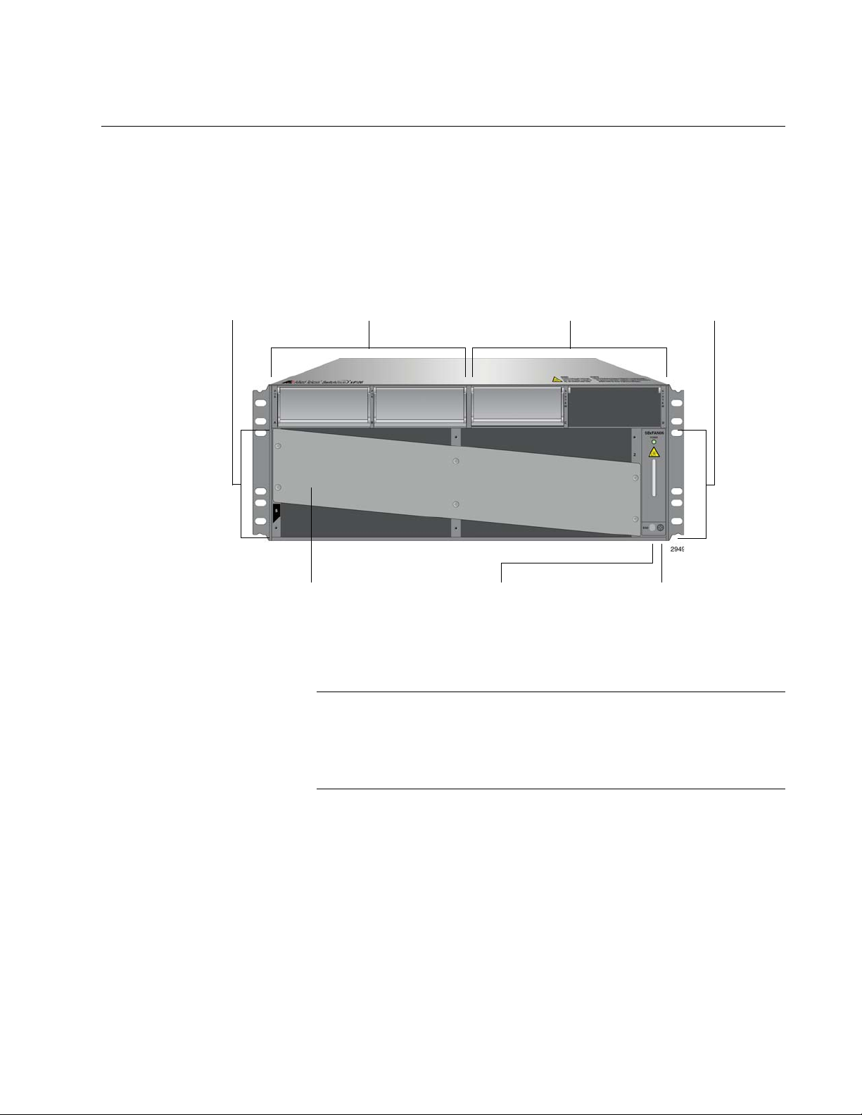
The AT-SBx8106 Chassis is a 4RU unit with slots for four Ethernet line
cards, two controller cards, two system power supply modules, and two
PoE power supply modules. The chassis components are identified in
Figure 6 here and Figure 7 on page 24.
SwitchBlade x8106 Chassis Switch Installation Guide
Figure 6. Front View of the AT-SBx8106 Chassis
Do not remove the shipping brace from the front of the chassis until
after the unit is installed in the equipment rack. You might bend the
chassis and cause misalignment of the slots and card guides if you
lift the chassis into the equipment rack without the shipping brace.
23
Page 24
Chapter 1: Overview
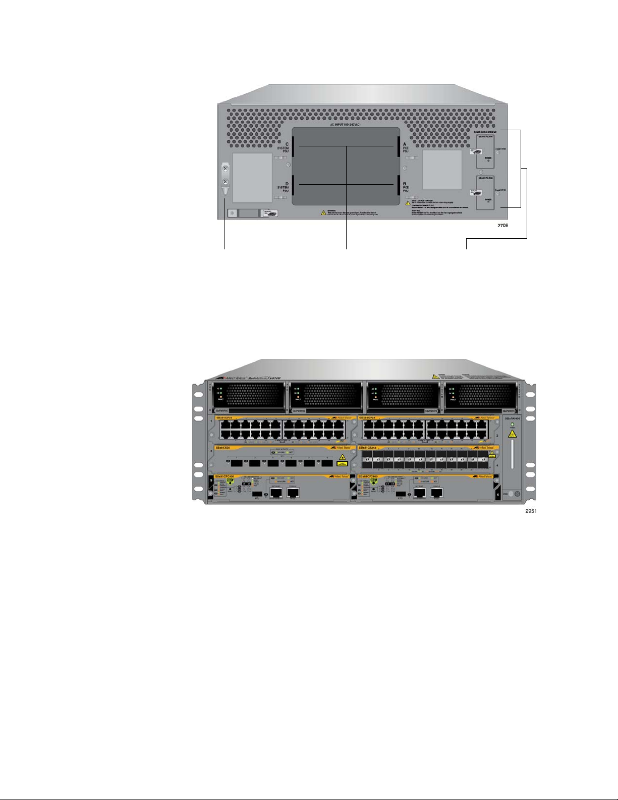
Grounding
Lug
AC Power
Cord Sockets
Power Supply
Interfaces
(Opto-couplers)
Figure 7. Rear View of the AT-SBx8106 Chassis
Ethernet Line
and Controller
Cards Slots
Figure 8 is an example of a fully populated chassis.
Figure 8. AT-SBx8106 Chassis with Line Cards, Controller Cards, and
Power Supplies
The chassis has slots for four Ethernet line cards and two ATSBx81CFC400 Controller Fabric Cards. The slot definitions are predefined
and may not be changed. Figure 9 on page 25 identifies the slots.
24
Page 25
SwitchBlade x8106 Chassis Switch Installation Guide
Slot 1 - Line Card
Slot 3 - Line Card
Slot 5 - Controller
Slot 2 - Line Card
Slot 4 - Line Card
Slot 6 - Controller
Card
Card
Slot A
AT-SBxPWRPOE1
Power Supply
Slot B
AT-SBxPWRPOE1
Power Supply
Slot C
AT-SBxPWRSYS1
Power Supply
Slot D
AT-SBxPWRSYS1
Power Supply
Figure 9. Ethernet Line and Controller Cards Slots
Slots 1 to 4 are for the Ethernet line cards. The cards may be installed in
any order or variety in the slots.
Slots 5 and 6 are for the AT-SBx81CFC400 Controller Fabric Card. The
chassis must be at least one controller card. You may add a second
controller to add redundancy or to increase the available backplane
bandwidth of the chassis. The chassis has a backplane bandwidth of 40
Gbps per slot with one controller card and 80 Gbps per slot with two cards.
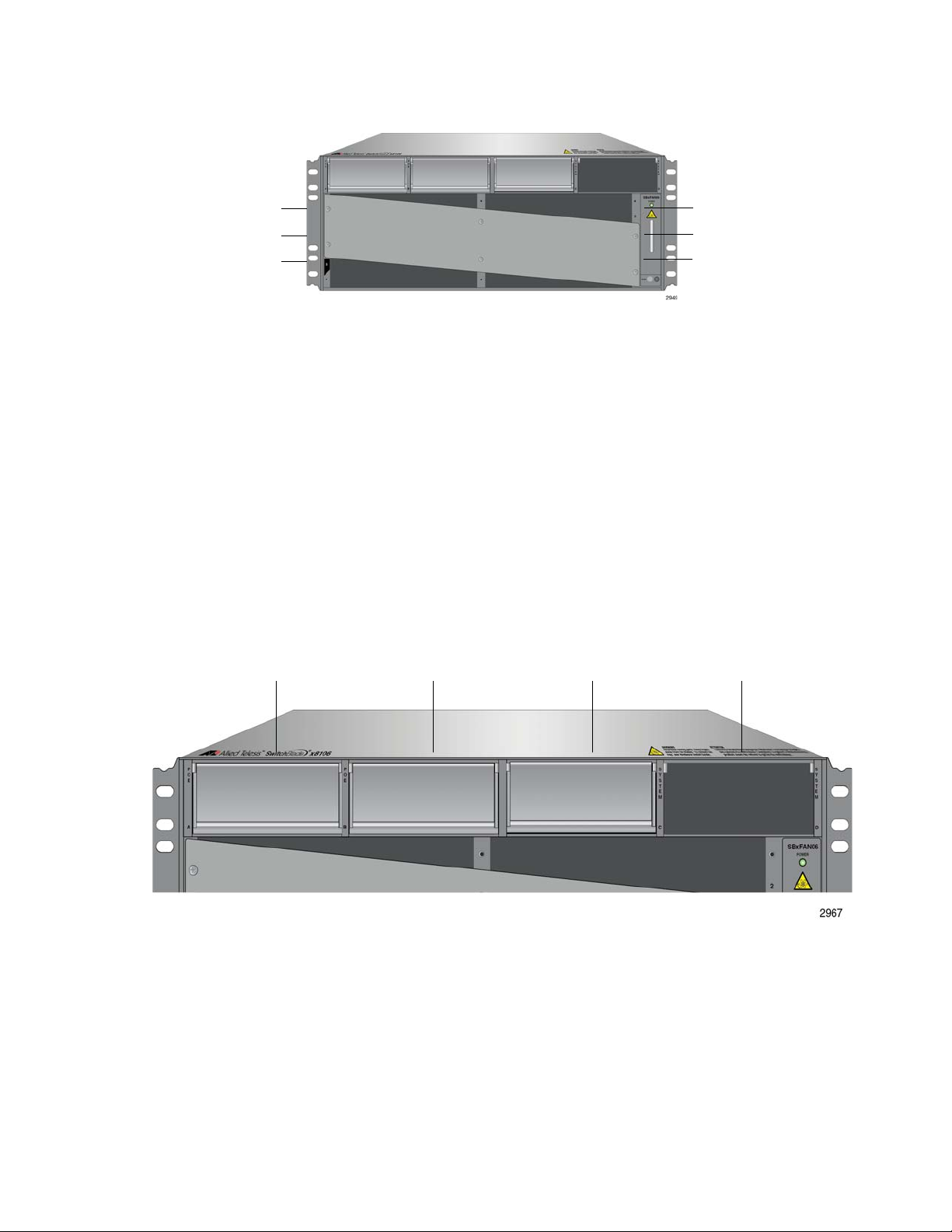
Power Supply
The chassis has four power supply slots, labelled A to D, across the top of
Slots
the front of the chassis, as shown in Figure 10.
Slots A and B are for the AT-SBxPWRPOE1 Power Supply, shown in
Figure 4 on page 21. The power supply is used to provide power to the
PoE ports on the AT-SBx81GP24 Line Card. (These slots are not used if
the chassis does not have AT-SBx81GP24 Line Cards.) There are two
slots for AT-SBxPWRPOE1 Power Supplies. You may install either one or
two modules. Installing two power supplies increases the available PoE
Figure 10. Power Supply Slots
25
Page 26

Chapter 1: Overview
Note
power so that the chassis can support more powered devices and adds
power redundancy. For more information, refer to “Power over Ethernet on
the AT-SBx81GP24 Line Card” on page 35.
Slots C and D are for the AT-SBxPWRSYS1 Power Supply, which powers
all the hardware components of the chassis, except for the PoE feature on
the ports of the AT-SBx81GP24 PoE Line Card. The chassis must have at
least one AT-SBxPWRSYS1 Power Supply. One module can power a fully
populated chassis. However, you may install two power supplies to add
power redundancy to the chassis.
There are AC and DC versions of the AT-SBxPWRSYS1 Power Supply.
Refer to Figure 4 on page 21 for illustrations of the modules.
The AT-SBxPWRSYS1 DC Power Supply is not compatible with the
AT-SBxPWRSYS1 AC or AT-SBxPWRPOE1 Power Supply. You
should not operate the chassis with both AC and DC power
supplies. You may, however, operate the chassis for a short period
of time with AC and DC power supplies if you are converting it from
one type of power supply to another, such as from AC to DC. This
allows you to transition the chassis without having to power it off.
26
Page 27
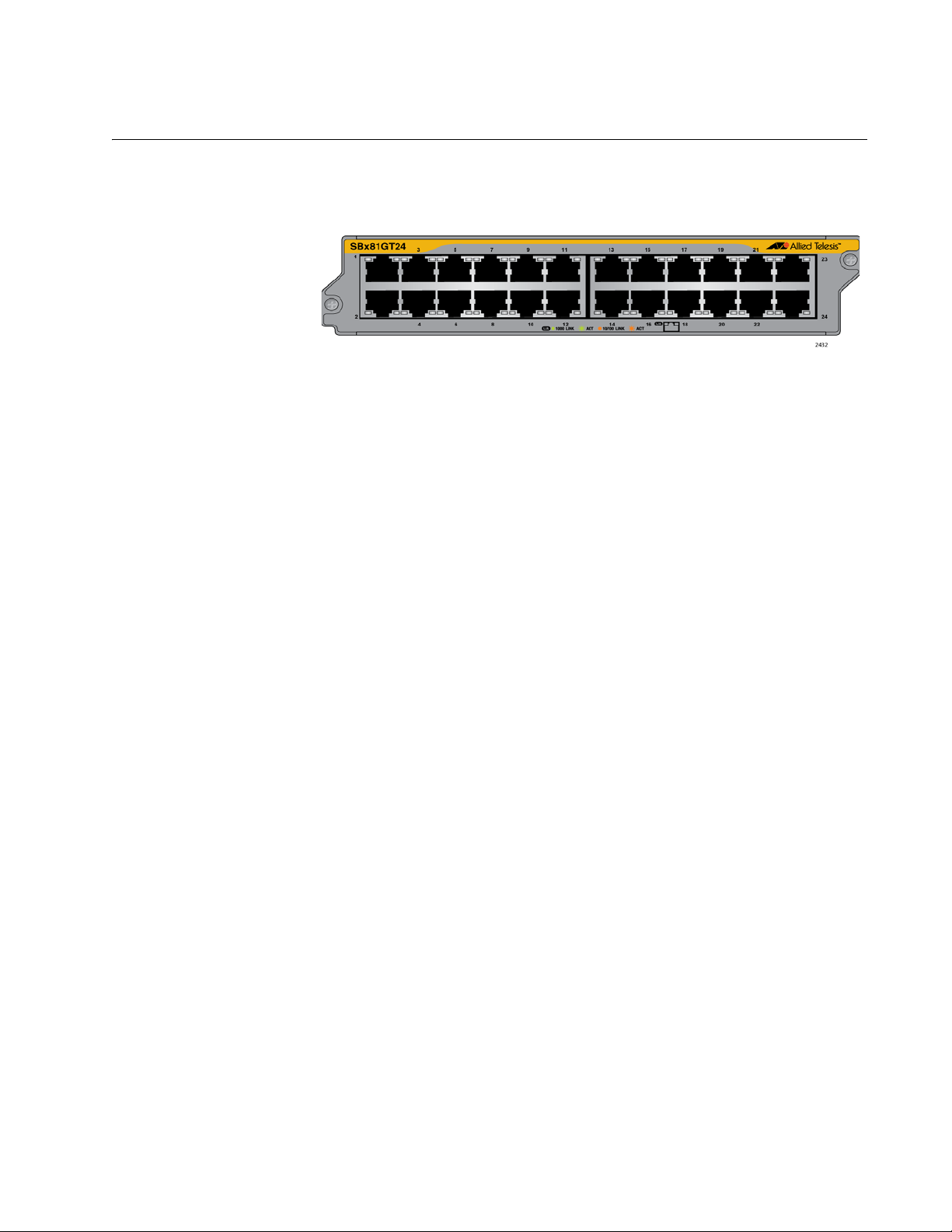
AT-SBx81GT24 Line Card
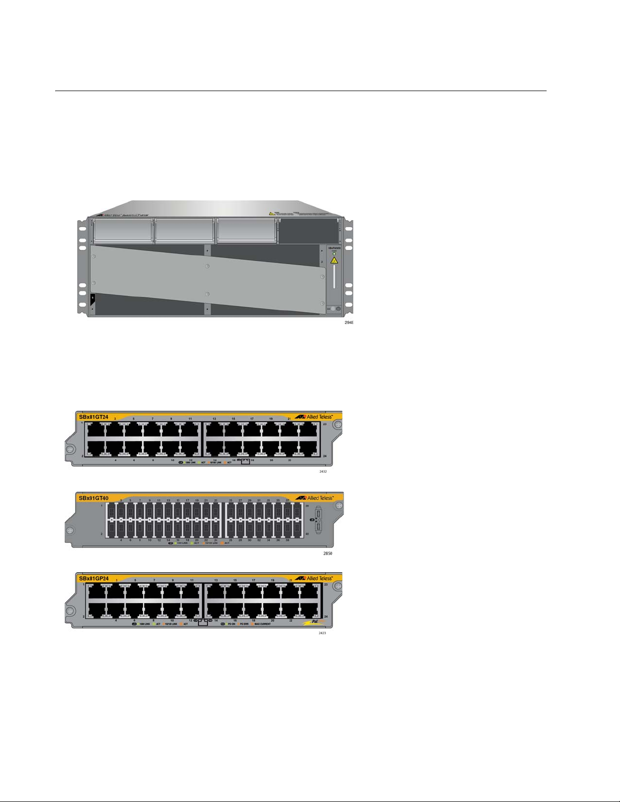
The AT-SBx81GT24 Line Card, shown in Figure 11, is a Gigabit Ethernet
switch.
Here are the main features of the line card:
24 10/100/1000Base-T ports
RJ-45 connectors
100 meters (328 feet) maximum operating distance per port
SwitchBlade x8106 Chassis Switch Installation Guide
Figure 11. AT-SBx81GT24 Line Card
Auto-Negotiation for speed and duplex mode
Automatic MDIX detection for ports operating at 10/100Base-TX,
(Automatic MDIX detection does not apply to 1000Base-T
operation.)
Port Link/Activity (L/A) LEDs
16K entry MAC address table
12 Mb buffer memory
Jumbo frame support:
– 9710 bytes for ports operating at 10 or 100 Mbps.
– 10240 bytes for ports operating at 1000 Mbps
Non-blocking full wire speed switching on all packet sizes, with two
AT-SBx81CFC400 Controller Fabric Cards
Hot swappable
The cable requirements for the ports on the AT-SBx81GT24 Line Card are
listed in Table 1 on page 33.
27
Page 28
Chapter 1: Overview
Note
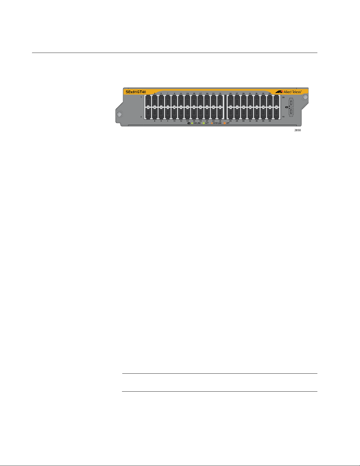
AT-SBx81GT40 Line Card
The AT-SBx81GT40 Line Card, shown in Figure 12, is a Gigabit Ethernet
switch.
Here are the main features of the line card:
40 10/100/1000Base-T ports
RJ point 5 connectors
100 meters (328 feet) maximum operating distance per port
Figure 12. AT-SBx81GT40 Line Card
Auto-Negotiation for speed
Full-duplex mode only
Automatic MDIX detection for ports operating at 10/100Base-TX,
(Automatic MDIX detection does not apply to 1000Base-T
operation.)
Port Link/Activity (L/A) LEDs
32K entry MAC address table
32 Mb buffer memory
Jumbo frame support:
– 10240 octets for tagged and untagged traffic
between ports on the same line card
– 10232 octets for untagged traffic between ports on
different line cards
– 10236 octets for tagged traffic between ports on
different line cards
Non-blocking full wire speed switching on all packet sizes, with two
AT-SBx81CFC400 Central Fabric Controller cards
Hot swappable
The ports on the line card do not support half-duplex operation.
The cable requirements for the ports on the AT-SBx81GT40 Line Card are
listed in Table 1 on page 33.
28
Page 29
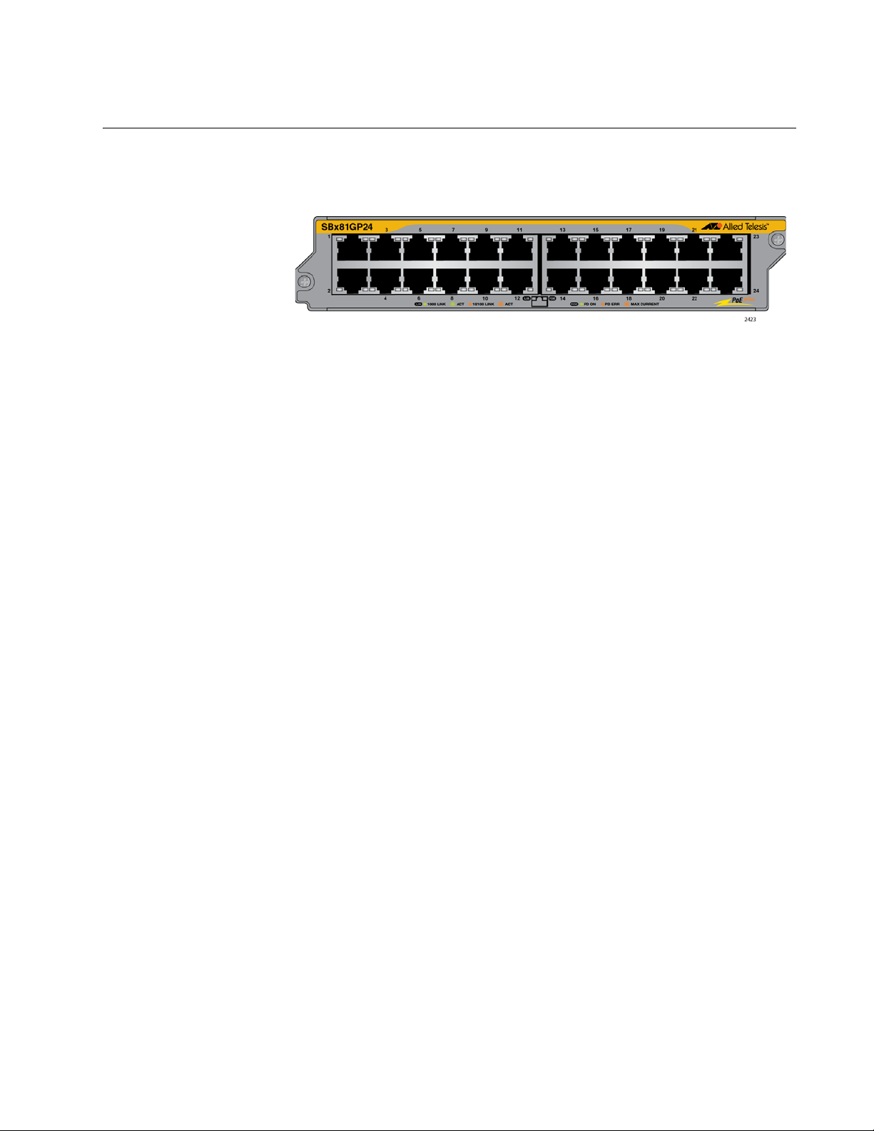
AT-SBx81GP24 PoE Line Card
The AT-SBx81GP24 PoE Line Card, shown in Figure 13, is a Gigabit
Ethernet switch with Power over Ethernet Plus (PoE+) on all the ports.
Figure 13. AT-SBx81GP24 PoE Line Card
Here are the main features of the line card:
24 10/100/1000Base-T ports
RJ-45 connectors
SwitchBlade x8106 Chassis Switch Installation Guide
100 meters (328 feet) maximum operating distance per port
Auto-Negotiation for speed and duplex mode
Automatic MDIX detection for ports operating at 10/100Base-TX,
(Automatic MDIX detection does not apply to 1000Base-T
operation.)
Port Link/Activity (L/A) and PoE+ LEDs
16K entry MAC address table
12 Mb buffer memory
PoE+ on all the ports
Up to 30W per port for PoE+
PoE device classes 0 to 4
Jumbo frame support:
– 9710 bytes for ports operating at 10 or 100 Mbps.
– 10240 bytes for ports operating at 1000 Mbps
Non-blocking full wire speed switching on all packet sizes, with two
AT-SBx81CFC400 Controller Fabric Cards
Hot swappable
The cable requirements of the PoE ports on the AT-SBx81GP24 Ethernet
Line Card are listed in Table 2 on page 34.
29
Page 30
Chapter 1: Overview
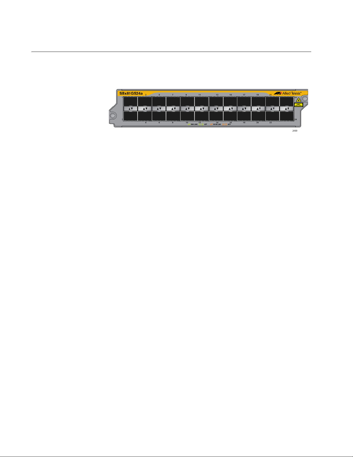
AT-SBx81GS24a SFP Line Card
The AT-SBx81GS24a SFP Line Card, shown in Figure 14, is a Gigabit
Ethernet switch.
Figure 14. AT-SBx81GS24a SFP Line Card
Here are the main features of the line card:
24 slots for small form-factor pluggable (SFP) transceivers
Supports 100Base-FX and 1000Base-SX/LX fiber optic
transceivers
Supports 100Base-BX and 1000Base-LX bidirectional (BiDi) fiber
optic transceivers
Supports 10/100/1000Base-T and 1000Base-T twisted pair
transceivers
Port Link/Activity (L/A) LEDs
32K entry MAC address table
24 Mb buffer memory
Jumbo frame support:
– 9710 bytes for ports operating at 10 or 100 Mbps.
– 10240 bytes for ports operating at 1000 Mbps
Non-blocking full wire speed switching on all packet sizes, with two
AT-SBx81CFC400 Controller Fabric Cards.
Hot swappable
Contact your Allied Telesis sales representative for a list of supported
transceivers.
30
Page 31

AT-SBx81XS6 SFP+ Line Card
The AT-SBx81XS6 Line Card, shown in Figure 15, is a 10 Gigabit Ethernet
switch.
Here are the main features of the line card:
Six slots for 10Gbps SFP+ transceivers
Supports 10GBase-SR/LR fiber optic transceivers
SwitchBlade x8106 Chassis Switch Installation Guide
Figure 15. AT-SBx81XS6 Line Card
Supports AT-SP10TW direct connect twisted pair cables with
SFP+ transceiver-style connectors
Port Link/Activity (L/A) LEDs
32K entry MAC address table
24 Mb buffer memory
Jumbo frame support:
– 9710 bytes for ports operating at 10 or 100 Mbps.
– 10240 bytes for ports operating at 1000 Mbps
Hot swappable
Contact your Allied Telesis sales representative for a list of supported
transceivers.
31
Page 32

Chapter 1: Overview
Note
Note
Note
10/100/1000Base-T Twisted Pair Ports
This section applies to the 10/100/1000Base-T ports on the ATSBx81GT24, AT-SBx81GT40, and AT-SBx81GP24 PoE Ethernet Line
Cards.
Connector Type The ports on the AT-SBx81GT24 and AT-SBx81GP24 Line Cards have 8-
pin RJ-45 connectors. The ports on the AT-SBx81GT40 Line Card have 8pin RJ point 5 connectors. The ports use four pins at 10 or 100 Mbps and
all eight pins at 1000 Mbps. The pin assignments are listed in “Port
Pinouts” on page 239.
Speed The ports can operate at 10, 100, or 1000 Mbps. The speeds can be set
automatically through Auto-Negotiation, the default setting, or manually
with the AlliedWare Plus Operating System.
Twisted-pair ports have to be set to Auto-Negotiation to operate at
1000 Mbps. You cannot manually set twisted-pair ports to 1000
Mbps.
Duplex Mode The twisted-pair ports on the AT-SBx81GT24 and AT-SBx81GP24 Line
Cards can operate in either half- or full-duplex mode at 10 or 100 Mbps.
Ports operating at 1000 Mbps can only operate in full-duplex mode. The
twisted-pair ports are IEEE 802.3u-compliant and Auto-Negotiate the
duplex mode setting.
You can disable Auto-Negotiation on the ports and set the duplex mode
manually.
Switch ports that are connected to 10 or 100 Mbps end nodes that
are not using Auto-Negotiation should not use Auto-Negotiation to
set their speed and duplex mode settings, because duplex mode
mismatches might occur. You should disable Auto-Negotiation and
set the speed and duplex mode settings manually with the
AlliedWare Plus Operating System.
The ports on the AT-SBx81GT40 Line Card only support full-duplex
mode.
32
Page 33

SwitchBlade x8106 Chassis Switch Installation Guide
Note
Maximum
Distance
Cable
Requirements
The ports have a maximum operating distance of 100 meters (328 feet).
The cable requirements for the ports on the AT-SBx81GT24 and ATSBx81GT40 Line Cards are listed in Table 1.
Table 1. Twisted Pair Cable for the AT-SBx81GT24 and AT-SBx81GT40
Line Cards
Cable Type 10Mbps 100Mbps 1000Mbps
Standard TIA/EIA 568-Bcompliant Category 3 shielded
or unshielded cabling with 100
ohm impedance and a
frequency of 16 MHz.
Standard TIA/EIA 568-Acompliant Category 5 or TIA/
EIA 568-B-compliant Enhanced
Category 5 (Cat 5e) shielded or
unshielded cabling with 100
ohm impedance and a
frequency of 100 MHz.
Yes Yes No
Yes Yes Yes
Standard TIA/EIA 568-Bcompliant Category 6 or 6a
shielded cabling.
Patch cables for the AT-SBx81GT40 Line Card, in lengths of 1 meter
and 3 meters with RJ point 5 and RJ-45 connectors, are available
from Allied Telesis. Contact your Allied Telesis sales representative
for information.
The cable requirements for the PoE ports on the AT-SBx81GP24 Ethernet
Line Card are given in Table 2 on page 34.
Yes Yes Yes
33
Page 34

Chapter 1: Overview
Table 2. Twisted Pair Cable for the AT-SBx81GP24 Line Card
10Mbps 100Mbps 1000Mbps
Cable Type
Standard TIA/EIA 568B-compliant Category 3
shielded or unshielded
cabling with 100 ohm
impedance and a
frequency of 16 MHz.
Standard TIA/EIA 568A-compliant Category 5
shielded or unshielded
cabling with 100 ohm
impedance and a
frequency of 100 MHz.
Standard TIA/EIA 568B-compliant Enhanced
Category 5 (Cat 5e)
shielded or unshielded
cabling with 100 ohm
impedance and a
frequency of 100 MHz.
Non-
PoE
Yes No No Yes No No No No No
Yes Ye s No Yes Ye s No Yes N o No
Yes Ye s Yes Ye s Yes Ye s Yes Ye s Yes
PoE PoE+
Non-
PoE
PoE PoE+
Non-
PoE
PoE PoE+
Standard TIA/EIA 568B-compliant Category 6
or 6a shielded cabling.
Automatic MDIX
Detection
Port Pinouts Refer to Table 35 on page 239 for the port pinouts of the twisted-pair ports
Yes Ye s Yes Ye s Yes Ye s Yes Ye s Yes
The 10/100/1000 Mbps twisted-pair ports on the AT-SBx81GT24, ATSBx81GT40, and AT-SBx81GP24 Line Cards are IEEE 802.3ab compliant
and feature automatic MDIX detection when operating at 10 or 100 Mbps.
(Automatic MDIX detection does not apply to 1000 Mbps.) This feature
automatically configures the ports to MDI or MDI-X depending on the
wiring configurations of the end nodes.
Ports connected to network devices that do not support automatic MDIX
detection default to MDIX.
You may disable automatic MDIX detection on the individual ports and
configure the MDI/MDI-X settings manually with the POLARITY command.
when they operate at 10 or 100 Mbps in the MDI configuration and
Table 36 on page 239 for the MDI-X configuration. For port pinouts when
the twisted-pair ports operate at 1000 Mbps, refer to Table 37 on
page 240.
34
Page 35

SwitchBlade x8106 Chassis Switch Installation Guide
Power over Ethernet on the AT-SBx81GP24 Line Card
This section applies to the AT-SBx81GP24 PoE Line Card. The twistedpair ports on the line card support Power over Ethernet (PoE). PoE is a
mechanism by which the ports supply power to network devices over the
twisted pair cables that carry the network traffic. This feature can simplify
network installation and maintenance because it allows you to use the
switch as a central power source for other network devices.
Devices that receive their power over Ethernet cables are called powered
devices (PD), examples of which include wireless access points, IP
telephones, web cams, and even other Ethernet switches. A PD
connected to a port on the switch receives both network traffic and power
over the same twisted-pair cable.
The AT-SBx81GP24 Line Card automatically determines whether a device
connected to a port is a PD. A PD has a signature resistor or signature
capacitor that the line card can detect over the Ethernet cabling. If the
resistor or capacitor is present, the switch assumes that the device is a
PD.
Powered Device
Classes
A port connected to a network node that is not a PD (that is, a device that
receives its power from another power source) functions as a regular
Ethernet port, without PoE. The PoE feature remains enabled on the port
but no power is delivered to the device.
The IEEE 802.3af and 802.3at standards define five powered device
classes. The classes are defined by the power requirements of the
powered devices. The classes are shown in Table 3. The AT-SBx81GP24
Line Card supports all five classes.
Table 3. IEEE802.3af and IEEE802.3at Powered Device Classes
Maximum
Class Usage
0 Default 15.4W .044W to
1 Optional 4.0W 0.44W to 3.84W
2 Optional 7.0W 3.84W to 6.49W
Power Output
on the PoE
Port
PD Power
Range
12.95W
3 Optional 15.4W 6.49W to
12.95W
4 Optional 30.0W 12.95W to
25.9W
35
Page 36

Chapter 1: Overview
Note
Note
Power Budgeting The power for PoE on the ports on the AT-SBx81GP24 Line Card is
provided by the AT-SBxPWRPOE1 Power Supply. It can provide up to
1200 watts of power for powered devices. You may install up to two power
supplies in the chassis for a total of 2400 watts for the powered devices.
The number of powered devices the chassis can support at one time
depends on the number of AT-SBxPWRPOE1 Power Supplies in the
chassis and the power requirements of the powered devices in your
network. Table 4 lists the maximum number of powered devices by class,
for one or two power supplies. The numbers assume that the powered
devices require the maximum amount of power for their classes.
The maximum number of PoE ports in the SwitchBlade x8106
Switch is 96 ports.
Table 4. Maximum Number of Powered Devices
Maximum Number of
Class
07796
19696
29696
37796
44080
Ports with
One PoE PSU
(1200 W)
Maximum Number of
Ports with
Two PoE PSU’s
(2400 W)
PoE Wiring The IEEE 802.3af and 802.3at standards define two methods for
delivering power to powered devices over the four pairs of strands that
comprise a standard Ethernet twisted-pair cable. The methods are called
Alternatives A and B. In Alternative A, power is supplied to powered
devices on strands 1, 2, 3, and 6, which are the same strands that carry
the 10/100Base-TX network traffic. In Alternative B, power is delivered on
strands 4, 5, 7, and 8. These are the unused strands.
1000BASE-T cables carry the network traffic on all eight strands of
the Ethernet cable.
The PoE implementation on the AT-SBx81GP24 Line Card is Alternative
A. Power is transmitted on strands 1, 2, 3, and 6.
36
Page 37

SwitchBlade x8106 Chassis Switch Installation Guide
PDs that comply with the IEEE 802.3af and 802.3at standards typically
support both power delivery methods. However, some legacy PDs support
only one power delivery method. Legacy devices that only support
Alternative B will not work with the AT-SBx81GP24 PoE Line Card. Legacy
devices are nodes manufactured before the IEEE 802.3af and 802.3at
standards were completed and, consequently, may not adhere to the
standards.
37
Page 38

Chapter 1: Overview
Port LEDs on the Ethernet Line Cards
The following sections define the port LEDs on the Ethernet line cards.
AT-SBx81GT24
Line Card
Each port on the AT-SBx81GT24 Line Card has two LEDs. The LEDs are
shown in Figure 16 and described in Table 5.
Figure 16. Port LEDs on the AT-SBx81GT24 Line Card
Table 5. Port LEDs on the AT-SBx81GT24 Line Card
LED State Description
Solid Green The port has established an 1000 Mbps link
to a network device.
L/A
Flashing
Green
Solid Amber The port has established a 10 or 100 Mbps
Flashing
Amber
Off The port has not established a link with
The port is transmitting or receiving data at
1000 Mbps.
link to a network device.
The port is transmitting or receiving data at
10 or 100.
another network device or the LEDs are
turned off. To turn on the LEDs, use the
eco-friendly button.
38
Page 39
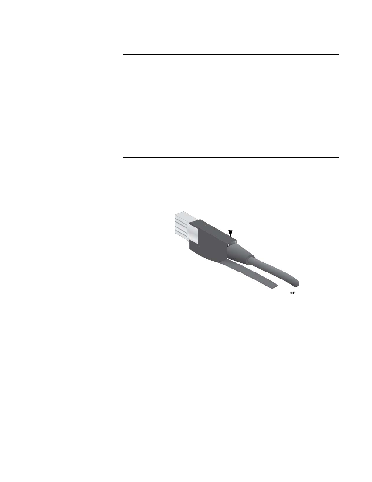
SwitchBlade x8106 Chassis Switch Installation Guide
LEDs
Table 5. Port LEDs on the AT-SBx81GT24 Line Card (Continued)
LED State Description
Solid Green The port is operating in full duplex mode.
Solid Amber The port is operating in half duplex mode.
Duplex
Mode
Flashing
amber
Off The port has not established a link with
The port is operating in half duplex mode,
with collisions.
another network device or the LEDs are
turned off. To turn on the LEDs, use the
eco-friendly button.
AT-SBx81GT40
Line Card
The LEDs for a port on the AT-SBx81GT40 Line Card are found on the RJ
point 5 cable connector. The LEDs are shown in Figure 17.
Figure 17. Port LEDs on an RJ Point 5 Cable Connector for the AT-
SBx81GT40 Line Card
Only the left LED is active. Refer to Figure 18 on page 40. It displays link
and activity information about a port. The states of the LED are defined in
Table 6 on page 40.
39
Page 40

Chapter 1: Overview
L/A LEDs
Figure 18. Port LEDs on an RJ Point 5 Cable Connector for the AT-
SBx81GT40 Line Card
Table 6. Port LEDs on the AT-SBx81GT40 Line Card
LED State Description
Solid Green The port has established an 1000 Mbps link
to a network device.
L/A
Flashing
Green
The port is transmitting or receiving data at
1000 Mbps.
Solid Amber The port has established a 10 or 100 Mbps
link to a network device.
Flashing
Amber
The port is transmitting or receiving data at
10 or 100.
Off The port has not established a link with
another network device or the LEDs are
turned off. To turn on the LEDs, use the
eco-friendly button.
40
Right LED - This LED is not used.
Page 41
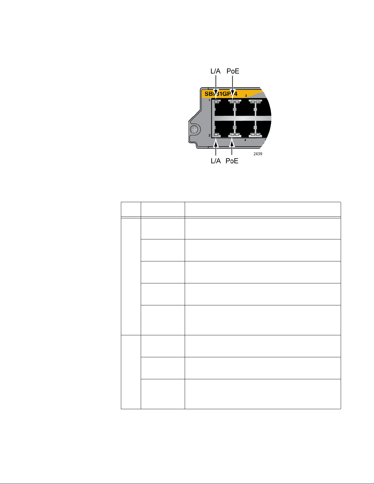
SwitchBlade x8106 Chassis Switch Installation Guide
AT-SBx81GP24
Line Card
Each port on the AT-SBx81GP24 PoE Line Card has two LEDs. The LEDs
are shown in Figure 19 and described in Table 7.
Figure 19. Port LEDs on the AT-SBx81GP24 PoE Line Card
Table 7. Port LEDs on the AT-SBx81GP24 PoE Line Card
LED State Description
Solid Green The port has established an 1000 Mbps link to a
network device.
L/A
PoE
Flashing
Green
Solid Amber The port has established a 10 or 100 Mbps link to
Flashing
Amber
Off The port has not established a link with another
Green The switch is detecting a powered device (PD) on
Solid Amber The switch has shutdown PoE+ on the port
Flashing
Amber
The port is transmitting or receiving data at 1000
Mbps.
a network device.
The port is transmitting or receiving data at 10 or
100 Mbps.
network device or the LEDs are turned off. To turn
on the LEDs, use the eco-friendly button.
the port and is delivering power to it.
because of a fault condition.
The switch is detecting a PD on the port but is not
delivering power to it because the maximum power
budget has been reached.
41
Page 42

Chapter 1: Overview
Table 7. Port LEDs on the AT-SBx81GP24 PoE Line Card (Continued)
LED State Description
PoE Off This LED state can result from the following
conditions:
The port is not connected to a PD.
The PD is powered off.
The port is disabled in the management
software.
PoE is disabled on the port.
The LEDs on the Ethernet line cards are
turned off. To turn on the LEDs, use the
eco-friendly button.
AT-SBx81GS24a
Line Card
The SFP slots on the AT-SBx81GS24a SFP Line Card have one LED
each, as shown in Figure 20 and described in Table 8.
Figure 20. Port LEDs on the AT-SBx81GS24a SFP Line Card
Table 8. Port LEDs on the AT-SBx81GS24a SFP Line Card
LED State Description
Solid Amber
The SFP transceiver in the slot has established a
10 or 100 Mbps link to a network device.
42
Blinking Amber
Solid Green
Blinking Green
The SFP transceiver is transmitting and/or
receiving data at 10 or 100 Mbps.
The SFP transceiver in the slot has established
an 1000 Mbps link to a network device.
The SFP transceiver is transmitting and/or
receiving data at 1000 Mbps.
Page 43

SwitchBlade x8106 Chassis Switch Installation Guide
Table 8. Port LEDs on the AT-SBx81GS24a SFP Line Card (Continued)
Off This LED state can result from the following
conditions:
The transceiver slot is empty.
The transceiver has not established a link
with a network device.
The LEDs on the Ethernet line cards are
turned off. To turn on the LEDs, use the
eco-friendly button.
AT-SBx81XS6
Line Card
The AT-SBx81XS6 Line Card has one LED for each SFP+ slot. The LED
is shown in Figure 21 and described in Table 9.
Figure 21. SFP+ Slot LEDs on the AT-SBx81XS6 Line Card
Table 9. SFP+ Slot LEDs on the AT-SBx81XS6 Line Card
LED State Description
Solid Green The transceiver has established a link with a
network device.
L/A
Flashing
Green
The transceiver is transmitting or receiving data at
10 Gbps.
Off This LED state can result from the following
conditions:
The transceiver slot is empty.
The transceiver has not established a link
with a network device.
The LEDs on the Ethernet line cards are
turned off. To turn on the LEDs, use the
eco-friendly button.
43
Page 44

Chapter 1: Overview
AT-SBx81CFC400 Controller Fabric Card
The AT-SBx81CFC400 Controller Fabric Card has three primary
functions:
Chassis Management — You may use the controller card to
monitor and configure the Ethernet line cards in the chassis. You
may manage the chassis locally through the Console RS-232 port
on the controller card or remotely using Telnet, Secure Shell
(SSH), and SNMP clients from workstations on your network.
AlliedWare Plus Operating System and Configuration Settings —
The controller card stores the AlliedWare Plus Operating System
and configuration settings for the Ethernet line cards in the chassis
and downloads the files to the cards when the chassis is powered
on or new line cards are installed. The settings are stored in a
database file in nonvolatile memory so that they are retained even
when the chassis is reset or powered off.
Backplane Controller — The controller card manages the
backplane of the chassis, which the line cards use to forward traffic
to each other.
A single controller card provides 40 Gbps of backplane bandwidth
per line card slot. You may install a second controller card for 80
Gbps of backplane bandwidth per line card slot.
Here are the guidelines to the controller card:
The chassis must have at least one controller card. The line cards
do not forward traffic if the chassis does not have a controller card.
The chassis may have either one or two controller cards.
Two controller cards are recommended for redundancy and to
increase the backplane bandwidth from 40 to 80 Gbps per line
card slot.
Controller cards must be installed in slots 5 and 6 in the chassis.
Here are other features of the AT-SBx81CFC400 Controller Fabric Card:
LEDs for monitoring the status of the Ethernet line cards.
Power-saving eco-friendly button for turning the port and status
LEDs on or off on the line cards and controller cards.
Reset switch for resetting the chassis.
USB port for data storage and retrieval.
44
Console RS-232 for local management.
NET MGMT port for remote Telnet, SSH, and SNMP management.
Hot swappable.
Page 45
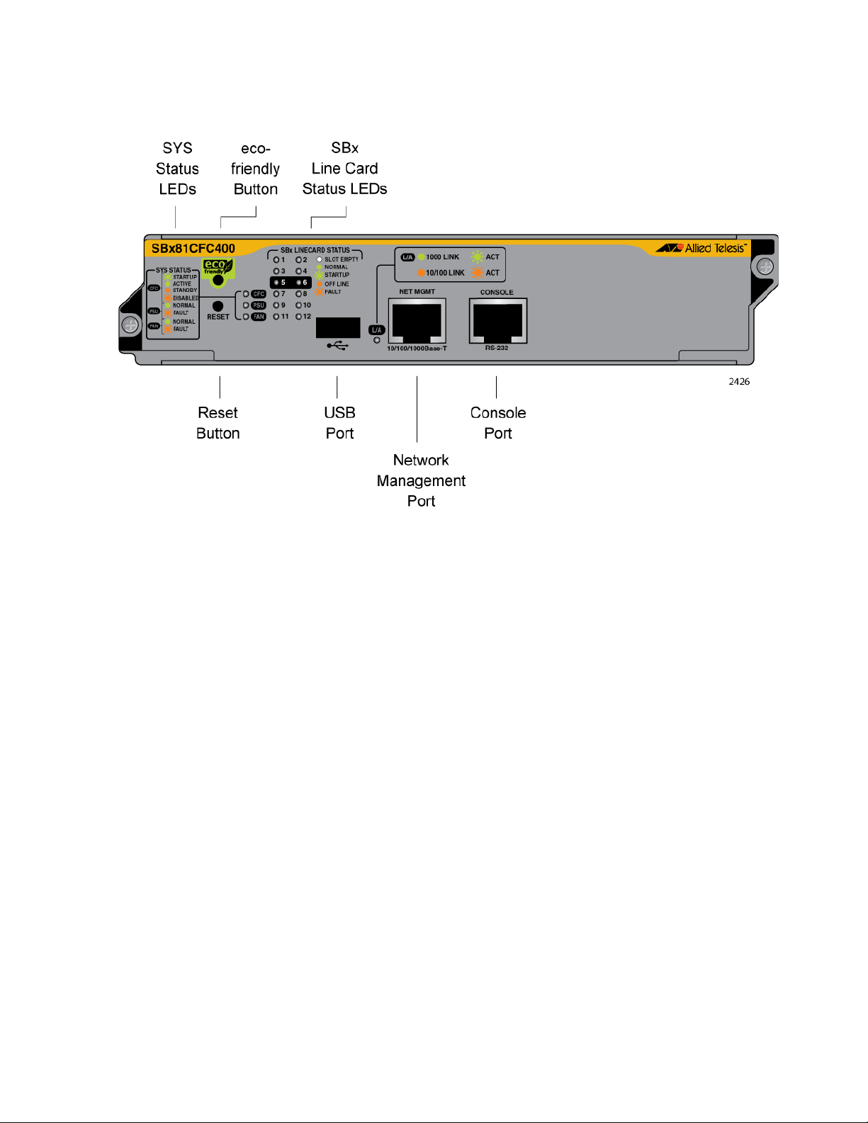
SwitchBlade x8106 Chassis Switch Installation Guide
The components on the card are identified in Figure 22.
Figure 22. AT-SBx81CFC400 Controller Fabric Card
Where two controller cards are installed in the chassis, they provide an
active/active architecture. The packet processors on both controller cards
are fully utilized to double the available backplane bandwidth from 40 to 80
Gbps per Ethernet line card.
One of the controller cards becomes the active master. In normal
operations, this is the controller card in slot 5. The active master manages
the system and processes CPU bound network traffic. The standby master
runs all network protocol modules and is kept in sync with the active
master card, so as to be available in hot-standby for near instantaneous
fail over, if required.
If the active master card is hot-swapped out, the standby master becomes
the active master. It takes over all control functions almost
instantaneously. Testing has shown no noticeable disruption to streaming
video.
You can determine the state of the controller card by viewing the CFC LED
on the card. The controller card is the active master when the LED is solid
green and the standby master when the LED is solid amber.
SYS Status LEDs The SYS (System) Status LEDs on the controller fabric card display
general status information about the controller card, power supplies, and
fan module. The LEDs are defined in Table 10 on page 46.
45
Page 46

Chapter 1: Overview
Table 10. SYS (System) Status LEDs
LED State Description
Solid Green Indicates that the AT-SBx81CFC400 Controller
Fabric Card is operating normally as the active
master controller card.
CFC
PSU
Flashing
Green
Indicates that the controller card is initializing its
AlliedWare Plus Operating System or
synchronizing its database with the active master
controller card.
Solid
Amber
Flashing
Amber
Indicates that the controller card is operating
normally as the standby master controller card.
Indicates that the controller card is disabled. This
state might occur if the standby master controller
card is disabled by the active master controller
card because the two cards have incompatible
versions of the AlliedWare Plus Operating System
and are unable to resolve the problem, possibly
because of insufficient free flash memory.
Solid Green Indicates that the power supplies are operating
properly.
Flashing
Amber
Indicates that a power supply is experiencing a
problem. Possible causes are:
The input AC voltage from a power source is
not within the normal operating range of a
power supply module.
46
FAN
The output DC voltage from a power supply
module to the line cards is not within the
normal operating range.
A power supply is experiencing high
temperature.
A power supply has failed.
Check the status LEDs on the individual power
supply modules to determine which module has a
fault condition.
Solid Green Indicates that the fan module is operating properly.
Flashing
Amber
Indicates that the fan module has a problem. The
fans are operating below the normal operating
range or have stopped.
Page 47

SwitchBlade x8106 Chassis Switch Installation Guide
SBx STATUS
LEDs
The SBx LINECARD STATUS LEDs display general status information
about the Ethernet line cards and controller cards. There are twelve LEDs,
numbered 1 to 12. Only LEDs 1 to 6 are used. They correspond to slots 1
to 6 in the AT-SBx8106 Chassis. LEDs 7 to 12 are not used. If the chassis
has two controller cards, the SBx Status LEDs are active on both cards.
The LEDs are defined in Table 11.
Table 11. SBx LINECARD STATUS LEDs
LEDs State Description
Solid Green Indicates that the Ethernet line or controller
card is operating normally.
1 to 12
Flashing Green Indicates that the card is booting up,
running in test mode, or loading its
configuration settings.
Solid Amber Indicates that the card is in an off-line state.
Possible causes are:
An Ethernet line card that displays this
LED state may have encountered a
problem initializing the management
software.
An Ethernet line card that displays this
LED state might not be able to boot up
because the controller card does not
have the appropriate load file and
needs to be updated to the most recent
release of the management software.
A standby master controller card that
displays this LED state may have been
disabled by the active master controller
card because the cards have
incompatible versions of the
management software and were unable
to resolve the problem, possibly
because of insufficient free flash
memory.
You may remove a line or controller card
from the chassis when it is in this state.
Flashing Amber Indicates that the card is reporting a fault
condition. Use the management commands
to determine the specific problem.
47
Page 48

Chapter 1: Overview
Caution
Table 11. SBx LINECARD STATUS LEDs (Continued)
LEDs State Description
Off Indicates one of the following:
1 to 12
The slot is empty.
The LED is not used.
The LEDs are turned off. To turn on the
LEDs, use the eco-friendly button.
eco-friendly
Button
You may use the eco-friendly button on the controller card to turn the
LEDs on or off. You may turn off the LEDs when you are not using them to
monitor the control and Ethernet line cards, to conserve electricity. When
the LEDs are off, the overall power consumption of the chassis is slightly
reduced, approximately 3 watts in a system with 240 active copper ports.
The button controls all of the port LEDs on the Ethernet line cards and
controller card, except for the CFC LED, which is always on, and the L/A
LED for the NET MGMT port. The button does not control the LEDs on the
fan module and power supply systems.
Reset Button You may use the Reset button to reset the controller card or all the cards
in the chassis. The action depends on the number of AT-SBx81CFC400
Controller Cards in the chassis and, if the chassis has two controller cards,
whether you reset the active or standby master controller card.
The possible actions are described here:
48
If the chassis has only one controller card, pressing the Reset
button resets the controller card and all of the Ethernet line cards in
the chassis. You may perform this function if the chassis and line
cards are experiencing a problem.
The control and Ethernet line cards do not forward network traffic for
a minimum of two minutes while they initialize their AlliedWare Plus
Operating System and configure their parameter settings. Some
network traffic may be lost.
If the chassis has two controller cards, pressing the Reset button
on the active master controller card resets the controller card, but
not the Ethernet line cards. The standby master controller card
immediately becomes the new active master card and the Ethernet
line cards continue to forward traffic. The reset controller card is
unavailable for about two minutes while it initializes its AlliedWare
Plus Operating System, after which it becomes the standby master
controller card in the chassis.
Page 49

SwitchBlade x8106 Chassis Switch Installation Guide
Note
Note
Note
The available bandwidth across the backplane of the chassis is
reduced from 80 Gbps per slot to 40 Gbps per slot for about one
minute while the reset controller card initializes its AlliedWare Plus
Operating System. This may reduce network performance.
If the chassis has two controller cards, pressing the Reset button
on the standby master controller card resets that card, but not the
active master controller card or the Ethernet line cards.
The available bandwidth across the backplane of the chassis is
reduced from 80 to 40 Gbps per line card slot for about one minute
while the standby master controller card initializes its AlliedWare
Plus Operating System and synchronizes its database with the
active master controller card. This may reduce network
performance.
NET MGMT
Port
To reset individual line cards in the chassis, use the REBOOT or
RELOAD command in the AlliedWare Plus Operating System.
The NET MGMT port is a standard 10/100/1000Base-T Ethernet port. You
may use it as an alternative to the ports on the Ethernet line cards for
support of the features in Table 12 on page 50. You may connect the port
to a router, switch, media converter, workstation, server, or other network
device.
The controller card uses the port as a standard network link for data
reception and transmission. It is used only by the controller card and
cannot be accessed from the line cards in the unit.
When the controller card performs a feature in Table 12, it establishes a
data link with the corresponding network device using either the NET
MGMT port or a port on an Ethernet line card. For example, when you
manage the switch remotely using its Telnet server, the data link between
the Telnet client on your workstation and the server on the controller card
is established either on the NET MGMT port or a port on an Ethernet line
card, wherever the Telnet client is located.
You are not required to use the NET MGMT to use the features in
Table 12 on page 50. The controller card can communicate with network
devices, such as Telnet clients, FTP server, and SNTP server, over the
ports on the Ethernet line cards.
For instructions on how to configure the NET MGMT port, refer to the
Software Reference for SwitchBlade x8100 Series Switches.
49
Page 50

Chapter 1: Overview
Table 12. Features that Use the NET MGMT Port
Feature Description
Ping Used to test the NET MGMT port
for network connectivity.
FTP client Used with an FTP server on your
network to download files to or
upload files from the controller
card.
RADIUS client Used for remote management
authentication and 802.1x portbased network access control.
RMON with SNMP Used with the RMON portion of
the MIB tree on an SNMP
workstation to remotely monitor
the switch.
Secure Shell server Used to remotely manage the
chassis with a Secure Shell client.
SNMPv1 and v2c Used to remotely manage the
chassis with SNMP.
SNTP client Used to set the date and time on
the controller card, from an NTP or
SNTP server on your network or
the Internet.
Syslog client Used to send the event messages
from the controller card to syslog
servers on the network.
TACACS+ client Used with a TACACS+ server on
your network for remote
management authentication.
Telnet server Used to remotely manage the
chassis with a Telnet client.
TFTP client Used to download files to or
upload files from the controller
card with TFTP.
50
TRACEROUTE Used to determine the
intermediate nodes (or hops) of
network paths.
Page 51

SwitchBlade x8106 Chassis Switch Installation Guide
The NET MGMT port has a standard RJ-45 8-pin connector and operates
at 10, 100, or 1000 Mbps in either half- or full-duplex mode. The cable
requirements for this port are the same as the ports on the ATSBx81GT24 Line Card, listed in Table 1 on page 33. For the port pinouts,
refer to “Port Pinouts” on page 239.
The default setting for the port is Auto-Negotiation, which sets the speed
and duplex mode automatically. You may disable Auto-Negotiation and
configure the port manually. The port is referred to as ETH0 in the
AlliedWare Plus Operating System.
The wiring configuration of the NET MGMT port is set automatically with
automatic MDIX detection. You may disable automatic MDIX detection
and set the wiring configuration manually.
NET MGMT
LED
Console (RS-232)
Port
The Network Management (NET MGMT) port on the AT-SBx81CFC400
Controller Fabric Card has one Status LED, described in Table 13.
Table 13. NET MGMT Port LED
LED State Description
Solid Green The port has a valid 1000 Mbps link.
Flashing
Green
L/A
The Console Port is used to conduct local management sessions with the
switch. Local management sessions are established with a terminal or PC
with a terminal emulation program, and the management cable that comes
with the card.
Solid Amber The port has a valid 10 or 100 Mbps link.
Flashing
Amber
Off The port has not established a link to a
The port is transmitting or receiving data at
1000 Mbps.
The port is transmitting or receiving data at
10 or 100 Mbps.
network device.
Local management is referred to as out-of-band management because it
is not conducted over a network. Consequently, the AT-SBx81CFC400
Controller Fabric Card does not need an Internet Protocol (IP) address for
this type of management.
Your initial management session with the switch must be a local
management session. For instructions on how to start a local management
session, refer to “Using Local Management to Verify the Chassis” on
page 184 or the Software Reference for SwitchBlade x8100 Series
Switches.
51
Page 52

Chapter 1: Overview
USB Port The USB port supports a flash drive. You may use a flash drive to perform
the following management functions:
Store backup copies of the master configuration and database files
on the AT-SBx81CFC400 Controller Fabric Card.
Transfer master configuration files between controller cards in
different chassis that are to have similar configurations.
Transfer application load files between controller cards.
Store streaming log files.
Boot the AlliedWare Plus Operating System and master
configuration file from flash drive.
The port is compatible with USB v1.0 and v2.0 flash drives. Operating the
controller card with a flash drive is optional.
52
Page 53

AT-SBxPWRSYS1 AC Power Supply
The AT-SBxPWRSYS1 AC Power Supply, shown in Figure 23, is the
power supply unit for the chassis. It supplies power to all the hardware
components in the chassis, except for the PoE feature on the ports on the
AT-SBx81GP24 Line Cards. The PoE feature is powered by the ATSBxPWRPOE1 Power Supply.
SwitchBlade x8106 Chassis Switch Installation Guide
Figure 23. AT-SBxPWRSYS1 AC Power Supply
A single AT-SBxPWRSYS1 Power Supply can support a fully populated
chassis, with any combination of Ethernet line cards. The chassis can
have two AT-SBxPWRSYS1 Power Supplies for power redundancy.
Power supply modules are not included with the chassis and must be
purchased separately.
The AT-SBxPWRSYS1 Power Supplies are installed in the two right hand
slots, labeled C and D, at the top of the front of the chassis. If you are
installing just one power supply, you may install it in either slot. The
locations of the slots are shown in Figure 6 on page 23.
The AT-SBxPWRSYS1 Power Supply is hot swappable. If a chassis has
two power supplies and one of them fails, you may replace the failed unit
without having to power off the chassis.
LEDs The LEDs on the AT-SBxPWRSYS1 are described in Table 14.
Table 14. AT-SBxPWRSYS1 Power Supply LEDs
LED State Description
AC
Solid Green The power supply is receiving AC power that is
within the normal operating range.
Off The power supply is not receiving power from the
AC power source.
53
Page 54

Chapter 1: Overview
Table 14. AT-SBxPWRSYS1 Power Supply LEDs (Continued)
LED State Description
Solid Green The power supply is providing DC power that is
within the normal operating range.
DC
Off The power supply is not generating DC power or
the power is outside the normal operating range.
Solid Amber A power supply has detected a fault condition,
such as an under-voltage, or over-temperature
Fault
condition.
Off The power supply is operating normally or is
powered off.
54
Page 55
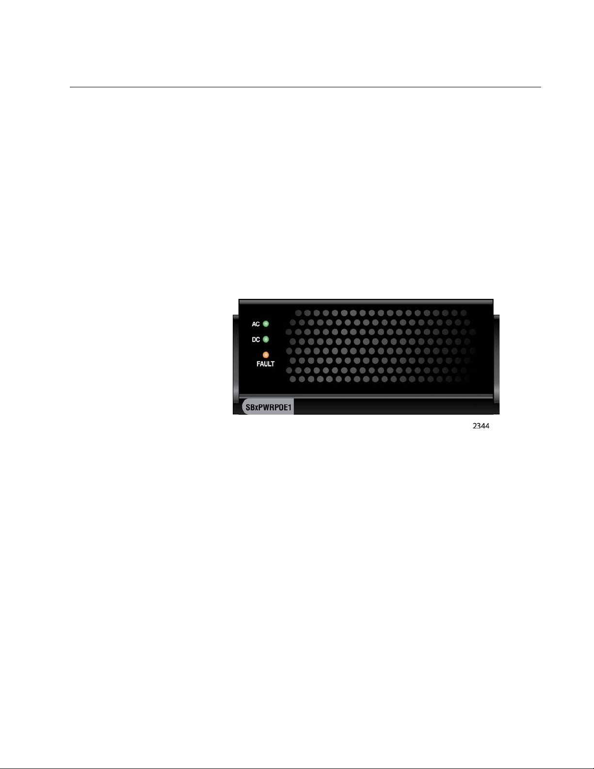
AT-SBxPWRPOE1 Power Supply
The AT-SBxPWRPOE1 Power Supply, shown in Figure 24, provides the
PoE power for the ports on the AT-SBx81GP24 PoE Line Cards. You may
install either one or two PoE power supplies in the chassis.
The AT-SBxPWRPOE1 Power Supply provides 1200 watts of power for
PoE. You may install two power supplies in the chassis for a total of 2,400
watts of power.
The total number of powered devices the chassis can support depends on
the number of AT-SBxPWRPOE1 Power Supplies in the chassis and the
power requirements of the devices. For instance, a chassis can support 40
ports of Class 4, PoE+ (IEEE 802.3at) powered devices with one power
supply or 80 ports with two power supplies. For further information, refer to
Table 4 on page 36.
SwitchBlade x8106 Chassis Switch Installation Guide
Figure 24. AT-SBxPWRPOE1 Power Supply
Power supply modules are not included with the chassis and must be
purchased separately.
The AT-SBxPWRPOE1 Power Supplies are installed in the two left hand
slots, labeled A and B, at the top of the front of the chassis. If you are
installing only one power supply, you may install it in either slot. The
locations of the slots are shown in Figure 6 on page 23.
The AT-SBxPWRPOE1 Power Supply is hot swappable. You do not have
to power off the chassis to install or remove the power supply.
LEDs The LEDs on the AT-SBxPWRPOE1 Power Supply are described in
Table 15 on page 56.
55
Page 56

Chapter 1: Overview
Table 15. AT-SBxPWRPOE1 Power Supply LEDs
LED State Description
Solid Green The power supply is receiving AC power that is
within the normal operating range.
AC
Off The power supply is not receiving power from the
AC power source.
Solid Green The DC power provided by the power supply to
the line cards over the backplane is within the
normal operating range.
DC
Off The power supply is not providing any DC power
or the power is not within the normal operating
range.
Solid Amber The power supply has detected a fault condition,
such as an under-voltage or over-temperature
Fault
condition.
Off The power supply is operating normally or is
powered off.
56
Page 57

AT-SBxPWRSYS1 DC Power Supply
Note
The AT-SBxPWRSYS1 DC Power Supply, shown in Figure 25, is a DC
version of the power supply unit for the chassis and may be used in place
of the AT-SBxPWRSYS1 AC Power Supply in network environments that
have DC wiring. Like the AC power supply, the module supplies power to
all the hardware components in the chassis, except for the PoE feature on
the ports on the AT-SBx81GP24 Line Cards.
SwitchBlade x8106 Chassis Switch Installation Guide
Figure 25. AT-SBxPWRSYS1 DC Power Supply
A single AT-SBxPWRSYS1 Power Supply can support a fully populated
chassis, with any combination of Ethernet line cards. The chassis can
have two AT-SBxPWRSYS1 Power Supplies for power redundancy.
Power supply modules are not included with the chassis and must be
purchased separately.
The AT-SBxPWRSYS1 Power Supplies are installed in the two right hand
slots, labeled C and D, at the top of the front of the chassis. If you are
installing just one power supply, you may install it in either slot. The
locations of the slots are shown in Figure 6 on page 23.
The AT-SBxPWRSYS1 Power Supply is hot swappable. If a chassis has
two power supplies and one of them fails, you may replace the failed unit
without having to power off the chassis.
The AT-SBxPWRSYS1 DC Power Supply is not compatible with the
AT-SBxPWRSYS1 AC and AT-SBxPWRPOE1 AC Power Supplies.
Consequently, the chassis should not contain both AC and DC
power supplies. You may, however, operate the chassis for a short
period of time with AC and DC power supplies if you are converting it
from one type of power supply to another, such as from AC to DC.
This allows you to transition the chassis without having to power it
off.
57
Page 58

Chapter 1: Overview
Note
Given that the AT-SBxPWRSYS1 DC Power Supply is not
compatible with the AT-SBxPWRPOE1 AC Power Supply, a chassis
that contains one or more AT-SBx81GP24 PoE Line Cards should
use the AT-SBxPWRSYS1 AC Power Supply, and not the DC
module, as the system power unit.
LEDs The LEDs on the power supply are described in Table 16.
Table 16. LEDs on the AT-SBxPWRSYS1 DC Power Supply
LED State Description
Solid Green The power supply is receiving DC power that is
DC
IN
Off The power supply is not receiving power from the
within the normal operating range.
DC power source.
DC
OUT
Fault
Solid Green The DC power that the module is providing to the
chassis components is within the normal
operating range.
Off The power supply is not generating DC power or
the power is outside the normal operating range.
Solid Amber The power supply has detected a fault condition,
such as an under-voltage, or over-temperature
condition.
Off The power supply is operating normally or is
powered off.
58
Page 59

AT-SBxFAN06 Module
Warning
The AT-SBxFAN06 Module is the cooling unit for the chassis. Refer to
Figure 26. It is a field- replaceable assembly that is installed in the ATSBx8106 Chassis at the factory.
The fan speeds are automatically controlled by the AT-SBx81CFC400
Controller Fabric Card, according to the internal operating temperature of
the unit. The fans are at their lowest speed when the ambient temperature
entering the chassis is approximately 20° C. The fan speeds increase to
provide additional cooling as the ambient temperature rises.
SwitchBlade x8106 Chassis Switch Installation Guide
Figure 26. AT-SBxFAN06 Module
The AT-SBxFAN06 Fan Module has hazardous moving parts. Keep
fingers away from moving fan blades.
LED The POWER LED on the AT-SBxFAN06 Module is described in Table 17.
Table 17. AT-SBxFAN06 Module LED
LED State Description
Solid Green The AT-SBxFAN06 Module is receiving
Power
OFF The AT-SBxFAN06 Module is not receiving
power.
power or has failed.
59
Page 60

Chapter 1: Overview
Power Supply Interfaces (Opto-couplers)
The chassis has two power supply interfaces, also referred to as optocouplers, in the lower right corner on the rear panel. The interfaces,
labeled Power Supply Interface, are used by the active master controller
card to obtain status information from the power supplies. The interfaces
are shown in Figure 27.
Figure 27. Power Supply Interfaces (Opto-couplers)
The controller card uses the top interface to communicate with the power
supplies in slots A and C, and the bottom interface to communicate with
the power supplies in slots B and D.
The power supply interfaces are not hot swappable and should only be
serviced by an authorized service technician.
LED Each interface has one LED, labeled Power. The LED is described in
Table 18 on page 61.
60
Page 61

SwitchBlade x8106 Chassis Switch Installation Guide
Table 18. Power Supply Interface LED
LED State Description
Solid Green The interface is operating normally.
Off Here are the possible conditions for this LED
state:
The corresponding power supply
Power
slots of the interface are empty.
The power supplies in the power
supply slots are powered off or have
failed.
The power supplies in the power
supply slots are powered on and
functioning normally, but the power
supply interface has failed.
61
Page 62

Chapter 1: Overview
AlliedWare Plus Software Releases for the Hardware Components
Table 19 lists the releases of the AlliedWare Plus Operating System for
the hardware components of the SwitchBlade x8106 Chassis Switch.
Table 19. AlliedWare Plus Operating System Releases for the Hardware
Components
Model Number Initial Release
AT-SBx8106 Chassis 5.4.3-3.7
AT-SBx81GT24 Line Card 5.4.3-3.7
AT-SBx81GT40 Line Card 5.4.3-3.7
AT-SBx81GP24 Line Card 5.4.3-3.7
AT-SBx81GS24a Line Card 5.4.3-3.7
AT-SBx81XS6 Line Card 5.4.3-3.7
AT-SBx81CFC400 Controller Card 5.4.3-3.7
AT-SBxPWRSYS1 AC System
Power Supply
AT-SBxPWRSYS1 DC System
Power Supply
AT-SBxPWRPOE1 PoE Power
Supply
AT-SBxFAN06 Fan Module 5.4.3-3.7
5.4.3-3.7
5.4.3-3.7
5.4.3-3.7
62
Page 63

Chapter 2
Safety Precautions and Site Requirements
This chapter contains the safety precautions and guidelines for selecting a
site for the chassis. The chapter contains the following sections:
“Reviewing Safety Precautions” on page 64
“Selecting a Site for the SwitchBlade x8106” on page 68
“Installation Tools and Material” on page 70
63
Page 64

Chapter 2: Safety Precautions and Site Requirements
Note
Warning
Warning
Warning
Warning
Warning
Warning
Reviewing Safety Precautions
Please review the following safety precautions before you begin to install
the switch.
The indicates that a translation of the safety statement is
available for viewing in portable document format (PDF) titled
Translated Safety Statements from our web site at
www.alliedtelesis.com/support.
Class 1 Laser product. L1
Do not stare into the laser beam. L2
To prevent electric shock, do not remove the cover. No userserviceable parts inside. This unit contains hazardous voltages and
should only be opened by a trained and qualified technician. To
avoid the possibility of electric shock, disconnect electric power to
the product before connecting or disconnecting the LAN cables.
E1
Do not work on equipment or cables during periods of lightning
activity. E2
Power cord is used as a disconnection device. To de-energize
equipment, disconnect the power cord. E3
Class I Equipment. This equipment must be earthed. The power
plug must be connected to a properly wired earth ground socket
outlet. An improperly wired socket outlet could place hazardous
voltages on accessible metal parts. E4
64
Page 65

SwitchBlade x8106 Chassis Switch Installation Guide
Note
Caution
Warning
Note
Warning
Caution
Caution
Pluggable Equipment. The socket outlet shall be installed near the
equipment and shall be easily accessible. E5
Air vents must not be blocked and must have free access to the
room ambient air for cooling. E6
Operating Temperature. This product is designed for a maximum
ambient temperature of 40° degrees C. E7
All Countries: Install product in accordance with local and National
Electrical Codes. E8
When installing this equipment, always ensure that the frame ground
connection is installed first and disconnected last. E11
Circuit Overloading: Consideration should be given to the
connection of the equipment to the supply circuit and the effect that
overloading of circuits might have on over current protection and
supply wiring. Appropriate consideration of equipment nameplate
ratings should be used when addressing this concern. E21
Risk of explosion if battery is replaced by an incorrect type. Replace
only with the same or equivalent type recommended by the
manufacturer. Dispose of used batteries according to the
manufacturer’s instructions.
Attention: Le remplacement de la batterie par une batterie de type
incorrect peut provoquer un danger d’explosion. La remplacer
uniquement par une batterie du même type ou de type équivalent
recommandée par le constructeur. Les batteries doivent être
éliminées conformément aux instructions du constructeur. E22
65
Page 66
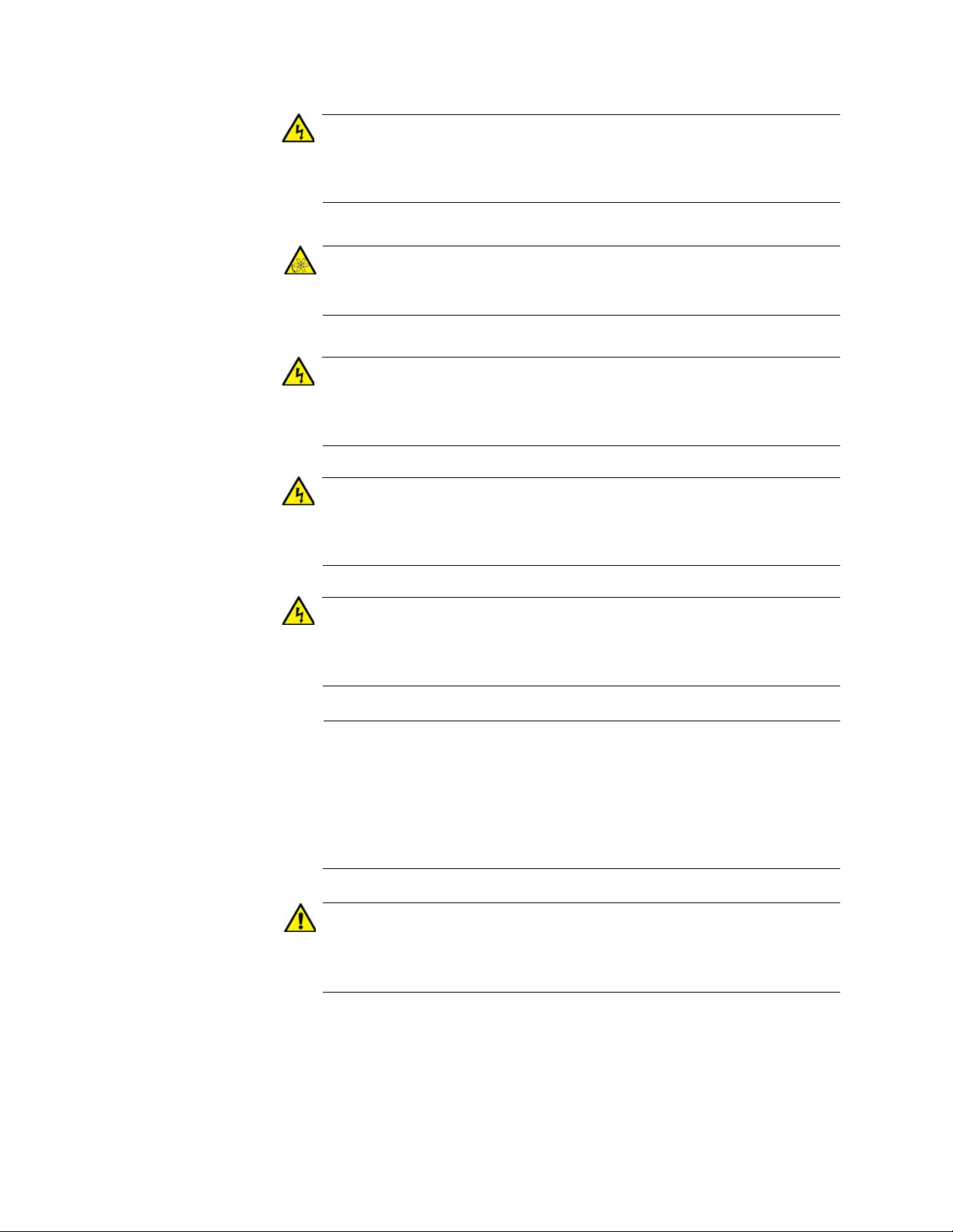
Chapter 2: Safety Precautions and Site Requirements
Warning
Warning
Warning
Warning
Warning
Note
Caution
Mounting of the equipment in the rack should be such that a
hazardous condition is not created due to uneven mechanical
loading. E25
The AT-SBxFAN06 Fan Module has hazardous moving parts. Keep
fingers away from moving fan blades.
Remove all metal jewelry, such as rings and watches, before
installing or removing a line card from a powered-on chassis.
E26
The chassis may be heavy and awkward to lift. Allied Telesis
recommends that you get assistance when mounting the chassis in
an equipment rack. E28
This unit might have more than one power cord. To reduce the risk
of electric shock, disconnect all power cords before servicing the
unit. E30
If installed in a closed or multi-unit rack assembly, the operating
ambient temperature of the rack environment may be greater than
the room ambient temperature. Therefore, consideration should be
given to installing the equipment in an environment compatible with
the manufacturer’s maximum rated ambient temperature (Tmra).
E35
Installation of the equipment in a rack should be such that the
amount of air flow required for safe operation of the equipment is not
compromised. E36
66
Page 67
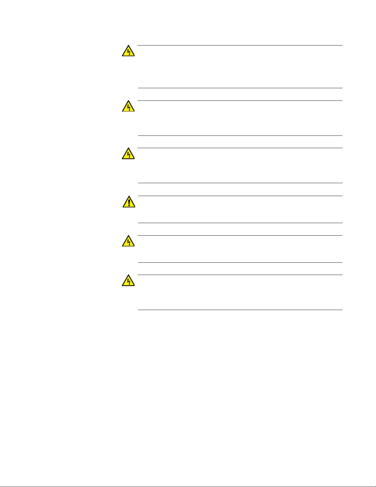
SwitchBlade x8106 Chassis Switch Installation Guide
Warning
Warning
Warning
Caution
Warning
Warning
Reliable earthing of rack-mounted equipment should be maintained.
Particular attention should be given to supply connections other than
direct connections to the branch circuits (e.g., use of power strips).
E37
To reduce the risk of electric shock, the PoE ports on this product
must not connect to cabling that is routed outside the building where
this device is located. E40
This product may have multiple AC power cords installed. To deenergize this equipment, disconnect all power cords from the device.
E43
An Energy Hazard exists inside this equipment. Do not insert hands
or tools into open chassis slots or sockets. E44
This equipment shall be installed in a Restricted Access location.
E45
High Leakage Current exists in this chassis. Connect external
ground wire before connecting AC power supply(s).
E46
67
Page 68

Chapter 2: Safety Precautions and Site Requirements
Selecting a Site for the SwitchBlade x8106
Please perform the following procedure to determine the suitability of the
site for the chassis:
1. Verify that the equipment rack is safely secured so that it will not tip
over. You should install devices starting at the bottom of the rack, with
the heavier devices near the bottom.
2. Verify that the power outlets for the chassis are located near the unit
and are easily accessible.
3. Verify that the power sources are on different A/C circuits to protect
the unit from a power circuit failure.
4. Verify that the site has dedicated power circuits or power conditioners
to supply reliable electrical power to the network devices.
5. Verify that the site allows for easy access to the ports on the front of
the chassis so that you can easily connect and disconnect the network
cables, as well as view the unit’s LEDs.
6. Verify that the site allows for adequate air flow around the unit and
through the cooling vents. The ventilation direction for the main section
of the chassis is from left to right (when facing the front of the chassis),
with the fan module drawing air out of the chassis. The power supplies
have fans that draw air from the front to the back.
7. Verify that the site has a reliable and earth (grounded) power supply
source, preferably dedicated and filtered.
8. Verify that the twisted pair cabling is not exposed to sources of
electrical noise, such as radio transmitters, broadband amplifiers,
power lines, electric motors, and fluorescent fixtures.
9. Verify that the site protects the chassis from moisture, water, and dust.
Here are other guidelines to consider:
Switch ports are suitable for intra-building connections, or where
non-exposed cabling is required.
Do not place objects on top of the chassis.
The power cords provided with the AT-SBxPWRSYS1 and AT-
SBxPWRPOE1 AC Power Supplies for 100-125 VAC installations
have 20 Amp, 125 V NEMA 5-20P plugs. The plugs are only
compatible with NEMA 5-20R receptacles. See Figure 28 on page
69.
68
Page 69

SwitchBlade x8106 Chassis Switch Installation Guide
Figure 28. 100 - 125 VAC 125 V NEMA 5-20 Plug and Receptacle
69
Page 70

Chapter 2: Safety Precautions and Site Requirements
Installation Tools and Material
This section lists the tools and material you need to supply to install the
product:
Here are the items for installing the chassis in an equipment rack:
#2 Phillips-head screwdriver
Six equipment rack screws
Flat-head screwdriver
#2 Phillips-head 10 inch-lbs torque screwdriver (optional)
Here are the items for installing the grounding wire:
#2 Phillips-head screwdriver
Crimping tool
10 AWG stranded grounding wire
#2 Phillips-head 20 inch-lbs torque screwdriver (optional)
Here are the items for installing the AT-SBxPWRSYS1 DC Power Supply:
Two 8 AWG power wires
One 10 AWG stranded grounding wire
8 mm wrench
#1 Phillips-head screwdriver
#3 Phillips-head screwdriver
#3 Phillips-head 30 to 40 inch-lbs torque screwdriver (optional)
Here are the items for installing the AT-SBx81CFC400 Controller Fabric
Card and Ethernet line cards:
#2 Phillips-head screwdriver
#2 Phillips-head, 5 inch-lbs torque screwdriver (optional)
70
Page 71

Chapter 3
Installing the Chassis in an Equipment Rack
This chapter describes how to install the AT-SBx8106 Chassis in an
equipment rack. This chapter contains the following sections:
“Required Tools and Material” on page 72
“Preparing the Equipment Rack” on page 73
“Unpacking the AT-SBx8106 Chassis” on page 76
“Removing the Rubber Feet” on page 78
“Adjusting the Equipment Rack Brackets” on page 80
“Installing the Chassis in the Equipment Rack” on page 82
“Removing the Shipping Brace” on page 86
“Installing the Chassis Grounding Lug” on page 87
71
Page 72

Chapter 3: Installing the Chassis in an Equipment Rack
Warning
Required Tools and Material
You need the following tools and material to install the product in an
equipment rack:
#2 Phillips-head screwdriver
Six equipment rack screws
Flat-head screwdriver
#2 Phillips-head 10 inch-lbs torque screwdriver (optional)
The chassis may be heavy and awkward to lift. Allied Telesis
recommends that you get assistance when mounting the chassis in
an equipment rack. E30
72
Page 73

Preparing the Equipment Rack
Caution
To prepare the equipment rack for the AT-SBx8106 Chassis, perform the
following procedure:
The chassis is heavy and should be mounted as low as possible in
the equipment rack to maximize vertical stability.
1. Reserve 190.0 mm (7.5“) of vertical rack space for the installation of
the AT-SBx8106 Chassis, as shown in Figure 29 on page 74.
2. Do not mount any equipment within 152.4 mm (6”) above this space
during installation. This additional vertical space is temporary and
allows you enough room to lift and tilt the chassis into its position in the
equipment rack without striking other equipment. You may use this
additional space for other network equipment after the chassis is
installed.
SwitchBlade x8106 Chassis Switch Installation Guide
73
Page 74

Chapter 3: Installing the Chassis in an Equipment Rack
190.0 mm (7.5“)
152.4 mm (6”0)
342.4 mm (13.5”)
74
Figure 29. Reserving Vertical Rack Space
Page 75

SwitchBlade x8106 Chassis Switch Installation Guide
6.4 mm (.25 in)
Screw head
Top screw hole of the lowest 1/2” hole pattern
away from rack
3. Identify the lowest 1/2” screw hole pattern on the rack mounting rails
within the space reserved for the AT-SBx8106 Chassis.
4. Install one rack mount screw in each vertical rail, at the same height in
the top screw hole of the lowest 1/2” hole pattern, as shown in
Figure 30. Do not fully tighten the screws at this time. The screw heads
should protrude from the rack approximately 6.4 mm (.25 in). The
screws are used to support the chassis while you secure it to the rack.
5. After installing the two screws in the equipment rack, go to “Unpacking
the AT-SBx8106 Chassis” on page 76.
Figure 30. Rack Mounting Hole Locations
75
Page 76
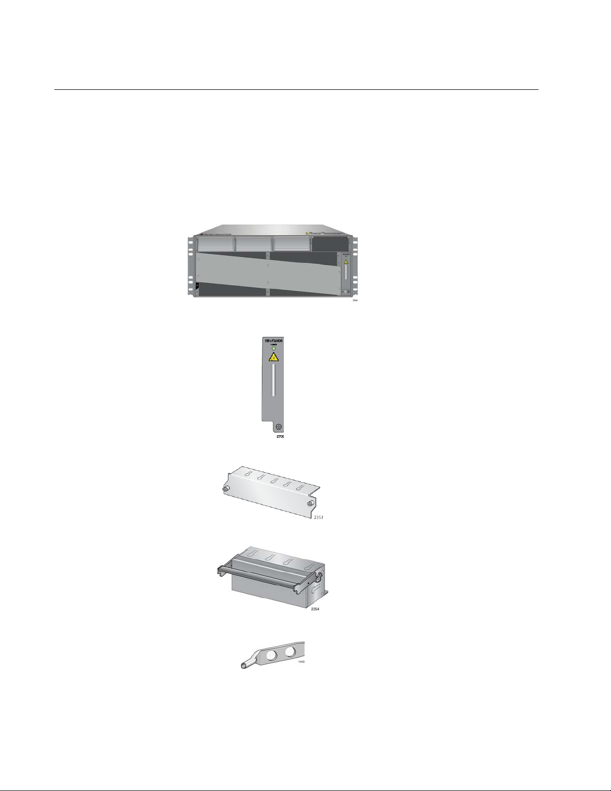
Chapter 3: Installing the Chassis in an Equipment Rack
One AT-SBx8106 Chassis
One AT-SBxFAN06 Module preinstalled in the vertical slot on
the right side of the front panel
Four blank line card slot covers
Three blank power supply slot
covers pre-installed in power
supply slots A to C on the front
panel
One grounding lug pre-installed
in the lower left corner on the
back panel
Unpacking the AT-SBx8106 Chassis
To unpack the AT-SBx8106 Chassis, perform the following procedure:
1. Remove all components from the shipping package.
2. Verify the contents of the shipping container by referring to Figure 31
here and Figure 32 on page 77. If any item is missing or damaged,
contact your Allied Telesis sales representative for assistance.
76
Figure 31. Components of the AT-SBx8106 Chassis
Page 77

SwitchBlade x8106 Chassis Switch Installation Guide
Two equipment rack brackets
pre-installed on the sides of the
chassis.
One shipping brace pre-installed
diagonally across the line card
slots on the front panel
One wrist strap
Figure 32. Components of the AT-SBx8106 Chassis (Continued)
77
Page 78

Chapter 3: Installing the Chassis in an Equipment Rack
Warning
Note
Removing the Rubber Feet
The chassis comes with rubber feet on the base panel for tabletop
installation, which is not recommended for this product. Allied Telesis
recommends removing the feet before installing the chassis in the
equipment rack. To remove the rubber feet, perform the following
procedure:
The chassis may be heavy and awkward to lift. Allied Telesis
recommends that you get assistance when lifting the chassis.
Do not remove the shipping brace from the front of the chassis until
after the unit is installed in the equipment rack. You might bend the
chassis and cause misalignment of the slots and card guides if you
lift the chassis without the shipping brace.
1. Place the unit upside down on a level, secure surface, as shown in
Figure 33.
Figure 33. Turning the Chassis Upside Down
2. Using a flat-head screwdriver, pry the rubber feet from the bottom of
the chassis, as shown in Figure 34 on page 79.
78
Page 79

SwitchBlade x8106 Chassis Switch Installation Guide
Figure 34. Removing the Rubber Feet
3. Turn the chassis over.
Go to the next procedure, “Adjusting the Equipment Rack Brackets” on
page 80.
79
Page 80

Chapter 3: Installing the Chassis in an Equipment Rack
Adjusting the Equipment Rack Brackets
The chassis has two pre-installed equipment rack brackets. You may
adjust the brackets so that the front of the chassis is flush with, extends
beyond, or is recessed behind the front of the equipment rack. You may
also install the brackets so that the rear panel of the chassis is flush with
the front of the equipment rack.
You adjust the brackets by removing them and re-installing them in
different positions on the sides of the chassis. The bracket positions are
listed in Table 20 and illustrated in Figure 35 on page 81 and Figure 36 on
page 81. Please review the following information before moving the
brackets:
Position A, the default position, positions the chassis so that the
front of the unit is flush with the front of the equipment rack.
Position B recesses the front of the chassis by 27.39 mm (1.1 in).
Positions C to E extend the front of the chassis beyond the front of
the rack from 27.39 mm (1.1 in) to 140.85 mm (5.545 in).
Position F installs the chassis with the rear panel flush with the
front of the equipment rack.
To install the rack mount brackets in position “E,” you have to
remove the two chassis screws from the bottom-middle section of
the chassis and re-install them in front where the rack mount
bracket screws were originally, as shown in Figure 35 on page 81.
The dimension (X) between the front panel and the rack rails is
given for each rack mounting bracket position in Table 20.
Table 20. Front Panel to Rack Rail Dimensions
Figure # Front Panel Position
35 A
3.69 mm (0.145 in)
Dimension X
Front Panel to Rack Rail
(Factory Installed - Flush)
35 B
-27.39 mm (-1.078 in)
(Recessed)
35 C 27.39 mm (1.078 in)
35 D 47.71 mm (1.878 in)
80
35 E 140.85 mm (5.545 in)
36 F
374.16 mm (14.731 in)
(Reverse Position)
Page 81

SwitchBlade x8106 Chassis Switch Installation Guide
Factory Installed - Flush with Rack Rails
A
B
C D E
“Dim X”
“Dim X” “Dim X” “Dim X”
F
Front panel
facing towards
the rear of the
equipment rack.
Figure 35. Rack Mounting Bracket Locations
Figure 36. Rack Bracket Locations for Reverse Position of Chassis
81
Page 82

Chapter 3: Installing the Chassis in an Equipment Rack
Caution
Warning
Warning
Installing the Chassis in the Equipment Rack
The procedure in this section explains how to install the chassis in the
equipment rack. The procedure requires the following items:
#2 Phillips-head screwdriver (not provided)
Six equipment rack screws (not provided)
#2 Phillips-head, 10 inch-lbs torque screwdriver (optional — not
provided)
Do not remove the shipping brace from the front of the AT-SBx8106
Chassis until after the unit is securely mounted in the rack. The plate
prevents twisting of the chassis frame and mechanical misalignment
of the line card slots during shipping and installation.
The chassis may be heavy and awkward to lift. Allied Telesis
recommends that you get assistance when mounting the chassis in
an equipment rack. E30
To prevent injuring yourself or damaging the device, do not attempt
to install the chassis in the equipment rack alone. Allied Telesis
recommends a minimum of three people for this procedure.
Before installing the chassis in the rack, review the following checklist:
Did you reserve sufficient space in the equipment rack for the
chassis and install two screws in the rack on which to rest the
chassis while securing it to the rack? If not, then perform
“Preparing the Equipment Rack” on page 73.
Did you adjust the brackets so that the front of the chassis will be
positioned correctly in the equipment rack for your installation? If
not, then perform “Adjusting the Equipment Rack Brackets” on
page 80.
82
To install the AT-SBx8106 Chassis in the equipment rack, perform the
following procedure:
1. While facing the front of the chassis, tilt the top of the chassis toward
you.
Page 83

SwitchBlade x8106 Chassis Switch Installation Guide
2. Lift the AT-SBx8106 Chassis into the equipment rack and set the
bottom of the equipment rack brackets firmly on the two equipment
rack screws you installed in “Preparing the Equipment Rack” on
page 73, as shown in Figure 37.
Figure 37. Lifting the AT-SBx8106 Chassis into the Equipment Rack
3. With the bottom of the rack mount ears resting on the two rack mount
screws, tilt the top of the chassis back until both rackmount brackets
are flush and parallel with the vertical rack rails.
4. Install four rack mount screws (not provided) to secure the chassis to
the equipment rack, as shown in Figure 38 on page 84.
83
Page 84

Chapter 3: Installing the Chassis in an Equipment Rack
Screws
Screws
Figure 38. Installing the Rack Mount Screws
5. Tighten all six screws shown in Figure 39 on page 85 to secure the
chassis to the equipment rack, Allied Telesis recommends tightening
the screws to 10 inch-lbs.
84
Page 85
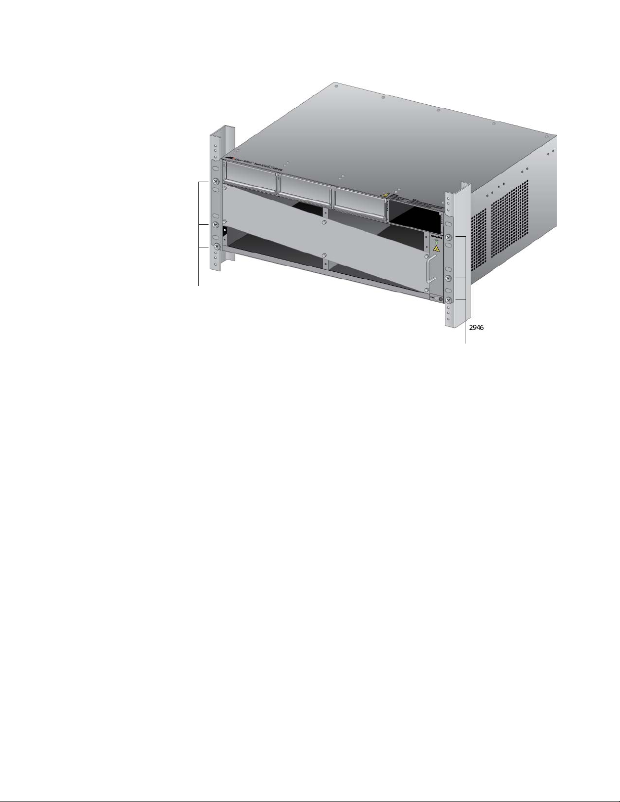
SwitchBlade x8106 Chassis Switch Installation Guide
Screws
Screws
Figure 39. Tightening the Rack Mount Screws
6. Go to “Removing the Shipping Brace” on page 86.
85
Page 86

Chapter 3: Installing the Chassis in an Equipment Rack
Shipping Brace Screws
Removing the Shipping Brace
Now that the chassis is installed in the equipment rack, you may remove
the shipping brace from the front of the unit. To remove the shipping
brace, remove the six mounting screws with a #2 Phillips-head
screwdriver (not provided). Refer to Figure 40.
86
Figure 40. Removing the Shipping Brace
After removing the shipping plate, go to “Installing the Chassis Grounding
Lug” on page 87.
Page 87

Installing the Chassis Grounding Lug
This procedure explains how to connect a grounding wire to the chassis.
The chassis requires a permanent connection for the line cards and power
supplies to a good earth ground. The procedure requires the following
items:
Grounding lug (pre-installed on the rear panel of the chassis)
#2 Phillips-head screwdriver (not provided)
Crimping tool (not provided)
10 AWG stranded grounding wire (not provided)
#2 Phillips-head, 20 inch-lbs torque screwdriver (optional — not
provided)
To connect the chassis to an earth ground, perform the following
procedure:
SwitchBlade x8106 Chassis Switch Installation Guide
1. Prepare an adequate length of stranded grounding wire (10 AWG) for
the ground connection by stripping it as shown in Figure 41.
Figure 41. Stripping the Grounding Wire
2. Remove the two screws that secure the grounding lug to the rear panel
of the chassis, as shown in Figure 42.
Figure 42. Removing the Grounding Lug
87
Page 88

Chapter 3: Installing the Chassis in an Equipment Rack
3. Insert one end of the grounding wire into the grounding lug, as shown
in Figure 43, and use a crimping tool to secure the wire to the
grounding lug.
Figure 43. Attaching the Grounding Wire to the Grounding Lug
4. Install the grounding lug on the rear panel of the chassis, as shown in
Figure 44. Allied Telesis recommends tightening the screws to
20 inch-lbs.
88
Figure 44. Installing the Grounding Lug and Wire
5. Connect the other end of the grounding wire to the building protective
earth.
6. Go to Chapter 4, “Installing the Power Supplies” on page 89.
Page 89

Chapter 4
Installing the Power Supplies
This chapter explains how to install the power supplies. It has the following
sections:
“Protecting Against Electrostatic Discharge (ESD)” on page 90
“Installing the AT-SBxPWRSYS1 AC System Power Supply” on
page 91
“Installing the AT-SBxPWRPOE1 PoE Power Supply” on page 97
“Installing the AT-SBxPWRSYS1 DC Power Supply” on page 103
89
Page 90

Chapter 4: Installing the Power Supplies
Caution
Protecting Against Electrostatic Discharge (ESD)
To protect the equipment from damage by Electrostatic Discharge (ESD)
during the installation procedure, observe proper ESD protection when
handling the SwitchBlade x8106 line cards and power supplies. You
should be properly grounded with a wrist or foot strap.
Electrostatic Discharge (ESD) can damage the components on the
SwitchBlade x8106 line cards and power supplies. Be sure to follow
proper ESD procedures during the installation.
To guard against ESD, perform this procedure:
1. Verify that the chassis is electrically connected to earth ground.
2. Connect the wrist strap that comes with the chassis to the ESD socket
in the bottom right corner of the AT-SBx8106 Chassis, shown in
Figure 45. This ensures that ESD voltages safely flow to ground.
90
Figure 45. ESD Socket and Wrist Strap
3. When you put on the ESD-preventive wrist strap, be sure it makes
good contact with your skin.
Page 91

SwitchBlade x8106 Chassis Switch Installation Guide
Warning
Caution
Slot A
AT-SBxPWRPOE1
Power Supply
Slot B
AT-SBxPWRPOE1
Power Supply
Slot C
AT-SBxPWRSYS1
Power Supply
Slot D
AT-SBxPWRSYS1
Power Supply
Installing the AT-SBxPWRSYS1 AC System Power Supply
For background information on the AT-SBxPWRSYS1 Power Supply, refer
to “AT-SBxPWRSYS1 AC Power Supply” on page 53. The chassis must
have at least one AT-SBxPWRSYS1 Power Supply.
The electronic components in the AT-SBxPWRSYS1 Power Supply
can be damaged by electro-static discharges (ESD). Follow the
procedure in “Protecting Against Electrostatic Discharge (ESD)” on
page 90 to guard against ESD damage when unpacking and
installing the power supply.
To install the AT-SBxPWRSYS1 Power Supply, perform the following
procedure:
1. Choose a slot for the AT-SBxPWRSYS1 Power Supply in the chassis.
You may install it in either slot C and D, shown in Figure 46. The first
AT-SBxPWRSYS1 Power Supply should be installed in slot D,
because the slot does not have a blank power supply panel.
The AT-SBxPWRSYS1 Power Supply will not work in slot A or B.
Figure 46. Power Supply Slots
2. If the chassis already has a power supply in slot D, remove the blank
power supply panel from slot C by lifting the blank panel handle and
sliding it out of the slot, as shown in Figure 47 on page 92.
91
Page 92
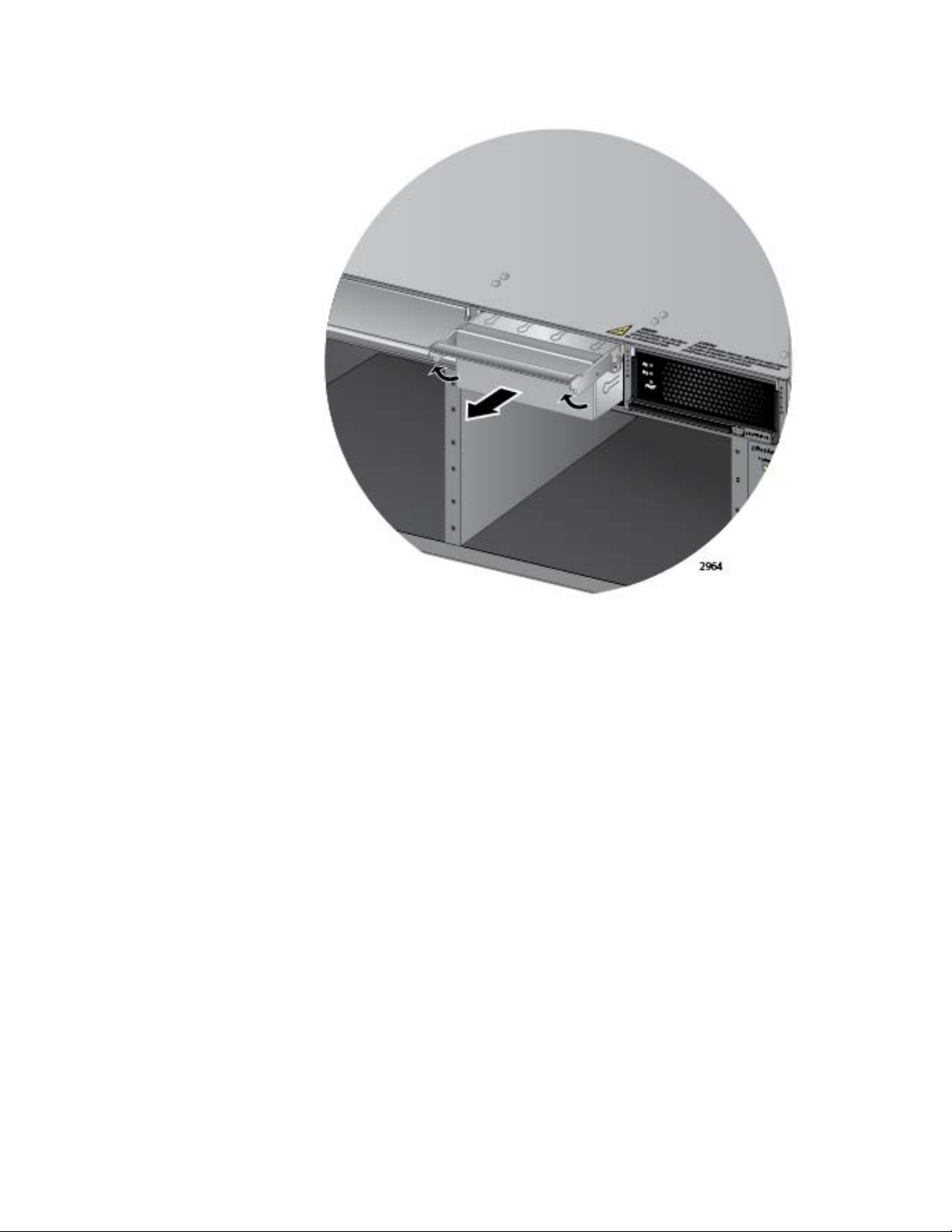
Chapter 4: Installing the Power Supplies
Figure 47. Removing the Blank Slot Cover from Power Supply Slot C
3. Remove the new AT-SBxPWRSYS1 Power Supply from the shipping
package and verify the package contents, listed in Figure 48 on page
93.
If any item is missing or damaged, contact your Allied Telesis sales
representative for assistance.
92
Page 93

SwitchBlade x8106 Chassis Switch Installation Guide
Note
Note
One AT-SBxPWRSYS1
Power Supply Module
One regional AC power cord
One tie wrap
Figure 48. Items Included with the AT-SBxPWRSYS1 Power Supply
Module
Store the packaging material in a safe location. You must use the
original shipping material if you need to return the unit to Allied
Telesis.
The tie wrap is used to secure the power cord to the chassis, as
explained in “Powering On the AT-SBxPWRSYS1 AC Power
Supply” on page 145.
93
Page 94

Chapter 4: Installing the Power Supplies
4. Check the power supply for its model name, shown in Figure 49, to
verify the module.
If the module is the AT-SBxPWRPOE1 PoE Power Supply, do not
continue with this procedure. Instead, perform “Installing the ATSBxPWRPOE1 PoE Power Supply” on page 97.
Figure 49. Verifying the AT-SBxPWRSYS1 Power Supply
5. Move the locking handle on the AT-SBxPWRSYS1 Power Supply to
the unlocked or up position. See Figure 50.
Figure 50. Unlocking the Handle on the AT-SBxPWRSYS1 Power Supply
94
Page 95

SwitchBlade x8106 Chassis Switch Installation Guide
6. Align and insert the AT-SBxPWRSYS1 Power Supply into the power
supply slot. Figure 51 shows the power supply installed in slot D.
Figure 51. Inserting the AT-SBxPWRSYS1 Power Supply
95
Page 96

Chapter 4: Installing the Power Supplies
Note
7. Lower the power supply locking handle to secure the power supply to
the chassis, as shown in Figure 52.
Figure 52. Lowering the Handle on the AT-SBxPWRSYS1 Power Supply
8. To install a second AT-SBxPWRSYS1 Power Supply, repeat this
procedure.
After installing the AT-SBxPWRSYS1 Power Supples, do one of the
following:
If you purchased the AT-SBxPWRPOE1 Power Supply for the ports on
the AT-SBx81GP24 PoE Line Cards, go to “Installing the ATSBxPWRPOE1 PoE Power Supply” on page 97.
Otherwise, go to Chapter 5, “Installing the AT-SBx81CFC400
Controller and Ethernet Line Cards” on page 109.
Retain the tie wrap that comes with the power supply. You will use it
to secure the power cord to the chassis when you power on the unit
in “Powering On the AT-SBxPWRSYS1 AC Power Supply” on
page 145.
96
Page 97
SwitchBlade x8106 Chassis Switch Installation Guide
Caution
Installing the AT-SBxPWRPOE1 PoE Power Supply
This section contains the installation procedure for the AT-SBxPWRPOE1
Power Supply, for the PoE+ ports on the AT-SBx81GP24 PoE Line Card.
For background information, refer to “AT-SBxPWRPOE1 Power Supply”
on page 55.
The electronic components in the AT-SBxPWRPOE1 PoE Power
Supply can be damaged by electro-static discharges (ESD). Follow
the procedure in “Protecting Against Electrostatic Discharge (ESD)”
on page 90 to guard against ESD damage when unpacking and
installing the power supply.
To install the power supply, perform the following procedure:
1. Choose a slot for the AT-AT-SBxPWRPOE1 System Power Supply in
the chassis.
You may install it in either slot A or B, shown in Figure 46 on page 91.
2. Raise the handle on the blank panel covering the selected slot and
slide the panel from the chassis. Figure 53 on page 98 shows the
blank panel being removed from slot A.
97
Page 98
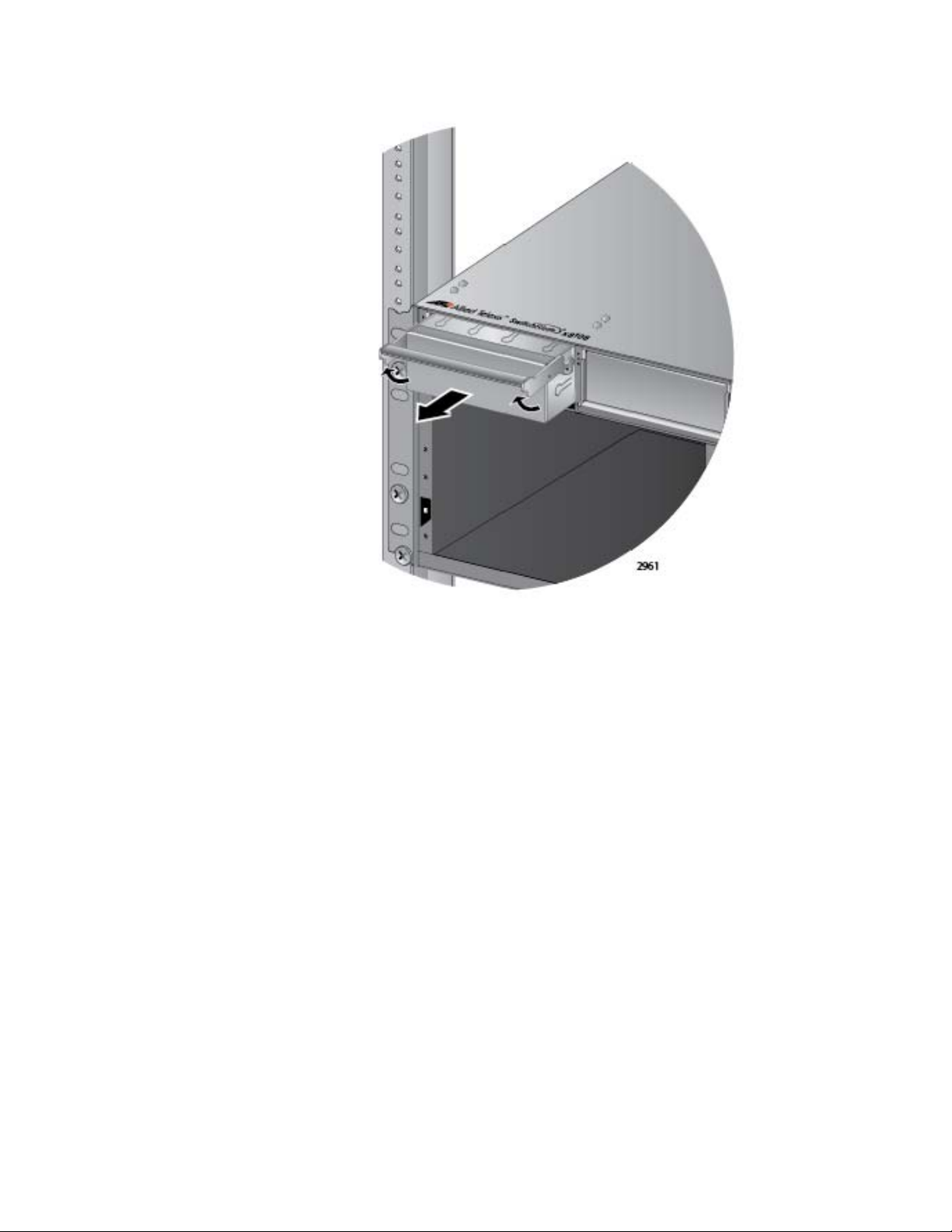
Chapter 4: Installing the Power Supplies
Figure 53. Removing the Blank Slot Cover from Power Supply Slot A
3. Remove the power supply from the shipping package and verify that
the shipping package contains the items listed in Figure 54 on page
99.
If any item is missing or damaged, contact your Allied Telesis sales
representative for assistance.
98
Page 99

SwitchBlade x8106 Chassis Switch Installation Guide
Note
Note
One AT-SBxPWRPOE1
Power Supply Module
One regional AC power cord
One tie wrap
Figure 54. Items Included with the AT-SBxPWRPOE1 Power Supply
Module
Store the packaging material in a safe location. You must use the
original shipping material if you need to return the unit to Allied
Telesis.
The tie wrap is used to secure the power cord to the chassis in
“Powering On the AT-SBxPWRPOE1 Power Supply” on page 148.
99
Page 100

Chapter 4: Installing the Power Supplies
Caution
4. Check the model name, shown in Figure 55, to verify the module.
If the module is the AT-SBxPWRSYS1 System Power Supply, do not
continue with this procedure. Instead, perform “Installing the ATSBxPWRSYS1 AC System Power Supply” on page 91.
Figure 55. Verifying the AT-SBxPWRPOE1 PoE Power Supply
5. Raise the locking handle on the AT-SBxPWRPOE1 Power Supply, as
shown Figure 56.
100
Figure 56. Unlocking the Handle on the AT-SBxPWRPOE1 Power Supply
6. Align and insert the AT-SBxPWRPOE1 Module into slot A or B. Figure
57 on page 101 shows the power supply module aligned in slot A.
The AT-SBxPWRPOE1 AC Power Supply will not work in slot C or
D.
 Loading...